1
Model No. 831.23880.0
Serial No.
Write the serial number in the space
above for reference.
Serial Number
Decal (under frame)
• Assembly
• Operation
• Maintenance
• Part List and Drawing
Sears, Roebuck and Co.
Hoffman Estates, IL 60179
HYBRID TRAINER
User's Manual
TABLE OF CONTENTS
WARNING DECAL PLACEMENT ...............................................................
IMPORTANT PRECAUTIONS ..................................................................
BEFORE YOU BEGIN ........................................................................
PART IDENTIFICATION CHART ................................................................
ASSEMBLY ................................................................................
HOW TO USE THE HYBRID TRAINER .........................................................
FCC INFORMATION ........................................................................
MAINTENANCE AND TROUBLESHOOTING
....................................................
EXERCISE GUIDELINES ....................................................................
PART LIST ................................................................................
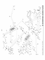
EXPLODED DRAWING ......................................................................
ORDERING REPLACEMENT PARTS ...................................................
90 DAY FULL WARRANTY ...........................................................
2
3
4
5
6
15
20
21
23
25
26
Back Cover
Back Cover
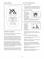
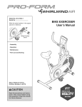
WARNING DECAL PLACEMENT
This drawing shows the location(s) of the warning decal(s).
if a decal is missing or illegible, call 1-888-533-1333 and
request a free replacement decal. Apply the decal in the
location shown. Note: The decal(s) may not be shown at
actual size.
Misuse
of this machine
may result
injury.
,Read
in serious
user's
manual
prior to use and follow
all warnings
end
instructions.
,Do not allow
on or around
, Pedals
--
children
machine.
continue
spin when
pedaling.
to
you stop
,Spinning
pedals
cause injury.
can
,Reduce
pedal speed
a controlled
manner.
,User weight must
exceed 350 Ihs /
not
159 kgs.
.This
product
should
always
he used on a
level surface.
.This product
is not
intended
for
therapeutic
Replace
damaged,
use.
mabel if
illegib|e,
or removed._
2
in
iMPORTANT PRECAUTIONS
WARNING: Toreduce
theriskofser oos
njury,
read
a, important
precaot ons
and
instructions in this manual and all warnings on your hybrid trainer before using your hybrid trainer.
Sears assumes no responsibility
for personal injury or property damage sustained by or through the
use of this product.
.
it is the responsibility
of the owner to ensure
that all users of the hybrid trainer are adequately informed of all precautions.
.
Before beginning any exercise program,
consult your physician. This is especially
important for persons over age 35 or persons with pre-existing health problems.
.
Use the hybrid trainer only as described
this manual.
.
The hybrid trainer is intended for home use
only. Do not use the hybrid trainer in a commercial, rental, or institutiona! setting.
,
persons weighing more than 350 Ibs.
(159 kg).
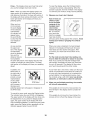
10. Wear appropriate clothes while exercis=
ing; do not wear loose clothes that could
become caught on the hybrid trainer. Always
wear athletic shoes for foot protection while
exercising.
11. Hold the handlebars or the upper body arms
when mounting, dismounting,
or using the
hybrid trainer.
in
12. Make sure that the pedal knobs are fully
tightened each time you use the hybrid
trainer.
Keep the hybrid trainer indoors, away from
moisture and dust. Do not put the hybrid
trainer in a garage or covered patio or near
13. The heart rate monitor
water.
=
7.
.
9.
is not a medical
device. Various factors may affect the accuracy of heart rate readings. The heart rate
monitor is intended only as an exercise aid
in determining heart rate trends in general.
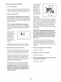
Place the hybrid trainer on a level surface,
with at least 3 ft. (0.9 m) of clearance in the
front and rear of the hybrid trainer and 2 ft.
(0.6 m) on each side. To protect the floor or
carpet from damage, place a mat under the
hybrid trainer.
14. The hybrid trainer does not have a freewheel;
the pedals will continue to move until the
flywheel stops. Reduce your pedaling speed
in a controlled way.
inspect and properly tighten all parts regularly. Replace any worn parts immediately.
15. Keep your back straight while using the
hybrid trainer; do not arch your back.
Keep children under age 12 and pets away
from the hybrid trainer at all times.
16. Over exercising may result in serious injury
or death, if you feel faint or if you experience
pain while exercising, stop immediately and
cool down.
The hybrid trainer should
not be used by
3
BEFORE YOU BEGIN
Thank you for selecting the revolutionary PROFORM <R_
HYBRID TRAINER. The HYBRID TRAINER provides
an impressive selection of features designed to make
your workouts at home more effective and enjoyable.
manual. To help us assist you, note the product model
number and serial number before contacting us. The
model number and the location of the serial number
decal are shown on the front cover of this manual.
For your benefit, read this manual carefully before
you use the hybrid trainer. If you have questions after
reading this manual, please see the back cover of this
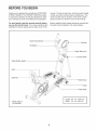
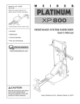
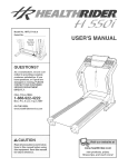
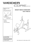
Before reading further, please familiarize yourself with
the parts that are labeled in the drawing below.
Heart Rate Monitor
Console
Handlebar
Upper Body Arm
Console Knob
Water Bottle Holder*
Seat
Backrest
Pedal Brace
Pedal
Pedal Knob
Length: 6 ft. 4 in. (193 cm)
Width: 2 ft. 2 in. (66 cm)
*Water bottle is
not included
4
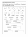
PART iDENTiFiCATiON
CHART
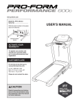
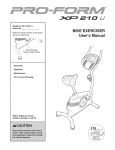
Use the drawings below to identify the small parts needed for assembly. The number in parentheses below each
drawing is the key number of the part, from the PART LIST near the end of this manual. The number following the
key number is the quantity needed for assembly. Note: If a part is not in the hardware kit, check to see if it
has been preassembled. Extra parts may be included.
M6 Locknut
(51 )-4
M8 Locknut
(10)-10
M8 Small
Washer
(93)-4
M8 Split
Washer
(42)-8
M4 x 16mm
Screw (47)-8
MIO Locknut
(48)-1
M8 Large
Washer (54)-4
M6 x 30mm
Bolt (49)-4
Wave Washer
(81)-4
M10 Split
Washer (98)-2
M8 x 13mm
Screw (95)-6
M8 x 40mm Bolt (83)-6
M6 Curved
Washer
(25)-4
M10 Curved
Washer (39)-3
M8 x 20mm
Screw (34)-4
M8 x 65mm Bolt (94)-2
M8 x 125mm Bolt (58)-2
MIO x 25mm
Screw (96)-1
M10 x 54mm Screw (97)-1
M10 x 65mm Screw (40)-4
MIO x 60mm Bolt (61)-1
5
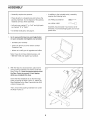
ASSEMBLY
Assembly requires two persons.
in addition to the included tool(s), assembly
requires the following tools:
Place all parts in a cleared area and remove the
packing materials. Do not dispose of the packing
materials until you finish assembly.
one Phillips screwdriver
one rubber mallet
Left parts are marked "L" or "Left" and right parts
are marked "R" or "Right."
Go to www.proformservice.com/registration
on your computer and register your product.
• activates your warranty
• saves you time if you ever need to contact
Customer Care
• allows us to notify you of upgrades and offers
Note: if you do not have Internet access, call
1-888-533-1333 and register your product.
.
(_
Assembly may be easier if you have a set of
wrenches. To avoid damaging parts, do not use
power tools.
To identify small parts, see page 5.
.
_
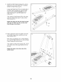
With the help of a second person, place some
of the packing materials (not shown) under the
Rear Frame (1). Have the second person hold
the Rear Frame to prevent it from tipping
while you complete this step.
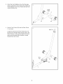
Orient the Rear Stabilizer (6) so that the large
holes are facing the Rear Frame (1). Attach the
Rear Stabilizer to the Rear Frame with two M10
x 65mm Screws (40).
Then, remove the packing materials from under
the Rear Frame (1).
Large
Holes
40
6
Orient the Front Stabilizer (2) so that the large
holes are facing the Front Frame (23). Attach the
Front Stabilizer to the Front Frame with two M10
x 65mm Screws (40).
Large
Holes
23
.
Set the Front Frame (23) near the Rear Frame
(1) as shown.
40
Wire Tie
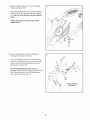
Locate the wire tie in the Front Frame (23). Tie
the wire tie to the Main Wire Harness (45) in the
Rear Frame (1). Then, pull the upper end of the
wire tie until the Main Wire Harness is routed
through the Front Frame.
Wire
Tie_
7
23
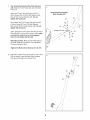
.
Tip: Avoid pinching the Main Wire Harness
(45). Slide the Front Frame (23) onto the Rear
Frame (1).
5
Avoid pinching the Main
Wire Harness (45)
Attach the Front Frame (23) with an M10 x
25mm Screw (96), an M10 Split Washer (98),
and an M10 Curved Washer (39). Do not
tighten the Screw yet.
23
Next, attach the Front Frame (23) with an M10
x 54mm Screw (97), an M10 Split Washer
(98), and an M10 Curved Washer (39). Do not
tighten the Screw yet.
61
Hexagonal
Then, attach the Front Frame (23) with an M10 x
60mm Bolt (61) and an M10 Locknut (48); make
sure that the Locknut is in the hexagonal
hole. Do not tighten the Bolt yet.
45
See steps 2 and 3. Make sure that the ends of
the Rear Stabilizer (6) and the Front Stabilizer
(2) are touching the floor.
Tighten the Bolt and the Screws (61, 96, 97).
.
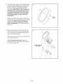
Hold the Console Post (73) near the Front Frame
(23) as shown. Insert the Main Wire Harness
(45) upward through the Console Post.
45
8
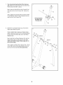
.
Tip: Avoid pinching the Main Wire Harness
(45). Slide the Console Post (73) onto the Front
Frame (23) and hold it in place.
Next, insert the Axle (80) into the Console Post
(73) and into the Front Frame (23). Center the
Axle.
Then, tighten the Console Knob (9) with an M10
Curved Washer (39) into the Console Post (73)
and into the Front Frame (23).
Avoid pinching
the Main Wire
Harness (45)
9
45
39
23
.
Identify the Left Upper Body Leg (74) and the
Right Upper Body Leg (86).
Using a plastic bag to keep your fingers clean,
apply a generous amount of the included grease
to each side of the Axle (80) and to two Wave
Washers (81).
90
54
Grease
34
Next, slide the two Wave Washers (81) and the
Upper Body Legs (74, 86) onto the Axle (80);
make sure that the Upper Body Legs are on
the correct sides.
Grease
81
74
Then, tighten an M8 x 20mm Screw (34), a Pivot
Cover (90), and an M8 Large Washer (54) into
each end of the Axle (80) at the same time.
80
81
54
34
9
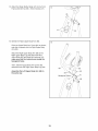
9.
Identify the Right Pedal Carriage (64), which is
attached to one of the Pedals (67). In addition,
identify the Right Pedal Leg (71).
9
79
Loosen the Pedal Knob (70) on the right side of
the Right Pedal Carriage (64), slide the Right
Pedal Carriage as far as possible onto the
Right Pedal Leg (71), and then tighten the
Pedal Knob.
65
67
\
Then, attach a Small Bumper (69) to the underside of the Right Pedal Leg (71) with an M4 x
16mm Screw (47).
71
Repeat this step with the Left Pedal Carriage
(65), the Left Pedal Leg (79), and the other
Small Bumper (not shown).
10. Apply a generous amount of grease to the axle
on the Right Upper Body Leg (86) and to two
Wave Washers (81).
10
Next, slide a Leg Bushing (13), a Wave Washer
(81), and the Right Pedal Leg (71) with the Right
Pedal Carriage (64) onto the axle.
Then, tighten an M8 x 20mm Screw (34), a Pivot
Cover (90), and an M8 Large Washer (54) into
the axle.
Repeat this step on the other side of the
hybrid trainer.
10
11. Slide the Right Pedal Leg (71) onto the Right
Pedal Leg Bracket (75).
11
Attach the Right Pedal Leg (71) with three M8 x
13mm Screws (95) and three M8 Split Washers
(42). Start all three Screws, and then tighten
them.
Repeat this step on the other side of the
hybrid trainer.
71
75
95
12. Have a second person hold the Handlebar
(53) near the Console Post (73).
12
Insert the indicated wire tie into the hole in the
side of the Console Post (73), and then pull the
wire tie until the Pulse Wires (68) are routed
through the Console Post.
45
53
Tip: Avoid pinching the wires. Attach the
Handlebar (53) to the Console Post (73) with two
M8 x 65mm Bolts (94), two M8 Split Washers
(42), and two M8 Locknuts (10).
94
42
10
Wi re
Tie
Avoid pinching
the wires
11
13. The Console (16) requires four AA batteries (not
included); alkaline batteries are recommended.
Do not use old and new batteries together or
alkaline, standard, and rechargeable batteries together, iMPORTANT: if the Console has
been exposed to cold temperatures,
allow it
to warm to room temperature before inserting batteries. Otherwise, you may damage
the console displays or other electronic
components.
13
16
X
Y
Cover
Remove the battery cover from the back of the
Console (16), and insert batteries into the battery
compartment. Make sure to orient the batteries as shown by the diagram inside the
battery compartment. Then, reattach the battery cover.
14. Have a second person hold the Console (16)
near the Console Post (73). Connect the wires
on the Console to the Main Wire Harness (45)
and to the Pulse Wires (68).
14
16
\
Insert the excess wire into the Console Post (73)
or into the Console (16).
45
Tip: Avoid pinching the wires. Attach the
Console (16) to the Console Post (73) with four
M4 x 16mm Screws (47).
Avoid pinching
the wires
12
15. Attach the Water Bottle Holder (27) to the Front
Frame (23) with two M4 x 16mm Screws (47).
15
16. Identify the Right Upper Body Arm (88).
\
16
Orient an Upper Body Arm Cover (82) as shown,
and slide it upward onto the Right Upper Body
Arm (88).
Attach the Right Upper Body Arm (88) to the
Right Upper Body Leg (86) with three M8 x
40mm Bolts (83) and three M8 Locknuts (10);
make sure that the Locknuts are inside the
hexagonal holes.
Then, slide the Upper Body Arm Cover (82)
downward onto the Right Upper Body Leg (86).
Assemble the Left Upper Body Arm (89) in
the same way.
Hexagonal
13
17. Attach a Seat Handle (59) to the Right Seat
Bracket (15) with two M6 x 30mm Bolts (49), two
M6 Curved Washers (25), and two M6 Locknuts
(51); make sure that the Locknuts are in the
hexagonal holes.
17
Attach the other Seat Handle (not shown) in
the same way.
51
15
49
18. Attach the Left and Right Seat Brackets (14, 15)
to the Rear Frame (1) with two M8 x 125mm
Bolts (58), four M8 Small Washers (93), and two
M8 Locknuts (10).
25
59
18
10
93
19. Make sure that all parts of the hybrid trainer are properly tightened. Note: Extra parts may be included.
To protect the floor or carpet from damage, place a mat under the hybrid trainer.
14
HOW TO USE THE HYBRID TRAINER
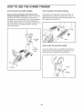
HOW TO MOVE THE HYBRID TRAINER
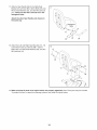
HOW TO ADJUST THE PEDAL POSiTiON
Due to the size and weight of the hybrid trainer,
moving it requires two persons. Stand in front of the
hybrid trainer, hold the console post, and place one
foot against one of the wheels. Pull on the console post
and have a second person lift the rear stabilizer until
the hybrid trainer will roll on the wheels. Carefully move
the hybrid trainer to the desired location, and then
lower it to the floor.
Each pedal can be adjusted to several positions. To
adjust each pedal, loosen the pedal knob, move the
pedal forward or backward to the desired position, and
then retighten the pedal knob.
_._
Console
Knob
HOW TO USE THE ELLiPTiCAL
_I_--_,_.,.
__J_j-.._
//
MODE
To use the hybrid trainer as an elliptical, first pivot the
console post to the high position and tighten the console knob and the washer into the front frame.
your foot
here
Knob
Lift here
15
Then, lift a pedal, fold the brace upward against the
pedal, and pivot the pedal downward to the low position. Repeat this action for the other pedal.
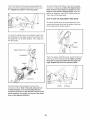
To dismount the hybrid trainer, wait until the pedals
come to a complete stop. Note: The hybrid trainer
does not have a free wheel; the pedals will continue to move until the flywheel stops. When the
pedals are stationary, step off the higher pedal first.
Then, step off the lower pedal.
HOW TO USE THE RECUMBENT
@
BIKE MODE
To use the hybrid trainer as a recumbent bike, first
remove the console knob and the washer, and pivot
the console post to the low position.
@
Brace
To mount the hybrid trainer in the elliptical mode, hold
the handlebars or the upper body arms and step onto
the pedal that is in the lower position. Then, step onto
the other pedal.
Knob
Washer
Upper Body
Then, lift a pedal, unfold the brace, and insert the end
of the brace into the pedal carriage. Make sure that
the brace is securely inserted into the pedal car=
riage. Repeat this action for the other pedal.
Pedals
Crank Arm
°°
Push the pedals until they begin to move with a
continuous motion. Note: The crank arms can turn
in either direction. It is recommended that you
move the crank arms in the direction shown by the
arrow; however, for variety, you can turn the crank
arms in the opposite direction.
16
Bra
c/e Carriage
CONSOLE DIAGRAM
HOW TO USE THE MANUAL MODE
1.
Turn on the console.
To turn on the console, press the On/Reset button
or begin pedaling. The entire display will turn on for
a moment; the console will then be ready for use.
SCAN
TIME
DIST.
; :ZS
2.
When you turn
on the console,
the manual mode
will be selected.
8_6.2 =ca1_
--"
CALS,
PULSE
ON/RESET
SPEED
_
Select the manual mode.
RPM/TARGET
[3CAN
TIME
DIST,
/ U'UU
| I'11111
t'11
_'=
If you have
selected a workout, reselect the
manual mode by
pressing any of the Smart Workouts Apps buttons
repeatedly until zeros appear in the display.
DISPLAY
L
CAIS
3.
Change the resistance
As you pedal,
change the
resistance of
the pedals by
pressing the
Resistance
increase and
decrease buttons.
u
PUIS
SP
EO
RPM/TARG
T
of the pedals as desired.
SCAN
S
CALS
PULSE
Note: After you press the buttons, it will take a
moment for the pedals to reach the selected resistance level.
FEATURES OF THE CONSOLE
The console offers a selection of features designed to
make your workouts more effective.
4.
When you use the manual mode of the console, you
can change the resistance of the pedals with the touch
of a button. As you pedal, the console will provide
continuous exercise feedback. You can even measure
your heart rate using the handgrip heart rate monitor.
Follow your progress with the display.
The console has several displays that show the following workout information:
Speed--This display shows your pedaling speed,
in revolutions per minute (rpm).
The console also offers fourteen smart workouts-seven workouts for the recumbent bike mode and
seven workouts for the elliptical mode. Each workout
automatically changes the resistance of the pedals and
prompts you to vary your pedaling pace while guiding
you through an effective workout.
Time--This display shows the elapsed time.
Note: When a workout is selected, the display
shows the time remaining in the workout instead of
the elapsed time.
Distance--This
display shows the distance you
have pedaled, in total revolutions.
Before using the console, make sure that batteries are
installed (see assembly step 13 on page 12). If there
is a sheet of plastic on the display, remove the plastic.
Calories--This
display shows the approximate
number of calories you have burned.
17
Pulse--This display shows your heart rate when
you use the handgrip heart rate monitor.
To reset the display, press the On/Reset button.
To pause the console, stop pedaling. When the
console is paused, the time will flash in the display.
To continue your workout, simply resume pedaling.
Scan--When you select this display option, the
upper section of the display will show both time
and distance information, the lower left section of
the display will show calories information, and the
lower right section of the display will show your
pedaling speed.
When you turn
on the console,
the scan display
will be selected
automatically.
An indicator will
appear below
the word SCAN
to show that the
5.
Note: If there are
sheets of plas=
tic on the metal
contacts of the
Indicator
SCAN!
rIME
handgrip heart
rate monitor,
remove the plas=
tic. To measure
DIS[,
M'MM
NN
lit P_
-n.nn
L uu _u
/
Measure your heart rate if desired.
your heart rate,
hold the handgrip
heart rate monitor,
with your palms resting against the contacts. Avoid
moving your hands or gripping the contacts
tightly.
scan display is
selected.
As you exercise,
the upper section of the display
will alternately
show the elapsed
time and the
When your pulse is detected, the heart-shaped
indicator in the display will flash each time your
heart beats and two dashes will appear. After
a moment, your heart rate will be shown in the
display.
distance that you
have pedaled;
the lower left section of the display will show the
number of calories you have burned. The lower
right section of the display will show your pedaling
speed.
For the most accurate heart rate reading, con=
tinue to hold the contacts for about 15 seconds.
In addition, the
RPM meter on
If your heart rate is not shown, make sure that your
hands are positioned as described. Be careful not
to move your hand excessively or to squeeze the
contacts tightly. For optimal performance, clean
the contacts using a soft cloth; never use alcohol,
abrasives, or chemicals to clean the contacts.
Note: If you continue to hold the handgrip heart
rate monitor, the display will show your heart rate
for up to 30 seconds. The display will then show
your heart rate along with the other modes.
the right side of
the display will
provide a visual
representation
of your pedalRPM Meter
ing speed. As
you increase or
decrease your
pedaling speed, bars will appear or disappear in
the RPM meter.
.
When you are finished exercising,
will turn off automatically.
the console
If the pedals do not move for a few seconds, the
time will flash in the display and the console will
pause.
To cancel the scan mode, press the Display button.
The indicator below the word SCAN will disappear.
The upper section of the display will then show only
the elapsed time. If you press the Display button
again, the upper section of the display will show
only the distance pedaled. To select the scan mode
again, press the Display button repeatedly until an
indicator appears below the word SCAN.
If the pedals do not move for a few minutes, the
console will turn off and the display will be reset.
18
HOW TO USE A SMART WORKOUT
1.
Turn on the console.
The target speed
settings for the
workout will be
To turn on the console, press the On/Reset button
or begin pedaling. The entire display will turn on for
a moment; the console will then be ready for use.
shown by the
target meter in
the display. The
RPM meter will
Select a smart workout.
show your actual
pedaling speed.
Target Meter
SCAN
2.
m
&?S.
RPM Meter
When you select a Recumbent smart workout,
you must adjust the hybrid trainer to the recumbent
bike mode for the console to provide accurate feedback (see HOW TO USE THE RECUMBENT BIKE
MODE on page 16).
As the target
meter changes
in height during the workout, adjust your pedaling
speed so that the same number of bars appears in
both meters. If your pedaling speed is slower than
the current target speed, an arrow will appear next
to the RPM meter to prompt you to increase your
speed; if your pedaling speed is faster than the
target speed, an arrow will prompt you to decrease
your speed.
When you select an Elliptical smart workout,
you must adjust the hybrid trainer to the elliptical
mode for the console to provide accurate feedback
(see HOW TO USE THE ELLIPTICAL MODE on
page 15).
iMPORTANT: The target speed settings for the
workout are intended only to provide a goal.
Your actual pedaling speed may be slower than
the target speed settings, especially during
the first few months of your exercise program.
Make sure to pedal at a speed that is comfort=
able for you.
To select a smart
workout, press
the desired Smart
Workout Apps
button repeatedly. The name
of the workout
will appear in the
display.
The display will show the time remaining in the
workout. If you stop pedaling for a few seconds,
the workout will pause and the time will flash in
the display. To resume the workout, simply resume
pedaling.
A few seconds after you select a smart workout,
the display will show the duration of the workout.
3.
Begin pedaling to start the workout.
4.
The smart workouts consist of several one-minute
Follow your progress with the display.
See step 4 on page 17.
segments. One resistance level and one target
speed (rpm) are programmed for each segment.
5.
Whenever the resistance is about to change, the
resistance level will flash in the display for a few
seconds. The resistance of the pedals will then
automatically change to the resistance level programmed for the next segment.
Measure your heart rate if desired.
See step 5 on page 18.
.
When you are finished exercising,
will turn off automatically.
See step 6 on page 18.
If the resistance level for the current segment is
too high or too low, you can manually override
the setting by pressing the Resistance buttons.
iMPORTANT: When the current segment of the
workout ends, the pedals will automatically
adjust to the resistance level programmed for
the next segment.
19
the console
FCC iNFORMATiON
This equipment has been tested and found to comply with the limits for a Class B digital device, pursuant to part
15 of the FCC Rules. These limits are designed to provide reasonable protection against harmful interference
in a residential installation. This equipment generates, uses, and can radiate radio frequency energy and, if not
installed and used in accordance with the instructions, may cause harmful interference to radio communications.
However, there is no guarantee that interference will not occur in a particular installation. If this equipment does
cause harmful interference to radio or television reception, which can be determined by turning the equipment off
and on, try to correct the interference by one or more of the following measures:
•
•
•
•
Reorient or relocate the receiving antenna.
Increase the separation between the equipment and the receiver.
Connect the equipment into an outlet on a circuit different from that to which the receiver is connected.
Consult the dealer or an experienced radio/TV technician for help.
FCC CAUTION: To assure continued compliance, use only shielded interface cables when connecting to
computer or peripheral devices. Changes or modifications not expressly approved by the party respon=
sible for compliance could void the user's authority to operate this equipment.
2O
MAINTENANCE
AND TROUBLESHOOTING
Inspect and tighten all parts of the hybrid trainer regularly. Replace any worn parts immediately.
Note: For clarity, the right shield is shown removed in
the drawing below.
To clean the hybrid trainer, use a damp cloth and a
small amount of mild soap. iMPORTANT: To avoid
damage to the console, keep liquids away from
the console and keep the console out of direct
sunlight.
Next, locate the Reed Switch (43). Loosen, but do not
remove, the M4 x 12mm Screw (31).
CONSOLE TROUBLESHOOTING
Most console problems are the result of low batteries.
See assembly step 13 on page 12 for replacement
instructions.
If the console does not display your heart rate when
you use the handgrip heart rate monitor, see step 5 on
page 18.
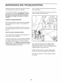
HOW TO ADJUST THE REED SWITCH
If the console does not display correct feedback, the
reed switch should be adjusted.
To adjust the reed switch, see EXPLODED DRAWING
A on page 26. Remove the M4 x 16mm Screws (47)
and the M4 x 25mm Screws (41) from the Left and
Right Shields (17, 18). Make sure to note which size
of Screw you remove from each hole. Then, gently
move the Right Shield out of the way.
Next, rotate the Pulley (24) until a Magnet (38) is
aligned with the Reed Switch (43). Slide the Reed
Switch slightly toward or away from the Magnet. Then,
retighten the M4 x 12mm Screw (31).
Rotate the Pulley (24) for a moment. Repeat these
actions until the console displays correct feedback.
When the reed switch is correctly adjusted, reattach
the shields.
21
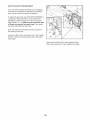
HOW TO ADJUST THE DRIVE BELT
If you can feel the pedals slip while you are pedaling,
even when the resistance is adjusted to the highest
level, the drive belt may need to be adjusted.
To adjust the drive belt, see EXPLODED DRAWING A
on page 26. Remove the M4 x 16mm Screws (47)
and the M4 x 25mm Screws (41) from the Left and
Right Shields (17, 18). Make sure to note which size
of Screw you remove from each hole. Then, gently
move the Left Shield out of the way.
Note: For clarity, the left shield is shown removed in
the drawing at the right.
Loosen the M6 x 20mm Hex Screw (46). Then, tighten
the M10 x 50mm Hex Screw (66) until the Drive Belt
(35) is tight.
\
When the Drive Belt (35) is tight, tighten the M6 x
20mm Hex Screw (46). Then, reattach the shields.
22
EXERCISE GUiDELiNES
Burning Fat--To burn fat effectively, you must exercise at a low intensity level for a sustained period of
time. During the first few minutes of exercise, your
body uses carbohydrate calories for energy. Only after
the first few minutes of exercise does your body begin
to use stored fat calories for energy. If your goal is to
burn fat, adjust the intensity of your exercise until your
heart rate is near the lowest number in your training
zone. For maximum fat burning, exercise with your
heart rate near the middle number in your training
zone.
Aerobic Exercise-- If your goal is to strengthen your
cardiovascular system, you must perform aerobic
exercise, which is activity that requires large amounts
of oxygen for prolonged periods of time. For aerobic
exercise, adjust the intensity of your exercise until your
heart rate is near the highest number in your training
These guidelines will help you to plan your exercise
program. For detailed exercise information, obtain a
reputable book or consult your physician. Remember,
proper nutrition and adequate rest are essential for
successful results.
zone.
WORKOUT
EXERCISE iNTENSITY
Warming Up--Start with 5 to 10 minutes of stretching and light exercise. A warm-up increases your body
temperature, heart rate, and circulation in preparation
for exercise.
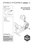
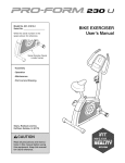
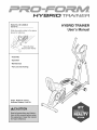
Whether your goal is to burn fat or to strengthen your
cardiovascular system, exercising at the proper intensity is the key to achieving results. You can use your
heart rate as a guide to find the proper intensity level.
The chart below shows recommended heart rates for
Training Zone Exercise--Exercise
for 20 to 30 minutes with your heart rate in your training zone. (During
the first few weeks of your exercise program, do not
keep your heart rate in your training zone for longer
than 20 minutes.) Breathe regularly and deeply as you
exercise; never hold your breath.
fat burning and aerobic exercise.
165
155
145
140
130
125
115
_W_
I45
138
130
125
118
110
103
q,_)
125
120
115
110
105
95
gO
20
30
40
50
60
70
GUIDELINES
W
Cooling Down--Finish with 5 to 10 minutes of stretching. Stretching increases the flexibility of your muscles
and helps to prevent post-exercise problems.
80
EXERClSE FREQUENCY
To find the proper intensity level, find your age at the
bottom of the chart (ages are rounded off to the nearest ten years). The three numbers listed above your
age define your "training zone." The lowest number is
the heart rate for fat burning, the middle number is the
heart rate for maximum fat burning, and the highest
number is the heart rate for aerobic exercise.
To maintain or improve your condition, complete three
workouts each week, with at least one day of rest
between workouts. After a few months of regular exercise, you may complete up to five workouts each week,
if desired. Remember, the key to success is to make
exercise a regular and enjoyable part of your everyday
life.
23
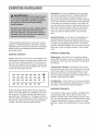
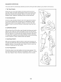
SUGGESTED
STRETCHES
The correct form for several basic stretches is shown at the right. Move slowly as you stretch; never bounce.
1. Toe Touch Stretch
Stand with your knees bent slightly and slowly bend forward from
your hips. Allow your back and shoulders to relax as you reach down
toward your toes as far as possible. Hold for 15 counts, then relax.
Repeat 3 times. Stretches: Hamstrings, back of knees and back.
2. Hamstring
Stretch
Sit with one leg extended. Bring the sole of the opposite foot toward
you and rest it against the inner thigh of your extended leg. Reach
toward your toes as far as possible. Hold for 15 counts, then relax.
Repeat 3 times for each leg. Stretches: Hamstrings, lower back and
groin.
3. Calf/Achilles
Stretch
With one leg in front of the other, reach forward and place your hands
against a wall. Keep your back leg straight and your back foot flat on
the floor. Bend your front leg, lean forward and move your hips toward
the wall. Hold for 15 counts, then relax. Repeat 3 times for each leg.
To cause further stretching of the achilles tendons, bend your back leg
as well. Stretches: Calves, achilles tendons and ankles.
4. Quadriceps
Stretch
With one hand against a wall for balance, reach back and grasp one
foot with your other hand. Bring your heel as close to your buttocks as
possible. Hold for 15 counts, then relax. Repeat 3 times for each leg.
Stretches: Quadriceps and hip muscles.
5. inner Thigh Stretch
Sit with the soles of your feet together and your knees outward. Pull
your feet toward your groin area as far as possible. Hold for 15 counts,
then relax. Repeat 3 times. Stretches: Quadriceps and hip muscles.
5
24
f
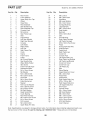
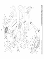
PART LIST
Key No. Qty.
Model No. 831.23880.0 R0913A
Description
Key No. Qty.
Description
1
2
3
4
5
6
7
8
9
10
11
12
1
1
2
2
2
1
2
2
1
16
4
1
Rear Frame
Front Stabilizer
Upper Body Arm Cap
Wheel
Snap Ring
Rear Stabilizer
Seat Handle Cap
Rear Stabilizer Cap
Console Knob
M8 Locknut
Seat Frame Cap
Seat
51
52
53
54
55
56
57
58
59
60
61
62
4
8
1
6
8
4
2
2
2
1
1
1
M6 Locknut
M6 x 38mm Bolt
Handlebar
M8 Large Washer
M4 x 5mm Screw
Carriage Bushing
Large Bumper
M8 x 125mm Bolt
Seat Handle
Backrest
M10 x 60mm Bolt
Idler
13
14
15
16
17
18
19
20
21
22
23
2
1
1
1
1
1
2
2
1
1
1
Leg Bushing
Left Seat Bracket
Right Seat Bracket
Console
Left Shield
Right Shield
Leg Cap
Seat Frame Cap
Crank
Clamp
Front Frame
63
64
65
66
67
68
69
70
71
72
73
14
1
1
1
2
2
6
2
1
2
1
Pivot Bushing
Right Pedal Carriage
Left Pedal Carriage
M10 x 50mm Hex Screw
Pedal
Pulse Grip/Pulse Wire
Small Bumper
Pedal Knob
Right Pedal Leg
Crank Arm
Console Post
24
25
26
27
28
29
30
31
32
33
34
35
36
37
38
39
40
41
42
43
44
45
46
47
48
49
50
1
4
2
1
1
1
1
7
9
2
10
1
8
1
2
3
4
5
12
1
2
1
1
17
5
4
2
Pulley
M6 Curved Washer
Seat Handle Grip
Water Bottle Holder
Idler Screw
Front Frame Bumper
Resistance Motor
M4 x 12mm Screw
M6 Washer
M10 x 98mm Bolt
M8 x 20mm Screw
Drive Belt
M8 x 10mm Screw
Eddy Mechanism
Magnet
M10 Curved Washer
M10 x 65mm Screw
M4 x 25mm Screw
M8 Split Washer
Reed Switch/Wire
Crank Bearing
Main Wire Harness
M6 x 20mm Hex Screw
M4 x 16mm Screw
M10 Locknut
M6 x 30mm Bolt
Upper Body Arm Grip
74
75
76
77
78
79
80
81
82
83
84
85
86
87
88
89
90
91
92
93
94
95
96
97
98
*
1
1
1
2
2
1
1
6
2
6
2
2
1
2
1
1
6
1
1
4
2
6
1
1
2
-
Left Upper Body Leg
Right Pedal Leg Bracket
Left Pedal Leg Bracket
Crank Arm Screw
Crank Arm Cap
Left Pedal Leg
Axle
Wave Washer
Upper Body Arm Cover
M8 x 40mm Bolt
Pedal Plate
Pedal Brace
Right Upper Body Leg
M10 x 102mm Bolt
Right Upper Body Arm
Left Upper Body Arm
Pivot Cover
Ground Screw
M4 x 10mm Screw
M8 Small Washer
M8 x 65mm Bolt
M8 x 13mm Screw
M10 x 25mm Screw
M10 x 54mm Screw
M10 Split Washer
User's Manual
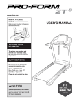
Note: Specifications are subject to change without notice. For information about ordering replacement parts, see
the back cover of this manual. If a part is missing, call 1-888-533-1333. *These parts are not illustrated.
25
m
12
X
92
"U
29
r""
0
32
m
i
11
27
52
._32
52
_
93
52 _"¢""
_
35
4
45
m
Z
37
23
97
\.
38
20_
40
41
21
18
5
26
93
47---_
t
6
,.-
o
cz.
(D
,F_91,
t
_51
.
Z
1\
o
41
43
25
oo
co
7
59
49
41
47
"_----41
i,o
O3
(30
(30
0
33
o
_o
._&
co
3>
X
"U
r"
68
\
0
53\
81
m
Z
¢)
47
67
39
W
9
63
t,O
",,4
79
I
63
67
81
63
76
90
o
o_
(D
48
86
56
¼
81
75
72
31
85
4
oo
co
81
d
"--'"
Z
o
56
63
34
13
i,o
O3
{30
(30
0
33
o
_o
._&
55
70
_33
co
3>
Your Home
For repair--in
or heating
iiiiiiiiiiiiii
your home--of
all major brand appliances,
and cooling systems, no matter who made
iiiiiiiiiiiiiiiiiiiiiiiiiiiiiiiii
For the replacement
iiiiiiiiiiiiii
iiiiiiiiiiiiii
iiiiiiiiiiiiii
iiiiiiiiiiiiii
iiiiiiiiiiiiii
iiiiiiiiiiiiii
iiiiiiiiiiiiii
parts, accessories,
lawn and garden equipment,
it, no matter who sold it!
and user's manuals that you need to do-it-yourself.
For Sears professional
installation of home appliances
and items like garage door openers and water heaters.
1-800-4-MY-HOME
® (1-800-469-4663)
Call anytime, day or night (U.S.A. and Canada)
www.sears.com
www.sears.ca
Our Home
For repair of carry-in items like vacuums, lawn equipment,
and electronics, call or go on-line for the location of your nearest
Sears Parts & Repair Center.
1-800-488-1222
Call anytime, day or night (U.S.A. only)
www.sears.com
To purchase a protection agreement (U.S.A.)
or maintenance agreement (Canada) on a product serviced by Sears:
1-800-827-6655
(U.S.A.)
1-800-361-6665
(Canada)
Para pedir servicio de reparaci6n a domicilio, y para ordenar piezas:
...................................................
....
1-888-SU-HOGAR
®(1-888-784-6427)
Se r,
® Registered Trademark / TMTrademark / SMService Mark of Sears Brands, LLC
® Marca Registrada / TMMarca de F&brica / SMMarca de Servicio de Sears Brands, LLC
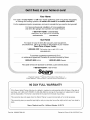
90 DAY FULL WARRANTY
If this Sears Hybrid Trainer fails due to a defect in material or workmanship within 90 days of the date of
purchase, call 1-800-4-MY-HOME® (1-800-469-4663) to arrange for free repair (or replacement if repair
proves impossible). The frame is warranted for 5 years from the date of purchase.
This warranty does not apply when the Hybrid Trainer is used commercially or for rental purposes.
This warranty gives you specific legal rights, and you may also have other rights which vary from state to
state.
Sears, Roebuck and Co., Hoffman Estates, IL 60179
J
,%
Part No. 345486 R0913A
t-/
Printed in China © 2013 ICON IP, Inc.