1
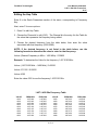
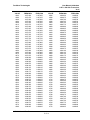
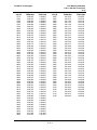
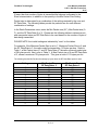
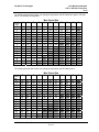
FreeWave Technologies
User Manual Addendum
1.427-1.432 GHz Transceiver
V1.0f
FreeWave Technologies Inc.
1.427 – 1.432 GHz User Manual Addendum
(LRS-140CSU)
The FreeWave Technologies LRS Family 1.427–1.432 GHz Licensed Radios operate
in substantially the same manner as the 900 MHz and 2.4 GHz transceivers. They
can be used in point to point and multipoint modes, with essentially the same
parameter options.
UL Certification
LRS-140CSU:
“This equipment is suitable for use in Class I, Division 2, Groups A, B, C, and D or
non-hazardous locations only.”
“Warning – Explosion Hazard – Substitution of components may impair suitability for
Class I, Division 2.”
The diagnostics port and cable do not have a latching connector and cannot be used
in a hazardous location.
GENERAL:
The device covered by this Report is a wireless data transceiver. It must be installed
in a suitable enclosure.
RATINGS:
Model LRS-140CSU is supplied by a NEC Class 2 Power Supply.
6 V dc to 30 V dc at 500 mA (Avg) @ 115.2K bd max.
The ambient rating is -20°C to 40°C.
Conditions of Acceptability – When installed in the end use equipment, the
following considerations are to be examined:
1. The transceivers shall be mounted within an enclosure which is suitable for the
intended application. The enclosure shall also have provisions for Division 2
wiring methods as specified in the National Electrical Code or Canadian
Electrical Code, as applicable.
2. The transceivers must be used within their Recognized ratings and
transmission rate.
3. Installations and use should be in accordance with the National Electrical
Code or Canadian Electrical Code, as applicable.
LAD0012AA v1.0 Rev F
1 of 10
FreeWave Technologies
User Manual Addendum
1.427-1.432 GHz Transceiver
V1.0f
4. The end product shall be marked with a warning for the end user indicating
that changes to the baud rate may impair the safety characteristics for Class I,
Division 2 Hazardous Locations.
5. The suitability of field wiring connections shall be determined in the end use
application.
6. The devices were evaluated for use in 40°C ambient, use of these devices
above 40°C may require additional testing.
7. The diagnostics port and cable do not have a latching connector and cannot
be used in a hazardous location.
Quick Start on a Point-to-Multipoint System
The following is a quick start guide for setting up two transceivers in Point-toMultipoint mode. This mode allows for a Master to communicate with several Slaves
simultaneously. In addition to the Quick Start Guide, detailed instructions on how to
set up the frequency and min and max packet sizes are also provided.
NOTE: The following is a step by step procedure for radio setup through
HyperTerminal. The device may also be setup via EZConfig. When using EZConfig,
please reference the tables in this procedure for proper radio configuration.
1. Connect the transceiver to the serial port of a computer either through a data
cable (9 pin serial) or via the diagnostics cable.
2. Open up a HyperTerminal session.
• Use the following settings in connecting with HyperTerminal
• Connect to COMx (the COM port to which the cable is connected)
• Set; Bits per second to 19200, Data bits- 8, Parity- None, Stop bits- 1, Flow
control- None.
3. Press the setup button next to the serial port on the radio. If the diagnostics
cable is being used, press Shift-U (capital U).
• The three lights on the board should all turn green, indicating Setup mode.
• The main menu will appear on the screen.
4. Press 0 to get into the Operation Mode menu.
• Press 2 to set the radio as a point to Multipoint Master.
• Press 3 to set the radio as a point to Multipoint Slave.
• Press Esc to get back to Main menu.
5. Press 1 in the main menu to change the Baud Rate.
• The baud rate in setup mode will default to 19200.
• The baud rate must be changed to match the baud rate of the device that the
radio is attached to.
6. At the Main Menu, press 3.
LAD0012AA v1.0 Rev F
2 of 10
FreeWave Technologies
•
•
•
•
•
•
•
User Manual Addendum
1.427-1.432 GHz Transceiver
V1.0f
All of the following settings must be the same on all radios throughout the
network.
FreqKey- This setting is discussed later in this manual.
Max Packet Size-This setting is discussed later in this manual.
Min Packet Size- This setting is discussed later in this manual.
RF Data Rate- The LRS Licensed Radio can be configured to operate at one
of two available throughputs. To adjust this setting, enter 4, RF Data Rate, in
the Radio Parameters Menu. (Available settings are 2 or 3.)
For Maximum Throughput of 9.6 Kbps at 2 Level GFSK, RF Data Rate= 3.
For Maximum Throughput of 19.2 Kbps at 4 Level GFSK, RF Data Rate=2.
7. At the Main Menu, press 5.
• Number Repeaters should be set to 0.
• Set the Network ID value to any value between 1 and 4095, except 255.
• Make sure this value is the same on every radio in the network.
Operation in Single Frequency Mode
Note: It is imperative that all transceivers used in a network are set to identical
frequency parameters.
To set the frequency to be used, enter the Radio Parameters section of the
transceiver setup from the Main Menu, as shown below:
LAD0012AA v1.0 Rev F
3 of 10
FreeWave Technologies
User Manual Addendum
1.427-1.432 GHz Transceiver
V1.0f
Editing the Hop Table
Enter 0 in the Radio Parameters section of the menu, corresponding to Frequency
Key.
Next, enter F for more options.
1. Enter 0 to edit Hop Table.
2. Choose the Channel # to edit (0-63). The Channel # is the entry # in the Table for
the value that represents the frequency being edited.
3. Choose the desired frequency from the table below, then enter the value
associated with that frequency (4320-5280).
NOTE: If the desired frequency is not listed in the table below, use the
following formula to determine the value to enter for that frequency:
Value= (Desired Frequency in MHz – 1400 MHz) / 0.00625
Example: To determine the Value for the frequency 1.427.0125 MHz:
Value= (1427.0125 MHz – 1400 MHz) / 0.00625
Value= 27.0125 / 0.00625
Value= 4322
Enter the value 4322 to use the frequency 1.4270125 GHz
1.427-1.432 GHz Frequency Table
VALUE
4320
4324
4328
4332
4336
4340
4344
4348
4352
FREQ MHz
1427.000
1427.025
1427.050
1427.075
1427.100
1427.125
1427.150
1427.175
1427.200
FREQ GHz
1.427000
1.427025
1.427050
1.427075
1.427100
1.427125
1.427150
1.427175
1.427200
VALUE
4356
4360
4364
4368
4372
4376
4380
4384
4388
LAD0012AA v1.0 Rev F
4 of 10
FREQ MHz
1427.225
1427.250
1427.275
1427.300
1427.325
1427.350
1427.375
1427.400
1427.425
FREQ GHz
1.427225
1.427250
1.427275
1.427300
1.427325
1.427350
1.427375
1.427400
1.427425
FreeWave Technologies
VALUE
4392
4396
4400
4404
4408
4412
4416
4420
4424
4428
4432
4436
4440
4444
4448
4452
4456
4460
4464
4468
4472
4476
4480
4484
4488
4492
4496
4500
4504
4508
4512
4516
4520
4524
4528
4532
4536
4540
4544
4548
4552
4556
4560
4564
4568
4572
4576
4580
FREQ MHz
1427.450
1427.475
1427.500
1427.525
1427.550
1427.575
1427.600
1427.625
1427.650
1427.675
1427.700
1427.725
1427.750
1427.775
1427.800
1427.825
1427.850
1427.875
1427.900
1427.925
1427.950
1427.975
1428.000
1428.025
1428.050
1428.075
1428.100
1428.125
1428.150
1428.175
1428.200
1428.225
1428.250
1428.275
1428.300
1428.325
1428.350
1428.375
1428.400
1428.425
1428.450
1428.475
1428.500
1428.525
1428.550
1428.575
1428.600
1428.625
User Manual Addendum
1.427-1.432 GHz Transceiver
V1.0f
FREQ GHz
1.427450
1.427475
1.427500
1.427525
1.427550
1.427575
1.427600
1.427625
1.427650
1.427675
1.427700
1.427725
1.427750
1.427775
1.427800
1.427825
1.427850
1.427875
1.427900
1.427925
1.427950
1.427975
1.428000
1.428025
1.428050
1.428075
1.428100
1.428125
1.428150
1.428175
1.428200
1.428225
1.428250
1.428275
1.428300
1.428325
1.428350
1.428375
1.428400
1.428425
1.428450
1.428475
1.428500
1.428525
1.428550
1.428575
1.428600
1.428625
VALUE
4584
4588
4592
4596
4600
4604
4608
4612
4616
4620
4624
4628
4632
4636
4640
4644
4648
4652
4656
4660
4664
4668
4672
4676
4680
4684
4688
4692
4696
4700
4704
4708
4712
4716
4720
4724
4728
4732
4736
4740
4744
4748
4752
4756
4760
4764
4768
4772
LAD0012AA v1.0 Rev F
5 of 10
FREQ MHz
1428.650
1428.675
1428.700
1428.725
1428.750
1428.775
1428.800
1428.825
1428.850
1428.875
1428.900
1428.925
1428.950
1428.975
1429.000
1429.025
1429.050
1429.075
1429.100
1429.125
1429.150
1429.175
1429.200
1429.225
1429.250
1429.275
1429.300
1429.325
1429.350
1429.375
1429.400
1429.425
1429.450
1429.475
1429.500
1429.525
1429.550
1429.575
1429.600
1429.625
1429.650
1429.675
1429.700
1429.725
1429.750
1429.775
1429.800
1429.825
FREQ GHz
1.428650
1.428675
1.428700
1.428725
1.428750
1.428775
1.428800
1.428825
1.428850
1.428875
1.428900
1.428925
1.428950
1.428975
1.429000
1.429025
1.429050
1.429075
1.429100
1.429125
1.429150
1.429175
1.429200
1.429225
1.429250
1.429275
1.429300
1.429325
1.429350
1.429375
1.429400
1.429425
1.429450
1.429475
1.429500
1.429525
1.429550
1.429575
1.429600
1.429625
1.429650
1.429675
1.429700
1.429725
1.429750
1.429775
1.429800
1.429825
FreeWave Technologies
VALUE
4776
4780
4784
4788
4792
4796
4800
4804
4808
4812
4816
4820
4824
4828
4832
4836
4840
4844
4848
4852
4856
4860
4864
4868
4872
4876
4880
4884
4888
4892
4896
4900
4904
4908
4912
4916
4920
4924
4928
4932
4936
4940
4944
4948
4952
4956
4960
4964
FREQ MHz
1429.850
1429.875
1429.900
1429.925
1429.950
1429.975
1430.000
1430.025
1430.050
1430.075
1430.100
1430.125
1430.150
1430.175
1430.200
1430.225
1430.250
1430.275
1430.300
1430.325
1430.350
1430.375
1430.400
1430.425
1430.450
1430.475
1430.500
1430.525
1430.550
1430.575
1430.600
1430.625
1430.650
1430.675
1430.700
1430.725
1430.750
1430.775
1430.800
1430.825
1430.850
1430.875
1430.900
1430.925
1430.950
1430.975
1431.000
1431.025
User Manual Addendum
1.427-1.432 GHz Transceiver
V1.0f
FREQ GHz
1.429850
1.429875
1.429900
1.429925
1.429950
1.429975
1.430000
1.430025
1.430050
1.430075
1.430100
1.430125
1.430150
1.430175
1.430200
1.430225
1.430250
1.430275
1.430300
1.430325
1.430350
1.430375
1.430400
1.430425
1.430450
1.430475
1.430500
1.430525
1.430550
1.430575
1.430600
1.430625
1.430650
1.430675
1.430700
1.430725
1.430750
1.430775
1.430800
1.430825
1.430850
1.430875
1.430900
1.430925
1.430950
1.430975
1.431000
1.431025
VALUE
4968
4972
4976
4980
4984
4988
4992
4996
5000
5004
5008
5012
5016
5020
5024
5028
5032
5036
5040
5044
5048
5052
5056
5060
5064
5068
5072
5076
5080
5084
5088
5092
5096
5100
5104
5108
5112
5116
5120
LAD0012AA v1.0 Rev F
6 of 10
FREQ MHz
1431.050
1431.075
1431.100
1431.125
1431.150
1431.175
1431.200
1431.225
1431.250
1431.275
1431.300
1431.325
1431.350
1431.375
1431.400
1431.425
1431.450
1431.475
1431.500
1431.525
1431.550
1431.575
1431.600
1431.625
1431.650
1431.675
1431.700
1431.725
1431.750
1431.775
1431.800
1431.825
1431.850
1431.875
1431.900
1431.925
1431.950
1431.975
1432.000
FREQ GHz
1.431050
1.431075
1.431100
1.431125
1.431150
1.431175
1.431200
1.431225
1.431250
1.431275
1.431300
1.431325
1.431350
1.431375
1.431400
1.431425
1.431450
1.431475
1.431500
1.431525
1.431550
1.431575
1.431600
1.431625
1.431650
1.431675
1.431700
1.431725
1.431750
1.431775
1.431800
1.431825
1.431850
1.431875
1.431900
1.431925
1.431950
1.431975
1.432000
FreeWave Technologies
User Manual Addendum
1.427-1.432 GHz Transceiver
V1.0f
Programming Single Frequency Mode
To operate the transceiver in single frequency mode enter a 0 in the Radio
Parameters section of the menu, corresponding to Frequency Key.
Next, enter F for more.
1. Enter 1 to program the transceiver to operate in single frequency mode.
2. When prompted enter the number of the frequency to be used:
Enter New Frequency Channel (0-63).
3. Once the single frequency has been entered it will appear at the bottom of the
table as the Single Channel being used. In addition, the FreqKey in the Radio
Parameters menu will now be programmed as Single Channel. As shown below.
In this example, the
radio is programmed
to transmit and
receive at Frequency
1.430781 GHz. This
is understood because
the Single Channel
being used is 45.
Channel 45 has a
value of 4925. 4925=
1.430781 GHz.
Min/Max Packet Sizes
Min/Max Packet Sizes allow the user to designate the size in bytes of the packets
used by the transceiver in its communication link. This may be of particular value
when using FreeWave with different communications software packages. In addition,
packet sizes should be changed for every network, especially when overlapping or
adjacent networks are installed.
The combination of Max and Min Packet Size settings determines the allocation of
the communication link from the Master to the Slave and vice versa. With a given
Max Packet Setting the Master will transmit up to that number of bytes on every hop.
LAD0012AA v1.0 Rev F
7 of 10
FreeWave Technologies
User Manual Addendum
1.427-1.432 GHz Transceiver
V1.0f
If fewer than that number of bytes is transmitted the balance is allocated to the
Slave’s transmission, in addition to the quantity in the Min Packet Size Setting.
Packet size is determined by a combination of the settings entered by the user and
RF Data Rate. The following tables provide the packet sizes for each different
combination of settings.
In the Radio Parameters menu, enter the Min Packet size (0-F), Max Packet size (0F), and the RF Data Rate (2 or 3). Please see the following tables to determine min
and max packet sizes and RF Data Rate to be used based on the number of bytes of
data being transmitted.
PLEASE NOTE: the invalid settings as indicated by “xxxx” on the tables.
For example, if the Minimum Packet Size is set to 7, Maximum Packet Size to 6, and
the RF Data Rate to 3, the radio would be transmitting 110 bytes per hop. Refer to
Table 1; a Min Packet size of 7 and RF Data Rate of 3 shows a minimum packet size
of 38 bytes per slot. Next, refer to Table 3. A Max Packet size of 6 and RF Data Rate
of 3, shows a maximum 72 bytes per slot. This gives a total of 110 bytes per slot.
The following lists the Min Packet size settings by bytes when the RF Data Rate equals 2 and 3.
Setting
0
1
2
3
4
5
6
7
8
9
A
B
C
D
E
F
Min Packet Size
RF Data Rate= 2
36
41
47
53
59
64
70
76
81
87
93
98
104
110
115
121
Min Packet Size
RF Data Rate= 3
18
20
23
26
29
32
35
38
40
43
46
49
52
55
57
60
Table 1
LAD0012AA v1.0 Rev F
8 of 10
FreeWave Technologies
User Manual Addendum
1.427-1.432 GHz Transceiver
V1.0f
The following lists the Max Packet size settings by bytes when the RF Data Rate equals 2. RF data
rate of 2 is currently not supported.
Min
Packet
Size
0
1
0
1
2
3
4
5
6
7
8
9
A
B
C
D
E
F
36
41
47
53
59
64
70
76
81
87
93
98
104
110
115
121
47
53
59
64
70
76
81
87
93
98
104
110
115
121
127
132
2
3
Max Packet Size
4
5
6
59
70
81
64
76
87
70
81
93
76
87
98
81
93
104
87
98
110
93 104 115
98 110 121
104 115 127
110 121 132
115 127 138
121 132 144
127 138 xxxx
132 144 xxxx
138 xxxx xxxx
144 xxxx xxxx
93
98
104
110
115
121
127
132
138
144
xxxx
xxxx
xxxx
xxxx
xxxx
xxxx
104
110
115
121
127
132
138
144
xxxx
xxxx
xxxx
xxxx
xxxx
xxxx
xxxx
xxxx
7
8
9
A
115
121
127
132
138
144
xxxx
xxxx
xxxx
xxxx
xxxx
xxxx
xxxx
xxxx
xxxx
xxxx
127
132
138
144
xxxx
xxxx
xxxx
xxxx
xxxx
xxxx
xxxx
xxxx
xxxx
xxxx
xxxx
xxxx
138
144
xxxx
xxxx
xxxx
xxxx
xxxx
xxxx
xxxx
xxxx
xxxx
xxxx
xxxx
xxxx
xxxx
xxxx
xxxx
xxxx
xxxx
xxxx
xxxx
xxxx
xxxx
xxxx
xxxx
xxxx
xxxx
xxxx
xxxx
xxxx
xxxx
xxxx
Table 2
The following lists the Max Packet size settings by bytes when the RF Data equals 3.
Min
Packet
Size
0
1
2
3
0
1
2
3
4
5
6
7
8
9
A
B
C
D
E
F
18
20
23
26
29
32
35
38
40
43
46
49
52
55
57
60
23
26
29
32
35
38
40
43
46
49
52
55
57
60
63
66
29
32
35
38
40
43
46
49
52
55
57
60
63
66
69
72
35
38
40
43
46
49
52
55
57
60
63
66
69
72
xxxx
xxxx
Max Packet Size
4
5
6
40
43
46
49
52
55
57
60
63
66
69
72
xxxx
xxxx
xxxx
xxxx
46
49
52
55
57
60
63
66
69
72
xxxx
xxxx
xxxx
xxxx
xxxx
xxxx
52
55
57
60
63
66
69
72
xxxx
xxxx
xxxx
xxxx
xxxx
xxxx
xxxx
xxxx
7
8
9
A
57
60
63
66
69
72
xxxx
xxxx
xxxx
xxxx
xxxx
xxxx
xxxx
xxxx
xxxx
xxxx
63
66
69
72
xxxx
xxxx
xxxx
xxxx
xxxx
xxxx
xxxx
xxxx
xxxx
xxxx
xxxx
xxxx
69
72
xxxx
xxxx
xxxx
xxxx
xxxx
xxxx
xxxx
xxxx
xxxx
xxxx
xxxx
xxxx
xxxx
xxxx
xxxx
xxxx
xxxx
xxxx
xxxx
xxxx
xxxx
xxxx
xxxx
xxxx
xxxx
xxxx
xxxx
xxxx
xxxx
xxxx
Table 3
LAD0012AA v1.0 Rev F
9 of 10
FreeWave Technologies
User Manual Addendum
1.427-1.432 GHz Transceiver
V1.0f
Firmware Errata Notes:
•
Version 9.36C
o Point to Point repeaters not currently supported
o Point to Multipoint repeaters not currently supported
o Low Power mode not currently supported
o RF Data Rate of 2 not currently supported
LAD0012AA v1.0 Rev F
10 of 10