1
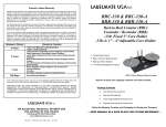
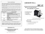
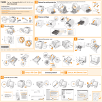
Product Limited Warranty
Labelmate USA warrants to the original end-user customer that Labelmate USA products will be free from
defects in materials and workmanship for the duration described herein below. Labelmate USA’s Limited
Warranty covers only those defects that arise as a result of normal use of the products and does not cover
any other problems, including those that arise as a result of: (i) improper maintenance or modification; (ii)
parts or supplies not provided or supported by Labelmate USA; (iii) operation outside the products’
specifications; or (iv) unauthorized repair, modification or misuse. Use of any unauthorized accessory or
attachment will void coverage.
LABELMATE USA LLC
RRS-8-12 & RRS-8-16
The Warranty period for all products commences the date of shipment from Labelmate USA and accrues to
the original end-user customer. Warranty coverage is non-transferable and terminates immediately upon
rental, resale or any other change in ownership. Original purchase documentation should be retained for
Warranty coverage verification.
In the event Labelmate USA substantiates, during the applicable Warranty period, a defect in any product
which is covered by Labelmate USA’s Warranty, Labelmate USA shall repair or replace the product, at
Labelmate USA’s option. Labelmate USA retains sole discretion to determine whether or not a product is
defective. In no event shall Labelmate USA have any obligation to repair or replace until the customer
returns the defective product to Labelmate USA. The customer assumes any and all responsibility and
liability associated with transportation of products for service under this Warranty.
WARRANTY PERIOD
3-Years
1-Year
180-Days
Label Splicing System
• Dual 12” or 16” diameter x 8”
width Rewinder / Unwinder Drive
Units with independent Direction
and Torque Controls for
maximum bi-directional control
over label web tension.
PRODUCTS COVERED
Label Splicing System, excluding the Power Supply Module
and the Counter Module.
Power Supply Modules
Counter Modules
Any other products or parts not specified herein
Out-of-Warranty Repairs
In the event your product requires service or you have questions regarding Warranty coverage, please call
toll-free (877) 833-7149 inside the United States, or +1 (702) 435-8535 outside the United States.
• Constant Adjustable Torque™
"CAT-3" technology.
• Stainless steel 8” x 16” Splicing
RRS-8-12
Platen with 90º and 75º Blade
Guides
• Convenient Splicing Tape
Dispenser and Alert Label Roll
Holder
• Digital Label Counter with dual
Label Sensors and Pre-set Stopon-Count feature.
LABELMATE USA MAKES NO OTHER WARRANTY OF ANY KIND, WHETHER EXPRESS OR IMPLIED
WARRANTIES OR CONDITIONS OF MERCHANTABILITY, SATISFACTORY QUALITY, AND/OR
FITNESS FOR A PARTICULAR PURPOSE. NO OTHER PERSON, AGENT, DEALER OR RESELLER IS
AUTHORIZED TO GIVE ANY WARRANTIES ON BEHALF OF LABELMATE. ANY OBLIGATION TO
WARRANTY OTHER THAN THAT SPECIFICALLY ADDRESSED HEREIN IS EXPRESSLY DISCLAIMED.
RRS-8 Control Panel Detail
Package Contents
LABELMATE USA LLC
12A Sunset Way, Henderson, NV 89014 USA
(702) 435-8535 FAX (702) 435-8536
Toll-Free (877) 833-7149 in USA!
[email protected]
www.labelmateusa.com
•
•
•
•
•
•
•
User Manual (this document).
Splicing System Chassis with two Rewind / Unwind Drive Units.
Two Locking Bars to affix the system together in alignment.
Universal Power Supply Module 100-230V 50-60Hz with Power Cord.
2 each “Quick Chuck” Label Core Holders with Inner and Outer Flange Plates
Allen Wrench for “Quick-Chucks”.
Outer retaining Ring and Flange Plate for Alert Label Roll Holder.
WARNING
This product is for indoor use only.
Not for use in wet locations.
Unplug the unit before performing any cleaning or
maintenance services.
SETUP
1. Using the Screws provided, attach an Inner Flange Plate to each of the
“Quick-Chuck” Core Holders in the shaft end of the “Quick-Chucks.” The
smooth side of the Flange faces the Red Lock Knob end of the Shaft.
2. Slide a “Quick-Chuck” over each of the Motor Shafts being careful to align
the Set Screw in the “Quick-Chuck” with the flat area of the Motor Shaft.
Position the “Quick-Chuck” on the Shaft so that the front surface of the
Flange exactly lines up with the front surface of the vertical Chassis Plate.
3. Tighten each “Quick-Chuck” Set Screw snugly to the Motor Shaft using the
Allen Wrench provided.
4. Using the screws provided, attach a Locking Bar between each of the
Rewind/Unwind Drive Units and the Splicer Transport.
5. Affix the red Alert Label Roll Holder to the hole in the upper left corner of the
vertical Chassis Plate. You can use either the provided complete Label Roll
Flange with Hub or the Ring by itself to retain the Alert Label Roll on the Roll
Holder. The Spring Ball can be adjusted to control tightness.
6. Plug the Output Plug from the Power Supply into the “DC IN” Jack on the
bottom of the Control Panel Box. The Cables to the Left and Right Drive
Units are already plugged into the bottom of the Control Panel.
7. Plug the AC Power Cord into the Power Supply and connect it to a suitable
AC wall outlet.
FAMILIARIZATION
1. Left and Right Drive Unit Torque Control Knobs are provided.
2. Left and Right Drive Unit DIRECTION Switches have a “Run Right,” “Run
Left” and a center “OFF” position. This allows the maximum flexibility in
controlling web tension. The Drive Unit being used as the Supply Roll
“Unwinder” can be put in the “OFF” (neutral) position for minimum web
tension, or can be placed in the “reverse” position with a low Torque setting
to provide more web tension.
3. The “STOP / RUN” Switch enables or disables both Drive Units
simultaneously.
4. The Counter Sensor Select Switch selects either the left-hand or the righthand Label Count Sensors (The Sensors detect opaque labels only).
5. The white Counter Reset Button resets the Counter to “zero” and has the
same function as the small Reset (RST) Button on the face of the Counter
Display Module.
6. Rotate both TORQUE Control Knobs to the minimum (fully counterclockwise) position.
7. Place the STOP / RUN Switch in the STOP Position.
8. The Power Switch is located on the left side of the Control Box. Place the
Switch in the “ON” Position.
9. Place “STOP/RUN” Switch in the “RUN” position.
10.Place the RIGHT DRIVE UNIT Direction Switch to the right.
11. Rotate the right TORQUE Control Knob clockwise and observe the righthand Drive Unit “Quick-Chuck” rotates in a clockwise direction and that the
TORQUE Control Knob adjusts the speed.
12. Continue to experiment with the Controls to get familiar with their operation.
13. Observe the position of the Count Sensor Select Switch and manually pass
a label through the Count Sensor and observe the Counter Display
increments.
LABEL SPLICING
1. Normally, the supply roll of labels will be on the left-hand Drive Unit and the
take-up roll will be on the right.
2. Place the supply roll of labels fully onto the left-hand Drive Unit “QuickChuck” and tighten the red Lock Knob snugly.
3. Thread the Label Web under and over the Guide Rollers, across the
stainless-steel Platen and over and under the Guide Rollers on the righthand side of the Unit.
4. Slide an empty label core over the desired Core Holder until the core is
against the inner Flange Plate. Turn the “Quick-Chuck” Lock Knob and affix
the Label Web to the Core.
5. If you wish to enter a pre-set Count where the Splicer will stop when that
number of Labels has been counted, you may do so. At higher speeds the
system may “coast” after the desired count is reached. Simply pull the Label
Web backward through to add the number of Labels “over” to the count. Now
you will be at the desired count.
6. Switch the “STOP/RUN” Switch to STOP.
7. Lower the right-hand Hold Down Clamp onto the Label Web and secure the
Lock Knob.
8. Place the new Label Roll onto the Supply Roll Holder and thread the Labels
under and over the Guide Rollers to where you want the overlapping Splice
to be made.
9. Lower the left-hand Hold Down Clamp onto the Label Web and secure the
Lock Knob.
10. By dragging your sharp Blade down the desired Blade Guide Groove you
can cut through the overlapping Labels.
11.Remove any waste Labels and Label Web.
12. If you wish to apply any Alert Labels do so, otherwise you can use a piece
of Splicing Tape to join the old and new lengths of Labels.
13.Release the Hold-down Clamps.
14.Reset the Counter, if appropriate and place the “STOP/RUN” Switch to
RUN to resume your work.
MAINTENANCE
The RRS-8 Label Splicing System requires no maintenance. If needed, clean the
Counter Display Screen with a moist soft cloth. Do not use any chemicals or
cleaning products as the plastic may be damaged.