1
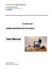
Owner’s Manual
ADDENDUM
TM
FOR ARIA SPA ONLY
The new Aria spa was not available during the printing of the Owner’s Manual. The following additional information will assist in
the operation of the Aria spa. Discard this addendum if you did NOT purchase an Aria spa.
IMPORTANT INFORMATION:
* The Aria spa has the same dimensions as the Vanguard® spa; use pg. 8 for the leveling points.
* The Aria uses one 2.5 HP (Wavemaster® 9000) single speed jet pump and one 2.0 HP (Wavemaster 8200) two speed jet pump.
* The heating system consists of a 4,000 watt (4 kW) No Fault® heater.
* The Aria is equipped with the Moto-Massage® DX, Hydrostream® Jet, and the BellaFontana® water feature.
* The auxiliary control panel jet controls operate in the same method as the Vista® and Envoy® spas.
* The Aria is equipped with a music system.
* The Aria spa uses Tri-X® filters.
Arrows pointing
towards each other
ARIA MUSIC SYSTEM
The Aria sound system includes the following:
• In.tune AM-FM receiver/ MP3/ CD player
• Two Pop-Up rotating Satellite Speakers
• Sub-woofer (located inside spa between shell and removable panel on the back side)
Press button to raise the speaker
IMPORTANT: The User manual for the CD AM/FM Stereo has
been included in the spa’s Owner’s Packet.
SPEAKER OPERATION
Your Aria spa is equipped with two pop-up Satellite speakers.
To operate the pop-up speakers:
1. Press the button next to the speaker.
2. Rotate the speaker to the desired position (the speaker
can rotate in either direction until it stops).
3. The pop-up speaker will only lower in one position. To
lower, rotate the speaker until the two arrows point
towards each other, then press down on the top of the
speaker until it locks into position.
Speaker in initial
raised position.
Rotate speaker in
clockwise direction to
desired location.
Rotate speaker counterclockwise to return to the
initial raised position in
order to lower speaker.
ARIA MUSIC SYSTEM AUXILIARY CONTROL PANEL
The Aria spa has a factory installed music system. The auxiliary panel will allow you to control the volume and the equalization / tone of the stereo.
SOUND CONTROL
For Aria sound control, the “Mode ” button must be pressed followed by the light button to make an audio change. To increase or decrease the volume, first press the “Mode”
button once followed by the LIGHT / VOLUME PLUS (+) or the LIGHT / VOLUME MINUS (-) button as many times as desired (within 5 seconds of each key press) to increase
or decrease the volume of the SpAudio system. The auxiliary panel reverts back to normal function if a key is not pressed within the 5 second time frame. Aria sound control has
15 volume level settings to choose from.
EQUALIZATION / TONE CONTROL
To change the equalization / tone, first press the “Mode” button once followed by the JETS / TONE BUTTON as many times as desired (within 5 seconds of each key press) to
scroll through the pre-selected EQ settings. The auxiliary panel reverts back to normal function if a key is not pressed within the 5 second
Page 1
PN 301044ADD Rev C (010/06)
ARIA™ (AR) WIRING CONNECTIONS
1. Identify the TB-1 terminal block, located inside the control box at the lower left-hand corner.
2.
Connect the #12 AWG, BLUE wire, from the subpanel 20 amp breaker, terminal L1 to TB-1, terminal 1
3.
Connect the #12 AWG, RED wire, from the subpanel 20 amp breaker, terminal L2 to TB-1, terminal 3
NOTE: The WHITE neutral wire must be attached to the LOAD neutral on the 230 volt, 30 amp breaker (not to the neutral bus bar in the subpanel). The WHITE neutral wire
coming from the breaker itself is already connected to the neutral bus bar.
4.
Connect the #10 AWG, BLUE wire, from the subpanel 30 amp breaker, terminal L1 to TB-1, terminal 2
5.
Connect the #10 AWG, RED wire, from the subpanel 30 amp breaker, terminal L2 to TB-1, terminal 4
6.
Connect the #10 AWG, WHITE wire, from the subpanel 30 amp breaker, terminal N (load neutral) to TB-1, terminal 5
7.
Connect the #10 AWG, GREEN wire, from the subpanel GROUND bar to TB-1, system ground terminal.
8.
Using the pressure wire connector provided on the outside of the control box, bond the spa to all exposed metal equipment or fixtures,
handrails, and the concrete pad (if applicable) per N.E.C. and local codes.
9.
Replace the control box cover and securely tighten the fastening screws. Close and secure the equipment compartment door as follows:
• Place top of door or panel directly below bartop against the frame of the spa.
• Push bottom of door or panel against the spa frame.
• Slide door or panel upward (pushing in on center of door) until screw holes line up.
• Slightly pull on door or panel, if door remains against the spa then replace the screws.
• If the door does not lock into position, repeat the previous steps.
WARNING: FILL THE SPA WITH WATER BEFORE TURNING ON THE POWER! (See STARTUP AND REFILL PROCEDURES).
Once your spa has been filled with water, turn it on and test all of the circuit breakers.
NOTE: If both breakers immediately trip, verify that the #10 AWG WHITE neutral wire is connected from TB-1 terminal 5 to the N (load neutral) terminal of the 30 amp
subpanel breaker. Each breaker should be tested prior to each use. Here’s how:
1.
Push the “TEST” button on each GFCI breaker, and observe it click OFF.
2.
Wait 30 seconds, then push the breaker switch to the OFF (down) position (to ensure that it has completely disengaged), then push the
breaker switch to the ON (up) position. If you don't wait 30 seconds, the spa’s control panel may flash four lines on and off – try again.
If any of the GFCI breakers fails to operate in this manner, your spa may have an electrical malfunction, and you may be at risk of electrical shock. Turn off all circuits and do
not use the spa until the problem has been corrected by an authorized service agent.
WARNING: Removing or bypassing any GFCI breaker will result in an unsafe spa and will void the spa’s warranty.
IMPORTANT: Should you ever find the need to move or relocate your Hot Spring® spa, it is essential that you understand and apply these installation requirements. Your Hot
Spring spa has been carefully engineered to provide maximum safety against electric shock. Remember, connecting the spa to an improperly wired circuit will negate many of
its safety features.
NOTE: Long wiring runs may require larger-gauge wire than stated.
Aria (AR)
230 volt permanently connected model
WARNING!
THE EXACT PHYSICAL LOCATION OF THE TERMINALS ON THE GFCI BREAKER
WILL VARY BETWEEN MANUFACTURERS. CONNECTING THE HOT WIRE TO THE
NEUTRAL TERMINAL WILL CAUSE IRREVERSIBLE DAMAGE TO THE CONTROL BOX.
**
GRD
System Ground Terminal
** Refer to NEC 250-122 (table)
NOTE: The wire connections to GFCI breakers are for reference only. Always ensure the white neutral wire is connected to the load neutral of the 30 amp breaker.
*PROVIDED WITH SPA.
NOTE: ALL WIRING SHOULD BE COPPER.
Page 2
PN 301044ADD Rev C (010/06)
™
ARIA
(MODEL AR)
P
OVERHEAD VIEW
A. SmartJet® system lever
B. Precision® jets Comfort Control®
system lever
C. Moto-Massage® jet Comfort
Control system lever
D. Pillow
E. Hydromassage jet with
directional nozzle
F. Hydromassage jet with rotary
nozzle
G. Precision jets
H. HydroStream® jet
I. Soothing Seven® jets
J. JetStream® jet
K. Moto-Massage® DX jet
L. Heater return and spa drain
M. Light lens
N. Filter compartment
O. Main control panel
P. Auxiliary control panel
Q. Cup holder
R. Water feature
S. Water feature lever
T. Pop-up speaker
U. Radio
D
Q
C
G
F
F
H
B
D
G
G
E
Q
E
G
K
B
E
S
Q
I
R
G
L
G
I
J
M
Q
T
E
N
T
A
Q
U
8
O
4
1
1
5
2
3
6
7
EQUIPMENT COMPARTMENT
1.
2.
3.
4.
Wavemaster® jet pump
No-Fault® heater
Silent Flo 5000® circulation pump
IQ 2020™ control box
5.
6.
7.
8.
Ozone injector
Main drain valve
Secondary drain
Bonding terminal
Page 3
PN 301044ADD Rev C (010/06)
Aria (Model AR) Jet System Menu
TM
Jet Pump 1
•
•
•
•
•
4 Precision® jets on left back wall
4 HydroStream® jets on left back wall
1 Directional hydromassage on back wall
1 Moto-Massage® DX jet on right back wall
1 JetStream® jet in FootWell® System
Jet Pump 2 Jet System 1
Jet Pump 2 Jet System 2
SmartJet® lever in the 3 o’clock position
SmartJet lever in the 9 o’clock position
•
•
•
•
•
2 dual port rotary jets on back wall
4 Precision jets above Moto-Massage DX
1 Water Feature
2 Directional hydromassage on front right wall
2 Soothing Seven® jets on left wall
•
•
•
•
•
2 Directional hydromassage on left back wall
1 Water Feature
4 Precision jets in lounge (calf jets)
1 JetStream jet in FootWell System
6 Precision jets on left wall
Fo
Dimotpri
en nt
sio
ns
He
igh
t
Eff
Filt ectiv
er e
ar
He ea
a
( W ter
att
s)
Wa
Ca ter
pa
city
Dry
We
igh
t
Fill
ed
We
igh
t*
De
ad
We
igh
t*
Ele
c
Re tric
qu al
ire
me
nts
SPA SPECIFICATIONS
Aria™
(Model AR)
7'3" x 7'3"
2.21m
x
2.21m
36"
.91 m
325
square
feet
4,000
365
gallons
1,382
litres
789
lbs.
3358
kg.
4,841
lbs.
2,196
kg.
110
lbs. per
square
foot
Page 4
230 volt, 50 amp
Single phase GFCI
protected circuit
CAUTION: Watkins® Manufacturing
Corporation suggests a structural engineer or
contractor be consulted before the spa is
placed on an elevated deck.
* NOTE: The “Filled weight” and “Dead
weight” of the spa includes the weight of
the occupants (assuming an average
occupant weight of 175 lbs).
PN 301044ADD Rev C (010/06)