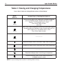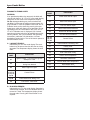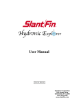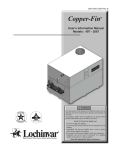
1
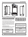
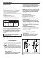
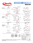
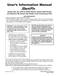
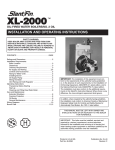
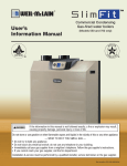
Residential • Gas fired • Hot Water Combi Boilers
User’s Information Manual
Lynx Direct-Vent Sealed Combustion Condensing Combi Boiler
Model LX-120CB, LX-150CB
FOR YOUR SAFETY:
• Before operating this boiler, READ this manual.
• DO NOT attempt to install, service or repair this boiler yourself. There are no user serviceable
parts. Contact a qualified service agency if your boiler needs repair or maintenance. Ask your gas supplier for a
list of qualified service agencies.
• A qualified service agency should inspect the venting system of this boiler on an annual basis.
WARNING: If the information in this manual is
not followed exactly, a fire or explosion may
result causing property damage, personal
injury or loss of life.
__ DO NOT store or use gasoline or other
flammable vapors and liquids in the
vicinity of this or any other appliance.
__ WHAT TO DO IF YOU SMELL GAS
• DO NOT try to light any appliance.
• DO NOT touch any electrical switch
• DO NOT use any phone in your
building.
• Immediately call your gas supplier
from a neighbor’s phone. Follow the
gas supplier’s instructions.
• If you cannot reach your gas supplier,
call the fire department.
__ Installation and service must be performed by
a qualified installer, service agency or the gas
supplier.
Your gas boiler must be installed and serviced by a qualified service agency or gas
supplier. The lack of proper service can result in a dangerous condition.
This manual must be left with owner, hung on or
adjacent to the boiler. Owner should retain manual
for future reference.
Printed in U.S.A. 311
Part No. 81-5012
Publication No. LXCB-UIM
Lynx Combi Boiler
2
3.5
5
"B"
"C"
"A"
33
35
5
"D"
22
LEFT SIDE
L
FRONT
RIGHT SIDE
Figure 1. Dimensions
"A"
WELCOME TO OUR VALUED CUSTOMER
BOILER
You are now the owner of a Slant/Fin Lynx gas-fired boiler,
MODEL
another quality heating product designed and manufactured
6 5/8
3 3/8 LX-120CB
by an industry leader, to provide your family with many years
3 3/4 LX-150CB
of reliable comfort and trouble-free performance. 6 3
The care and maintenance of your new boiler is important to
prevent a hazardous condition which might result form lack
of proper servicing. Therefore, you should perform regular
“owner” inspections as described in this manual (and report
any concerns to a qualified service technician) as well as
have your boiler serviced by a qualified service technician at
least once a year, preferably before the beginning of each
heating season.
LIGHTING INSTRUCTIONS
Locate, read and then follow the procedures on the lighting
instructions label attached to the boiler. For reference, we
have reproduced those instructions in this manual.
"A"
"B"
6 5/8
6 3/8
3 3/8
3 3/4
"C"
2
2 3/4
"D"
16 1/4
19
DO NOT use this boiler if any part has been
underwater. Immediately call a qualified service
technician to inspect the boiler and to replace
any part of the control system and any gas
control which has been underwater.
WARNING
WARNING
SLANT/FIN DOES NOT PERMIT THE USE OF
VENT DAMPERS ON LYNX BOILER. OTHER
DAMPERS OR DEVICES WITH SIMILAR PURPOSE ARE NOT
PERMITTED.
Should overheating occur or the gas supply
fail to shut off, DO NOT turn off or disconnect
the electric supply to the circulator pump.
Instead, shut off the gas supply at a location
EXTERNAL to the appliance.
Keep the boiler area clean and free of all materials that can burn.
NEVER close or reduce openings that supply air for the boiler fire and for ventilation.
3
Lynx Combi Boiler
INSPECTION
Your boiler and heating system will last an indefinitely long
time at full efficiency, if it is inspected regularly and is kept
in good repair and adjustment. You, the user, should make
regular inspections, and report any problems to your
service agency. At regular intervals, you should have that
agency inspect the system and make repair adjustments as
necessary. What you and the service agency should do is
listed below. Contact your gas supplier for a list of qualified
service and repair agencies.
USER INSPECTION
The user should make the following inspections at least
once each month during the heating season and once just
before cold weather starts. Lynx boiler may be installed
and vented either as direct-vent boiler, which all air for
combustion is obtained directly from outside through the
air intake piping or as non-direct-vent boiler, which all air
for combustion is taken from inside the boiler room. Typical
direct-vent installations are shown on Figures 2 and 3.
Non-direct-vent installation is shown on Figures 4, 5 and
6.
Figure 2. Direct vent, sidewall venting illustration.
1. VENTING AND AIR INTAKE SYSTEM REGULAR
INSPECTION
Inspect the system regularly for condensation, corrosion,
sagging and/or physical damage. A qualified professional
should service the boiler annually and include such an
inspection at that time. The homeowner should look over the
system monthly for damage, water stains, any signs of rust,
other corrosions or separation of the vent and air intake
piping (if direct-vent).
Should an inspection turn up signs of condensation,
corrosion, sagging or damage, the boiler should be shut
down immediately and the condition should be corrected by
a qualified professional.
If the boiler is vented horizontally through the wall, the
outside termination, louvers and screen should be checked
for any debris blocking the opening and cleaned as
required.
Figure 3. Direct vent, venting and air intake
through a roof.
4
Figure 4. Non-direct vent, sidewall venting.
Lynx Combi Boiler
Lynx Combi Boiler
Figure 5. Non-direct vent, venting through the roof.
Figure 6. Non-direct vent, utilizing an existing chimney as a chase.
5
Lynx Combi Boiler
6
5. UNUSUAL NOISE
Stand near the boiler and look and listen. As the burner
start and shut off, there should be no unusual noise.
6. BOILER ROOM AIR SUPPLY
Ample boiler room fresh air is required for combustion
(non-direct vent installation) and ventilation (direct-vent
installation).
Check air vents for continues positive supply of air as
required. Air needs are greatest in cold weather if boiler
installation is non-direct vent method. Air vents must be
open and free of obstruction.
Figure 7. Condensate disposal system
Warning: The flow of combustion and ventilating air to the
boiler should not be obstructed.
2. CONDENSATE REMOVAL SYSTEM
Lynx boilers are equipped with a built-in condensation
drain and trap. The trap must be filled with water. DO
NOT operate the boiler without filling the trap with water
to prevent flue gas discharge into space. Periodic
inspection should be made of this assembly for deterioration of the tubing and to insure that the trap is not
plugged. If it is plugged or appears to have excessive
sediment in it, it should be removed from the drain
assembly, straightened out to clear the obstruction,
reformed, filled with water and reinstalled as before.
(See Figure 7).
Leave the top of the condensate drain tee open, to act
as a vacuum breaker. Do not allow any part of the
condensate removal system to be exposed to freezing
temperatures, or any other conditions that could cause
blockage.
If a neutralizing system is installed, the filter medium will
require periodic changing, to ensure it’s effectiveness.
Refer to the neutralizing unit’s manufacturers instructions, if available, or change the medium on an annual
basis.
3. PIPING INSPECTION
Look at all water piping. There should be no leaks or
signs of leaks at any pipe joints or around the boiler.
4. SYSTEM WATER PRESSURE INSPECTION
The boiler water pressure is indicated on the pressure
gage. The boiler water outlet temperature is normally indicated on the temperature display (See Figure 9 for digits
illustration). For most installations, the pressure gage
should indicate about 12 to 15 psi pressure when temperature is about 70 to 100F and from 15 psi to 25 psi when
temperature is up to 195˚F. FOR YOUR SYSTEM, there is
one correct pressure for each temperature. ASK YOUR
INSTALLER OR SERVICEPERSON TO EXPLAIN AND
SHOW YOU. Learn what normal pressure to look for. If
pressure increases from normal, the relief valve will open
to relieve the pressure. Call your service organization if
pressures are higher or lower than normal, and if the relief
valve spills water. Repair or adjustment is needed.
Warning: If you find any problem during your inspection, call
for service immediately.
The combustion air supply must not be susceptible to
contaminants, which may cause corrosion or other
damage to the heat exchanger and components of the
boiler, causing failure of these parts or unsafe
operation.
Below is a list of products which must be avoided from
being stored or entering the boiler room or air supply
area:
PRODUCTS TO AVOID
•
Spray cans containing chloro/fluorocarbons
•
•
•
•
•
•
•
•
•
•
•
Permanent wave solutions
Chlorinated waxes/cleaners
Chlorine-based swimming pool chemicals
Calcium chloride used for thawing
Sodium chloride used for water softening
Refrigerant leaks
Paint or varnish removers
Hydrochloric acid/muriatic acid
Cements and glues
Antistatic fabric softeners used in clothes dryers
Chlorine-type bleaches, detergents and cleaning solvents
found in household laundry rooms.
Adhesives used to fasten building products and other
similar products.
•
7
Lynx Combi Boiler
DOMESTIC HOT WATER
Lynx combi boilers are designed to provide virtually instant
domestic hot water for domestic purposes.
The combi boilers are set for DHW priority. The DHW circulator
is sized to provide adequate hot water production. A flow
switch is provided to detect domestic water flow and to energize the DHW circulator. It also gives a call for the burner to
operate as required for the demand. Minimum flow rate
required to activate DHW system is 0.3 GPM.
Hot water temperature to the fixtures depends to the following
parameter:
a. Temperature of the incoming cold water
b. Tempering valve setting
c. Total water flow rate (see table below)
d. Boiler supply water temperature to domestic hot water
production system (“d”), “d” value is settable from
104˚F to 185˚F (see table 2)
Temperature
Rise, ˚F
100
80
70
60
55
DHW Flow Rate, GPM
LX-120CB
LX-150CB
2.0
2.3
2.5
3.3
3.0
4.0
3.5
4.5
4.0
5.0
DHW teperature rise vs. water flow
ANNUAL SERVICE AND GENERAL MAINTENANCE
A trained and qualified service technician should
perform inspection and general maintenance listed in
Installation and Operating Instructions (Publication No.
LX1-40) before each heating season and at regular
intervals.
WARNING: If you do not follow these instructions exactly, a
fire or explosion may result causing property damage,
personal injury or loss of life.
C. Use only your hand to turn the gas supply shut off
valve. Never use tools. If the supply shut off will not turn
by hand, don’t try to repair it, call a qualified service
technician. Force or attempted repair may result in a
fire or explosion.
D. DO NOT use this appliance if any part has been under
water. Immediately call a qualified service technician to
inspect the appliance and to replace any part of the
control system and any gas control which has been
under water.
OPERATING INSTRUCTIONS
1.
2.
3.
4.
5.
6.
7.
8.
STOP! Read the safety information above.
Set the thermostat to lowest setting.
Turn off all electric power to the appliance.
This appliance is equipped with an ignition device
which automatically lights the burner. Do not try to light
the burner by hand.
Open the gas supply shut off valve, by turning the
handle to be parallel to the gas piping. (See Figure 8).
Wait five (5) minutes (longer for propane) to clear out
any gas, then smell for gas, including near the floor. If
you then smell gas, STOP! Follow “B” in the safety
information above on this page. If you don’t smell gas,
go to next step.
Turn on all electric power to the appliance.
Set thermostat to desired setting.
If the appliance will not operate, follow the instructions
“To Turn Off Gas to Appliance” and call your service
technician or gas supplier.
To Turn Off Gas to Appliance
1. Set thermostat to lowest setting.
2. Turn off all electric power to the appliance if service
is to be performed.
3. Close the gas supply shut off valve, by turning the
handle to be perpendicular to the gas piping.
(See Figure 8).
SAFETY AND OPERATING INSTRUCTIONS
Follow the lighting instructions in this manual. These
instructions are also attached to the boiler.
SAFETY INFORMATION
For Your Safety Read Before Operating
TURN 90˚
TO OPEN
A. This appliance does not have a pilot. It is equipped with
an ignition device which automatically lights the burner.
Do not try to light the burner by hand.
TURN 90˚
TO CLOSE
B. BEFORE OPERATING smell all around the appliance
area for gas. Be sure to smell next to the floor because
some gas is heavier than air and will settle on the floor.
WHAT TO DO IF YOU SMELL GAS:
• Do not try to light any appliance.
• Do not touch any electric switch: do not use any
phone in your building.
• Immediately call your gas supplier from a neighbor’s
phone. Follow the gas supplier’s instructions.
• If you cannot reach your gas supplier, call the fire
department.
GAS SUPPLY SHUTOFF VALVE
IN “OPEN” POSITION
Figure 8.
GAS SUPPLY SHUTOFF VALVE
IN “CLOSED” POSITION
Lynx Combi Boiler
8
Removing Jacket Front Panel
1. Turn black screws 1⁄4 turn to open position.
2. Remove front panel.
To replace the panel, reverse procedure.
INTEGRATED BOILER CONTROL
The integrated boiler control monitors the status of the
room thermostat, high limit switch, low water cutoff (if
installed), water inlet and outlet sensors, flue gas sensor
and flame sensor. It controls the operation of the circulator, combustion blower, gas valve and spark ignitor. The
boiler control also determines the sequence of operation
and timing for pre and post purge periods, trial for ignition
and lock out.
The control display board provides information on boiler
operation on a mode and temperature display and can be
viewed, programmed and reset with specific push buttons.
Diagnostic information is also provided on the display, to
help determine the cause of boiler failure.
3. View actual following temperatures on
“Temperature Display”, Press “Select” button
for selection:
a. Supply water temperature – Select #1 on
“Mode Display”.
b. Return water temperature – Select #2 on
“Mode Display”.
c. Flue gas temperature – Select #4 on
“Mode Display”.
d. Outside temperature (if outside sensor is used)
– Select #5 on “Mode Display”.
C. Display Board Pushbuttons:
1. Reset - Used to clear a Lockout Error
(indicated with an “A” in the “Mode Display”)
2. Select - Used to scroll through the modes in the
“View and Changing Temperatures” and
“Viewing and Changing System Setting” menus.
3. Enter - Used to store values that are changed in
the “View and Changing Temperatures” and
“Viewing and Changing System Setting” menus.
BOILER CONTROL AND DISPLAY FEATURES
(See Figure 9)
A. BOILER OPERATION STATUS: “Mode Display”
shows status of boiler operation. (See Table 1).
B. VIEW AND CHANGING TEMPERATURES: Setting
boiler supply water temperature (See Table 2).
Press “Select” button for viewing following different
modes on “Mode Display”
1. While “c” is blinking, boiler supply water
temperature for space heating may be set to
desired temperature. The setting range is between
90˚ to 185˚F.
4. Up - Used to increase values in the “View and
Changing Temperatures” and “Viewing and
Changing System Setting” menus.
5. Down - Used to decrease values in the “View and
Changing Temperatures” and “Viewing and
Changing System Setting” menus.
2. While “d” is blinking, boiler supply water temperature to DHW system may be set to desired temperature. The setting range is between 104˚ to 185˚F.
“TEMPERATURE”
DISPLAY
(3 DIGITS)
“MODE”
DISPLAY
MODE
“UP”
PUSH BUTTON
TEMPERATURE
“BURNER STATUS”
STEADY DOT = BURNER ON
BLINKING DOT = BURNER OFF
RESET
“RESET”
PUSH BUTTON
Figure 9. Display Board
SELECT
“SELECT”
PUSH BUTTON
ENTER
“DOWN”
PUSH BUTTON
“ENTER”
PUSH BUTTON
9
Lynx Combi Boiler
Table 1
Lynx Boiler Display Board
“Boiler Operation Status”
MODE
DISPLAY
DESCRIPTION & TEMPERATURE DISPLAY
Boiler is on stand-by mode.
Temperature display shows boiler supply water Temp.
Space heating mode.
Temperature display shows boiler supply water Temp.
Domestic hot water mode.
Temperature display shows boiler supply water Temp.
Frost protection mode. **
Temperature display shows boiler supply water Temp.
Lockout (Alarm) condition.
Temperature Display indicates the lockout code
Reset button must be pressed to resume normal operation.
Error Condition. *
Temperature display indicates the error code.
NOTE: Blinking dot on “Mode Display” indicates active heating control, burner off.
Steady dot indicates burner is on.
*:
Error must be corrected to resume boiler operation. Pressing the “Reset” button is not required.
**: The boiler loop circulator is energized, if the boiler water temperature drops below 50˚F.
Lynx Combi Boiler
10
Table 2: Viewing and Changing Temperatures
Press “Select” button for viewing different modes on “Mode Display”
MODE
DISPLAY
blinking
blinking
DESCRIPTION & TEMPERATURE DISPLAY
Space heating supply water temperature could be changed by
pressing “Up/Down” button. Settable from 90˚F to 185˚F
(steps of 1 F). The default value is 176˚F.
Press “Enter” button to store.
(see note)
Boiler water supply temperature to DHW heat exchanger could be
changed by pressing ”Up/Down” button. Settable from 104˚F to
185˚F (steps of 1 F). The default value is 176˚F.
Press “Enter” button to store.
–––––––––––
blinking
Temperature display shows actual boiler supply water temperature.
Temperature display shows actual boiler return water temperature.
–––––––––––
Temperature display shows actual flue gas temperature.
Temperature display shows actual outside temperature.
(if outdoor sensor is used)
NOTE: For space heating mode “0” (boilers not utilizing outdoor sensor))
11
Lynx Combi Boiler
DIAGNOSTIC ERROR CODES
WARNING:
If an operational problem has occurred, the boiler will
shut off and show an “A”, “E” or “H” in the mode display,
along with an error code in the temperature display.
Do not attempt performing any service under these
conditions, but do note the mode and temperature display indication, in case the problem clears itself. An “A”
indication error can be cleared by pressing the reset
button once, which will allow re-try of operation. Do not
repeatedly press the reset button in this case, or if an
“E” or “H” indication error is displayed. Call a trained,
experienced service technician to troubleshoot and correct the problem. The Lynx Installation and Operating
Instructions, publication LX1-40 contain a full troubleshooting section for this. Turn off all electric power ot
the boiler before service.
A. LOCKOUT ERRORS:
Indicated by an “A” in the mode display. The reset
button must be pressed to clear the error and retry
operation. The temperature display shows the error
code.
ERROR
CODE
INDICATION
01
Water Outlet Sensor Open
02
Water Inlet Sensor Open
03
Flue Gas Sensor Open
11
Water Outlet Sensor Shorted
12
Water Inlet Sensor Shorted
13
Flue Gas Sensor Shorted
19, 42,
45, 46,
47, 48
Control Failure
20
Flame Detected at Wrong Time
21
Polarity Error
22
Frequency Error
24
Earth Connection Faulty
ERROR
CODE
INDICATION
30
Excess Flue Temperature
01
Ignition Failure - 3 unsuccessful ignition
attempts in a row
31
Low Water Cutoff Error
32
Excess Water Inlet Temperature
02
Flame Failure - 3 losses of flame signal
during one demand
51
Reset Button Error
03
Water High Limit Open
52
Boiler Model Selection Error
04, 05, 09,
10, 12, 13,
14, 15, 16,
18, 32
Control Failure
19, 20
Flame Detected at Wrong Time
33
Fan Failure - RPM Error
B. BLOCKING ERRORS:
Indicated by an “E” in the mode display. Operation is
automatically restored, once the condition returns to
normal or is fixed. The temperature display shows
the error code. Pressing the “Reset” button is not
required.
©Slant/Fin Corp. 2011
SLANT/FIN CORPORATION, Greenvale, N.Y. 11548 • Phone: (516) 484-2600
FAX: (516) 484-5921 • Canada: Slant/Fin LTD/LTEE, Mississauga, Ontario
www.slantfin.com