1
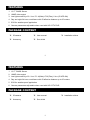
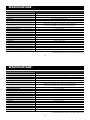
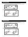
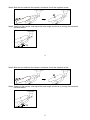
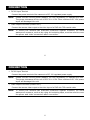
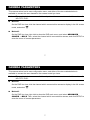
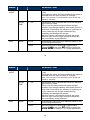
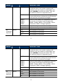
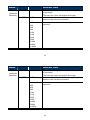
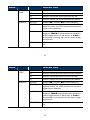
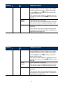
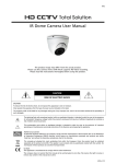
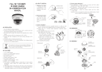
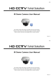
682Z IR Bullet Camera User Manual The product image shown above may differ from the actual product. Please use this camera with a DVR which supports HD video recording. Please read the instructions thoroughly before using the product. d205b_V1.2 682Z IR Bullet Camera User Manual The product image shown above may differ from the actual product. Please use this camera with a DVR which supports HD video recording. Please read the instructions thoroughly before using the product. d205b_V1.2 IMPORTANT SAFEGUARD CAUTION RISK OF ELECTRIC SHOCK CAUTION: To reduce the risk of electric shock, do not expose this apparatus to rain or moisture. Only operate this apparatus from the type of power source indicated on the label. The company shall not be liable for any damages arising out of any improper use, even if we have been advised of the possibility of such damages. The lightning flash with arrowhead symbol, within an equilateral triangle, is intended to alert the user to the presence of uninsulated “dangerous voltage” within the product’s enclosure that may be of sufficient magnitude to constitute a risk of electric shock to persons. This exclamation point within an equilateral triangle is intended to alert the user to the presence of important operating and maintenance (servicing) instructions in the literature accompanying the appliance. All lead-free products offered by the company comply with the requirements of the European law on the Restriction of Hazardous Substances (RoHS) directive, which means our manufacture processes and products are strictly “lead-free” and without the hazardous substances cited in the directive. The crossed-out wheeled bin mark symbolizes that within the European Union the product must be collected separately at the product end-of-life. This applies to your product and any peripherals marked with this symbol. Do not dispose of these products as unsorted municipal waste. Contact your local dealer for procedures for recycling this equipment. CE Mark This apparatus is manufactured to comply with the radio interference. The company does not warrant that this manual will be uninterrupted or error-free. We reserve the right to revise or remove any content in this manual at any time. IMPORTANT SAFEGUARD CAUTION RISK OF ELECTRIC SHOCK CAUTION: To reduce the risk of electric shock, do not expose this apparatus to rain or moisture. Only operate this apparatus from the type of power source indicated on the label. The company shall not be liable for any damages arising out of any improper use, even if we have been advised of the possibility of such damages. The lightning flash with arrowhead symbol, within an equilateral triangle, is intended to alert the user to the presence of uninsulated “dangerous voltage” within the product’s enclosure that may be of sufficient magnitude to constitute a risk of electric shock to persons. This exclamation point within an equilateral triangle is intended to alert the user to the presence of important operating and maintenance (servicing) instructions in the literature accompanying the appliance. All lead-free products offered by the company comply with the requirements of the European law on the Restriction of Hazardous Substances (RoHS) directive, which means our manufacture processes and products are strictly “lead-free” and without the hazardous substances cited in the directive. The crossed-out wheeled bin mark symbolizes that within the European Union the product must be collected separately at the product end-of-life. This applies to your product and any peripherals marked with this symbol. Do not dispose of these products as unsorted municipal waste. Contact your local dealer for procedures for recycling this equipment. CE Mark This apparatus is manufactured to comply with the radio interference. The company does not warrant that this manual will be uninterrupted or error-free. We reserve the right to revise or remove any content in this manual at any time. TABLE OF CONTENTS FEATURES PACKAGE CONTENT DIMENSIONS* SPECIFICATIONS* INSTALLATION CONNECTION CAMERA PARAMETERS 1 1 2 3 4 6 7 TABLE OF CONTENTS FEATURES PACKAGE CONTENT DIMENSIONS* SPECIFICATIONS* INSTALLATION CONNECTION CAMERA PARAMETERS 1 1 2 3 4 6 7 FEATURES 1. 1/2.7” CMOS Sensor 2. 1080P video output 3. Low light sensitivity of 0.1 Lux / F1.4(Wide)~F2.8(Tele), 0 Lux (IR LED ON) 4. Day and night 24-hour surveillance with IR effective distance up to 25 meters 5. IP66 for weather-proof application 6. Camera parameters adjustable when used with HD CCTV DVR PACKAGE CONTENT IR camera User manual Accessory Sun shield Installation sticker 1 FEATURES 1. 1/2.7” CMOS Sensor 2. 1080P video output 3. Low light sensitivity of 0.1 Lux / F1.4(Wide)~F2.8(Tele), 0 Lux (IR LED ON) 4. Day and night 24-hour surveillance with IR effective distance up to 25 meters 5. IP66 for weather-proof application 6. Camera parameters adjustable when used with HD CCTV DVR PACKAGE CONTENT IR camera User manual Accessory Sun shield 1 Installation sticker DIMENSIONS* *Dimensional Tolerance: ± 5mm 2 DIMENSIONS* *Dimensional Tolerance: ± 5mm 2 SPECIFICATIONS* Pick-up Element Number of Pixels Video Frame Rate Min. Illumination S/N Ratio Shutter Speed Lens Lens Angle IR LED IR Effective Distance IR Shift Day & Night Mode IRIS Mode White Balance AGC Sharpness Flickerless BLC IP Rating Operating Temperature Power Source (±10%) Current Consumption (±10%) 1/ 2.7” CMOS image sensor 1930(H) x 1088(V) 1080P@30fps / 1080P@25fps 0.1 Lux / F1.4(Wide)~F2.8(Tele), 0 Lux (IR LED ON) More than 48dB (AGC OFF) 1/30 (1/25) sec ~ 1/720000 (1/600000) sec f2.8 ~ 12mm / F1.4 ~ F2.8 Wide: 104° (Horizontal) / 56° (Vertical) / 124° (Diagonal) Tele: 35° (Horizontal) / 20° (Vertical) / 40° (Diagonal) 36 units Up to 25 meters YES YES AES AUTO / USER / PUSH / 8000K / 6000K / 4200K / 3200K Adjustable Adjustable 50HZ / 60HZ / OFF Adjustable IP66 -25℃ ~ 50℃ DC12V / 0.5A 400mA * The specifications are subject to change without notice. 3 SPECIFICATIONS* Pick-up Element Number of Pixels Video Frame Rate Min. Illumination S/N Ratio Shutter Speed Lens Lens Angle IR LED IR Effective Distance IR Shift Day & Night Mode IRIS Mode White Balance AGC Sharpness Flickerless BLC IP Rating Operating Temperature Power Source (±10%) Current Consumption (±10%) 1/ 2.7” CMOS image sensor 1930(H) x 1088(V) 1080P@30fps / 1080P@25fps 0.1 Lux / F1.4(Wide)~F2.8(Tele), 0 Lux (IR LED ON) More than 48dB (AGC OFF) 1/30 (1/25) sec ~ 1/720000 (1/600000) sec f2.8 ~ 12mm / F1.4 ~ F2.8 Wide: 104° (Horizontal) / 56° (Vertical) / 124° (Diagonal) Tele: 35° (Horizontal) / 20° (Vertical) / 40° (Diagonal) 36 units Up to 25 meters YES YES AES AUTO / USER / PUSH / 8000K / 6000K / 4200K / 3200K Adjustable Adjustable 50HZ / 60HZ / OFF Adjustable IP66 -25℃ ~ 50℃ DC12V / 0.5A 400mA * The specifications are subject to change without notice. 3 INSTALLATION Step1: Loosen the screw as indicated below to move down the camera lens. Then, locate where to install this camera, and fasten the camera to the ceiling or wall. Step2: Adjust the viewing angle of the camera as indicated below. 4 INSTALLATION Step1: Loosen the screw as indicated below to move down the camera lens. Then, locate where to install this camera, and fasten the camera to the ceiling or wall. Step2: Adjust the viewing angle of the camera as indicated below. 4 Step3: Slide the sun shield to the camera, and fasten it with the supplied screw. Step4: Power on the camera, and adjust the focal length and focus by turning the screws as indicated below. 4 Step3: Slide the sun shield to the camera, and fasten it with the supplied screw. Step4: Power on the camera, and adjust the focal length and focus by turning the screws as indicated below. 5 CONNECTION 1. DC12V Input Terminal Connect the power terminal of the camera to a DC 12V regulated power supply. Note: Please use the correct power adaptor, DC12V (regulated), to operate this unit. The power tolerance of this unit is DC12V ± 10%. Over maximum DC 12V power input will damage this unit. 1. Video Output Connector (VIDEO OUT) Connect the camera video output to the video input of a DVR with 75Ω coaxial cable. Note: To ensure the camera has sufficient protection against moisture, an extra waterproof measure, such as by using an insulating tape, must be used to cover the power and video connectors after connection. 6 CONNECTION 1. DC12V Input Terminal Connect the power terminal of the camera to a DC 12V regulated power supply. Note: Please use the correct power adaptor, DC12V (regulated), to operate this unit. The power tolerance of this unit is DC12V ± 10%. Over maximum DC 12V power input will damage this unit. 1. Video Output Connector (VIDEO OUT) Connect the camera video output to the video input of a DVR with 75Ω coaxial cable. Note: To ensure the camera has sufficient protection against moisture, an extra waterproof measure, such as by using an insulating tape, must be used to cover the power and video connectors after connection. 6 CAMERA PARAMETERS This camera series has its own configuration menu, and either of the two methods below is available to access the menu based on the camera model you have. Note: The methods below are available only when the camera is used with our brand’s HD CCTV DVR. Method 1 On the DVR live view, click the channel which connects this camera to display in the full screen mode, and select . Method 2 On the DVR live view, right click to show the DVR main menu, and select ADVANCED CONFIG DCCS. Then, select the channel which connects this camera, and click SETUP to enter the menu of camera parameters. 7 CAMERA PARAMETERS This camera series has its own configuration menu, and either of the two methods below is available to access the menu based on the camera model you have. Note: The methods below are available only when the camera is used with our brand’s HD CCTV DVR. Method 1 On the DVR live view, click the channel which connects this camera to display in the full screen mode, and select . Method 2 On the DVR live view, right click to show the DVR main menu, and select ADVANCED CONFIG DCCS. Then, select the channel which connects this camera, and click SETUP to enter the menu of camera parameters. 7 ADVANCED CONFIG CAMERA DETECTION ALERT NETWORK DISPLAY RECORD DEVICES DCCS NOTIFY CH1 CH2 MENU CH3 F.W. CH4 SETUP 1007 DEVICE XXXXX CONNECTION OK When the camera menu is entered, you’ll see the keys on the bottom right corner to move between and change those configurations. Move between selections. X Quit the camera parameters mode. Change settings. Call the camera parameters menu or enter the currently-selected item. 8 ADVANCED CONFIG CAMERA DETECTION ALERT NETWORK DISPLAY RECORD DEVICES DCCS NOTIFY CH1 CH2 MENU F.W. CH3 CH4 SETUP 1007 DEVICE XXXXX CONNECTION OK When the camera menu is entered, you’ll see the keys on the bottom right corner to move between and change those configurations. Move between selections. X Quit the camera parameters mode. Change settings. Call the camera parameters menu or enter the currently-selected item. 8 MENU DAY / NIGHT DESCRIPTION MODE D TO N EXT Use the external light sensor we added in the camera to detect the surrounding light condition and switch to color or B/W mode. If you’re not satisfying with the mode switch time, you can go to D TO N / N TO D to manually adjust the sensitivity. COLOR Always keep the day and night mode to day mode. B&W Always keep the day and night mode to night mode. AUTO No function. 1 ~ 63 Set the sensitivity for the day & night mode from day to night. The higher the value, the more sensitivity the mode is switched when the light condition is changed. Note: This function is not available when AUTO and COLOR is selected. 9 MENU DAY / NIGHT DESCRIPTION MODE D TO N EXT Use the external light sensor we added in the camera to detect the surrounding light condition and switch to color or B/W mode. If you’re not satisfying with the mode switch time, you can go to D TO N / N TO D to manually adjust the sensitivity. COLOR Always keep the day and night mode to day mode. B&W Always keep the day and night mode to night mode. AUTO No function. 1 ~ 63 Set the sensitivity for the day & night mode from day to night. The higher the value, the more sensitivity the mode is switched when the light condition is changed. Note: This function is not available when AUTO and COLOR is selected. 9 MENU DAY / NIGHT DESCRIPTION N TO D 1 ~ 63 Set the sensitivity for the day & night mode from night to day. The higher the value, the more sensitivity the mode is switched when the light condition is changed. Note: This function is not available when AUTO and COLOR is selected. AWB DELAY TIME 1 ~ 60 MODE AUTO USER Set the delay time in second after which the day and night switch is made. This is used for the environment where the light condition may change suddenly and usually last for a short time, for example, the entrance of a parking lot. It may cause the day & night mode switching constantly and damage the camera. With this function, the camera will delay the mode switch at night since the light change is temporary and unnecessary to pay attention. Automatically adjust the white balance based on the surrounding environment. Manually adjust the white balance parameters. Choose USER, and click (ENTER) to enter the USER MODE to modify R / G / B gain parameters. 10 MENU DAY / NIGHT DESCRIPTION N TO D 1 ~ 63 Set the sensitivity for the day & night mode from night to day. The higher the value, the more sensitivity the mode is switched when the light condition is changed. Note: This function is not available when AUTO and COLOR is selected. AWB DELAY TIME 1 ~ 60 MODE AUTO USER Set the delay time in second after which the day and night switch is made. This is used for the environment where the light condition may change suddenly and usually last for a short time, for example, the entrance of a parking lot. It may cause the day & night mode switching constantly and damage the camera. With this function, the camera will delay the mode switch at night since the light change is temporary and unnecessary to pay attention. Automatically adjust the white balance based on the surrounding environment. Manually adjust the white balance parameters. Choose USER, and click (ENTER) to enter the USER MODE to modify R / G / B gain parameters. 10 MENU AWB DESCRIPTION MODE AE MODE (automatic exposure) (PUSH) It’s used for the environment surrounded largely by a particular color, such as blue, causing color confusion. Aim the camera to a white place, and select (PUSH) to memory this white. Then, aim the camera to where it’s supposed to face. HOLD It’s used to force the camera memorizing the current white balance setting and remain the same even when the environment is changed. 8000K / 6000K / 4200K / 3200K Switch to the suitable color temperature based on the current environment to get the right color. 8000K = Shade; 6000K = Cloud; 4200K = White fluorescent; 3200K = Halogen light bulb. R-G GAIN Adjust the red-green value from 1 ~ 255. B-G GAIN Adjust the blue-green value from 1 ~ 255 ESC Not available for this model. HOLD Not available for this model. DC Not available for this model. 11 MENU AWB DESCRIPTION MODE AE MODE (automatic exposure) (PUSH) It’s used for the environment surrounded largely by a particular color, such as blue, causing color confusion. Aim the camera to a white place, and select (PUSH) to memory this white. Then, aim the camera to where it’s supposed to face. HOLD It’s used to force the camera memorizing the current white balance setting and remain the same even when the environment is changed. 8000K / 6000K / 4200K / 3200K Switch to the suitable color temperature based on the current environment to get the right color. 8000K = Shade; 6000K = Cloud; 4200K = White fluorescent; 3200K = Halogen light bulb. R-G GAIN Adjust the red-green value from 1 ~ 255. B-G GAIN Adjust the blue-green value from 1 ~ 255 ESC Not available for this model. HOLD Not available for this model. DC Not available for this model. 11 MENU DESCRIPTION AE BRIGHT (automatic exposure) SHUTTER 0 ~ 255 Set the level of brightness to adjust the brightness of the image. The more the value, the brighter the image. AUTO Automatically adjust the shutter speed for exposure based on the current environment. 1/25 1/30 1/50 1/60 1/100 1/120 1/250 1/500 1/1000 1/3000 1/10000 Manually choose the shutter speed you need for exposure. 12 MENU DESCRIPTION AE BRIGHT (automatic exposure) SHUTTER 0 ~ 255 Set the level of brightness to adjust the brightness of the image. The more the value, the brighter the image. AUTO Automatically adjust the shutter speed for exposure based on the current environment. 1/25 1/30 1/50 1/60 1/100 1/120 1/250 1/500 1/1000 1/3000 1/10000 Manually choose the shutter speed you need for exposure. 12 MENU DESCRIPTION AE FLICKER (automatic exposure) AGC SPECIAL OFF / 50HZ / 60HZ Enable this function to fix the flicker situation. 1~5 Set the level of Auto Gain Control to detect and enhance the image signals when the light condition is poor. The higher the value, the stronger the signals will be enhanced, and the more noise the image will get. LSC ON / OFF Enable or disable Lens Shading Correction to correct the phenomenon of vignetting when the focal length is short. PRIVACY ZONE AREA SEL. Select AREA1 or AREA2 to show a predefined area for masking. To move and change the area, please go to SX / EX / SY / EY. MASK PAT. Select the color to mask: black / gray / white. Select OFF to disable area masking. 13 MENU DESCRIPTION AE FLICKER (automatic exposure) AGC SPECIAL OFF / 50HZ / 60HZ Enable this function to fix the flicker situation. 1~5 Set the level of Auto Gain Control to detect and enhance the image signals when the light condition is poor. The higher the value, the stronger the signals will be enhanced, and the more noise the image will get. LSC ON / OFF Enable or disable Lens Shading Correction to correct the phenomenon of vignetting when the focal length is short. PRIVACY ZONE AREA SEL. Select AREA1 or AREA2 to show a predefined area for masking. To move and change the area, please go to SX / EX / SY / EY. MASK PAT. Select the color to mask: black / gray / white. Select OFF to disable area masking. 13 MENU SPECIAL DESCRIPTION PRIVACY ZONE MOTION* SX Extend / narrow the current area from the left side. EX Extend / narrow the current area from the right side. SY Extend / narrow the current area from the top. EY Extend / narrow the current area from the bottom. MOTION Enable (ON) / disable (OFF) motion detection. SENSITI. Set the sensitivity to trigger motion detection. The higher the value, the more sensitive the camera to trigger motion detection. ALARM Choose the way to show motion detection is triggered: TRACE to frame the area in red which motion trigger occurs on the screen, or ICON to simply show a running man icon for motion trigger occurrences. HOLD TIME Set how long the alarm lasts in second from 1 to 10. * The function here is for this camera only, and the detection log will be not noted in the DVR. 14 MENU SPECIAL DESCRIPTION PRIVACY ZONE MOTION* SX Extend / narrow the current area from the left side. EX Extend / narrow the current area from the right side. SY Extend / narrow the current area from the top. EY Extend / narrow the current area from the bottom. MOTION Enable (ON) / disable (OFF) motion detection. SENSITI. Set the sensitivity to trigger motion detection. The higher the value, the more sensitive the camera to trigger motion detection. ALARM Choose the way to show motion detection is triggered: TRACE to frame the area in red which motion trigger occurs on the screen, or ICON to simply show a running man icon for motion trigger occurrences. HOLD TIME Set how long the alarm lasts in second from 1 to 10. * The function here is for this camera only, and the detection log will be not noted in the DVR. 14 MENU SPECIAL DESCRIPTION HLC HLC HLC (high light compensation) is used to suppress strong backlight for clearer images. A grey mask will be covered on the source of the strong light. (ENTER) to select the Choose ON and click areas for this function. The screen will be divided into 16 areas. Move to (ENTER) to make the area you want, and click X to O. MASK VALUE Set the darkness of the mask. The more the value, the lighter the grey you’ll get. The less the value, the darker the grey you’ll get. THRESHOLD Set the level of light source which enables masking. The more the value, the stronger the light source will trigger HLC; the less the value, the lighter the light source will trigger HLC. 15 MENU SPECIAL DESCRIPTION HLC HLC HLC (high light compensation) is used to suppress strong backlight for clearer images. A grey mask will be covered on the source of the strong light. (ENTER) to select the Choose ON and click areas for this function. The screen will be divided into 16 areas. Move to (ENTER) to make the area you want, and click X to O. MASK VALUE Set the darkness of the mask. The more the value, the lighter the grey you’ll get. The less the value, the darker the grey you’ll get. THRESHOLD Set the level of light source which enables masking. The more the value, the stronger the light source will trigger HLC; the less the value, the lighter the light source will trigger HLC. 15 MENU EFFECT DESCRIPTION COLOR GAIN 0 ~ 255 Set the level of color saturation. The more the value, the more saturated the color will be, but the more noise the image will get. COLOR HUE 0 ~ 71 Set the level of hue. SHARPNESS 0 ~ 255 Set the level of sharpness to enhance the clarity of image detail by adjusting the aperture and sharpening the edges. The more the value, the sharper the image will be. CONTRAST 0 ~ 255 Set the level of contrast. The more the value, the more the contrast level of the image will be. BRIGHT OFF. -128 ~ 127 Set the level to compensate the brightness of the image if needed. The more the value, the brighter the image will be. 16 MENU EFFECT DESCRIPTION COLOR GAIN 0 ~ 255 Set the level of color saturation. The more the value, the more saturated the color will be, but the more noise the image will get. COLOR HUE 0 ~ 71 Set the level of hue. SHARPNESS 0 ~ 255 Set the level of sharpness to enhance the clarity of image detail by adjusting the aperture and sharpening the edges. The more the value, the sharper the image will be. CONTRAST 0 ~ 255 Set the level of contrast. The more the value, the more the contrast level of the image will be. BRIGHT OFF. -128 ~ 127 Set the level to compensate the brightness of the image if needed. The more the value, the brighter the image will be. 16 MENU EFFECT SYSTEM EXIT DESCRIPTION MIRROR OFF / ON Enable to turn the images horizontally based on your installation situation when necessary. FLIP OFF / ON Enable to flip the image 180° when necessary. CAMERA ID 0 ~ 255 Set the camera ID. ID DISP. OFF / ON Enable or disable the display of the camera ID. NAME DISP. OFF / ON This function has no use. LANGUAGE ENG / 中文 Select the language of the menu: English / Simplified Chinese. FACTORY INIT OFF / ON Enable to restore the camera parameters to factory default values. The camera image will flash once when the reset is done. SAVE & EXIT -- Save all the changes you’ve made in each menu and exit. EXIT -- Exit without saving. 17 MENU EFFECT SYSTEM EXIT DESCRIPTION MIRROR OFF / ON Enable to turn the images horizontally based on your installation situation when necessary. FLIP OFF / ON Enable to flip the image 180° when necessary. CAMERA ID 0 ~ 255 Set the camera ID. ID DISP. OFF / ON Enable or disable the display of the camera ID. NAME DISP. OFF / ON This function has no use. LANGUAGE ENG / 中文 Select the language of the menu: English / Simplified Chinese. FACTORY INIT OFF / ON Enable to restore the camera parameters to factory default values. The camera image will flash once when the reset is done. SAVE & EXIT -- Save all the changes you’ve made in each menu and exit. EXIT -- Exit without saving. 17