1
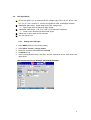
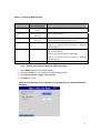
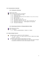
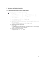
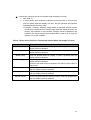
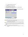
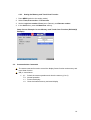
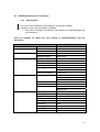
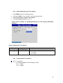
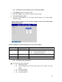
User’s manual
IM DX1K-S2E
Ed-01
Contents
1.
2.
Foreword ....................................................................................................................... 2
LOG Input Specifications ............................................................................................... 3
2.1. Converting the LOG Input (Relationship between the Input Voltage and Digital
Display).................................................................................................................... 3
2.2. LOG Input Mode ......................................................................................................4
2.2.1.
Setting the LOG Input...................................................................................... 4
2.2.2.
Setting the Number of Displayed Mantissa Digits............................................ 5
2.3. Alarm ....................................................................................................................... 6
2.4. Computation Function (Option)................................................................................ 7
2.5. Report Function ....................................................................................................... 7
2.6. Functions That Cannot Be Used.............................................................................. 7
2.7. Number of Grids (Number of Divisions of the Scale Display) .................................. 7
2.8. Communication Output and Binary Data Output Format ......................................... 8
2.9. Communication Output and ASCII Data Output Format .......................................... 8
2.10. Communication Commands .................................................................................... 9
2.10.1.
Setting the LOG Range ............................................................................... 9
2.10.2.
Specifying the Number of Displayed Mantissa Digits................................... 9
2.11. Manual Sample Function ......................................................................................... 9
3. Accuracy and Display Resolution ................................................................................ 10
3.1. Measurement and Display Accuracy (Digital Display)............................................ 10
4. Simulation Function ..................................................................................................... 12
4.1. Display Freeze Function ........................................................................................ 12
4.1.1.
Specifications ................................................................................................ 12
4.1.2.
Event Action Function.................................................................................... 12
4.1.3.
Setting the Display Freeze Function.............................................................. 14
4.1.4.
Operation While the Display is frozen ........................................................... 14
4.2. Memory and Trend Clear Function ........................................................................ 15
4.2.1.
Specifications ................................................................................................ 15
4.2.2.
Event Action Function.................................................................................... 15
4.2.3.
Setting the Memory and Trend Clear Function .............................................. 16
4.3. Communication Commands .................................................................................. 16
4.4. Enabling/Disabling the Time Display ..................................................................... 17
4.4.1.
Specifications ................................................................................................ 17
4.4.2.
Enabling/Disabling the Time Display ............................................................. 18
4.4.3.
Communication Commands .......................................................................... 18
4.5. Special Current Value Mark Function..................................................................... 19
4.5.1.
Specifications ................................................................................................ 19
4.5.2.
Setting the Channel Display of the Current Value Mark ................................ 20
4.5.3.
Communication Commands .......................................................................... 20
1
1. Foreword
Thank you for purchasing the DX1000(N)/DX2000 DXAdvanced.
This user’s manual describes the functions listed below. For a description of other standard
functions, see the DX1000(N) or DX2000 User’s Manual (IM04L41B01-01E or
IM04L42B01-01E) and the Communication Interface User’s Manual (IM04L41B01-17E).
LOG input function
Simulation function
Note)
The Configurator on the accompanying software application DAQSTANDARD for
DXAdvanced does not support the setup items of these TOKUCHU functions.
Note that proper settings will not be applied or the setup file will not be loaded, even if
you attempt to load the setup file created using the DX1000(N) or DX2000 with this
special specifications.
2
2. LOG Input Specifications
2.1.
Converting the LOG Input (Relationship between the Input Voltage and Digital
Display)
Trend display (logarithmic scale): Displays the input voltage on a logarithmic
scale.
Digital display:
Displays the result obtained by converting the
input voltage using the equation below.
¾ The relationship between the input voltage of special LOG range and digital
display value is shown below.
Input voltage
Lower limit of display span
Scale lower limit
VL
1.0E
X
VL
SL
Input X
T
SL
U
Y
Upper limit of display span
Scale upper limit
VU
SU
VU
1.0ESU
Digital display value Y = 10(SU-SL)*(X-VL)/(VU-VL)+SL
3
2.2.
LOG Input Mode
This mode allows you to measure the DC voltage input (DCV: 20 mV, 60 mV, 200
mV, 2 V, 6 V, 20 V, and 50 V), convert to logarithmic scale, and display the data.
Selectable span range: Same range as the DC voltage input
¾ Span Lower must be less than Span Upper.
Selectable scale range: 1.0E-15 to 1.0E+15 (15 decades maximum)
¾ Scale Lower must be less than Scale Upper.
Select two or three digits for the mantissa.
You can set the unit.
2.2.1. Setting the LOG Input
1.
2.
3.
4.
5.
Press MENU (switch to the setting mode).
Select Meas channel > Range, Alarm.
Select the channels in First-CH and Last-CH.
Set Mode to Log.
Set the measurement range, the span, and the exponents of the scale lower and
upper limits.
LOG Input Setup Screen Example (DX1000(N) Example)
4
Table 2-1 Log Input Mode Settings
Setup Item
Selectable Items
Description
(Selectable Range)
Range
Same as the DCV
Sets the range.
range
Span Lower
Varies depending on the
Span Upper
Varies depending on the
Sets the span lower limit.
input type
input type
Scale Lower
1.0E-15 to 1.0E+15
Sets the span upper limit.
* Span Lower must be less than Span Upper.
Sets the scale lower limit.
1.00E-15 to 1.00E+15 when the number of displayed
mantissa digits is 3.
Scale Upper
1.0E-15 to 1.0E+15
Sets the scale upper limit.
* 15 decades maximum.
* Scale Lower must be less than Scale Upper.
1.00E-15 to 1.00E+15 when the number of displayed
mantissa digits is 3.
Unit
Up to 6 characters
Sets the unit (alphanumeric characters).
2.2.2. Setting the Number of Displayed Mantissa Digits
1.
2.
3.
4.
Press MENU (switch to the setting mode).
Hold down FUNC for 3 s to switch to the basic setting mode.
Select Environment > Digits, Time indicate.
Set Digits to 2 or 3.
Setup Screen Example for the Number of Displayed Mantissa Digits (DX1000(N)
Example)
5
2.3.
Alarm
Alarm types in LOG input mode
¾ H, L, T, and t only.
Set the alarm value using a voltage.
Computing method of alarm values
¾ Computing equation of the digital display value
From Y = 10(SU-SL)*(X-VL)/(VU-VL)+SL
logY = (SU-SL)*(X-VL)/(VU-VL)+SL
X = (logY-SL)*(VU-VL)/(SU-SL)+VL
¾ For a computation example, see Table 2-2.
Alarm hysteresis fixed to 0%.
¾ The alarm hysteresis settings specified in the basic setting mode for the
measurement channel are invalid.
Table 2-2 Computation Example of Alarm Values
Span
Lower
Span
Upper
Lower Limit
of Exponent
Upper Limit of
Exponent
1
1
5
5
2
2
8
8
Alarm Value
Equivalent
Voltage
Display
Equivalent
5.0E+6
1.0E+6
4.133
3.667
6
2.4.
Computation Function (Option)
When a channel set to LOG is used in a computation, error data is used as its
measured value.
2.5.
Report Function
Report computation results in error if a channel set to LOG is assigned to a report
channel.
2.6.
Functions That Cannot Be Used
Partial expanded display
¾ Partial expanded display cannot be specified on a channel in LOG input
mode.
Difference computation between channels
¾ There is no limitation on setting a channel in LOG input mode as a reference
channel in a difference computation.
¾ However, if such difference computation is executed, the measured result of
the difference channel is error.
Calibration correction function
¾ Calibration correction cannot be specified on a channel in LOG input mode.
2.7.
Number of Grids (Number of Divisions of the Scale Display)
The number of grids can be set in the range of 4 to 12 or auto (same as the
standard model).
If the number of grids is set to auto on a target channel set to LOG range, the
number of grids is equal to the number of decades. The display shows a LOG grid
in this case.
Channels set to LOG input mode is automatically set to LOG scale.
7
2.8.
Communication Output and Binary Data Output Format
The binary data is an A/D normalized value of the channel set to LOG.
¾ Measured data output (FD command)
¾ FIFO data output (FF command)
(Example)
If the input is 3.000 V measuring in the 6-V range, the binary data
is 10000 (0x2710).
If the measured result is -OVER, the value is set to 0x8001. If the measured result
is +OVER, the value is set to 0x7FFF.
<note> Converting from binary data to LOG value
1. The binary data is output in A/D normalized value. The A/D normalized value is
a scaled value taking the full span value of the range to be 20000. The full span
value of the range is the maximum value that can be set in the range. It is 6 V in
the 6-V range. For example, the A/D normalized values in the 6-V range are as
follows: 6 V = 20000, -6 V = -20000, 1 V = 20000*1/6 = 3333.3.
2. The A/D normalized value is converted to voltage using the following equation.
Voltage = (A/D normalized value)*(full span value of the range)/20000
3. The voltage is converted to a LOG value using the equation given in section 2.1,
“Converting the LOG Input.”
2.9.
Communication Output and ASCII Data Output Format
Measured/computed data
¾ ±DDDDD E±AA
• ±DDDDD: Data mantissa (sign + 5 digits)
• ±AA:
Data exponent (sign + 2 digits)
Value with the number of displayed mantissa digits corrected
with respect to the exponent of the display data.
¾ (Example) When the number of displayed mantissa digits is 3 and the
measured result (display value) is 3.16E*02, the ASCII output is
equal to +00316E+02.
Handling of over data
¾ When the measured result is -OVER: -99999E+99
¾ When the measured result is +OVER: +99999E+99
8
2.10. Communication Commands
2.10.1. Setting the LOG Range
Setting mode setting
SR p1,p2,p3,p4,p5,p6,p7,p8,p9 <terminator>
¾ p1: Channel number (001 to 048)
¾ p2: Setting type (Log)
¾ p3: Measurement range (20 mV, 60 mV, 200 mV, 2 V, 6 V, 20 V, or 50 V)
¾ p4: Span lower limit
¾ p5: Span upper limit p4 < p5
¾ p6: Lower limit of exponent (-15 to 15)
¾ p7: Upper limit of exponent (-15 to 15) p6 < p7 and (p7-p6) ≤ 15
¾ p8: Decimal place (fixed to 0) * Decimal place of the exponent
¾ p9: Unit (up to 6 characters)
2.10.2. Specifying the Number of Displayed Mantissa Digits
Basic setting mode setting
QA p1 <terminator>
¾ p1: Number of displayed digits (2: 2 digits or 3: 3 digits)
2.11. Manual Sample Function
Stored data when a channel set to LOG is assigned
¾ The data is stored in the same format as with the digital value display
(mantissa + exponent).
Events that cause the manual sampled data to be divided
¾ If the number of displayed mantissa digits of the LOG input range is changed,
the data file is divided the next time manual sample is executed.
9
3. Accuracy and Display Resolution
3.1.
Measurement and Display Accuracy (Digital Display)
Computing method of the display value accuracy
¾ Input voltage
X
¾ Lower limit of display span VL
Upper limit of display span
¾ Scale lower limit
SL
Scale upper limit
¾ Digital display value
Y
VU
SU
1) Converting equation for the input voltage (setting)
• Y = 10(SU-SL)*(X-VL)/(VU-VL)+SL
2) Measurement accuracy of input voltage X (uses the negative side due to the
LOG characteristic)
• Xerr =X – (measurement accuracy of the voltage range)
3) Hardware error of the display value
• Y’= Y – Yerr
• The difference from the true value Y is hardware error Y’ when display
value Yerr corresponds to input voltage Xerr.
4) Display accuracy of the mantissa
• Display accuracy = Y’* 1.1 + 1 digit
10
Computing example of the display value accuracy
¾ Integration time 50 Hz
¾ 2 V range
Voltage span
0.0000 to 1.0000 V
¾ LOG span
-2 to 3
1) Determine the converting equation for the setting.
• Y = 10(SU-SL)*(X-VL)/(VU-VL)+SL
= 10(3-(-2))*(X-0)/(1-0)+(-2)
= 10(5X-2)
2) Determine the measurement error with respect to the input voltage.
• Measurement accuracy of the 2 V range = ±(0.05% of rdg + 12 digits)
= ±(0.0005*10000+12)
= ±17 digits
• Therefore, for an input voltage of 1 V, the value will fall within the range
between 0.9983 V and 1.0017 V.
• Since the computation is performed on the negative side with large error in
the LOG characteristics, we obtain Xerr = 0.9983 V.
3) Determine the hardware error of the display value.
• Substitute Xerr, the value determined in 2), into the equation of 1).
Yerr = 10 (5*0.9983-2)
= 9.8 * 102 (truncate values below the one-hundredths place)
• Since the true value is Y = 1.0 * 103, the error is 2 digits.
• Therefore, the hardware error of the display value is given by Y’ = ±2 digits.
4) Display value accuracy of the mantissa
• As a final error, we add the software error to the hardware error.
• Software error = Hardware error * 1.1 + 1 digit
• Display value accuracy = ±(2 digits * 1.1 + 1 digit)
= ±(3.2 digits)
• The fraction is rounded up. When the mantissa is 2 digits, the display
accuracy is ±4 digits.
11
4. Simulation Function
4.1.
Display Freeze Function
4.1.1. Specifications
A function used to stop the updating of the time, trend, digital values, and bar graph.
¾ The display freeze function is controlled through the event action function or
communication commands.
¾ Alarm summary, message summary, and various log displays are also not
updated if they are displayed.
While the display is frozen, display data is also not updated.
Key operation is possible while the display is frozen.
¾ Display operations such as switching the display group are possible.
When recovering from the display freeze condition to normal operation, the trend
display is resumed from where it left off.
¾ Screen image of the operation
“Close” to “Open”
The time display can be enabled or disabled in the basic setting mode.
¾ For details, see section 4.4, “Enabling/Disabling the Time Display.”
4.1.2. Event Action Function
You can freeze or activate the display using the event action function.
¾ The “Display Freeze/Activate” action can be specified only when the event is
set to “Remote.”
The “Display Freeze/Activate” action operates as a level action.
¾ The display freeze action is executed when an open-to-close event (rising
edge) is detected.
¾ The display activate action (normal operation) is executed when a
close-to-open event (falling edge) is detected.
close
open
Normal operation
Display freeze
Normal operation
12
Event action functions that do not operate while the display is frozen
¾ See Table 4-1.
¾ If a level action such as Memory start/stop is executed due to a level event
such as remote while the display is frozen, the DX operation may become
mismatched with the event state.
• Example) If Memory start/stop using remote is specified and the remote
control input is switched from closed to open while the display is frozen, the
memory stop operation is not executed. If display freeze is released in this
condition, the remote control input terminal will be open even though the
memory is in a start condition.
Table 4-1 Event Action Functions That Do Not Operate While the Display Is Frozen
Action
Memory start/stop
Memory start
Memory stop
Event trigger
Save display data
Save event data
Manual sample
Note
Does not operate while the display is frozen. Operates after the
display freeze is released.
Does not operate while the display is frozen. Operates after the
display freeze is released.
Does not operate while the display is frozen. Operates after the
display freeze is released.
Does not operate while the display is frozen. Operates after the
display freeze is released.
However, the action does not operate if the event is set to timer or
match timer.
Does not operate while the display is frozen. Does not operate even
after the display freeze is released.
Does not operate while the display is frozen. Does not operate even
after the display freeze is released.
Does not operate while the display is frozen. Does not operate even
after the display freeze is released.
13
4.1.3. Setting the Display Freeze Function
1.
2.
3.
4.
Press MENU (switch to the setting mode).
Select Timer, Event action > Event action.
Set the Logic box number, Event (set to Remote), and Remote number.
In the Action box, press the Freeze soft key.
Setup Screen Example for the Display Freeze Function (DX1000(N) Example)
4.1.4. Operation While the Display is frozen
If the DX is in a state in which it can switch to the basic setting mode, the DX can
switch to the mode even while the display is frozen.
¾ The display freeze function is released when switching back to the operation
screen from the basic setting mode.
If the power turns OFF and then back ON such as due to a power failure while the
display is frozen (closed state) through remote control, the display freeze function is
released even if there is no change in the remote state (remains at the closed
state).
The automatic display revert function does not operate.
¾ The automatic revert timer is restarted when the display freeze function is
released.
14
4.2.
Memory and Trend Clear Function
4.2.1. Specifications
A function used to clear the internal memory and the trend.
¾ Clears the data area of the internal memory (data files that have been
created are not cleared).
¾ Can be executed while memory sample is in progress.
¾ If you carry out the clear operation on the historical trend display, the display
retains the condition before the operation.
¾ If you execute memory and trend clear on a display other than the operation
display, the screen automatically returns to the operation display.
Methods for clearing the internal memory and trend display
¾ Event action function
¾ Communication command
• For details, see section 4.3, “Communication Commands.”
4.2.2. Event Action Function
You can use the event action function to clear the internal memory and trend
display.
¾ The “Clear the internal memory and trend display” action can be specified
only when the event is set to “Remote.”
The “Clear the internal memory and trend display” action is executed only when an
open-to-close event (rising edge) is detected.
15
4.2.3. Setting the Memory and Trend Clear Function
1.
2.
3.
4.
Press MENU (switch to the setting mode).
Select Timer, Event action > Event action.
Set the Logic box number, Event (set to Remote), and Remote number.
In the Action box, press the MemClear soft key.
Setup Screen Example for the Memory and Trend Clear Function (DX1000(N)
Example)
4.3.
Communication Commands
The same command is used to control the display freeze function and memory and
trend clear function.
QB p1 <terminator>
¾ p1: Switch the screen operation and clear the memory (0 to 2)
• 0: Normal operation
• 1: Freeze the display
• 2: Clear the internal memory and trend display
16
4.4.
Enabling/Disabling the Time Display
4.4.1. Specifications
A function used to disable the time display on the operation display.
Displays on which the time display is disabled
¾ See Table 4-2 Displays on Which the Time Display Is Enabled/Disabled and
the Description.
Table 4-2 Displays on Which the Time Display Is Enabled/Disabled and the
Description
Display Name
Status display
Time display
Trend display
Grid time display
Message display
Circular display
Grid time display
Message display
Historical trend display
Grid time display
Message display
Alarm summary
Message summary
Memory information
Summary display
Cursor time display
Memory summary
Message summary
Alarm summary
Report data display
Log display
Login log
Error log
Communication log
FTP log
WEB log
E-mail log
SNTP log
DHCP log
MODBUS log
Description
Time
Grid time
Written time
Grid time
Written time
Grid time
Written time
Alarm time
Written time
Start time and stop time
Batch comment time
Cursor time
Start/Stop time
Manual sample data time
Report data time
Alarm time
Written time
Start time
Timeout time
Time
Time
Time
Time
Time
Time
Time
Time
Time
17
4.4.2. Enabling/Disabling the Time Display
1.
2.
3.
4.
Press MENU (switch to the setting mode).
Hold down FUNC for 3 s to switch to the basic setting mode.
Select Environment > Digits, Time indicate.
Set Time indicate on/off to On or Off.
Setup Screen Example for Enabling/Disabling the Time Display (DX1000(N)
Example)
Table 4-3 Setting the Time Display
Setup Item
Selectable Items
Description
(Selectable Range)
Time display
On/Off
Enables/disables the time display.
Off: Disable
On: Enable
4.4.3. Communication Commands
QC p1 <terminator>
¾ p1: Enables/disables the time display (On/Off).
• On: Enable
• Off: Disable
18
4.5.
Special Current Value Mark Function
4.5.1. Specifications
A function used to display the channel using two digits for the current value mark
(see Fig. 4-1, “Current Value Mark”) that is displayed in the scale display position
on the trend/historical trend display.
¾ For the channel display, see Table 4-4.
¾ If you set the display to two digits, you will not be able to distinguish between
measurement, computation, and external input channels. In addition, the
external input channels will overlap.
Fig. 4-1 Current Value Mark
Table 4-4 Channel Display of the Current Value Mark
Channel Type
Channel Display of the Current Value Mark
Three Digits (Standard)
Two Digits (Special Setting)
Measurement channel
1 to 48
1 to 48
Computation channel
101 to 160
1 to 60
External input channel
201 to 299
1 to 99
300 to 399
0 to 99
400 to 440
0 to 40
19
4.5.2. Setting the Channel Display of the Current Value Mark
1.
2.
3.
4.
Press MENU (switch to the setting mode).
Hold down FUNC for 3 s to switch to the basic setting mode.
Select Environment > AUX.
Set item 1 under AUX to On (two digits, special setting) or Off (three digits,
standard setting).
Setup Screen Example for the Channel Display of the Current Value Mark
(DX1000(N) Example)
Table 4-5 Setting the Channel Display of the Current Value Mark
AUX Setting
Selectable Items
Description
(Selectable Range)
1
On/Off
Channel display of the current value mark
Off:
Three digits (standard setting)
On:
Two digits (Special setting)
2
On/Off
Not used
3
On/Off
Not used
4
On/Off
Not used
4.5.3. Communication Commands
WU p1,p2,p3,p4,p5 <terminator>
¾ p1: Setup type (AUX)
¾ p2: Channel display of the current value mark (On: two digits, Off: three
digits)
¾ p3: Not used (On/Off)
¾ p4: Not used (On/Off)
¾ p5: Not used (On/Off)
20