1
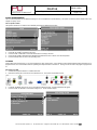
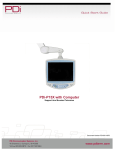
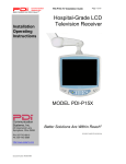
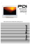
MODEL NUMBER:
Document Number:
PDI-P15X
Better Solutions Are Within Reach®
Support Arm Mounted Television
PD196-134R4
Page 1 of 6
CLEANING AND DISINFECTION
Clean the exterior of this television by removing dust with a lint-free
cloth. CAUTION: To avoid damage to the surface of the television, do
not use abrasive or chemical cleaning agents. Spot test a new
disinfectant by applying test cleaning a non-obvious small spot on the
TV’s back cabinet, keypad, and LCD panel. Allow the disinfectant to
soak per its instructions and then wipe clean. Do not use the
disinfectant if the TV’s surfaces show any sign of discoloration or
softening.
MAINTENANCE AND SERVICING
The TV does not require periodic maintenance other than cleaning.
Never remove the back cover of the TV; this can expose you to high
voltage and other hazards. If the TV does not operate properly, unplug
it and call an authorized service center or PDi.
WARNINGS
CAUTION: To reduce the risk of electric shock, do not remove
cover (or back). No user serviceable parts inside. Refer servicing to
qualified service personnel.
This symbol is intended to alert the user of the
presence of uninsulated ‘dangerous voltage’ within the
product’s enclosure that may be of sufficient magnitude
to constitute a risk of electric shock to persons.
This symbol is intended to alert the user of the
presence of important operating and maintenance
(servicing) instructions in the literature accompanying
the appliance.
OVERHEAD FALLING HAZARD
TV can pose a striking hazard when mounted at an
elevated position. Use only PDi mounting brackets,
support arms, and appropriate hardware to assure TV
will not fall from the mounted position. Failure to do so
may cause injury or death.
RAIN AND MOISTURE
WARNING: To avoid the hazards of fire or electrical
shock, DO NOT expose this television to rain or
moisture.
OXYGEN ENVIRONMENT
WARNING: Do not use in any oxygen tent or oxygen
chamber. Such use may cause a fire hazard.
WET LOCATION
Apparatus shall not be exposed to dripping or
splashing and no objects filled with liquids, such as
vases, shall be placed on the apparatus.
NOTE TO CABLE TV INSTALLER
This reminder is provided to call the cable TV systems installer’s
attention to Article 820-40 of the National Electrical Code. The code
provides guidelines for proper grounding and, in particular, specifies
that the cable ground shall be connected to the grounding system of
the building, as close to the point of the cable entry as practical.
Canadian installations shall be properly grounded in accordance with
the Canadian Electrical Code, Part 1.
FCC
This equipment has been tested and found to comply with the limits for
a Class B digital device, pursuant to part 15 of the FCC Rules. These
limits are designed to provide reasonable protection against harmful
interference when the equipment is operated in a residential or
commercial installation. If this equipment does cause harmful
interference to radio or television reception, which can be determined
by turning the equipment off and on, the user is encouraged to try to
correct the interference by one or more of the following measures:
•
Reorient or relocate the receiving antenna.
•
Increase the separation between the equipment and
receiver.
•
Connect the equipment into an outlet on a circuit different
from that to which the receiver is connected.
•
Consult the dealer or an experienced radio/TV technician for
help.
PRODUCT MODIFICATION
Do not attempt to modify this product in any way without written
authorization. Unauthorized modification could void the user’s
authority to operate this product.
TRADEMARKS
Manufactured under license from Dolby Laboratories. Dolby and the
double-D symbol are trademarks of Dolby Laboratories. All other
brand names and product names used in this manual are trademarks,
registered trademarks, or trade names of their respective holder. PDi
and Better Solutions Are Within Reach are registered trademarks of
PDi Communication Systems, Inc, Springboro, Ohio.
COPYRIGHT
PDi Communication Systems, Inc. claims proprietary right to the
material disclosed in this user manual. This manual is issued for user
information only and may not be used to manufacture anything shown
herein. Copyright 2008 by PDi Communication Systems, Inc. All
rights reserved.
PRODUCT ASSESORIES
(Not Included with TV)
Programming Remote
Patient Remote
Support Arm
Wall Bracket Power Supply
Central Power Supply
Individual Power Supply
PD108-420
PD108-421
PDI-508C-12
PDI-771B, PDI-771CA
PDI-772-HE
PDI-750A
PDi Communication Systems, Inc. 40 Greenwood Lane Springboro, Ohio 45066 USA PH 1-800-628-9870 FX 937-743-5664
MODEL NUMBER:
Document Number:
PDI-P15X
Better Solutions Are Within Reach®
1.
2.
3.
4.
5.
6.
7.
8.
9.
10.
11.
12.
13.
14.
15.
Support Arm Mounted Television
PD196-134R4
Page 2 of 6
IMPORTANT SAFETY INSTRUCTIONS
Read Instructions – All the safety and operating instructions should be
read before the product is operated.
Retain Instructions – The safety and operating instructions should be
retained for future reference.
Heed Warnings – All warnings on the product and in the operating
instructions should be adhered to.
Follow Instructions – All operating and use instructions should be
followed.
Cleaning – Unplug this product from the wall outlet before cleaning. Do
not use liquid cleaners or aerosol cleaners. Use a damp cloth for
cleaning.
Attachments – Do not use attachments not recommended by the product
manufacturer as they may cause hazards.
Water and Moisture – Do not use this product near water – for example,
near a bath tub, wash bowl, kitchen sink, or laundry tub; in a wet
basement; or near a swimming pool, and the like.
Accessories – Do not place this product on an unstable cart, stand,
tripod, bracket, or table. The product may fall, causing serious injury to a
child or adult and serious damage to the product. Use only with a cart,
stand, tripod, bracket, or table recommended by the manufacturer, or sold
with the product. Any mounting of the product should follow the
manufacturer’s instructions, and should use a mounting accessory
recommended by the manufacturer.
A product and cart combination should be
moved with care. Quick stops, excessive force,
and uneven surfaces may cause the product
and cart combination to overturn.
Ventilation – Slots and openings in the cabinet
are provided for ventilation and to ensure
reliable operation of the product and to protect it
from overheating, and these openings must not be blocked or covered.
The openings should never be blocked by placing the product on a bed,
sofa, rug, or other similar survace. This product should not be placed in a
build-in installation such as a bookcase or rack unless proper ventilation
is provided or the manufacturer’s instructions have been adhered to.
Power Sources – This product should be operated only from the type of
power source indicated on the marking label. If you are not sure of the
type of power supply to your home, consult your product dealer or local
power company. For products intended to operate from battery power, or
other sources, refer to the operating instructions.
Grounding or Polarization – This product is equipped with a three-wire
grounding-type plug, a plug having a third (grounding) pin. This plug will
only fit into a grounding-type power outlet. This is a safety feature. If you
are unable to insert the plug into the outlet, contact your electrician to
replace your obsolete outlet. Do not defeat the safety purpose of the
grounding-type plug.
Power-Cord Protection – Power-supply cords should be routed so that
they are not likely to be walked on or pinched by items place upon or
against them, paying particular attention to cords at plugs, convenience
receptacles, and the point where they exit from the product.
Protective Attachment Plug – The product is equipped with an attachment
plug having overload protection. This is a safety feature. See Instruction
Manual for replacement or resetting of protective device. If replacement
of the plug is required, be sure the service technician has used a
replacement plug specified by the manufacturer that has the same
overload protection as the original plug.
Outdoor Antenna Grounding – If an outside antenna or cable system is
connected to the product, be sure the antenna or cable system is
grounded so as to provide some protection against voltage surges and
built-up static charges. Article 810 of the National Electrical Code,
ANSI/NFPA70, provides information with regard to proper grounding of
the mast and supporting structure, grounding of the lead-in wire to an
antenna discharge unit, size of grounding conductors, location of
antenna-discharge unit, connection to grounding electrodes, and
requirements for the grounding electrode. See Figure 1.
16.
17.
18.
19.
20.
21.
22.
23.
24.
25.
Lightning – For added protection for this product during a lightning storm,
or when it is left unattended and unused for long periods of time, unplug it
from the wall outlet and disconnect the antenna or cable system. This will
prevent damage to the product due to lightning and power-line surges.
Power Lines – An outside antenna system should not be located in the
vicinity of overhead power lines or other electric light or power circuits, or
where it can fall into such power lines or circuits. When installing an
outside antenna system, extreme care should be taken to keep from
touching such power lines or circuits as contact with them might be fatal.
Overloading – Do not overload wall outlets, extension cords, or integral
convenience receptacles as they can result in a risk of fire or electric
shock.
Object and Liquid Entry – Never push objects of any kind into this product
through openings as they may touch dangerous voltage points or shortout parts that could result in a fire or electric shock. Never spill liquid of
any kind on the product.
Servicing – Do not attempt to service this product yourself as opening or
removing covers may expose you to dangerous voltage or other hazards.
Refer all servicing to qualified service personnel.
Damage Requiring Service – Unplug this product from the wall outlet and
refer servicing to qualified service personnel under the following
conditions:
a.
When the power-supply cord or plug is damaged,
b.
If liquid has been spilled, or objects have fallen into the
product,
c.
If the product has been exposed to rain or water,
d.
If the product does not operate normally by following the
operating instructions. Adjust only those controls that are
covered by operating instructions as an improper adjustment
of other controls may result in damage and will often require
extensive work by a qualified technician to restore the
product to its normal operation,
e.
If the product has been dropped or damaged in any way, and
f.
When the product exhibits a distinct change in performance –
this indicates a need for service.
Replacement Parts – When replacement parts are required, be sure the
service technician has used replacement parts specified by the
manufacturer or have the same characteristics as the original part.
Unauthorized substitutions may result in fire, electric shock, or other
hazards.
Safety Check – Upon completion of any service or repairs to this product,
ask the service technician to perform safety checks to determine that the
product is in proper operating condition.
Wall or Ceiling Mounting – The product should be mounted to a wall or
ceiling only as recommended by the manufacturer.
Heat – The product should be situated away from heat sources such as
radiators, heat registers, stoves, or other products (including amplifiers)
that produce heat.
Figure 1
PDi Communication Systems, Inc. 40 Greenwood Lane Springboro, Ohio 45066 USA PH 1-800-628-9870 FX 937-743-5664
MODEL NUMBER:
Document Number:
PDI-P15X
Better Solutions Are Within Reach®
Support Arm Mounted Television
PD196-134R4
Page 3 of 6
INSTALLATION ON SUPPORT ARM
The PDI-P15X television is designed to attach to a wall mounted suspension arm capable of supporting a television weighing 12 pounds. The single
coaxial cable on top of the TV is used to supply either low voltage AC or DC power (28VAC or 24VDC) and the RF signal to the television.
DANGER: ARM RECOIL
HAZARD
The safety brake pin must
remain in the SAFETY
BRAKE PIN HOLE whenever
the television is removed
from the arm or when the
arm is removed from the wall
bracket to prevent the arm
from springing open.
Retainer Bolt
Lock Washer
Safety Brake
Pin Hole
1.
Remove and save the Retainer Bolt and
Lock Washer from the TV’s swivel.
2.
Remove the two Nose Cover Retainer
Screws and raise the metal nose cover.
3.
Slide the TV’s swivel completely into the
arm’s clevis (slot) such that the Upper and
Lower Swivel Plates sandwich the arm’s
nose. The nose of the support arm should
rest between each plate.
4.
Align the Retainer Plate’s mounting hole
over the arm mounting hole. Thread the
Retainer Bolt with Lock Washer through
the Top Retainer Plate, the arm’s nose and
then into the Lower Retainer Plate.
Tighten.
5.
7.
Nose Cover
Retainer Screws
The coax cable in the nose of the arm
should be joined with the coax cable from
the television.
Wrench tighten the
connection and cover by sliding the plastic
boot sections into mating position.
IMPORTANT: Finger Only tightening of
this cable connection will result in reliability
problems weeks or months later. Because
the TV draws its power current through this
connection, eventually the finger-tightened
connection will loosen due to thermal
cycling, develop resistance and prompt a
service call. Wrench tighten all “F” fitting
connections!
6.
Safety
Brake Pin
For PDI-500 series arms remove the
Safety Brake Pin from the Safety Brake Pin
Hole, reattach the acorn nut to the pin, and
store the assembly inside the nose of the
arm by attaching it to the coax cable using
the attached plastic clip. For PDI-405
series arms remove the Safety Brake Pin
from the Safety Brake Pin Hole and install
thru rear mounting holes of the nose cover.
Securely tighten. DO NOT store the pin
inside the nose of PDI-405 series arms.
Upper Retainer
Plate
Lower Retainer
Plate
Close the metal nose cover onto the nose.
Reinstall the two Nose Cover Retainer
Screws.
PDi Communication Systems, Inc. 40 Greenwood Lane Springboro, Ohio 45066 USA PH 1-800-628-9870 FX 937-743-5664
MODEL NUMBER:
Document Number:
PDI-P15X
Better Solutions Are Within Reach®
Support Arm Mounted Television
PD196-134R4
Page 4 of 6
PROGRAMMING
NOTE: A programming remote control is required to perform all setup operations for the television. The programming remote (Part Number: PD108420) is NOT packaged with the TV and must be ordered separately. The following instructions assume you have a programming remote, have correctly
mounted the TV, and connected a coax cable that provides both Power and RF signal.
Channel Setup
The TV offers three different programmable channel banks or Service Levels: Free, Basic, and Premium. Only one Service Level is usable at a time.
Four different tuning types are available depending upon the healthcare facilities’ signal style.
Selection of the correct signal type is required for the TV to recognize all possible channels and before any channel programming can begin.
1.
2.
3.
4.
Press the SETUP button to display the SETUP MODE menu.
Press the CH▲ / CH▼ button to select CHANNELS. Press VOL◄ or VOL► to activate the menu item.
In the CHANNELS menu, press the CH▲ / CH▼ button to select Signal.
Press VOL◄ / VOL► to select Air, Cable STD, Cable IRC or Cable HRC. NOTE: Most hospitals use the Cable STD signal style.
Auto Program
The TV automatically scans each available channel for activity. Channels that display activity are memorized into the selected Service Level.
1.
2.
3.
4.
5.
6.
7.
8.
From the CHANNELS menu select Auto Program.
In the AUTO PROGRAM menu, press the CH▲ / CH▼ button to select Mode.
Press VOL◄ / VOL► to set the scope of channel scanning.
Analog Only: TV searches for analog channels only.
Digital Only: TV searches for digital channels only.
Analog and Digital: TV searches for both analog and digital channels.
Press the CH▲ / CH▼ button to select the Channel Sequence menu item.
Press VOL◄ / VOL► to set the Channel Sequence in which the channels are displayed after searching.
Interleave A+D: In the order of channel number regardless of the system.
All A then D: Digital channels are displayed after all analog channels.
Press the CH▲ / CH▼ button to select the Service Level you wish to program. The menu displays the current programming status of each level as
either Programmed or Blank. NOTE: A Programmed service level can also be re-programmed if desired.
Press the VOL► button to start auto programming.
A confirmation menu will appear before proceeding. Press CH▲ to start auto programming. Press CH▼ button to cancel the operation. The TV
will now search all available channels with an on-screen progress percentage displayed. Once complete, press the SETUP button to return to
normal TV viewing. NOTE: Any tuning Mode that includes Digital channels will require several minutes to complete auto programming.
PDi Communication Systems, Inc. 40 Greenwood Lane Springboro, Ohio 45066 USA PH 1-800-628-9870 FX 937-743-5664
MODEL NUMBER:
Document Number:
PDI-P15X
Better Solutions Are Within Reach®
Support Arm Mounted Television
PD196-134R4
Page 5 of 6
SOUND PROGRAMMING
The TV’s internal speakers can be disabled requiring the use of a headphone for private listening. This option is commonly used in dialysis clinics and
multiple occupancy rooms.
Internal Speaker Enable
The speaker’s inside the TV’s cabinet can be Enabled (turned ON) or Disabled (turned OFF).
1.
2.
3.
4.
5.
In the SOUND menu, press CH▲ / CH▼ button to select the Internal Speaker Enable menu item.
Press VOL◄ / VOL► to activate the menu item.
Press the CH▲ / CH▼ button to select the desired Service Level(s) or Sources.
Press VOL◄ / VOL► to alternately select Disabled or Enabled to turn OFF or ON the TV’s internal speakers.
Press the SETUP button to return to the preceding menu.
CLONING
Cloning allows quick programming of a TV from a USB memory stick (Thumb Drive). Clone operation involves first downloading setup information from a
programmed host TV to a Thumb Drive and then uploading the setup information to another TV. Cloning can also be used to re-program a programmed
TV.
Save Settings to USB
1. Create a directory titled “PDITDF” on a USB Thumb Drive.
2. Remove the back access cover from the rear cabinet of the TV. The cover is secured with 3 screws.
3.
4.
Locate the “CLONING” port, turn the TV on, and insert the USB Thumb Drive. A Cloning Main Menu will appear.
Press the CH▲ / CH▼ button to select Save Settings to TV. Press VOL► to display.
PDi Communication Systems, Inc. 40 Greenwood Lane Springboro, Ohio 45066 USA PH 1-800-628-9870 FX 937-743-5664
MODEL NUMBER:
Document Number:
PDI-P15X
Better Solutions Are Within Reach®
5.
6.
7.
Support Arm Mounted Television
PD196-134R4
Page 6 of 6
Select the file name displayed on the second line and rename if desired. Up to 8 characters may be used.
Select Save to download the TV’s setup to the thumb drive. A progress screen will be displayed. A confirmation screen will indicate completion of
the saved file. Press VOL◄ to return to the main Clone menu.
Remove the USB drive to return to normal TV operation. Reattach the TV’s rear access cover with 3 screws.
Restore Setting to TV
1. Remove the back access cover from the rear cabinet of the TV. The cover is secured with 3 screws.
2. Locate the “CLONING” port on the TV’s connector field and insert the USB Thumb Drive. A Cloning Main Menu will appear.
3.
Turn the TV On. Insert the USB Thumb Drive into the “CLONING” port.. A Cloning Main Menu will appear.
4.
Press the CH▲ / CH▼ button to select Restore Settings to TV. Press VOL► to display a list of previously stored TV setups on the USB thumb
drive.
Press the CH▲ / CH▼ button to select a TV’s setup file. Press VOL► once.
A confirmation screen will appear. Press the CH▲ to restore the selected setup file or press VOL► to exit without restoring.
A progress screen will appear as the settings are restored. Once complete, the TV will turn off.
Turn the TV on. Remove the USB thumb drive. Verify correct programming of the TV. Reattach the rear access cover with 3 screws.
5.
6.
7.
8.
Additional Information
Additional information is available in the user manual. Please visit the company web site at pditv.com or contact PDI. Please request document
number: PD196-135.
DISCLAIMER
The author and publisher have used their best efforts in preparing this manual. PDI Communication Systems, Inc. make no representation or warranties
with respect to the accuracy or completeness of the contents of this manual and specifically disclaim any implied warranties or merchantability or fitness for
any particular purpose and shall in no event be liable for any loss of profit or any other damages. The information contained herein is believed accurate, but
is not warranted, and is subject to change without notice or obligation.
PDi Communication Systems, Inc. 40 Greenwood Lane Springboro, Ohio 45066 USA PH 1-800-628-9870 FX 937-743-5664