1
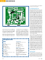
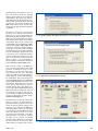
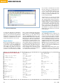
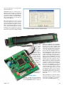
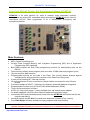
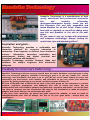
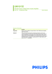
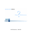
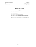
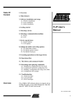
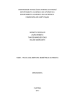
PROJECTS MICROCONTROLLERS USB Flash Board An 8051-based system for rapid software Alexander Kniel Flash microcontrollers are easy to program, which makes them suitable for rapid software development environments and educational uses. In the past, program code was usually downloaded via a serial interface, but nowadays many PCs (especially laptops) only have USB ports. Our versatile Flash Board provides a solution to this problem. It is built around an AT89C5131A, which is an extended 8051-family microcontroller with an 80C52 core and a Full Speed USB port. As a sort of bonus, the IC has a complete update interface for downloading new firmware. Atmel also provides suitable software in the form of its FLIP program, which is available free of charge. The Flash Microcontroller Board originally published in December 2001 is well known to Elektor readers, and it has helped many readers get started in the world of microcontrollers. That’s hardly surprising, since microcontrollers with flash memory, such as the AT89C8252 used in the original Flash Board, are easy to program. As with many other similar boards used for educational purposes, the code is downloaded from a development PC to the microcontroller via a serial interface. Unfortunately, the good old RS232 interface is becoming increasingly rare. Laptops in particular often have only USB ports and no longer come with printer ports or serial ports. If a teacher wants to give his students training boards that they can also program at home using a laptop, a different approach is necessary. The author, an electronics instructor at a vocational/technical school in Heilbronn (Germany), thus developed a version of the Flash Board based on a modern microcontroller with a USB interface. For this purpose he selected the Atmel AT89C5131AM, which has an 80C52 core and thus belongs to the 8051 family, just like the AT89C8252. The IC incorporates an Full Speed USB 22 port, and it is specifically designed for use in USB devices such as printers, cameras, and so on. As a sort of bonus, the microcontroller has a complete update interface for downloading new firmware. This in particular enabled the author, who has a weakness for hardware and all sorts of programming languages, to build an extremely simple USB Flash Board because Atmel also provides suitable software in the form of its FLIP program, which is available free of charge. All you have to do is provide the program code in a hex file and you’re ready to go. Generation-2 Flash Board Many copies of the first version of the new board developed by Alexander Kniel have already been built by students and used with laptop computers. The board design was modified slightly in the Elektor lab, and among other things Elektor designer Chris Vossen added an LCD interface. The board thus follows in the footsteps of the 2001 version of the Elektor Flash Microcontroller Board and is suitable for not only learning how to program microcontrollers, but also for mature applications in device controllers, robots, and many other areas. Everything revolves around the abo- ve-mentioned AT89C5131AM, which is an extended member of the 8051 family. Its core is an 80C52X2 with six clocks per instruction cycle. Besides 32 KB of flash memory, the IC has 1024 bytes of extended RAM, additional EEPROM, and many other useful peripherals. Another helpful feature is that the M version of the microcontroller can also operate at 5 V, and a version in the user-friendly PLCC52 package is available. However, probably the most important feature is the USB 1.1 / USB 2.0 Full Speed module (for the experts: with endpoint 0 for control transfers and six additional endpoints with up to 512 bytes of FIFO memory). If you want to develop USB software, this gives you everything you could wish for, although you do need a bit of technical expertise. Everyone else can regard the microcontroller as a normal 8051 device that can be programmed via USB. The schematic diagram (Figure 1) shows a dual power supply that can draw power either from the USB bus or (with jumper JP4 fitted) via voltage regulator IC2 from an AC adapter connector K9. The D+ and D– pins of the Figure 1. Schematic diagram of the USB Flash Board. elektor - 11/2007 development +5V +5V JP3 1u 16V 22p 1N4001 1 IC2 7805 C12 1000u 16V BAT46 3 C13 C14 100u 16V 100n +5V JP4 D11 6V2 1 C15 C16 100n 100n 9 P0.7 P0.6 D8 P1 C5 100n +5V 10k K8 1 3 5 7 9 2 4 6 8 10 P3.0 P3.2 P3.4 P3.6 +5V 1 P3.1 P3.3 P3.5 P3.7 C6 C7 100n 100n S3 R12 D7 +5V R9 10k S2 D12 D6 P0.5 D5 P0.4 P0.3 8 7 6 5 4 3 2 P0.2 P0.1 P0.0 D4 S4 S5 P3.4 P3.5 P3.6 P3.7 8 7 6 5 1 2 3 4 S6 1k5 D10 2 3 1 2 13 P2.2 11 P2.0 9 7 5 3 1 P3.2 P3.3 P3.0 P3.1 22p D9 K9 D3 K7 P2.3 14 P2.1 12 10 8 P2.4 6 P2.7 4 2 C11 24MHz D2 2 10u 16V X1 D1 3 C10 P0.7 P0.5 P0.3 P0.1 4 C9 P3.0 P3.1 P3.2 P3.3 P3.4 P3.5 P3.6 P3.7 2 4 6 8 10 5 C8 20 29 30 31 32 33 35 39 1 3 5 7 9 6 R10 1k S1 P2.0 P2.1 P2.2 P2.3 P2.4 P2.5 P2.6 P2.7 P0.6 P0.4 P0.2 P0.0 1k5 K3 7 25 JP2 1 2 3 9 10 11 14 15 +5V 8 4k7 R11 P0.0 P0.1 P0.2 P0.3 P0.4 P0.5 P0.6 P0.7 9 UCAP +5V P3.0 P3.1 P3.2 P3.3 P3.4 P3.5 P3.6 P3.7 VSS P1.0 P1.2 P1.4 P1.6 AT89C5131 P1.0 P1.1 P1.2 P1.3 P1.4 P1.5 P1.6 P1.7 RESET PSEN UCAP 52 45 44 42 40 38 37 36 41 2 4 6 8 10 IC1 X2 1 3 5 7 9 P2.0 P2.1 P2.2 P2.3 P2.4 P2.5 P2.6 P2.7 13 P1.1 P1.3 P1.5 P1.7 47 48 49 50 51 4 5 6 43 28 18 P1.0 P1.1 P1.2 P1.3 P1.4 P1.5 P1.6 P1.7 K6 +5V P4.1 P4.0 ALE X1 2n2 8 7 27 AVSS 10n 2 4 6 EA NC NC 19 C3 4k7 4k7 1 3 5 100R C4 26 46 34 R7 K4 P0.0 P0.1 P0.2 P0.3 P0.4 P0.5 P0.6 P0.7 PLLF 12 +5V R1 VDD VREF DD+ 21 R5 100n AVDD 24 22 23 R3 27R R6 100n 17 R2 27R C2 16 R4 1k5 1 2 3 4 6 5 K2 JP1 C1 070125 - 11 11/2007 - elektor 23 PROJECTS MICROCONTROLLERS It can be fitted directly on the PCB or mounted on a front panel. 10 2 9 1 C10 R4 R3 D11 C3 + R2 D9 R10 R12 D10 + C12 ON D12 JP4 10 9 C13 1 2 3 C14 K9 C8 S5 C15 IC1 JP3 JP2 R5 IC2 K8 070125-1 (C) Elektor + C9 C4 2 1 C2 C6 R11 C1 R9 X1 C11 S1 JP1 R6 R7 + R1 C7 P1 S3 C5 6 5 Four full-fledged 8-bit ports S6 K4 2 1 K3 D1 D2 D3 D4 D5 D6 D7 D8 S4 14 13 10 2 9 1 K6 2 1 K7 S2 1 2 3 4 K2 Figure 2. Assembling the circuit board should not present any problems. microcontroller are for the USB data lines. To activate the internal USB boot loader, a low signal level must be applied to PSEN via JP2 (jumper toward the edge of the board). When reset switch S1 is pressed, the boot loader starts up and receives data via the USB port. Jumper posi- Components list Resistors R1 = 1k75 8-way SIL array R2,R3 = 277 R4,R12 = 1k75 R5 = 1007 R6,R7,R11 = 4k77 R9 = 8-way 10k7 array R10 = 1k7 P1 = 10k7 potentiometer Capacitors C10,C11=22pF C3 = 2nF2 C4 = 10nF C1,C2,C5,C6,C7,C14,C15,C16 = 100nF C8 = 10μF 16V C9 = 1μF 16V C12 = 1000μF 16V C13 = 100μF 25V 24 tion JP3 must be closed (jumper toward IC2) to activate the USB port. This connects pullup resistor R4 to the D+ line, which indicates a Full Speed USB device to the PC. If you would like to have a more convenient way to switch between run mode and download mode, you can connect a changeover switch to JP2 and JP3. Semiconductors D1-D8,D12 = LED, red, low-current D9 = BAT46 D10 = 1N4001 D11 = zener diode 6V2 IC1 = AT89C5131AM IC2 = 7805 X1 = 12MHz quartz crystal Miscellaneous JP1,JP4 = 2-way SIL pinheader JP2,JP3 = 3-way SIL pinheader K2 = USB-A socket K3,K6,K8 = 10-way boxheader K4 = 6-way (2x3) pinheader K7 = 14-way boxheader K9 = mains appliance socket, PCB mount S1,S3-S6 = miniature pushbutton PLCC socket PCB, # 070125-1 from Elektor SHOP Kit of parts, # 070125-71 from Elektor SHOP The microcontroller has four fullfledged 8-bit ports, each of which is accessible via a connector and/or assigned a specific peripheral function. Port P0 is available on K3, and it also drives eight LEDs that can be connected to VDD (+5 V) via series resistors. Port P1 is freely usable and accessible via K6. Port P2 is wired to LCD connector K7. An LCD module can be operated in 4-bit mode via this connector, and a contrast adjustment trimpot is provided on the board. Finally, port P3 is specifically intended to be used for inputs, and it can be accessed externally via K8. For testing user-developed programs, the board is fitted with pullup resistors, four pushbutton switches (P3.0…P3.3), and four DIP switches (P3.4…P3.7) on port 3. Switches normally require debouncing, which can usually be implemented in software. The P3.2 and P3.3 lines have supplementary hardware debouncing in the form of capacitors C6 and C7, since these lines are connected to the interrupt inputs of the microcontroller. We also mustn’t forget port P4 with the P4.0 and P4.1 lines, which form the I2C bus interface and are accessible via K4. The bare PCB for the USB Flash Board (Figure 2) is available from the Elektor Shop under order number 0701251. Alternatively, you can purchase a complete kit with all the components under order number 070125-71. Assembling the board is not difficult. Be sure to avoid creating any shorts between D+, D– or the 5 V supply line and ground in the area around the USB socket. As there is no special protection for the D+, D- and 5-V supply lines, it’s a good idea to check this with an ohmmeter – but be sure to remove the microcontroller from its socket first. There is room for an extra 100-nF ceramic capacitor beneath the IC socket, which should be fitted first. It provides optimal supply voltage decoupling. Initial operation You should use an AC adapter (8– 12 V DC) for initial testing. Fit jumper JP4 to select this power source. LED D1 should light up now. If you have already connected an LCD module, it elektor - 11/2007 should display dark pixels in the top line. If necessary, adjust the contrast trimpot until both lines are clearly distinguishable. The upper line will remain dark until the board has been initialised with a program. If you have an oscilloscope, you can also check the 12MHz clock signal on the crystal. This clearly shows that the microcontroller is running. You have to download a program for the first real software test. For this purpose, you can use the Flexible InSystem Programmer (FLIP) software, which you can download free of charge from Atmel’s home page (www.atmel. com). Enter ‘Flip’ as the search term to find FLIP 2.4.6 for Windows (4 MB, Version 2.4.6, updated May 2006). First extract the contents of archive file flip2_4_6.zip to a separate folder and then run the Setup.exe file in that folder. Follow the installation instructions and accept the licence conditions and suggested installation location. You will then see a short list of instructions for what you have to do next (Figure 3). The program is installed by default in C:\Program Files\Atmel\FLIP 2.4.6\. Now connect a cable to the USB connector and fit jumper JP2 in the ‘USB’ position (toward the edge of the board). To be on the safe side, press reset switch S1 and close JP3. This starts the USB download firmware, which waits for contact with the PC to be established. The program reports vendor ID 03EB and product ID 2FFD, which enable Windows to assign a suitable driver. Windows will recognise a new device and ask you to select a suitable driver. Select the driver located in folder C:\Program Files\Atmel\ FLIP 2.4.6\usb (see Figure 4). After it is installed, you will see the new device in the Device Manager window. It can be recognised by its name ‘Jungo AT89C5130/AT89C5131’. If something goes wrong during this process, you have to track down the problem. Possible problem sources include incorrectly fitted jumpers. For instance, if you activate the USB port with JP3 (pullup connected to D+) but do not start the internal firmware (JP2 still in the ‘Run’ position or no reset executed after switching over), Windows will report a new device – but not the right one. By contrast, you might start the update firmware correctly but fit JP3 incorrectly. In this case, Windows will not recognise that a device 11/2007 - elektor Figure 3. The free FLIP programming software displays a list of what you have to do to start using the board. Figure 4. The microcontroller is recognised by Windows as a new device. Figure 5. After you click Run, FLIP downloads the program to the flash memory of the microcontroller. 25 PROJECTS MICROCONTROLLERS If you want to download a new hex file after this test, you must first disconnect the USB cable and then reconnect it – and of course, with the right jumper settings and a Reset first. After this, you must establish the connection again in FLIP. Alternatively, you can leave the USB cable connected and simply open JP3, which will also isolate the device from the USB without interrupting the supply voltage. In order to download a new program, you must first change the setting of JP2 again. The press Reset, wait two seconds, and fit JP3 again. This initialises the USB device. You will have to open the interface in FLIP again, after which you can start the download. Figure 6. Main menu of the BASCOM compiler. is connected, and thus no communication will be established. After a bit of practice, you won’t have any problems making the right settings, and you can establish a communication session with the PC whenever you need it. Program download Now launch FLIP. First you have to use F2, Device à Select, or the IC icon to select the correct IC (AT89C5131). Then use F3, Settings à Communication à USB, or the cable icon to select and open the USB interface. Finally, you have to use F4 or File à Load Hex Hardware test in Bascom-51 ‘Simple test for inputs, ‘outputs and LCD ‘********************** Dim X As Byte P1 = 0 Cls Lcd “ 8051-Test Wait 1 Lowerline Lcd “ Elektor Wait 3 “ “ For X = 1 To 13 Shiftlcd Right Waitms 200 Next Cls Lcd “ Test Port 0 Lowerline Lcd “ Bit 2 exp 0 26 “ “ File to load a suitable hex file. Select program file: 5131_TEST_ELEKTOR. HEX, which you can obtain along with the BASCOM AVR source code from the Elektor home page. Click the Run button (see Figure 5) to download the program code to the flash memory. After this, you must change over JP2 and press the Reset button to run the program. Caution: the BLJB option is enabled automatically with a new microcontroller. You must deselect (uncheck) it the first dime you download a program, since otherwise it will not be possible to run the program after it has been downloaded. P0 = &B11111110 Wait 1 Lowerline Lcd “ Bit 2 exp P0 = &B11111101 Wait 1 Lowerline Lcd “ Bit 2 exp P0 = &B11111011 Wait 1 Lowerline Lcd “ Bit 2 exp P0 = &B11110111 Wait 1 Lowerline Lcd “ Bit 2 exp P0 = &B11101111 Wait 1 Lowerline Lcd “ Bit 2 exp P0 = &B11011111 Wait 1 Lowerline Lcd “ Bit 2 exp P0 = &B10111111 Wait 1 Lowerline 1 2 “ The BASCOM-51 Basic compiler is an ideal tool when you are just getting started with developing programs for the system, although you can also write programs for the microcontroller in C or assembly language. You can download a free demo version of BASCOM-51 from the site of its producer, MCS Electronics (www.mcselec.com). The free version can generate up to 4 KB of code, which is sufficient for many applications. Figure 6 shows the main menu of the compiler. In order to ensure correct operation of the board, you must as- Lcd “ Bit 2 exp 7 P0 = &B01111111 Wait 1 Lowerline Lcd “ All Bits P0 = &B00000000 Wait 1 “ “ “ 3 “ 4 “ 5 “ 6 Programming with BASCOM Cls Lcd “ Test Port 3 “ Lowerline Lcd “ Test Port 0 (LED) Wait 3 Status: P0 = P3 X = P0 Cls Lcd “ Inputs “ Lowerline Lcd “Port 3 = “ ; X ; “ Waitms 60 Goto Status “ “ “ End elektor - 11/2007 sign the LCD pins to port P2 under Options (Figure 7). BASCOM supports configuration of different register files for individual 8051 derivatives. Although there are no specific settings for the AT89C5131, this microcontroller is largely compatible with the 8052, so you should use register file 8052.dat. The listing shows the source code of the test program. It is easy to read and largely self-explanatory. After an introductory message is displayed on the LCD, a running-light routine is executed to check all the LEDs on Port P0. Following this, the inputs on port P3 are read in an endless loop and their states are copied to output port P0 Figure 7. The assignment of the LCD pins to port P2 must be configured under Options. and shown on the LCD. You can actuate the DIP switches (S2) and pushbuttons S3–S6 to check that they are properly assigned to the port pins. The associated output LED will light up for each switch. The test program thus exercises practically all of the hardware. A couple of ideas Finally, a couple of ideas for further projects. The microcontroller has an internal EEPROM, similar to what is 11/2007 - elektor found in the 89S8252 and the 89S8253. However, in this case it is governed by different control registers (SFRs). This means that you cannot escape a careful study of the data sheet if you want to use the supplementary hardware. Like the 8052, the AT89C5131 has another serial interface that can be used with BASCOM by instructions such as Print and Input. However, this requires connecting an additional line driver (such as a MAX232), since the USB Flash Board does not have a serial interface port. This opens the door to typical interface applications, which means that you can use the microcontroller as a PC-based measuring instrument, counter or motor controller. Of course, the AT89C5131 can also do a lot more, including implementing a complete USB device. This is described in several application notes and accompanying source code on the Atmel website. The archive file c5131usb-kbd-stand-alone-1_0_2.zip demonstrates how to construct a USB keyboard. With this USB microcontroller and the extensive software archive, you have essentially everything you need to develop your own USB applications. (070999-1) 27 HandsOn Technology Low Cost 8051C Starter Kit/ Development Board HT-MC-02 HT-MC-02 is an ideal platform for small to medium scale embedded systems development and quick 8051 embedded design prototyping. HT-MC-02 can be used as stand-alone 8051C Flash programmer or as a development, prototyping and educational platform Main Features: 8051 Central Processing Unit. On-chip Flash Program Memory with In-System Programming (ISP) and In Application Programming (IAP) capability. Boot ROM contains low level Flash programming routines for downloading code via the RS232. Flash memory reliably stores program code even after 10,000 erase and program cycles. 10-year minimum data retention. Programmable security for the code in the Flash. The security feature protects against software piracy and prevents the contents of the Flash from being read. 4 level priority interrupt & 7 interrupt sources. 32 general purpose I/O pins connected to 10pins header connectors for easy I/O pins access. Full-duplex enhanced UART – Framing error detection Automatic address recognition. Programmable Counter Array (PCA) & Pulse Width Modulation (PWM). Three 16-bits timer/event counters. AC/DC (9~12V) power supply – easily available from wall socket power adapter. On board stabilized +5Vdc for other external interface circuit power supply. Included 8x LEDs and pushbuttons test board (free with HT-MC-02 while stock last) for fast simple code testing. Industrial popular window Keil C compiler and assembler included (Eval. version). Free Flash Magic Windows software for easy program code down loading. PLEASE READ HT-MC-02 GETTING STARTED MANUAL BEFORE OPERATE THIS BOARD INSTALL ACROBAT READER (AcrobatReader705 Application) TO OPEN AND PRINT ALL DOCUMENTS http://www.handsontec.com HandsOn Technology is a manufacturer of high quality educational and professional electronics kits and modules, uController development/evaluation boards. Inside you will find Electronic Kits and fully assembled and tested Modules for all skill levels. Please check back with us regularly as we will be adding many new kits and products to the site in the near future. Do you want to stay up to date with electronics and computer technology? Always looking for useful hints, tips and interesting offers? Inspiration and goals... HandsOn Technology provides a multimedia and interactive platform for everyone interested in electronics. From beginner to diehard, from student to lecturer... Information, education, inspiration and entertainment. Analog and digital; practical and theoretical; software and hardware... HandsOn Technology provides Designs, ideas and solutions for today's engineers and electronics hobbyists. Creativity for tomorrow's better living... HandsOn Technology believes everyone should have the tools, hardware, and resources to play with cool electronic gadgetry. HandsOn Technology's goal is to get our "hands On" current technology and information and pass it on to you! We set out to make finding the parts and information you need easier, more intuitive, and affordable so you can create your awesome projects. By getting technology in your hands, we think everyone is better off We here at HandsOn like to think that we exist in the same group as our customers >> curious students, engineers, prototypers, and hobbyists who love to create and share. We are snowboarders and rock-climbers, painters and musicians, engineers and writers - but we all have one thing in common...we love electronics! We want to use electronics to make art projects, gadgets, and robots. We live, eat, and breathe this stuff!! If you have more questions, go ahead and poke around the website, or send an email to [email protected]. And as always, feel free to let your geek shine - around here, we encourage it... http://www.handsontec.com