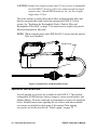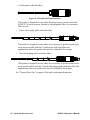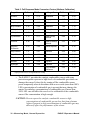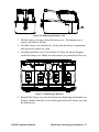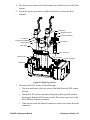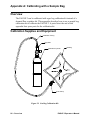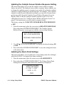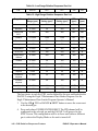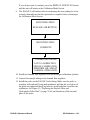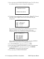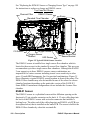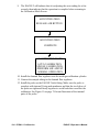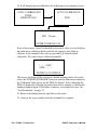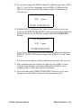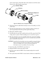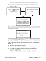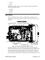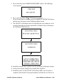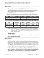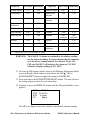
1
EAGLE 2
Operator’s Manual
Part Number: 71-0154RK
Revision: Q
Released: 12/4/13
www.rkiinstruments.com
WARNING
Read and understand this instruction
manual before operating instrument.
Improper use of the gas monitor could
result in bodily harm or death.
Periodic calibration and maintenance of
the gas monitor is essential for proper
operation and correct readings. Please
calibrate and maintain this instrument
regularly! Frequency of calibration
depends upon the type of use you have
and the sensor types. Typical calibration
frequencies for most applications are
between 1 and 3 months, but can be
required more often or less often based
on your usage.
EAGLE 2 Operator’s Manual
Table of Contents
Chapter 1: Introduction . . . . . . . . . . . . . . . . . . . . . . . . . . . . . . . . . . . .1
Overview . . . . . . . . . . . . . . . . . . . . . . . . . . . . . . . . . . . . . . . . . . . . . . . . . . . .
About the EAGLE 2 . . . . . . . . . . . . . . . . . . . . . . . . . . . . . . . . . . . . . . . . . . .
Specifications . . . . . . . . . . . . . . . . . . . . . . . . . . . . . . . . . . . . . . . . . . . . . . . .
About this Manual . . . . . . . . . . . . . . . . . . . . . . . . . . . . . . . . . . . . . . . . . . . . .
1
1
3
4
Chapter 2: Description . . . . . . . . . . . . . . . . . . . . . . . . . . . . . . . . . . . . .6
Overview . . . . . . . . . . . . . . . . . . . . . . . . . . . . . . . . . . . . . . . . . . . . . . . . . . . . 6
Instrument Description . . . . . . . . . . . . . . . . . . . . . . . . . . . . . . . . . . . . . . . . . 6
Case . . . . . . . . . . . . . . . . . . . . . . . . . . . . . . . . . . . . . . . . . . . . . . . . . . 8
Sensors . . . . . . . . . . . . . . . . . . . . . . . . . . . . . . . . . . . . . . . . . . . . . . . . 8
LCD . . . . . . . . . . . . . . . . . . . . . . . . . . . . . . . . . . . . . . . . . . . . . . . . . . . 9
Control Buttons . . . . . . . . . . . . . . . . . . . . . . . . . . . . . . . . . . . . . . . . . 10
Printed Circuit Boards (PCBs) . . . . . . . . . . . . . . . . . . . . . . . . . . . . . 11
Alarm LEDs . . . . . . . . . . . . . . . . . . . . . . . . . . . . . . . . . . . . . . . . . . . 12
Infrared Communications Port . . . . . . . . . . . . . . . . . . . . . . . . . . . . . 12
Buzzer . . . . . . . . . . . . . . . . . . . . . . . . . . . . . . . . . . . . . . . . . . . . . . . . 13
Battery Case & Batteries . . . . . . . . . . . . . . . . . . . . . . . . . . . . . . . . . 13
Flow System . . . . . . . . . . . . . . . . . . . . . . . . . . . . . . . . . . . . . . . . . . . 14
Standard Accessories . . . . . . . . . . . . . . . . . . . . . . . . . . . . . . . . . . . . . . . . . 15
Shoulder Strap . . . . . . . . . . . . . . . . . . . . . . . . . . . . . . . . . . . . . . . . . 15
Hose and Probe . . . . . . . . . . . . . . . . . . . . . . . . . . . . . . . . . . . . . . . . . 15
Optional Accessories . . . . . . . . . . . . . . . . . . . . . . . . . . . . . . . . . . . . . . . . . . 16
Rechargeable Ni-MH Batteries . . . . . . . . . . . . . . . . . . . . . . . . . . . . . 17
Battery Chargers . . . . . . . . . . . . . . . . . . . . . . . . . . . . . . . . . . . . . . . . 17
Optional Probes . . . . . . . . . . . . . . . . . . . . . . . . . . . . . . . . . . . . . . . . 18
External Dilution Fittings . . . . . . . . . . . . . . . . . . . . . . . . . . . . . . . . . 21
Chapter 3: Operation . . . . . . . . . . . . . . . . . . . . . . . . . . . . . . . . . . . . . 22
Overview . . . . . . . . . . . . . . . . . . . . . . . . . . . . . . . . . . . . . . . . . . . . . . . . . . .
Start Up . . . . . . . . . . . . . . . . . . . . . . . . . . . . . . . . . . . . . . . . . . . . . . . . . . . .
Turning On the EAGLE 2 . . . . . . . . . . . . . . . . . . . . . . . . . . . . . . . . .
Performing a Demand Zero . . . . . . . . . . . . . . . . . . . . . . . . . . . . . . .
Turning Off the EAGLE 2 . . . . . . . . . . . . . . . . . . . . . . . . . . . . . . . . .
Using the Battery Charger for Continuous Operation . . . . . . . . . . . . . . . . .
EAGLE 2 Operator’s Manual
22
22
22
27
27
28
Table of Contents
Measuring Mode, Normal Operation . . . . . . . . . . . . . . . . . . . . . . . . . . . . .
Monitoring an Area . . . . . . . . . . . . . . . . . . . . . . . . . . . . . . . . . . . . . .
Using Optional Sample Hoses . . . . . . . . . . . . . . . . . . . . . . . . . . . . .
Using Exhaust Tubing . . . . . . . . . . . . . . . . . . . . . . . . . . . . . . . . . . . .
Combustible Gas Detection . . . . . . . . . . . . . . . . . . . . . . . . . . . . . . .
Monitoring Combustible Gas in the PPM or %Volume Ranges . . . .
Measuring Mode, Alarms . . . . . . . . . . . . . . . . . . . . . . . . . . . . . . . . . . . . . .
Alarm Indications . . . . . . . . . . . . . . . . . . . . . . . . . . . . . . . . . . . . . . .
Resetting and Silencing Alarms . . . . . . . . . . . . . . . . . . . . . . . . . . . .
Responding to Alarms . . . . . . . . . . . . . . . . . . . . . . . . . . . . . . . . . . . .
Display Mode . . . . . . . . . . . . . . . . . . . . . . . . . . . . . . . . . . . . . . . . . . . . . . .
Tips for Using Display Mode . . . . . . . . . . . . . . . . . . . . . . . . . . . . . .
Peak Screen . . . . . . . . . . . . . . . . . . . . . . . . . . . . . . . . . . . . . . . . . . . .
Battery Voltage Screen . . . . . . . . . . . . . . . . . . . . . . . . . . . . . . . . . . .
Gas Display Screen . . . . . . . . . . . . . . . . . . . . . . . . . . . . . . . . . . . . . .
Catalytic (LEL) Sensor Screen. . . . . . . . . . . . . . . . . . . . . . . . . . . . . .
Methane Elimination Mode Screen . . . . . . . . . . . . . . . . . . . . . . . . . .
Relative Response Screen . . . . . . . . . . . . . . . . . . . . . . . . . . . . . . . . .
STEL Screen . . . . . . . . . . . . . . . . . . . . . . . . . . . . . . . . . . . . . . . . . . .
TWA Screen . . . . . . . . . . . . . . . . . . . . . . . . . . . . . . . . . . . . . . . . . . . .
View Alarm Settings Screen . . . . . . . . . . . . . . . . . . . . . . . . . . . . . . .
Select User ID Screen . . . . . . . . . . . . . . . . . . . . . . . . . . . . . . . . . . . .
Select Station ID Screen . . . . . . . . . . . . . . . . . . . . . . . . . . . . . . . . . .
Time in Operation Screen . . . . . . . . . . . . . . . . . . . . . . . . . . . . . . . . .
Date/Time Screen . . . . . . . . . . . . . . . . . . . . . . . . . . . . . . . . . . . . . . .
Data Logging Screen . . . . . . . . . . . . . . . . . . . . . . . . . . . . . . . . . . . .
Data Logging . . . . . . . . . . . . . . . . . . . . . . . . . . . . . . . . . . . . . . . . . . . . . . . .
29
30
30
31
31
33
35
36
37
38
40
40
41
42
42
43
43
43
46
46
46
48
50
51
52
52
53
Chapter 4: Calibration Mode . . . . . . . . . . . . . . . . . . . . . . . . . . . . . . .55
Overview . . . . . . . . . . . . . . . . . . . . . . . . . . . . . . . . . . . . . . . . . . . . . . . . . . .
Calibration Supplies and Equipment . . . . . . . . . . . . . . . . . . . . . . . . . . . . . .
Entering Calibration Mode . . . . . . . . . . . . . . . . . . . . . . . . . . . . . . . . . . . . .
Calibrating Using the Auto Calibration Method . . . . . . . . . . . . . . . . . . . . .
Setting the Fresh Air Reading . . . . . . . . . . . . . . . . . . . . . . . . . . . . . .
Performing a Span Adjustment in Auto Calibration . . . . . . . . . . . . .
Calibrating Using the Single Calibration Method . . . . . . . . . . . . . . . . . . . .
Setting the Fresh Air Reading . . . . . . . . . . . . . . . . . . . . . . . . . . . . . .
Performing a Span Adjustment in Single Calibration . . . . . . . . . . .
Table of Contents
55
56
57
58
58
59
64
64
65
EAGLE 2 Operator’s Manual
Chapter 5: Maintenance . . . . . . . . . . . . . . . . . . . . . . . . . . . . . . . . . . .70
Overview . . . . . . . . . . . . . . . . . . . . . . . . . . . . . . . . . . . . . . . . . . . . . . . . . . .
Troubleshooting . . . . . . . . . . . . . . . . . . . . . . . . . . . . . . . . . . . . . . . . . . . . .
Replacing or Recharging the Batteries . . . . . . . . . . . . . . . . . . . . . . . . . . . .
Replacing the Batteries . . . . . . . . . . . . . . . . . . . . . . . . . . . . . . . . . . .
Recharging the Ni-MH Batteries . . . . . . . . . . . . . . . . . . . . . . . . . . .
Replacing the Hydrophobic Probe’s Particle Filter and Hydrophobic
Filter Disk . . . . . . . . . . . . . . . . . . . . . . . . . . . . . . . . . . . . . . . . . . . . . . . . . .
Replacing the Hydrophobic Filter . . . . . . . . . . . . . . . . . . . . . . . . . . . . . . . .
Replacing the Charcoal Filter . . . . . . . . . . . . . . . . . . . . . . . . . . . . . . . . . . .
Checking the Combustible Gas Sensor’s Condition . . . . . . . . . . . . . . . . . .
Replacing a Sensor . . . . . . . . . . . . . . . . . . . . . . . . . . . . . . . . . . . . . . . . . . .
General Parts List . . . . . . . . . . . . . . . . . . . . . . . . . . . . . . . . . . . . . . . . . . . .
70
70
72
72
74
75
77
79
80
80
84
Appendix A: Calibrating with a Sample Bag . . . . . . . . . . . . . . . . . .86
Overview . . . . . . . . . . . . . . . . . . . . . . . . . . . . . . . . . . . . . . . . . . . . . . . . . . . 86
Calibration Supplies and Equipment . . . . . . . . . . . . . . . . . . . . . . . . . . . . . . 86
Entering Calibration Mode . . . . . . . . . . . . . . . . . . . . . . . . . . . . . . . . . . . . . 87
Calibrating Using the Auto Calibration Method . . . . . . . . . . . . . . . . . . . . . 88
Setting the Fresh Air Reading . . . . . . . . . . . . . . . . . . . . . . . . . . . . . . 88
Performing a Span Adjustment in Auto Calibration . . . . . . . . . . . . . 89
Calibrating Using the Single Calibration Method . . . . . . . . . . . . . . . . . . . . 94
Setting the Fresh Air Reading . . . . . . . . . . . . . . . . . . . . . . . . . . . . . . 94
Performing a Span Adjustment in Single Calibration . . . . . . . . . . . 96
Parts List . . . . . . . . . . . . . . . . . . . . . . . . . . . . . . . . . . . . . . . . . . . . . . . . . . 100
Appendix B: Setup Mode . . . . . . . . . . . . . . . . . . . . . . . . . . . . . . . . .101
Overview . . . . . . . . . . . . . . . . . . . . . . . . . . . . . . . . . . . . . . . . . . . . . . . . . .
Tips for Using Setup Mode . . . . . . . . . . . . . . . . . . . . . . . . . . . . . . . . . . . .
Using Setup Mode . . . . . . . . . . . . . . . . . . . . . . . . . . . . . . . . . . . . . . . . . . .
Setting the Date and Time . . . . . . . . . . . . . . . . . . . . . . . . . . . . . . . .
Setting the Date Format . . . . . . . . . . . . . . . . . . . . . . . . . . . . . . . . .
Setting the Battery Type . . . . . . . . . . . . . . . . . . . . . . . . . . . . . . . . .
Configuring the Channels . . . . . . . . . . . . . . . . . . . . . . . . . . . . . . . .
Configuring the Combustible Gas . . . . . . . . . . . . . . . . . . . . . . . . .
Setting the Catalytic Detection Units . . . . . . . . . . . . . . . . . . . . . . .
Updating the Relative Response Setting . . . . . . . . . . . . . . . . . . . . .
EAGLE 2 Operator’s Manual
101
102
103
104
104
105
105
108
113
114
Table of Contents
Updating the Alarm Point Settings . . . . . . . . . . . . . . . . . . . . . . . . .
Updating the Alarm Latching Setting . . . . . . . . . . . . . . . . . . . . . . .
Updating the Alarm Silence Setting . . . . . . . . . . . . . . . . . . . . . . . .
Turning the User/Station ID Function On or Off . . . . . . . . . . . . . .
Updating the Autocal Values . . . . . . . . . . . . . . . . . . . . . . . . . . . . .
Updating the Backlight Delay Setting . . . . . . . . . . . . . . . . . . . . . .
Updating the Auto Fresh Air Setting . . . . . . . . . . . . . . . . . . . . . . .
Updating the Data Log Interval Setting . . . . . . . . . . . . . . . . . . . . .
Updating the Data Log Overwrite Setting . . . . . . . . . . . . . . . . . . .
Updating the Data Log Memory Setting . . . . . . . . . . . . . . . . . . . . .
Updating the LCD Contrast Setting . . . . . . . . . . . . . . . . . . . . . . . .
Updating the Calibration Reminder Setting . . . . . . . . . . . . . . . . . .
Updating the Calibration Past Due Action Setting . . . . . . . . . . . .
Updating the Calibration Interval . . . . . . . . . . . . . . . . . . . . . . . . .
Updating LC/BH Mode Setting . . . . . . . . . . . . . . . . . . . . . . . . . . . .
Setting the Bar Hole Measurement Time . . . . . . . . . . . . . . . . . . . .
Zero Follower Settings . . . . . . . . . . . . . . . . . . . . . . . . . . . . . . . . . .
Zero Suppression Settings . . . . . . . . . . . . . . . . . . . . . . . . . . . . . . . .
Updating the Confirmation Alert Setting . . . . . . . . . . . . . . . . . . . .
Turning the Password Function On or Off . . . . . . . . . . . . . . . . . . .
Restoring the Default Settings . . . . . . . . . . . . . . . . . . . . . . . . . . . .
Updating the Lunch Break Setting . . . . . . . . . . . . . . . . . . . . . . . . .
Updating the Span Factor Setting . . . . . . . . . . . . . . . . . . . . . . . . . .
Updating the Language Setting . . . . . . . . . . . . . . . . . . . . . . . . . . .
Exiting Setup Mode . . . . . . . . . . . . . . . . . . . . . . . . . . . . . . . . . . . . .
114
116
117
117
118
119
119
120
121
121
122
122
123
123
124
125
125
125
126
126
127
129
129
130
130
Appendix C: Sub PCBs . . . . . . . . . . . . . . . . . . . . . . . . . . . . . . . . . . .132
Overview . . . . . . . . . . . . . . . . . . . . . . . . . . . . . . . . . . . . . . . . . . . . . . . . . .
Description . . . . . . . . . . . . . . . . . . . . . . . . . . . . . . . . . . . . . . . . . . . . . . . . .
Channel Setup and Sub PCBs . . . . . . . . . . . . . . . . . . . . . . . . . . . . . . . . . .
Sub PCBs and CONFIGURE CHANNELS . . . . . . . . . . . . . . . . . . .
Sub PCBs and CONFIGURE GASES . . . . . . . . . . . . . . . . . . . . . . .
132
132
133
133
134
Appendix D: PID Sensors. . . . . . . . . . . . . . . . . . . . . . . . . . . . . . . . . .136
Overview . . . . . . . . . . . . . . . . . . . . . . . . . . . . . . . . . . . . . . . . . . . . . . . . . .
Description . . . . . . . . . . . . . . . . . . . . . . . . . . . . . . . . . . . . . . . . . . . . . . . . .
PID Sensor and Sensor Adapter . . . . . . . . . . . . . . . . . . . . . . . . . . .
PID Sub PCB . . . . . . . . . . . . . . . . . . . . . . . . . . . . . . . . . . . . . . . . . .
Table of Contents
136
136
137
137
EAGLE 2 Operator’s Manual
PID Probe . . . . . . . . . . . . . . . . . . . . . . . . . . . . . . . . . . . . . . . . . . . .
Start Up and Normal Operation . . . . . . . . . . . . . . . . . . . . . . . . . . . . . . . . .
PID Relative Response Feature . . . . . . . . . . . . . . . . . . . . . . . . . . . . . . . . .
PID Sensor Relative Response Screen in Display Mode . . . . . . . . .
PID Calibration . . . . . . . . . . . . . . . . . . . . . . . . . . . . . . . . . . . . . . . . . . . . .
Calibrating with a 4-Gas Cylinder and a PID Cylinder . . . . . . . . .
Calibrating with a 5-Gas Cylinder . . . . . . . . . . . . . . . . . . . . . . . . .
Maintenance . . . . . . . . . . . . . . . . . . . . . . . . . . . . . . . . . . . . . . . . . . . . . . . .
Troubleshooting . . . . . . . . . . . . . . . . . . . . . . . . . . . . . . . . . . . . . . . .
Cleaning the PID Sensor’s Lamp. . . . . . . . . . . . . . . . . . . . . . . . . . .
Replacing PID Sensor’s Lamp . . . . . . . . . . . . . . . . . . . . . . . . . . . . .
Replacing Electrode Stack . . . . . . . . . . . . . . . . . . . . . . . . . . . . . . . .
Replacing the PID Sensor . . . . . . . . . . . . . . . . . . . . . . . . . . . . . . . .
Configuring the PID Gas in Setup Mode . . . . . . . . . . . . . . . . . . . . . . . . . .
Parts List . . . . . . . . . . . . . . . . . . . . . . . . . . . . . . . . . . . . . . . . . . . . . . . . . .
137
138
139
140
143
143
152
160
160
160
165
168
171
172
178
Appendix E: ESM-01 Toxic Sensors . . . . . . . . . . . . . . . . . . . . . . . . .179
Overview . . . . . . . . . . . . . . . . . . . . . . . . . . . . . . . . . . . . . . . . . . . . . . . . . .
Description . . . . . . . . . . . . . . . . . . . . . . . . . . . . . . . . . . . . . . . . . . . . . . . . .
ESM-01 Sensor . . . . . . . . . . . . . . . . . . . . . . . . . . . . . . . . . . . . . . . .
ESM-01 Sub PCB. . . . . . . . . . . . . . . . . . . . . . . . . . . . . . . . . . . . . . .
Start Up and Normal Operation . . . . . . . . . . . . . . . . . . . . . . . . . . . . . . . . .
ESM-01 Calibration . . . . . . . . . . . . . . . . . . . . . . . . . . . . . . . . . . . . . . . . . .
Calibrating with a 4-Gas Cylinder and an ESM-01 Cylinder . . . . .
Calibrating with a 5-Gas Cylinder . . . . . . . . . . . . . . . . . . . . . . . . .
Maintenance . . . . . . . . . . . . . . . . . . . . . . . . . . . . . . . . . . . . . . . . . . . . . . . .
Replacing the ESM-01 Sensor . . . . . . . . . . . . . . . . . . . . . . . . . . . . .
Replacing the H2S Scrubber in the SO2 and HCN Sensors . . . . . . .
Parts List . . . . . . . . . . . . . . . . . . . . . . . . . . . . . . . . . . . . . . . . . . . . . . . . . .
179
179
180
181
181
181
182
191
199
199
200
202
Appendix F: TC Sensors . . . . . . . . . . . . . . . . . . . . . . . . . . . . . . . . . .204
Overview . . . . . . . . . . . . . . . . . . . . . . . . . . . . . . . . . . . . . . . . . . . . . . . . . .
Description . . . . . . . . . . . . . . . . . . . . . . . . . . . . . . . . . . . . . . . . . . . . . . . . .
TC Sensor. . . . . . . . . . . . . . . . . . . . . . . . . . . . . . . . . . . . . . . . . . . . .
TC Sub PCB . . . . . . . . . . . . . . . . . . . . . . . . . . . . . . . . . . . . . . . . . . .
Start Up and Normal Operation . . . . . . . . . . . . . . . . . . . . . . . . . . . . . . . . .
Catalytic (LEL) Sensor Screen . . . . . . . . . . . . . . . . . . . . . . . . . . . . . . . . .
EAGLE 2 Operator’s Manual
204
204
205
205
206
206
Table of Contents
TC Calibration . . . . . . . . . . . . . . . . . . . . . . . . . . . . . . . . . . . . . . . . . . . . . .
Maintenance . . . . . . . . . . . . . . . . . . . . . . . . . . . . . . . . . . . . . . . . . . . . . . . .
Replacing the TC Sensor . . . . . . . . . . . . . . . . . . . . . . . . . . . . . . . . .
Configuring the TC Gas in Setup Mode . . . . . . . . . . . . . . . . . . . . . . . . . .
Parts List . . . . . . . . . . . . . . . . . . . . . . . . . . . . . . . . . . . . . . . . . . . . . . . . . .
207
216
216
217
222
Appendix G: Infrared Carbon Dioxide Sensors . . . . . . . . . . . . . . .223
Overview . . . . . . . . . . . . . . . . . . . . . . . . . . . . . . . . . . . . . . . . . . . . . . . . . .
Description . . . . . . . . . . . . . . . . . . . . . . . . . . . . . . . . . . . . . . . . . . . . . . . . .
Infrared Carbon Dioxide Sensor . . . . . . . . . . . . . . . . . . . . . . . . . . .
Infrared Sub PCB. . . . . . . . . . . . . . . . . . . . . . . . . . . . . . . . . . . . . . .
CO2 Scrubber. . . . . . . . . . . . . . . . . . . . . . . . . . . . . . . . . . . . . . . . . .
Start Up and Normal Operation . . . . . . . . . . . . . . . . . . . . . . . . . . . . . . . . .
Performing a Demand Zero for Carbon Dioxide Sensors . . . . . . . .
Infrared Carbon Dioxide Calibration . . . . . . . . . . . . . . . . . . . . . . . . . . . . .
Maintenance . . . . . . . . . . . . . . . . . . . . . . . . . . . . . . . . . . . . . . . . . . . . . . . .
Replacing the IR CO2 Sensor or Changing Sensor Type. . . . . . . . .
Parts List . . . . . . . . . . . . . . . . . . . . . . . . . . . . . . . . . . . . . . . . . . . . . . . . . .
223
223
224
224
225
226
226
227
236
236
237
Appendix H: Infrared Methane Sensors. . . . . . . . . . . . . . . . . . . . . .238
Overview . . . . . . . . . . . . . . . . . . . . . . . . . . . . . . . . . . . . . . . . . . . . . . . . . .
Target Gases . . . . . . . . . . . . . . . . . . . . . . . . . . . . . . . . . . . . . . . . . .
Description . . . . . . . . . . . . . . . . . . . . . . . . . . . . . . . . . . . . . . . . . . . . . . . . .
Infrared Methane Sensor . . . . . . . . . . . . . . . . . . . . . . . . . . . . . . . . .
Infrared Sub PCB. . . . . . . . . . . . . . . . . . . . . . . . . . . . . . . . . . . . . . .
Start Up and Normal Operation . . . . . . . . . . . . . . . . . . . . . . . . . . . . . . . . .
Detection Ranges . . . . . . . . . . . . . . . . . . . . . . . . . . . . . . . . . . . . . . .
Catalytic (LEL) Sensor Screen . . . . . . . . . . . . . . . . . . . . . . . . . . . . . . . . .
Infrared Methane Calibration. . . . . . . . . . . . . . . . . . . . . . . . . . . . . . . . . . .
Maintenance . . . . . . . . . . . . . . . . . . . . . . . . . . . . . . . . . . . . . . . . . . . . . . . .
Replacing the IR Methane Sensor . . . . . . . . . . . . . . . . . . . . . . . . . .
Parts List . . . . . . . . . . . . . . . . . . . . . . . . . . . . . . . . . . . . . . . . . . . . . . . . . .
238
238
239
240
240
240
240
240
241
250
250
251
Appendix I: Infrared Hydrocarbon Sensor . . . . . . . . . . . . . . . . . . .252
Overview . . . . . . . . . . . . . . . . . . . . . . . . . . . . . . . . . . . . . . . . . . . . . . . . . . 252
Target Gases . . . . . . . . . . . . . . . . . . . . . . . . . . . . . . . . . . . . . . . . . . 252
Description . . . . . . . . . . . . . . . . . . . . . . . . . . . . . . . . . . . . . . . . . . . . . . . . . 252
Table of Contents
EAGLE 2 Operator’s Manual
Infrared Hydrocarbon Sensor . . . . . . . . . . . . . . . . . . . . . . . . . . . . .
Infrared Sub PCB. . . . . . . . . . . . . . . . . . . . . . . . . . . . . . . . . . . . . . .
Start Up and Normal Operation . . . . . . . . . . . . . . . . . . . . . . . . . . . . . . . . .
0-100 %LEL/2.0-30.0 %vol Autoranging . . . . . . . . . . . . . . . . . . . .
Catalytic (LEL) Sensor Screen . . . . . . . . . . . . . . . . . . . . . . . . . . . . . . . . .
Infrared Hydrocarbon Calibration . . . . . . . . . . . . . . . . . . . . . . . . . . . . . . .
Maintenance . . . . . . . . . . . . . . . . . . . . . . . . . . . . . . . . . . . . . . . . . . . . . . . .
Replacing the IR Hydrocarbon Sensor . . . . . . . . . . . . . . . . . . . . . .
Parts List . . . . . . . . . . . . . . . . . . . . . . . . . . . . . . . . . . . . . . . . . . . . . . . . . .
253
253
254
254
254
255
264
264
265
Appendix J: Methane Elimination Mode . . . . . . . . . . . . . . . . . . . . .266
Overview . . . . . . . . . . . . . . . . . . . . . . . . . . . . . . . . . . . . . . . . . . . . . . . . . . 266
Monitoring in Methane Elimination Mode . . . . . . . . . . . . . . . . . . . . . . . . 266
Calibration . . . . . . . . . . . . . . . . . . . . . . . . . . . . . . . . . . . . . . . . . . . . . . . . . 269
Appendix K: Using the EAGLE 2 in Bar Hole Mode . . . . . . . . . . .270
Overview . . . . . . . . . . . . . . . . . . . . . . . . . . . . . . . . . . . . . . . . . . . . . . . . . .
Start Up, Bar Hole Mode . . . . . . . . . . . . . . . . . . . . . . . . . . . . . . . . . . . . . .
Turning on EAGLE 2, Bar Hole Mode . . . . . . . . . . . . . . . . . . . . . .
Performing a Demand Zero, Bar Hole Mode . . . . . . . . . . . . . . . . .
Bar Hole Testing . . . . . . . . . . . . . . . . . . . . . . . . . . . . . . . . . . . . . . . . . . . .
Performing a Bar Hole Test. . . . . . . . . . . . . . . . . . . . . . . . . . . . . . .
Turning off the EAGLE 2, Bar Hole Mode . . . . . . . . . . . . . . . . . . .
270
270
270
275
276
276
278
Appendix L: Using the EAGLE 2 in Leak Check Mode . . . . . . . . .279
Overview . . . . . . . . . . . . . . . . . . . . . . . . . . . . . . . . . . . . . . . . . . . . . . . . . .
Start Up, Leak Check Mode. . . . . . . . . . . . . . . . . . . . . . . . . . . . . . . . . . . .
Turning On the EAGLE 2, Leak Check Mode . . . . . . . . . . . . . . . . .
Performing a Demand Zero, Leak Check Mode . . . . . . . . . . . . . . .
Leak Testing . . . . . . . . . . . . . . . . . . . . . . . . . . . . . . . . . . . . . . . . . . . . . . . .
Locating a Leak . . . . . . . . . . . . . . . . . . . . . . . . . . . . . . . . . . . . . . . .
Turning the Buzzer On and Off In Leak Check Mode . . . . . . . . . . .
Turning Off the EAGLE 2, Leak Check Mode . . . . . . . . . . . . . . . . .
279
279
279
284
284
285
285
286
Appendix M: EAGLE 2 Tank Tester Model. . . . . . . . . . . . . . . . . . .287
Description . . . . . . . . . . . . . . . . . . . . . . . . . . . . . . . . . . . . . . . . . . . . . . . . . 287
Float Probe Assembly . . . . . . . . . . . . . . . . . . . . . . . . . . . . . . . . . . . 288
Dilution Fitting (1:1) . . . . . . . . . . . . . . . . . . . . . . . . . . . . . . . . . . . . 288
EAGLE 2 Operator’s Manual
Table of Contents
Start Up . . . . . . . . . . . . . . . . . . . . . . . . . . . . . . . . . . . . . . . . . . . . . . . . . . .
Alarms . . . . . . . . . . . . . . . . . . . . . . . . . . . . . . . . . . . . . . . . . . . . . . . . . . . .
Calibration . . . . . . . . . . . . . . . . . . . . . . . . . . . . . . . . . . . . . . . . . . . . . . . . .
Parts List . . . . . . . . . . . . . . . . . . . . . . . . . . . . . . . . . . . . . . . . . . . . . . . . . .
289
291
291
292
Appendix N: Using the EAGLE 2 in Inert Mode. . . . . . . . . . . . . . 293
Description . . . . . . . . . . . . . . . . . . . . . . . . . . . . . . . . . . . . . . . . . . . . . . . . .
Alarms . . . . . . . . . . . . . . . . . . . . . . . . . . . . . . . . . . . . . . . . . . . . . . . . . . . .
Start Up . . . . . . . . . . . . . . . . . . . . . . . . . . . . . . . . . . . . . . . . . . . . . . . . . . .
Operation . . . . . . . . . . . . . . . . . . . . . . . . . . . . . . . . . . . . . . . . . . . . . . . . . .
293
293
296
298
WARNING: Understand manual before operating. Substitution of
components may impair intrinsic safety. To prevent ignition
of a hazardous atmosphere, batteries must only be changed
or charged in an area known to be nonhazardous. Not tested
in oxygen enriched atmospheres (above 21%).
NOTE: RKI Instruments, Inc. recommends that you refer to ISA-RP12.13,
Part II-1987 or an equivalent international recommended practice
for guidance in the use of combustible gas detection instruments.
Table of Contents
EAGLE 2 Operator’s Manual
Chapter 1: Introduction
Overview
This chapter briefly describes the EAGLE 2 gas monitor. This chapter also
describes the EAGLE 2 Operator’s Manual (this document). Table 1 at the
end of this chapter lists the specifications for the EAGLE 2.
About the EAGLE 2
Using an advanced detection system consisting of up to six gas sensors, the
EAGLE 2 sample draw gas monitor is capable of detecting the presence of
combustible gas, oxygen (O2), carbon monoxide (CO), hydrogen sulfide
(H2S), and various other toxic gases simultaneously. The EAGLE 2’s rugged,
reliable, and easy-to-use design makes it ideally suited for a wide range of
applications, including sewage treatment plants, utility manholes, tunnels,
hazardous waste sites, power stations, petrochemical refineries, mines, paper
mills, drilling rigs, and fire fighting stations. The EAGLE 2 offers a full
range of features including:
• Simultaneous monitoring of one to six gases. The standard configuration
includes four sensors for combustible gas (%LEL, ppm, and %volume),
oxygen, carbon monoxide (CO), and hydrogen sulfide (H2S).
• Choice of three operating modes:
•
Normal Mode for typical confined space or area monitoring. Normal
Mode is the standard factory setting.
•
Bar Hole Mode for checking of bar holes when searching for
underground gas leaks
•
Leak Check Mode for locating leaks in valves and piping
• Sample-drawing pump with up to 125 foot range
• Liquid crystal display (LCD) for complete and understandable
information at a glance
• Ultrabright alarm LEDs
• Distinctive audible alarm for dangerous gas conditions or unit
malfunction
• Microprocessor control for reliability, ease of use, and advanced
capabilities
EAGLE 2 Operator’s Manual
Overview • 1
• Data logging functions (when used in Normal Mode)
• Alarm trend data (when used in Normal Mode)
• STEL and TWA (when used in Normal Mode) and over range alarms
• Peak readings (when used in Normal Mode)
• Built-in time function
• Lunch break feature
• RF shielded high impact plastic case
• CSA classified for Class I, Division I, Groups A, B, C, and D hazardous
atmospheres
WARNING: The Model EAGLE 2 detects oxygen deficiency, elevated
levels of oxygen, combustible gases, carbon monoxide, and
hydrogen sulfide, all of which can be dangerous or life
threatening. When using the EAGLE 2, you must follow the
instructions and warnings in this manual to assure proper
and safe operation of the unit and to minimize the risk of
personal injury. Be sure to maintain and periodically
calibrate the EAGLE 2 as described in this manual.
NOTE: ONLY THE COMBUSTIBLE GAS DETECTION PORTION OF
THIS INSTRUMENT HAS BEEN ASSESSED FOR
PERFORMANCE.
2 • About the EAGLE 2
EAGLE 2 Operator’s Manual
Specifications
Table 1: Standard Sensor Specifications
Combustible Gas,
Methane (CH4)
Calibration Standard
Oxygen (O2)
Hydrogen
Sulfide (H2S)
Carbon
Monoxide (CO)
Detection
Range
0 - 100 %LEL
0 - 40 volume%
0 - 100.0 ppm
0 - 500 ppm
Reading
Increment
1 %LEL
0.1 volume %
0.5 ppm
1 ppm
Alarm 1
Factory Setting
10 %LEL*
19.5 volume %*
10.0 ppm*
25 ppm*
Alarm 2
Factory Setting
50 %LEL
23.5 volume %
30.0 ppm
50 ppm
STEL Alarm
n/a
n/a
15.0 ppm
200 ppm
TWA Alarm
n/a
n/a
10.0 ppm
25 ppm
* When calibrating the EAGLE 2 with the Auto Calibration or the Single Calibration method, the calibration gas
value must be equal to or higher than the alarm 1 setting. See “Updating the Alarm Point Settings” on page 114
for instructions to change the alarm points if necessary for the desired calibration gas value.
Table 2: EAGLE 2 Specifications
Sampling
Method
Sample Draw
Response
Time
T90 Within 30 Seconds
Display
Graphics LCD Display
Operating
Temperature
& Humidity
-20°C to 50°C/Below 85% RH (Without Condensation)
Indication
Accuracy
Combustible Gas (LEL), Catalytic Type Sensor
• -10°C to 40°C: 5% of full scale
• -20°C to 50°C: 6% of full scale
Combustible Gas (ppm), Catalytic Type Sensor
• ± 25 ppm or ± 5% of reading (whichever is greater)
Oxygen
• ± 0.5% O2
Hydrogen Sulfide
• ± 5% of reading or ± 2 ppm H2S (whichever is greater)
Carbon Monoxide
• ± 5% of reading or ± 5 ppm CO (whichever is greater)
EAGLE 2 Operator’s Manual
Specifications • 3
Safety/
Regulatory
186718
CSA classified as Intrinsically Safe. Exia. Class I, Groups A, B, C, & D.
Temperature Code T3C.
Power
Supply
Continuous
Operating
Hours
@ 25 °C
Case
• Four C size alkaline batteries, standard
• Four C size Ni-MH batteries, optional
• Alkaline Batteries: 16 Hours (Non Alarm Operation, Fully Charged)
• Ni-MH Batteries: 18 Hours (Non Alarm Operation, Fully Charged)
High-impact Plastic, RF Shielded, Dust and Weather Proof
Standard
Accessories
• 5 foot hose
• Hydrophobic probe
• Shoulder Strap
Optional
Accessories
•
•
•
•
•
•
•
•
•
Dimensions
and Weight
Rechargeable NiMH Batteries
115 VAC Charger
12 VDC Charger
Hoses of Various Lengths, See “General Parts List” on page 84.
Dilution Fitting (1:1 and 3:1)
Various Probes, See “General Parts List” on page 84
Data Logger Management Program (Windows® 2000, XP, and Vista)
Maintenance Data Loader Program (Windows® 2000, XP, and Vista)
IrDA/USB Cable for connecting to a computer when using the Data Logger
Management Program and Maintenance Data Loader Program (not
needed if computer has an infrared port)
Approximately 171(H) x 65(W) x 39(D) mm (5.6”H x 2.5”W x 1.5”D)
Approximately 310 g (11 oz.)
About this Manual
The EAGLE 2 Operator’s Manual uses the following conventions for notes,
cautions, and warnings.
NOTE: Describes additional or critical information.
CAUTION: Describes potential damage to equipment.
WARNING: Describes potential danger that can result in injury or death.
The EAGLE 2 Operator’s Manual is organized as follows:
• Chapter 1 is an introduction to the EAGLE 2.
• Chapter 2 describes the components of the EAGLE 2.
4 • About this Manual
EAGLE 2 Operator’s Manual
• Chapter 3 describes the operation of the EAGLE 2.
• Chapter 4 describes Calibration Mode which allows you to calibrate the
EAGLE 2’s active channels.
• Chapter 5 describes the EAGLE 2’s maintenance requirements and
procedures.
• Appendix A describes calibration of the EAGLE 2 using a sample bag.
• Appendix B describes Setup Mode which allows you to configure
different parameters of the EAGLE 2.
• Appendix C describes the sub PCBs that are installed for optional sensors
and how they affect gas and channel configuration.
• Appendix D describes the PID sensors and the operation of the EAGLE 2
with a PID sensor installed.
• Appendix E describes the ESM-01 sensors and the operation of the
EAGLE 2 with an ESM-01 sensor installed.
• Appendix F describes the TC sensors and the operation of the EAGLE 2
with a TC sensor installed.
• Appendix G describes the infrared CO2 sensors and the operation of the
EAGLE 2 with an infrared CO2 sensor installed.
• Appendix H describes the infrared methane sensors and the operation of
the EAGLE 2 with an infrared methane sensor installed.
• Appendix I describes the infrared hydrocarbon sensor and the operation
of the EAGLE 2 with an infrared hydrocarbon sensor installed.
• Appendix J describes the operation of the EAGLE 2 in Methane
Elimination Mode.
• Appendix K describes the operation of the EAGLE 2 in Bar Hole Mode.
• Appendix L describes the operation of the EAGLE 2 in Leak Check
Mode.
• Appendix M describes the Tank Tester Model of the EAGLE 2.
• Appendix N describes the operation of the EAGLE 2 in Inert Mode
EAGLE 2 Operator’s Manual
About this Manual • 5
Chapter 2: Description
Overview
This chapter describes the EAGLE 2 instrument and accessories.
Instrument Description
The EAGLE 2 includes the case, sensors, LCD, control buttons, printed
circuit boards, alarm LEDs, infrared communication port, buzzer, battery
case and batteries, and flow system.
Alarm LEDs
Inlet Fitting
LCD Display
Control Buttons
PO WER
ENTE R
RES ET
DISP LAY
ADJUST
NO
AIR
RANGE
YE S
SHIFT
Figure 1: Component Location, Top View
6 • Overview
EAGLE 2 Operator’s Manual
Top Case
Handle
Strap
Case Screw, 3X
(Hidden From view)
Bottom Case
Case Foot, 6X
Figure 2: Component Location, Side View
Buzzer
Inlet Fitting
Exhaust Fitting
Charging Jack
Battery Case
Thumbscrew
Infrared Port
Figure 3: Component Location, Front & Back
EAGLE 2 Operator’s Manual
Instrument Description • 7
Case
The EAGLE 2’s sturdy, high-impact plastic case is radio frequency (RF)
resistant and is suitable for use in many environmental conditions, indoors
and out. The case is dust proof and water resistant. It’s two main components,
the top case and bottom case, are held together with three screws located on
the bottom case. The interface between the top case and bottom case is
gasketed. A sturdy, well balanced handle on the top case allows you to hold
the instrument comfortably. A clear plastic window is located on the top case
to the front of the handle for viewing the LCD.
A removable battery case is located at the rear of the bottom case. A
thumbscrew secures the battery case to the bottom case. The interface
between the battery case and the bottom case is gasketed. Six raised feet on
the bottom of the case, four on the bottom case and two on the battery
compartment, raise the EAGLE 2 slightly from the surface on which it rests.
Sensors
The EAGLE 2 uses up to six sensors to monitor combustible gas, oxygen
(O2), carbon monoxide (CO), hydrogen sulfide (H2S), and various other toxic
gases simultaneously. The sensors are located inside the EAGLE 2 bottom
case and are installed in the flow chamber. The sensors described below are
the four standard sensors. See “Appendix D: PID Sensors” for a description
of the PID sensors, “Appendix E: ESM-01 Toxic Sensors” for a description
of the ESM-01 toxic sensors, “Appendix F: TC Sensors” for a description of
the TC sensors, “Appendix G: Infrared Carbon Dioxide Sensors” for a
description of the IR CO2 sensors, “Appendix H: Infrared Methane Sensor”
for a description of the IR methane sensors, and “Appendix I: Infrared
Hydrocarbon Sensor” for a description of the IR hydrocarbon sensor. The
standard sensors use different detection principles as described below.
Catalytic Combustible Gas Sensor (LEL Sensor)
The catalytic combustible gas (LEL) sensor detects combustible gas in the
%LEL range. It uses a catalytic element for detection. The reaction of gas
with oxygen on the catalyst causes a change in the resistance of the element
which changes the current flowing through it. The current is amplified by the
EAGLE 2’s circuitry, converted to a measurement of combustible gas
concentration, and displayed on the LCD.
The LEL sensor housing includes a sintered metal flame arrestor on one end
that allows gas to diffuse into the sensor. On the other end, five pins extend
from the sensor. The sensor cable connects to these pins on one end and
terminates in a four-position connector on the other end which plugs into the
HC socket on the main PCB (see “Main PCB” on page 12).
8 • Instrument Description
EAGLE 2 Operator’s Manual
Oxygen Sensor
The O2 sensor is a galvanic type of sensor. A membrane behind the openings
on the sensor face allows gas to diffuse into the sensor at a rate proportional
to the partial pressure of oxygen. The oxygen reacts in the sensor and
produces a voltage proportional to the concentration of oxygen. The voltage
is measured by the EAGLE 2’s circuitry, converted to a measurement of gas
concentration, and displayed on the LCD.
The sensor includes a short cable that terminates in a round 7-position
connector. It mates with the OXY pins on the main PCB (see “Main PCB” on
page 12).
CO and H2S Sensors
The CO and H2S sensors are electrochemical sensors that consist of three
precious metal electrodes in a dilute acid electrolyte. A gas permeable
membrane covers the sensor face and allows gas to diffuse into the
electrolyte. The gas reacts in the sensor and produces a current proportional
to the concentration of the target gas. The current is amplified by the EAGLE
2’s circuitry, converted to a measurement of gas concentration, and displayed
on the LCD.
The CO and H2S sensors are physically very similar. Except for their
markings and wire colors, they look almost identical. A three-position
connector at the end of a 2-wire cable from each sensor plugs into a socket on
the main PCB. The sockets on the main PCB for the CO and H2S sensors are
labeled CO and H2S. Normally, the CO connector plugs into the CO socket
and the H2S plugs into the H2S socket. However, because of the way that the
main PCB circuitry is arranged, if the CO sensor is plugged into the H2S
socket and the H2S sensor is plugged into the CO socket, the sensors will still
operate properly and the CO and H2S readings will still appear on the
channels that are programmed for those gases.
LCD
A digital LCD (liquid crystal display) is visible through a clear plastic
window in the top case. The LCD simultaneously shows the gas reading for
all installed sensors. The LCD also shows information for each of the
EAGLE 2’s operating modes.
EAGLE 2 Operator’s Manual
Instrument Description • 9
Control Buttons
Four control buttons are located below the LCD. They are, from left to right,
POWER ENTER RESET, DISPLAY ADJUST NO, AIR ▲ YES, and
RANGE ▼ SHIFT.
Table 3: EAGLE 2 Control Button Functions
Button
Function(s)
POWER ENTER
RESET
• turns the EAGLE 2 on and off
• silences and resets audible alarm if Alarm Latching is set to
Latching and Alarm Silence is set to ON
• enters instructions, values, and settings into the EAGLE 2’s
microprocessor
DISPLAY ADJUST
NO
• activates Display Mode
• silences and resets audible alarm if Alarm Latching is set to
Latching and Alarm Silence is set to ON
• enters instructions into the EAGLE 2’s microprocessor
AIR ▲ YES
• activates the demand zero function (adjusts the EAGLE 2’s
fresh air reading)
• silences and resets audible alarm if Alarm Latching is set to
Latching and Alarm Silence is set to ON
• enters instructions into the EAGLE 2’s microprocessor
• moves the cursor on the LCD up the screen
• increases the value of a parameter available for adjustment
• scrolls through parameter options
RANGE ▼ SHIFT
• changes the detection units of the combustible gas channel
(when Catalytic Units is set to CHANGE OK in Setup Mode)
• silences and resets audible alarm if Alarm Latching is set to
Latching and Alarm Silence is set to ON
• enters instructions into the EAGLE 2’s microprocessor
• moves the cursor on the LCD down the screen
• decreases the value of a parameter available for adjustment
• scrolls through parameter options
10 • Instrument Description
EAGLE 2 Operator’s Manual
Printed Circuit Boards (PCBs)
Display PCB
Main PCB
I.S. Barrier PCB (not visble)
Figure 4: EAGLE 2 PCBs
The EAGLE 2’s PCBs analyze, record, control, store, and display the
information collected. The main PCB and I.S. barrier PCB are located in the
bottom case. The display PCB is located in the top case. The display PCB and
I.S. barrier PCB are not user serviceable and are not involved in any user
performed maintenance. The main PCB is not user serviceable, but it is
involved in the replacement of sensors, so it is described below.
EAGLE 2 Operator’s Manual
Instrument Description • 11
H2S Connector (H2S)
Display connector
CO Connector (CO)
LEL Connector (HC)
I.S. Barrier Connector
Oxygen Connector Pins (OXY)
DP Switch Connector
Pump Connector
Float Probe Connector
IR Communication Sensor/Transmitter
Figure 5: Main PCB
The main PCB is located on the right side of the bottom case. It slides into
guiding grooves at the bottom, front, and rear of the bottom case. It is held in
place by the top case. Connectors for the sensors, differential pressure switch,
pump, display PCB, optional float probe, and I.S. barrier PCB are located on
the main PCB. In addition, an IR transmitter/receiver is located at the front of
the PCB behind the IR port on the front of the bottom case.
Alarm LEDs
Two sets of red alarm LEDs (light emitting diodes) are visible through two
raised, frosted plastic lenses in the top case. Each set has two LEDs. They are
above the LCD, one above the left corner and one above the right corner. The
alarm LEDs alert you to gas, low battery, and failure alarms.
Infrared Communications Port
An infrared (IR) communications port is located on the left front of the
bottom case when the instrument is viewed from the front. The data
transmitted through the port is in standard IrDA protocol. A computer’s
12 • Instrument Description
EAGLE 2 Operator’s Manual
infrared port or an IrDA/USB cable connected to a USB port can be used to
download data saved by the EAGLE 2 to a computer using the Eagle 2 Data
Logger Management Program. See the Data Logger Management Program
operator’s manual for data logging and downloading instructions.
Buzzer
A solid-state electronic buzzer is located on the front of the top case. It is a
panel mounting type of buzzer and is water resistant and sealed to the inside
of the top case with an O-ring. The buzzer sounds for gas alarms,
malfunctions, low battery voltage, and as an indicator during use of the
EAGLE 2’s many display and adjustment options.
Battery Case & Batteries
Four C-size alkaline batteries (standard) or optional rechargeable
C-size Ni-MH batteries power the EAGLE 2. They are installed in the battery
case which is located at the rear of the bottom case. The battery case is
secured to the bottom case with a thumbscrew.
Instrument run time is dependent upon battery type. At 25°C, alkaline
batteries power the EAGLE 2 for 16 hours of non-alarm operation.
Ni-MH batteries will power the EAGLE 2 for 18 hours of non-alarm
operation. The current battery voltage is viewable in Display Mode (see
“Display Mode” on page 40).
When the EAGLE 2 detects low battery voltage, a low battery warning is
activated. When battery voltage is too low for operation, the EAGLE 2
sounds a dead battery alarm.
The alkaline or Ni-MH batteries can be accessed for replacement by
unscrewing the thumbscrew that secures the battery case to the bottom case
and pulling the battery case away from the bottom case. The Ni-MH batteries
can be recharged by using the EAGLE 2 charger (see “Replacing or
Recharging the Batteries” on page 72).
NOTE: Use of batteries or battery chargers not specified by RKI
Instruments, Inc. will void the CSA classification and may void the
warranty.
WARNING: To prevent ignition of a hazardous atmosphere, batteries
must only be changed or charged in an area known to be
nonhazardous.
EAGLE 2 Operator’s Manual
Instrument Description • 13
Flow System
The EAGLE 2 flow system consists of the inlet fitting, hydrophobic filter,
pump, internal tubing, differential pressure (DP) switch, sensor chamber,
charcoal filter, and exhaust fitting.
Inlet Fitting
The inlet fitting is on the right front (when viewed from the front) of the
bottom case. It is a nickel plated brass quick connect fitting. It mates with
either the sample hose or with the hydrophobic probe.
Hydrophobic Filter
The hydrophobic filter is located in the bottom case above the sensors.
Normally the hydrophobic probe accessory (see “Hose and Probe” on
page 15) will prevent water and particulate contamination from entering the
flow system, but if the probe is not used, the hydrophobic filter will stop
water and particulates from penetrating further into the flow system. If it
becomes dirty or water logged, replace it (see “Replacing the Hydrophobic
Filter” on page 77).
Pump
A diaphragm pump inside the rear of the bottom case draws the sample to the
sensors. It can draw sample from as far as 125 feet from the EAGLE 2.
CAUTION: Sample hose lengths of more than 125 feet are not recommended
for the EAGLE 2 because of flow rate reduction and increased
response time. Consult RKI Instruments, Inc. for sample hose
lengths longer than 125 feet.
Internal Tubing
The flow system includes polyurethane tubing to route the sample between
the various components of the flow system. The internal sample tubing is not
user serviceable.
Differential Pressure (DP) Switch
The DP switch is inside the front of the bottom case. It senses the EAGLE 2’s
flowrate by monitoring the pressure drop between points in the flow system.
When the flowrate becomes too low for safe operation of the EAGLE 2, a set
of contacts inside it open and the EAGLE 2 indicates a low flow alarm.
Sensor Chamber
A PVC block in the bottom case is configured to accept the four gas sensors.
It routes the sample to each sensor. The LEL sensor and the oxygen sensor
are retained in the sensor chamber by brackets. The CO and H2S sensors are
each pushed past two sealing O-rings into the chamber and are retained by
14 • Instrument Description
EAGLE 2 Operator’s Manual
the O-ring compression force.
Charcoal Filter
The charcoal filter is located in the front of the flow chamber next to the CO
sensor. It contains activated charcoal. The CO sensor will respond if exposed
to H2S and certain hydrocarbon gases. The charcoal filter scrubs these gases
out of the sample to avoid false CO readings. If false or elevated CO readings
are noticed, especially in the presence of H2S, change the charcoal filter. The
charcoal inside the filter cannot be replaced; the entire filter must be
replaced.
Exhaust Fitting
The exhaust fitting is located below the inlet fitting. It routes the gas sample
out of the EAGLE 2. It includes a female 10-32 thread that can be used for
the installation of a hose barb or other type of fitting that has a male 10-32
thread so that the exhaust can be routed to a particular location with flexible
tubing if desired.
Standard Accessories
Standard accessories include the shoulder strap, the sample hose, and the
hydrophobic probe.
Shoulder Strap
A comfortable elastic shoulder strap clips to the EAGLE 2 at the front and
rear of the top case. It clips to stainless steel rings that are installed in features
on the top case. It can be removed from the EAGLE 2 by opening the clip at
each end of the strap and removing it from the strap ring at the front and rear
of the top case.
Hose and Probe
A 5 foot polyurethane sample hose and a 10 inch hydrophobic probe are
included as standard. The hose has a male quick connect fitting on one end
and a female quick connect fitting on the other end. The probe has a male
quick connect fitting. Normally, the male end of sample hose is installed in
the EAGLE 2 inlet fitting and the probe is installed in the female end of the
hose. However, if the sample hose is not needed for monitoring a particular
area, the probe may be installed directly to the inlet fitting. Sample hose
lengths are available from 5 feet (standard length) to 125 feet (see “General
Parts List” on page 84). A teflon lined hose is provided with all units that
contain a PID sensor. This hose must be used when operating a PID EAGLE
2 (see “Appendix D: PID Sensors” on page 136).
EAGLE 2 Operator’s Manual
Standard Accessories • 15
CAUTION: Sample hose lengths of more than 125 feet are not recommended
for the EAGLE 2 because of flow rate reduction and increased
response time. Consult RKI Instruments, Inc. for hose lengths
longer than 125 feet.
The probe includes a replaceable particle filter and hydrophobic filter disk
that prevent particulates and water from entering the EAGLE 2’s flow
system. See “Replacing the Hydrophobic Probe’s Particle Filter and
Hydrophobic Filter Disk” on page 75 for instructions to replace the particle
filter and hydrophobic filter disk.
NOTE: When using the probe with a PID EAGLE 2, be sure that the particle
filter is not installed.
Sample Hose
Probe
Figure 6: Sample Hose and Hydrophobic Probe
Optional Accessories
Several optional accessories are available for the EAGLE 2. They include
rechargeable Ni-MH batteries, battery chargers, various special probes, and
dilution fittings. The most commonly used optional accessories are described
below. Detailed instructions regarding the use of these and other available
accessories are included in other parts of this manual. Data logging
accessories are briefly described in “Data Logging” on page 53.
16 • Optional Accessories
EAGLE 2 Operator’s Manual
Rechargeable Ni-MH Batteries
Rechargeable Ni-MH batteries are available for the EAGLE 2. A fully
charged set of Ni-MH batteries will power the EAGLE 2 for 18 hours. The
batteries will last for a minimum of 500 charge cycles. See “General Parts
List” on page 84 for ordering information.
Battery Chargers
Three battery chargers are available for the EAGLE 2 to charge the optional
Ni-MH batteries, the standard AC charger, a DC charger with a vehicle plug
adapter, and an AC/DC charger with a vehicle plug adapter.
AC Charger
The standard AC charger consists of the charging module, which includes all
of the charging circuitry, and an AC adapter. The charging module includes a
five foot cable with a connector on the end that mates with the EAGLE 2
charging socket. The AC adapter plugs into a 115 VAC wall outlet and
connects to the charging module with a jack on the end of a five foot DC
output cable. The AC adapter will also work for 100 VAC or 220 VAC if an
appropriate plug adapter is provided. The AC charging station is shown
below in Figure 7.
AC Adapter
Charging Module
Figure 7: EAGLE 2 AC Charger
EAGLE 2 Operator’s Manual
Optional Accessories • 17
DC Charger
An optional DC powered charger is available with a vehicle plug 12 VDC
adapter. It uses the same charging module as the standard AC charger.
Vehicle Plug
DC Adapter
Charging Module
Figure 8: EAGLE 2 DC Charger
AC/DC Charger
A charger is also available that includes both the AC adapter and the 12 VDC
vehicle plug adapter. The charging module is the same as the one used for the
AC charger and the DC charger.
Optional Probes
Various optional probes designed for specific applications are available for
the EAGLE 2. They include the following:
• 30 inch aluminum probe
Figure 9: 30 Inch Aluminum Probe
This probe is designed for applications where it is necessary to put the
probe tip in areas that are out of reach with the standard probe. A small
breather hole near the end of the probe tube prevents interruption of
sampling and a low flow alarm if the probe tip is blocked.
18 • Optional Accessories
EAGLE 2 Operator’s Manual
• 30 inch stainless steel probe
Figure 10: 30 Inch Stainless Steel Probe
This probe is physically the same as the 30 inch aluminum probe and is
intended for applications where a high level of corrosion resistance is
required in the long probe tube.
• 4 foot stainless steel probe
Figure 11: 4 Foot Stainless Steel Probe
This probe is designed for areas where it is necessary to put the probe tip
in areas that are out of reach for even the 30 inch probes. A stainless steel
probe tube is used because the length of the probe tube requires a high
degree of rigidity. Stainless steel is more rigid than other normally used
materials. A small breather hole near the end of the probe tube prevents
interruption of sampling and a low flow alarm if the probe tip is blocked.
• Barhole probe
Figure 12: Barhole Probe
This probe is designed specifically for barhole testing. See “Appendix K:
Using the EAGLE 2 in Bar Hole Mode” for an in-depth discussion of
using the EAGLE 2 in Bar Hole Mode.
EAGLE 2 Operator’s Manual
Optional Accessories • 19
• 10 inch probe with dust filter
Figure 13: 10 Inch Probe With Dust Filter
This probe is designed for use where drawing water or moisture into the
EAGLE 2 is not a concern. Instead of a hydrophobic filter, a cotton dust
filter is used.
• 32 inch telescoping probe with dust filter
This probe is designed for use where it is necessary to put the probe tip in
areas not accessible with the 10 inch probe with dust filter and
applications where the probe tube must be collapsible for storage.
• 7 foot telescoping probe with dust filter
This probe is designed for use where it is necessary to put the probe tip in
areas not accessible with the 32 inch telescoping probe with dust filter and
applications where the probe tube must be collapsible for storage.
See “General Parts List” on page 84 for probe ordering information.
20 • Optional Accessories
EAGLE 2 Operator’s Manual
External Dilution Fittings
Two external dilution fittings are available for the EAGLE 2, a 1:1 dilution
fitting and a 3:1 dilution fitting. They are designed to mate with the inlet
fitting and accept a sample hose or probe. The fittings are made with brass
and nickel plated brass and are appropriate for use with the four standard
gases. The 1:1 fitting is normally used when it is necessary to introduce air
into a sample that has no oxygen or a very low level of oxygen, such as a
nitrogen purged sample. Both the 1:1 and 3:1 fittings can also be used when
one of the target gas levels in the sample area will likely be present in a
concentration above the detection range for that gas. Since the fittings
partially consist of unplated brass, they are not appropriate for detection of
elevated levels of H2S or of gases that are easily absorbed such as Cl2 or SO2.
1:1 Dilution Fitting
3:1 Dilution Fitting
Figure 14: 1:1 and 3:1 Dilution Fittings
EAGLE 2 Operator’s Manual
Optional Accessories • 21
Chapter 3: Operation
Overview
This chapter explains how to use the EAGLE 2 to perform confined space
entry monitoring or general area monitoring in Normal Mode. There are three
operational modes in Normal Mode: Measuring Mode, Display Mode, and
Calibration Mode. While in Normal Mode, the unit is normally operating in
Measuring Mode. Display Mode and Calibration Mode are accessible from
Measuring Mode. Display Mode is described in this chapter. Calibration
Mode is described in “Chapter 4: Calibration Mode” on page 55.
Special versions of the EAGLE 2 can also operate in Leak Check Mode and
Bar Hole Mode. See “Appendix K: Using the EAGLE 2 in Bar Hole Mode”
and “Appendix L: Using the EAGLE 2 in Leak Check Mode” for operating
instructions for Bar Hole and Leak Check Mode, respectively.
Start Up
This section explains how to start up the EAGLE 2, get it ready for operation,
and turn it off.
NOTE: The screens illustrated in this section are for a standard 4-gas unit.
The screens displayed by your EAGLE 2 may be slightly different.
Turning On the EAGLE 2
To illustrate certain functions, the following description of the
EAGLE 2 start up sequence assumes that the following menu items in Setup
Mode are turned on: LUNCH BREAK, CAL REMINDER, and USER/
STATION ID. If any of these items are turned off, then the corresponding
screens will not appear.
The EAGLE 2 may be used with a sample hose or with the probe installed
directly to the inlet fitting. Determine which configuration works best for
your application.
1. Connect the sample hose or probe to the EAGLE 2’s quick connect inlet
fitting.
2. If using a sample hose, connect the probe to the sample hose’s quick
connect fitting.
3. Press and briefly hold down the POWER ENTER RESET button.
Release the button when you hear a beep.
22 • Overview
EAGLE 2 Operator’s Manual
4. The LCD will show the following screen for about ten seconds.
GAS MONITOR
EAGLE 2
5. The Battery Voltage Screen appears for a few seconds.
BATTERY MIN:
4.3 VOLTS
BATTERY NOW:
5.2 VOLTS
6. The Active Gases Screen appears for a few seconds indicating which
channels are active and their target gas.
ACTIVE GASES
CH4
H2S
OXY
CO
7. If LUNCH BREAK is turned on (see “Updating the Lunch Break
Setting” on page 129), the Resume Measurement Screen appears. The
unit counts down from 5 seconds in the lower right corner of the LCD to
the right of “MEASUREMENTS”.
LUNCH BREAK MODE ON
RESUME
PEAK AND TWA
MEASUREMENTS? 2
•
To continue accumulating peak and time-weighted average (TWA)
readings from the last time the EAGLE 2 was used, press and release
the AIR ▲ YES button before the countdown reaches 0 or allow the
countdown to reach 0. If you do not press the AIR ▲ YES button
within the 5 second countdown, the EAGLE 2 automatically resumes
accumulating the peak and TWA readings.The EAGLE 2 will also
continue to keep track of operating time including the operating time
EAGLE 2 Operator’s Manual
Start Up • 23
from the last time the EAGLE 2 was used. See “Time in Operation
Screen” on page 51 for more information about how the EAGLE 2
tracks the operating time. The short-term exposure limit (STEL)
reading is reset each time the EAGLE 2 is turned on.
•
To reset the accumulation of these measurements, press and release
the DISPLAY ADJUST NO button before the countdown reaches 0.
8. The gas alarm setpoints are displayed by three screens in sequence: the
Low Alarm Screen, High Alarm Screen, and STEL/TWA Alarm Screen.
Each screen remains on the LCD for three seconds.
A CH4 10 %LEL
L L OXY 19.5 vol%
O A H2S 10.0 ppm
WR CO
25 ppm
M CH4 10 vol%
S
A CH4 50 %LEL
HL OXY 23.5 vol%
I A H2S 30.0 ppm
GR CO
50 ppm
HM CH4 50 vol%
S
ALARMS STEL & TWA
H2S(ppm) 15.0 10.0
CO (ppm) 200 25
9. After the alarm screens, if CAL REMINDER is turned on, the screen that
appears next depends on how CAL PAST DUE ACT is set in the Setup
Mode Menu (see “Updating the Calibration Past Due Action Setting” on
page 123).
24 • Start Up
EAGLE 2 Operator’s Manual
•
If the unit is due for calibration and CAL PAST DUE ACT is set to
CONFIRM TO CAL, then the following screen displays and the
buzzer sounds in a double pulsing pattern.
CALIBRATION DATE
IS PAST DUE
PERFORM
CALIBRATION?
To perform a calibration, press and release the AIR ▲ YES button.
The EAGLE 2 will enter Calibration Mode and the LCD will show
the Calibration Mode main menu. See “Chapter 4: Calibration Mode”
on page 55 for instructions to calibrate the EAGLE 2. When you are
done with the calibration and exit Calibration Mode, the unit will
begin the startup sequence. If the calibration was successful, the
screen above will not appear again until the unit is due for
calibration. If the calibration was not successful, the screen above
will again appear in the startup sequence.
To continue without performing a calibration, press and release the
DISPLAY ADJUST NO button.
•
If the unit is due for calibration and CAL PAST DUE ACT is set to
MUST CALIBRATE, then the following screen displays and the
buzzer sounds in a double pulsing pattern.
CALIBRATION DATE
IS PAST DUE
ENTER TO PERFORM
CALIBRATION
The EAGLE 2 cannot be used until a successful calibration has been
performed. Press and release the ENTER button to enter Calibration
Mode. See “Chapter 4: Calibration Mode” on page 55 for
instructions to calibrate the EAGLE 2. When you are done with the
calibration and exit Calibration Mode, the unit will begin the startup
sequence. If the calibration was successful, the screen above will not
appear again until the unit is due for calibration. If the calibration
was not successful, the screen above will again appear in the startup
sequence.
•
If the unit is due for calibration and CAL PAST DUE ACT is set to
EAGLE 2 Operator’s Manual
Start Up • 25
NOTIFICATION ONLY, then the following alert screen displays and
the buzzer sounds in a double pulsing pattern.
CALIBRATION DATE
IS PAST DUE
Press and release the POWER ENTER RESET button to
acknowledge the alert and continue with the startup sequence.
10. The Date/Time Screen appears for a few seconds.
9/12/2008
15:00:00
11. If USER/STATION ID is turned on (see “Turning the User/Station ID
Function On or Off” on page 117), the ID Screen appears for a few
seconds.
USER ID
MIKE
STATION ID
PUMP 1
SERIAL NUMBER
E2A515
If USER/STATION ID is turned off, only the serial number is shown.
12. If the EAGLE 2 experiences a sensor failure during start up, a screen
indicating which sensor failed appears and the buzzer sounds a pulsing
tone twice per second. In the example below, the H2S sensor has failed.
FAILED SENSOR(S)
< > < >
<H2S> < >
ENTER TO CONTINUE
If you wish to continue, press and release the POWER ENTER RESET
26 • Start Up
EAGLE 2 Operator’s Manual
button to acknowledge the failure. The gas reading for the failed sensor
will be replaced by “XXX”. Replace the failed sensor as soon as possible.
13. The EAGLE 2 is now monitoring for gas in Measuring Mode. The
Normal Operation Screen appears displaying the current gas reading for
each target gas.
CH4
0%LEL
OXY 20.9vol%
H2S
0.0ppm
CO
0ppm
Performing a Demand Zero
Before using the EAGLE 2, it is recommended to set the fresh air readings
for the target gases by performing a demand zero. This will set the CH4, H2S,
and CO channels to zero and the OXY channel to 20.9%.
1. Find a fresh-air environment. This is an environment free of toxic or
combustible gases and of normal oxygen content (20.9%).
2. Turn on the unit as described above in “Turning On the EAGLE 2”.
3. Press and hold the AIR ▲ YES button. The LCD prompts you to
continue holding the AIR ▲ YES button and the buzzer will pulse while
you hold the button.
4. Continue to hold the AIR ▲ YES button until the LCD prompts you to
release it. The EAGLE 2 will set the fresh air reading for all channels.
Start up is complete and the unit is now ready for monitoring.
Turning Off the EAGLE 2
1. Press and hold the POWER ENTER RESET button.
2. The buzzer will pulse for about five seconds.
3. Release the button when GOODBYE and the RKI logo appear on the
display. When GOODBYE and the RKI logo disappear and the backlight
turns off, the unit is off.
EAGLE 2 Operator’s Manual
Start Up • 27
Using the Battery Charger for
Continuous Operation
The battery charger can be used with an AC adapter or a vehicle plug DC
adapter to run the EAGLE 2 in continuous operation instead of charging the
batteries. Batteries do not need to be installed in the EAGLE 2 but if there are
batteries installed, they must be NiMH batteries and they must have a charge.
WARNING: Use the EAGLE 2 charger’s continuous operation mode to
power the EAGLE 2 only if NiMH batteries are installed in
the EAGLE 2 or if no batteries are installed in the EAGLE 2.
Do not use the charger for continuous operation if alkaline
batteries are installed.
1. Place the EAGLE 2 in the area to be monitored.
2. Plug the power adapter into either an AC outlet or into a vehicle outlet
depending on which charger is being used.
3. Set the switch on the module to “CONT. OPERAT.”.
4. Make sure the EAGLE 2 is off.
5. Make sure the adapter and module are connected.
6. Make sure that the NiMH batteries are either charged or removed.
NOTE: If the batteries are not charged, the EAGLE 2 will not turn on and
will instead give a “Charge Batteries” indication when it is powered
up after Step 7 below.
28 • Using the Battery Charger for Continuous Operation EAGLE 2 Operator’s Man-
7. Insert the module’s round plug into the EAGLE 2’s charging jack as
shown in Figure 15 below.
Figure 15: Connecting the EAGLE 2 to the Charger
8. See “Chapter 3: Operation” on page 22 for instructions for start-up and
operation of the EAGLE 2.
9. While the charging module is powering the EAGLE 2, its amber LED
will be off and its green LED will be on.
Measuring Mode, Normal
Operation
When the EAGLE 2 completes its startup sequence, it is in Measuring Mode.
In Measuring Mode the EAGLE 2 continuously monitors the sampled
atmosphere and displays the gas concentrations present for its target gases. In
a low-light environment, press and release any button to turn on the display
backlight. See “Updating the Backlight Delay Setting” on page 119 to
program backlight duration. If the Confirmation Alert feature is turned on in
the Setup Mode menu (see “Updating the Confirmation Alert Setting” on
page 126), the EAGLE 2 beeps periodically to confirm that it’s operating.
EAGLE 2 Operator’s Manual
Measuring Mode, Normal Operation • 29
Monitoring an Area
1. Start up the EAGLE 2 as described above in “Start Up” on page 22. It is
now in Measuring Mode.
CH4
0%LEL
OXY 20.9vol%
H2S
0.0ppm
CO
0ppm
2. Take the EAGLE 2 to the monitoring area.
Put the probe tip in the area to be monitored.
NOTE: If you notice that water has entered the flow system through the
probe, replace the probe’s hydrophobic filter and inspect the O-ring
for filter particles. See “Replacing the Hydrophobic Probe’s Particle
Filter and Hydrophobic Filter Disk” on page 75 for instructions to
replace the hydrophobic filter.
3. Wait 10 - 15 seconds and observe the display for gas readings. If a
reading is observed, allow the reading to stabilize to determine the gas
concentrations present.
NOTE: Response time increases with the length of the sample hose. Long
sample hoses will require more time to show a response at the
EAGLE 2. The maximum sample hose length recommended for the
EAGLE 2 is 125 feet. Consult RKI Instruments, Inc. for longer
sample hose lengths.
4. If a gas alarm occurs, take appropriate action. See “Responding to
Alarms” on page 38.
Using Optional Sample Hoses
The standard sample hose for the EAGLE 2 is 5 feet long. Optional hoses are
available up to 125 feet long. If you are considering using a longer hose, keep
in mind that a longer hose will increase the EAGLE 2’s response time and the
flowrate may decrease close to the low flow alarm point.
CAUTION: Sample hose lengths of more than 125 feet are not recommended
for the EAGLE 2 because of flow rate reduction and increased
response time. Consult RKI Instruments, Inc. for hose lengths
longer than 125 feet.
30 • Measuring Mode, Normal Operation
EAGLE 2 Operator’s Manual
The chart below illustrates how response time is affected by the sample hose
length.
Table 4: EAGLE 2 Response Time vs. Sample Hose Length
Hose Used
Typical Time to 90%
of Response (T90)
Probe Only
12 seconds
Probe & 5 Foot Hose
15 seconds
Probe & 25 Foot Hose
25 seconds
Probe & 50 Foot Hose
35 seconds
Probe & 75 Foot Hose
45 seconds
Probe & 100 Foot Hose
60 seconds
Probe & 125 Foot Hose
75 seconds
Using Exhaust Tubing
The EAGLE 2’s exhaust fitting has a female 10-32 thread to allow for the
installation of a hose barb fitting with a 10-32 thread to which a flexible
exhaust tube can be connected. If you utilize this feature, the tubing used
must have a minimum internal diameter of 1/8 inch. RKI Instruments, Inc.
recommends using flexible polyurethane tubing with a maximum exhaust
tube length of 20 feet. Consult RKI Instruments, Inc. for exhaust tubing
lengths longer than 20 feet.
Combustible Gas Detection
There are three issues to keep in mind when monitoring for combustible gas.
• The catalytic combustible sensor will respond to any combustible gas.
The standard calibration gas for the EAGLE 2 catalytic combustible
channel is methane (CH4). If the instrument is calibrated to a different
combustible gas, such as hexane or propane, the gas name for the catalytic
combustible channel will reflect the target gas.
The table below lists the conversion factors for several hydrocarbon gases
if the EAGLE 2 is calibrated to methane. To use this table, multiply the
display reading on the combustible gas channel by the factor in the
appropriate row to obtain the actual gas concentration. For example, if you
are detecting pentane and the display reads 10% LEL for the catalytic
combustible channel, you actually have 10% LEL x 1.38 = 13.8% LEL
pentane present.
EAGLE 2 Operator’s Manual
Measuring Mode, Normal Operation • 31
Table 5: Full Response Mode Conversion Factors (Methane Calibration)
Target Gas
LEL Factor
PPM Factor
Acetone
1.49
0.74
Benzene
2.58
Butyl Acrylate
Target Gas
LEL Factor
PPM Factor
Isobutane
1.51
0.54
0.62
Isopropanol
2.17
0.87
*
0.85
Methane
1.00
1.00
Butyl Acetate
3.42
0.89
Methanol
1.49
1.79
2-Butyl Alcohol
2.14
0.73
Methyl Acetate
1.40
0.87
1-Butyl Alcohol
4.39
1.23
Methyl Acrylate
2.12
1.19
Cyclohexane
2.72
0.71
Methyl Ethyl
Ketone
2.66
0.74
Cumene
4.46
0.80
Methyl Isobutyl
Ketone
3.33
0.80
Ethylene
Dichloride
5.21
6.46
Mixed Xylenes
3.47
0.76
Ethyl Alcohol
1.47
0.97
Nonane
4.24
0.68
Ethyl Chloride
1.52
1.00
Pentane
1.38
0.41
Ethyl Acrylate
3.38
0.95
Propane
1.23
0.51
Hexane
2.56
0.56
Styrene
4.46
0.80
Hydrogen
1.24
0.99
Toluene
3.21
0.70
Vinyl Acetate
Monomer
2.36
1.23
* Vapor pressure too low for significant LEL reading
• The EAGLE 2 provides the catalytic combustible sensor with some
protection against exposure to high levels of combustible gas which can
damage the sensor. It does this by turning off the combustible sensor
power temporarily when it determines that an over scale (more than 100%
LEL) concentration of combustible gas is present that may damage the
sensor. Nevertheless, concentrations of combustible gas of more than
100% LEL can still affect the zero level or calibration of the combustible
sensor if the concentration is high enough.
CAUTION: Do not expose the catalytic combustible sensor to high
concentrations of combustible gas such as that from a butane
lighter. Exposure to high concentrations of combustible gas may
adversely affect the performance of the sensor.
32 • Measuring Mode, Normal Operation
EAGLE 2 Operator’s Manual
CAUTION: Any rapid increase in the combustible gas reading on the
catalytic combustible channel followed by a declining or erratic
reading may indicate a gas concentration above the LEL which
may be hazardous.
• Some gases such as silicone vapors, chlorinated hydrocarbons, and
sulphur compounds can contaminate the detection elements inside the
combustible sensor damaging the sensor and result in reduced response to
combustible gas. Make every effort to avoid these gases. The catalytic
combustible sensor has an integral H2S scrubber for protection from H2S
exposure resulting from normal use, but you should avoid exposure to
high levels of H2S and other sulphur compounds.
Monitoring Combustible Gas in the PPM or %Volume
Range
The standard factory configuration for the EAGLE 2 allows the user to use
the RANGE ▼ SHIFT button to change the displayed detection units of the
catalytic combustible channel between %LEL, ppm, and %volume. It is
possible to disable this capability and set the EAGLE 2 to display only one of
the detection units by using the Catalytic Units menu item in Setup Mode.
See “Setting the Catalytic Detection Units” on page 113 for instructions to set
this Setup Mode Menu item.
The detection range of the combustible catalytic channel when set for ppm or
%volume will correspond to 0 - 100% LEL for the configured gas. For
example, the LEL for methane (CH4) is 5% volume, or 50,000 ppm. So if the
catalytic combustible channel is displayed in terms of %volume, the full
scale is 5.00% and if it is displayed in terms of ppm, the full scale is 50,000
ppm.
EAGLE 2 Operator’s Manual
Measuring Mode, Normal Operation • 33
If the Catalytic Units menu item in Setup Mode is set to CHANGE OK, the
standard factory setting, then you can change the catalytic combustible
channel’s units by pressing and releasing RANGE ▼ SHIFT.
CH4
0%LEL
OXY 20.9vol%
H2S 0.0ppm
CO
0ppm
RANGE
SHIFT
CH4 0.00vol%
OXY 20.9vol%
H2S 0.0ppm
CO
0ppm
RANGE
RANGE
SHIFT
SHIFT
CH4
0ppm
OXY 20.9vol%
H2S
0.0ppm
CO
0ppm
Monitoring Combustible Gas in the PPM Range
There are special considerations that must be taken into account when
monitoring combustible gas in the ppm range with the catalytic combustible
channel. Because of the high sensitivity in the lower part of the ppm range,
the catalytic combustible channel needs more time than the warm-up period
to stabilize after the EAGLE 2 is turned on if it is going to be used for ppm
level detection. The reading increments in the ppm range are smallest in the
lower part of the range and increase as the reading increases as follows:
•
5 ppm increments from 0 ppm to 200 ppm
•
10 ppm increments from 200 ppm to 1,000 ppm
•
50 ppm increments from 1,000 ppm to 10,000 ppm
•
250 ppm increments from 10,000 ppm to 50,000 ppm
If the catalytic combustible channel is configured for the user defined gas in
Setup Mode (see “Configuring the Combustible Gas” on page 108), the ppm
ratio defined for the gas must be considered. For example, if the ppm ratio is
set higher than 50,000 ppm, then when the display units are set as ppm, the
reading will not go above 50,000 ppm which is equivalent to 33 % LEL and 5
%volume. So if the gas reading is higher than 50,000 ppm, the ppm unit
reading will indicate 50,000 ppm and also indicate an overscale condition.
34 • Measuring Mode, Normal Operation
EAGLE 2 Operator’s Manual
The %LEL and %volume unit readings will still increase up to 100% LEL
and 15 %volume respectively, which are equivalent to 150,000 ppm.
The catalytic combustible sensor is slightly affected by humidity. This is not
apparent when the EAGLE 2 is used for %LEL or %volume detection, but
because of the high sensitivity in the ppm range, significant humidity
changes can affect the ppm reading, especially in the lower part of the range.
Take care to allow the unit to acclimate to a new environment for about a
minute and perform a demand zero in a fresh air location when you move
between areas of different humidity.
CAUTION: If the catalytic combustible channel is being calibrated with a
gas concentration of 1000 ppm or lower, the a 24 inch
humidifier must be used for accurate calibration. See “Chapter
4: Calibration Mode” on page 55 for more explanation and
instructions for calibration.
To monitor for combustible gas in the ppm range:
1. Start up the EAGLE 2 as described in “Start Up” on page 22.
2. Allow the EAGLE 2 to run for 3 - 5 minutes after the startup sequence is
complete and it is in Measuring Mode. This allows the catalytic
combustible sensor to stabilize sufficiently for ppm monitoring.
NOTE: This extra stabilization period is not necessary if monitoring in the
%LEL or %volume range.
3. Set the catalytic combustible channel’s units to be ppm by using the
RANGE ▼ SHIFT button.
4. Perform a demand zero as described in “Performing a Demand Zero” on
page 27.
5. Proceed to monitor for gas as described in “Monitoring an Area” on
page 30.
Measuring Mode, Alarms
This section covers alarm indications in Measuring Mode. It also describes
how to reset the EAGLE 2 after an alarm has occurred and how to respond to
an alarm condition.
NOTE: False alarms may be caused by radio frequency (RF) or
electromagnetic (EMI) interference. Keep the EAGLE 2 away from
RF and EMI sources such as radio transmitters or large motors.
EAGLE 2 Operator’s Manual
Measuring Mode, Alarms • 35
Alarm Indications
The EAGLE 2 will sound an alarm and flash the LED arrays when one of the
target gas concentrations rises above the Low Alarm level, or in the case of
oxygen falls below the Low Alarm level, for that gas.
The EAGLE 2 also sounds an alarm and flashes the LED arrays when one of
the target gas concentrations rises above the High Alarm level and when the
STEL and TWA alarm levels are reached for CO and H2S.
NOTE: If an alarm condition occurs while you are in Display Mode, the
EAGLE 2 will automatically bring up the alarm screen instead.
When a failure condition occurs, such as a sensor failure, low flow, or dead
battery condition, the unit will also sound an alarm and flash the LED arrays.
The table below summarizes the types of alarms produced by the EAGLE 2
and their indications.
Table 6: Alarm Types and Indications
Alarm Type
Low Alarm
Concentration of gas rises
above the Low Alarm setting
or falls below the Low Alarm
setting for O2.
High Alarm
Concentration of gas rises
above the High Alarm
setting.
TWA or STEL
Concentration of CO or H2S
rises above the TWA or
STEL alarm setting.
Over Range
36 • Measuring Mode, Alarms
Visual Indications
Audible Indication
• ALRM1 appears next to gas
reading
• Alarm LED arrays flash once
per second
• Backlight turns on
Pulsing tone once per
second
• ALRM2 appears next to gas
reading
• Alarm LED arrays flash twice
per second
• Backlight turns on
Pulsing tone twice per
second
• Alarm LED arrays flash once
per second
• Backlight turns on
• TWA or STEL appears next to
gas reading
Pulsing tone once per
second
• OVER appears next to gas
reading
• Gas reading indicates full
scale
• Alarm LED arrays flash twice
per second
• Backlight turns on
Pulsing tone twice per
second
EAGLE 2 Operator’s Manual
Table 6: Alarm Types and Indications
Alarm Type
Visual Indications
Audible Indication
Low Flow
• The display indicates FAIL
LOW FLOW LEVEL
• Alarm LED arrays flash in a
double pulsing pattern once
per second
• Backlight turns on
Double pulsing tone
once per second
Low Battery Warning
• BATT appears vertically along
the left side of LCD
None
Dead Battery Alarm
• Gas readings replaced by
RECHARGE INSTRUMENT
BATTERIES
• Alarm LED arrays flash in a
double pulsing pattern once
per second
Double pulsing tone
once per second
Sensor Failure
• FAILED SENSOR(S) appears
at the top of the display and
the failed sensor(s) are
indicated
• Alarm LED arrays flash in a
double pulsing pattern once
per second
Double pulsing tone
once per second
Resetting and Silencing Alarms
You can set the EAGLE 2’s gas alarms as latching or self-resetting alarms
(see “Updating the Alarm Latching Setting” on page 116).
• Self-resetting alarms (ALARM LATCHING set to SELF RESET)
Self-resetting alarms automatically shut off and reset when the gas reading
falls below (or rises above for an oxygen low alarm) the alarm setting. You
cannot reset self-resetting alarms with the POWER ENTER RESET
button. You can set self-resetting alarms with or without the alarm silence
feature (see “Updating the Alarm Silence Setting” on page 117).
• Latching alarms (ALARM LATCHING set to LATCHING)
Latching alarms will remain in effect until the gas reading falls below (or
rises above for an oxygen low alarm) the alarm setting and they are reset
with the POWER ENTER RESET button. You can set latching alarms
with or without the alarm silence feature (see “Updating the Alarm
Silence Setting” on page 117).
ALARM SILENCE On and Alarms Set to LATCHING:
ALARM SILENCE set to ON and ALARM LATCHING set to LATCHING
EAGLE 2 Operator’s Manual
Measuring Mode, Alarms • 37
are the factory settings. When the EAGLE 2 goes into gas alarm, press and
release any button to silence the buzzer. If the gas concentration was still
above the alarm level when the button was pressed, the LED arrays continue
to flash, and the EAGLE 2 continues to display the current alarm level.
The gas reading must fall below (or rise above for an oxygen low alarm) an
alarm setting before you can reset the alarm. When the alarm condition
passes, press and release the POWER ENTER RESET button to reset the
alarm. The LED arrays turn off and the EAGLE 2 alarm indications on the
display turn off.
ALARM SILENCE Off and Alarms Set to LATCHING:
The gas reading must fall below (or rise above for an oxygen low alarm) an
alarm setting before you can reset the alarm. When the alarm condition
passes, press and release the POWER ENTER RESET button to reset the
alarm. The LED arrays and buzzer turn off and the EAGLE 2 alarm
indications on the display turn off.
ALARM SILENCE On and Alarms Set to SELF RESETTING:
When the EAGLE 2 goes into gas alarm, press and release any button to
silence the buzzer. The POWER ENTER RESET button will not reset the
alarm. When the gas reading falls below (or rises above for an oxygen low
alarm) an alarm setpoint, the alarm will automatically reset. The LED arrays
turn off and the EAGLE 2 alarm indications on the display turn off.
With ALARM SILENCE Off and Alarms Set to SELF RESETTING:
When the EAGLE 2 goes into gas alarm, the POWER ENTER RESET
button will not silence or reset the alarm. When the gas reading falls below
(or rises above for an oxygen low alarm) an alarm setpoint, the alarm will
automatically reset. The LED arrays and buzzer turn off and the EAGLE 2
alarm indications on the display turn off.
Responding to Alarms
This section describes response to gas, over range, battery, and sensor failure
alarms.
Responding to Gas Alarms
1. Determine which gas alarm has been activated.
2. Follow your established procedure for an increasing gas condition or a
decreasing oxygen condition.
3. If necessary, reset the alarm using the POWER ENTER RESET button
once the alarm condition has passed.
38 • Measuring Mode, Alarms
EAGLE 2 Operator’s Manual
Responding to Over Range Alarms
WARNING: An over range condition may indicate an extreme
combustible gas, toxic gas, or oxygen concentration. Confirm
a normal condition with a different EAGLE 2 or with another
gas detecting device.
1. Determine which channel is in alarm.
2. Follow your established procedure for an extreme gas condition.
3. Reset the alarm using the POWER ENTER RESET button once the alarm
condition has cleared.
4. Calibrate the EAGLE 2 as described in “Chapter 4: Calibration Mode” on
page 55.
5. If the over range condition continues or if you are not able to successfully
calibrate the unit, you may need to replace the sensor that has triggered
the over range alarm.
6. If the over range condition continues after you have replaced the sensor,
contact RKI Instruments, Inc. for further instructions.
Responding to Battery Alarms
WARNING: The EAGLE 2 is not operational as a gas monitoring device
during a dead battery alarm. Take the Model EAGLE 2 to a
non-hazardous area and replace or recharge the batteries as
described in “Replacing or Recharging the Batteries” on
page 72.
The EAGLE 2 is fully functional during a low battery warning. However,
only a limited amount of operating time remains, approximately 1 - 2 hours.
The amount of time depends on how often the LCD backlight is used and
how often the unit is responding to alarm conditions. Recharge the Ni-MH
batteries or replace the alkaline batteries as soon as possible as described in
“Replacing or Recharging the Batteries” on page 72.
NOTE: Alarms and the LCD back light consume battery power and reduce
the amount of operating time remaining.
Responding to Sensor Failure Alarms
1. Determine which sensor has triggered the sensor failure alarm.
2. Try calibrating the sensor first, as described in “Chapter 4: Calibration
Mode” on page 55 before replacing it.
EAGLE 2 Operator’s Manual
Measuring Mode, Alarms • 39
3. If the sensor failure continues, replace the sensor as described in
“Replacing a Sensor” on page 80.
4. If the sensor failure condition continues after you have replaced the
sensor, contact RKI Instruments, Inc. for further instructions.
Display Mode
Two other operating modes are accessible when the EAGLE 2 is in
Measuring Mode. They are Display Mode and Calibration Mode. This
section describes using the EAGLE 2 in Display Mode. In Display Mode you
can:
• display peak readings
• display the minimum operating and current battery voltage
• select how the active channels are displayed on the LCD
• turn the catalytic LEL sensor on or off (if there is a TC or infrared
combustible channel along with a catalytic combustible channel)
• enable or disable methane elimination mode (if the catalytic combustible
gas channel is configured appropriately in the CONFIGURE GASES
item in Setup Mode)
• temporarily configure the catalytic combustible channel for a target gas
other than the one used for calibration (if the RELATIVE RESPONSE
item in Setup Mode is set to ON)
• display STEL readings (H2S and CO only)
• display TWA readings (H2S and CO only)
• display alarm settings
• select the user ID (if the USER/STATION ID item in Setup Mode is set
to ON)
• select the station ID (if the USER/STATION ID item in Setup Mode is
set to ON)
• display time in operation
• display date and time
• display remaining data logging time and clear data logger memory (if the
DATA LOG MEMORY item in Setup Mode is set to ON)
Tips for Using Display Mode
• To enter Display Mode and scroll from one screen to the next or skip an
item when a question is asked, press and release the DISPLAY ADJUST
40 • Display Mode
EAGLE 2 Operator’s Manual
NO button.
• To enter an item when a question is asked, press and release the AIR ▲
YES button.
• To change a flashing parameter, use either the AIR ▲ YES button or
RANGE ▼ SHIFT button.
NOTE: Each screen displays for 20 seconds. If you do not press a button
within 20 seconds, the EAGLE 2 automatically returns to Measuring
Mode.
Peak Screen
The peak screen displays the highest (lowest for oxygen) concentrations
detected since the EAGLE 2 was turned on. Peak readings are stored in the
EAGLE 2’s memory until a higher level is detected (lower for oxygen), the
peak reading is cleared, or the EAGLE 2 is turned off.
The lunch break feature enables the EAGLE 2 to save peak readings when it
is turned off so it can continue them when it is turned on again. See “Turning
On the EAGLE 2” on page 22
CH4
P OXY
E H2S
A CO
K
0%LEL
20.9vol%
0.0ppm
0ppm
To clear the peak readings, do the following:
1. With the Peak Screen displayed, press and release the POWER ENTER
RESET button. The following screen will appear.
CLEAR
PEAK READINGS?
2. Press and release the AIR ▲ YES button. The peak readings will be reset
and the unit will return to the Peak Screen.
If you do not want to clear the peak readings, press and release the
DISPLAY ADJUST NO button and the unit will return to the Peak
Screen without clearing the peak readings.
EAGLE 2 Operator’s Manual
Display Mode • 41
Battery Voltage Screen
The Battery Voltage Screen displays the minimum operating voltage and the
current battery voltage. Fully charged alkaline batteries typically indicate 6.0
volts; fully charged Ni-MH batteries typically indicate 5.2 volts. This screen
also displays during the startup sequence.
BATTERY MIN:
4.3 VOLTS
BATTERY NOW:
5.2 VOLTS
Gas Display Screen
The Gas Display Screen gives you the option to select how the active
channels are displayed.
SELECT
GASES DISPLAYED
You can display all of them on the screen at the same time, one at a time with
automatic scrolling, or one at time with manual scrolling. The factory setting
displays all of the active channels at the same time. To select how to display
the active channels, do the following:
1. With the Gas Display Screen displayed, press and release the
AIR ▲ YES button. The following screen will appear with the cursor
blinking.
SELECT
> DISPLAY ALL
SCROLL AUTO
SCROLL MANUAL
2. Use the AIR ▲ YES and RANGE ▼ SHIFT buttons to place the cursor
next to the desired choice.
3. Press and release the POWER ENTER RESET button. The unit
continues to the STEL Screen and the display configuration will reflect
your choice when you return to Measuring Mode.
42 • Display Mode
EAGLE 2 Operator’s Manual
If you do not want to change the setting, press and release the DISPLAY
ADJUST NO button and the unit will return to the Gas Display Screen.
Catalytic (LEL) Sensor Screen
This screen appears only when either a TC sensor or an infrared combustible
sensor is installed in an EAGLE 2 along with a catalytic combustible LEL
sensor. See “Appendix F: TC Sensors”, “Appendix H: Infrared Methane
Sensor”, or “Appendix I: Infrared Hydrocarbon Sensor” for a description of
this screen and instructions to use it.
Methane Elimination Mode Screen
This screen displays only if the EAGLE 2 catalytic combustible channel is
setup for one of the gases in the CONFIGURE GASES menu item in Setup
Mode that supports methane elimination (See “Configuring the Combustible
Gas” on page 108).
METHANE ELIMINATION
MODE
DISABLED
The standard setup for methane (CH4) does not support methane elimination.
When applicable, use this screen to enable and disable the methane
elimination feature. See “Appendix J: Methane Elimination Mode” for more
discussion of the methane elimination feature.
1. With the Methane Elimination Mode Screen displayed, press and release
the AIR ▲ YES or RANGE ▼ SHIFT button to toggle to the desired
setting, ENABLED or DISABLED.
2. Press and release the POWER ENTER RESET button. The unit will save
the setting and proceed to the next menu item.
If you changed the setting and do not want to save the change, press and
release the DISPLAY ADJUST NO button to continue to the next menu
item without saving the change.
Catalytic Sensor Relative Response Screen
This screen displays only if RELATIVE RESPONSE in Setup Mode is set
to ON (see “Updating the Catalytic Sensor Relative Response Setting” on
page 114). Use this screen to temporarily change the gas configuration of the
EAGLE 2 Operator’s Manual
Display Mode • 43
catalytic combustible channel.
SELECT
RELATIVE RESPONSE
TO CALIBRATED GAS
FOR CATALYTIC SENSOR
You can select from a list of gases whose response relative to the configured
gas, normally methane, is programmed into the EAGLE 2’s memory. This
includes several pre-defined gases and 5 gases that can be entered into the
EAGLE 2 in the field using the Eagle 2 Maintenance Data Loader Program.
In order to program a field defined gas into the EAGLE 2, gas testing must be
performed to determine the gas’ response factor relative to methane. See the
Eagle 2 Maintenance Data Loader Program Operator’s manual for details
regarding the gas testing and programming user defined gases into the
EAGLE 2’s relative response list. The last five items in the gas list are
reserved for field defined gases.
The relative response feature enables you to temporarily monitor for the
selected gas without having to recalibrate the EAGLE 2. The EAGLE 2 will
clear the gas configuration change when it is turned off and will return to the
programmed configuration when it is turned on again.
Because of normal variation between sensors, these relative response factors
are typical factors. If you use this feature, the response to the selected gas will
not be as accurate as it would be if you configured and calibrated the catalytic
combustible channel to the target gas.
NOTE: For maximum accuracy, configure and calibrate the EAGLE 2’s
catalytic combustible channel to the desired target gas.
1. With the Relative Response Screen displayed, press and release AIR ▲
YES. A list of gases will appear on the screen with EXIT at the top of the
list. There are multiple screens of gases.
>EXIT
ACETONE
BENZENE
BUTYL ACRYLATE
BUTYL ACETATE
2-BUTYL ALCOHOL
44 • Display Mode
EAGLE 2 Operator’s Manual
The following is the complete list of factory defined gases.
Table 7: Relative Response Gas List
Acetone
Cumene
Isobutane
Methyl Ibutyl
Ketone
Mixed Xylenes
Benzene
Ethylene
Dichloride
Isopropanol
Nonane
Field Defined Gas
Butyl Acrylate
Ethyl Alcohol
Methane
Pentane
Field Defined Gas
Butyl Acetate
Ethyl Chloride
Methanol
Propane
Field Defined Gas
2-Butyl Alcohol
Ethyl Acrylate
Methyl Acetate
Styrene
Field Defined Gas
1-Butyl Alcohol
Hexane
Methyl Acrylate
Toluene
Field Defined Gas
Cyclohexane
Hydrogen
Methyl Keytone
Vinyl Acetate
2. Use the AIR ▲ YES or RANGE ▼ SHIFT buttons to move the cursor
next to the desired gas.
3. Press and release POWER ENTER RESET. The catalytic combustible
channel will be configured to the selected gas and the EAGLE 2 will
proceed to the STEL Screen. This configuration will be in force until
either a different gas is selected in Display Mode or the unit is turned off.
NOTE: If a PID sensor is installed in the EAGLE 2 and CATALYTIC
SENSOR RELATIVE RESPONSE is set to ON in Setup Mode, a
PID Sensor Relative Response Screen appears after the Catalytic
Sensor Relative Response Screen. If CATALYTIC SENSOR
RELATIVE RESPONSE is set to OFF, the PID Sensor Relative
Response Screen will still appear after the Methane Elimination
Mode Screen. See “PID Relative Response Feature” on page 139 for
a description of the relative response feature for the PID sensor.
NOTE: If Methane Elimination Mode is enabled, the Catalytic Sensor
Relative Response screen does not appear.
EAGLE 2 Operator’s Manual
Display Mode • 45
STEL Screen
The STEL Screen displays the short term exposure limit (STEL) readings for
H2S and CO only. The STEL reading is the average reading over the last 15
minutes.
S H2S 0.0ppm
T CO 0ppm
E
L
TWA Screen
The TWA Screen displays the time weighted average (TWA) readings for
H2S and CO only.
T H2S 0.0ppm
W CO
0ppm
A
The TWA reading is the average reading over the last 8 hours. If 8 hours have
not elapsed since the last time the TWA reading was cleared, the average is
still calculated over 8 hours. The missing time is assigned a 0 value for
readings. If the lunch break feature is turned off, the TWA is cleared when the
EAGLE 2 is turned off.
The lunch break feature enables the EAGLE 2 to remember TWA readings
when it is turned off so it can continue them when it is turned on again. See
“Turning On the EAGLE 2” on page 22
View Alarm Settings Screen
The View Alarm Settings Screen gives you the option to view the gas alarm
settings for all active channels.
VIEW ALARM
SETTINGS?
To view the gas alarm settings, do the following:
1. With the View Alarm Settings Screen displayed, press and release the
46 • Display Mode
EAGLE 2 Operator’s Manual
AIR ▲ YES button. The following screen appears showing Channel 1
alarm points.
CHANNEL 1
CH4 0- 100 %LEL
LO ALRM: 10 %LEL
HI ALRM: 10 %LEL
LO ALRM: 5000 ppm
HI ALRM:25000 ppm
2. If the channel description is too long to fit across the screen, press and
release the POWER ENTER RESET button to view the remainder of the
displayed channel’s description. Press and release the POWER ENTER
RESET button again to return to the previous screen.
CHANNEL 1
CH4 0- 100 %LEL
LO ALRM: 10 %LEL
HI ALRM:
10 %LEL
LO ALRM: 5000 ppm
HI ALRM:25000 ppm
POWER
ENTER
RESET
CHANNEL 1
METHANE
LO ALRM: 10 %LEL
HI ALRM: 10 %LE L
LO ALRM: 5000 ppm
HI ALRM:25000 ppm
3. If the number of alarm settings is too many to display on one screen, a
down arrow will appear in the lower right corner of the display indicating
that there are additional alarm points. Press and release the RANGE ▼
SHIFT button to scroll down and display the remainder of the gas alarm
settings for the displayed channel and again to return to the previous
screen.
CHANNEL 1
CH4 0- 100 %LEL
LO ALRM: 10 %LEL
HI ALRM:
10 %LEL
LO ALRM: 5000 ppm
HI ALRM:25000 ppm
EAGLE 2 Operator’s Manual
RANGE
SHIFT
CHANNEL 1
CH4 0- 100 %LEL
LO ALRM: OFF vol%
HI ALRM: OFF vol%
Display Mode • 47
4. Press and release the AIR ▲ YES button to scroll through screens that
display the rest of the active channels’ alarm settings.
CHANNEL 1
CH4 0- 100 %LEL
LO ALRM: 10 %LEL
HI ALRM:
50 %LEL
LO ALRM: 5000 ppm
HI ALRM:25000 ppm
AIR
YES
CHANNEL 2
OXY 0- 40.0 vol%
LO ALRM: 19.5 vol%
HI ALRM: 23.5 vol%
AIR
AIR
YES
YES
CHANNEL 4
CO 0- 500 ppm
LO ALRM:
25 ppm
HI ALRM:
50 ppm
STEL ALRM: 200 ppm
TWA ALRM: 25 ppm
AIR
YES
CHANNEL 3
H2S 0-100.0 ppm
LO ALRM: 10.0 ppm
HI ALRM:
30.0 ppm
STEL ALRM: 15.0 ppm
TWA ALRM: 10.0 ppm
Select User ID Screen
This screen displays only if USER/STATION ID in the Setup Mode menu is
set to ON (see “Turning the User/Station ID Function On or Off” on
page 117). Use this screen to select a user ID from the user ID list in the
EAGLE 2’s memory. The current user ID is displayed. A user ID can be up to
16 characters long. The EAGLE 2 can store up to 32 user IDs.
SELECT
USER ID?
CURRENT USER ID
JOHN
The user ID provides a way to identify the EAGLE 2 user during a data
logging session. If the user ID is changed during an operating session, a new
data session is initiated with the new user ID attached to it. This allows you to
change the user ID during operation and have each user ID that was used
during an operating session saved for the corresponding data. See the Eagle 2
Data Logger Management Program Operator’s Manual for a detailed
description of data logging and the user ID.
The user ID list cannot be edited using the EAGLE 2 user interface. The
Eagle 2 Maintenance Data Loader Program is required to define or change
user IDs in the user ID list. For a detailed description of editing the list of
48 • Display Mode
EAGLE 2 Operator’s Manual
user IDs stored in the EAGLE 2, see the Eagle 2 Maintenance Data Loader
Program Operator’s Manual.
To select a different user ID:
1. With the Select User ID Screen displayed, press and release the AIR ▲
YES button. A screen appears that includes the current user ID which is
indicated by the cursor next to it.
Bruce
> John
Mike
---------------------------------------------The user IDs are displayed in groups of six. The previous group of six is
displayed when the cursor is moved up past the top of the LCD. The next
group of six is displayed when the cursor is moved down past the bottom
of the LCD. The list will not “wrap around” to the previous screen if the
cursor is moved up from the first user ID or to the next screen if the
cursor is moved down from the last user ID. Any of the user IDs in the
list that have not been changed from the factory setting will be shown as
dashes (-).
2. Use the AIR ▲ YES and RANGE ▼ SHIFT buttons to move the cursor
up and down the screen and scroll through the available user IDs to find
the desired user ID.
3. When the desired user ID is displayed, place the cursor next to it, press
and release the POWER ENTER RESET button.
NOTE: To exit the selection screen without saving a change, press and
release the DISPLAY ADJUST NO button. You will return to the
Select User ID screen without saving the user ID change.
4. The unit will save the selected user ID as the current one and proceed to
the Select Station ID Screen.
EAGLE 2 Operator’s Manual
Display Mode • 49
Select Station ID Screen
This screen displays only if USER/STATION ID in the Setup Mode menu is
set to ON (see “Turning the User/Station ID Function On or Off” on
page 117). Use this screen to select a station ID from the station ID list in the
EAGLE 2’s memory. The current station ID is displayed. A station ID can be
up to 16 characters long. The EAGLE 2 can store up to 128 station IDs.
SELECT
STATION ID?
CURRENT STATION
Pump 2
The station ID provides a way to identify a location where monitoring was
done during a data logging session. If the station ID is changed during an
operating session, a new data session is initiated with the new station ID
attached to it. This allows you to change the station ID during operation and
have each station ID that was used during an operating session saved for the
corresponding data. See the Eagle 2 Data Logger Management Program
Operator’s Manual for a detailed description of data logging and the station
ID.
The station ID list cannot be edited using the EAGLE 2 user interface. The
Eagle 2 Maintenance Data Loader Program is required to define or change
station IDs in the station ID list. For a detailed description of editing the list
of station IDs stored in the EAGLE 2, see the Eagle 2 Maintenance Data
Loader Program Operator’s Manual.
To select a different station ID:
1. With the Select Station ID Screen displayed, press and release the AIR ▲
YES button. A screen appears that includes the current station ID which
is indicated by the cursor next to it.
Pump 2
> Pump 3
Valve 5
---------------------------------------------The station IDs are displayed in groups of six. The previous group of six
is displayed when the cursor is moved up past the top of the LCD. The
next group of six is displayed when the cursor is moved down past the
bottom of the LCD. The list will not “wrap around” to the previous
50 • Display Mode
EAGLE 2 Operator’s Manual
screen if the cursor is moved up from the first station ID or to the next
screen if the cursor is moved down from the last station ID. Any of the
station IDs in the list that have not been changed from the factory setting
will be shown as dashes (-).
2. Use the AIR ▲ YES and RANGE ▼ SHIFT buttons to move the cursor
up and down the screen and scroll through the available station IDs to
find the desired station ID.
3. When the desired station ID is displayed, place the cursor next to it, press
and release the POWER ENTER button.
NOTE: To exit the selection screen without saving a change, press and
release the DISPLAY ADJUST NO button. You will return to the
Select Station ID screen without saving the station ID change.
4. The unit will save the selected station ID as the current one and proceed
to the Time in Operation Screen.
Time in Operation Screen
The Time In Operation Screen displays the length of time since the EAGLE 2
was turned on if the lunch break feature is turned off. With the lunch break
feature turned off, the time in operation is reset when the EAGLE 2 is turned
off. See “Updating the Lunch Break Setting” on page 129 for a description of
the lunch break feature.
TIME IN
OPERATION
45
MINUTES
If the lunch break feature is turned on, the time in operation will only be reset
if you do not choose to resume the peak and TWA measurements when the
EAGLE 2 is turned on in the Resume Measurement Screen described in
Step 7 on page 23 in “Turning On the EAGLE 2”. If you choose to resume
the peak and TWA measurements during startup, the EAGLE 2 will include
the time in operation when the unit was last turned off in the current time in
operation.
EAGLE 2 Operator’s Manual
Display Mode • 51
Date/Time Screen
The Date/Time Screen displays the current date and time.
9/26/2009
09:08:35
Data Logging Screen
CAUTION: Once you clear the data logger, you cannot retrieve any data
previously stored in the data logger.
The Data Logging screen displays the time remaining until the data logger
memory is full and asks if you want to clear the data logger memory.
DATA LOGGING
200 HRS
REMAINING
ERASE LOG MEMORY?
To return to Measuring Mode while at the Data Logging Screen, press and
release the DISPLAY ADJUST NO button.
To clear the data logger memory, do the following:
1. With the Data Logging Screen displayed, press and release the
AIR ▲ YES button. The following screen appears asking you to confirm
that you want to clear the data logger memory.
LOG MEMORY
CLEAR DATA LOG?
2. If you do not want to clear the data logger memory at this point or at Step
3 below, press and release the DISPLAY ADJUST NO button. The unit
will return to Measuring Mode.
52 • Display Mode
EAGLE 2 Operator’s Manual
3. If you want to clear the data logger memory, press and release the AIR ▲
YES button. The following screen appears asking you to reconfirm that
you want to clear the data logger memory.
LOG MEMORY
ARE YOU SURE YOU
WANT TO PERMANENTLY
ERASE DATA FROM
MEMORY?
4. If you want to clear the data logger memory, press and release the AIR ▲
YES button. The unit will display the following screen as it clears the
data.
PLEASE WAIT
.......
5. The periods below “PLEASE WAIT” will disappear one at a time from
right to left as the data is cleared. When the last period disappears, the
unit is finished clearing the data and will display the following screen for
a few seconds, then return to Measuring Mode.
CLEARED
Data Logging
NOTE: The EAGLE 2 only logs data while in Normal Mode. If the EAGLE
2 is used in Leak Check Mode or Bar Hole Mode, no downloadable
data will be logged while it is in either of these two modes.
The EAGLE 2 features the ability to log data to its internal memory and
download it to a computer via the infrared communications port on the front
of the unit. It logs gas readings during normal operation, alarm data, and
calibration data.
To utilize the EAGLE 2’s downloading capability, you will need the Eagle 2
EAGLE 2 Operator’s Manual
Data Logging • 53
Data Logger Management Program and a computer with an infrared port or a
USB port that runs one of the following operating systems: Windows 2000,
Windows XP, or Windows Vista. If your computer has an infrared port, then
no additional accessories are needed to download data from the EAGLE 2. If
your computer does not have an infrared port but does have a USB port, a
USB/IrDA adapter cable can be used to download data from the EAGLE 2
using the USB port. The Eagle 2 Data Logger Management Program is
available from RKI Instruments, Inc. The adapter cable is also available from
RKI Instruments, Inc. or may be purchased from an electronic supply
website.
The data logging capacity depends on how often the EAGLE 2 stores data,
how many channels are active, and how often the EAGLE 2 is turned on and
off. The table below illustrates how much data logging time is available for
the various interval times. It assumes that the unit is setup with four sensors,
is only turned on once, and there are no alarm occurrences. See “Updating the
Data Log Interval Setting” on page 120 for instructions on setting the data
logging interval time.
Table 8: Data Logging Capacity, 4-gas EAGLE 2
Interval
Time
Data Logging Time
5 seconds
239 hours (10 days)
10 seconds
479 hours (20 days)
20 seconds
959 hours (40 days)
30 seconds
1439 hours (60 days)
1 minute
2879 hours (120 days)
3 minutes
8639 hours (360 days)
5 minutes
14,399 hours (600 days)
10 minutes
28,798 hours (2,000 days)
For a complete description of the Data Logger Management Program and
procedures for downloading data to a computer, see the Eagle 2 Data Logger
Management Program Operator’s Manual.
54 • Data Logging
EAGLE 2 Operator’s Manual
Chapter 4: Calibration Mode
Overview
This section describes the EAGLE 2 in Calibration Mode. In Calibration
Mode, you can move through a menu of screens to do the following:
• Perform a span adjustment on all channels simultaneously using
auto calibration
• Perform a span adjustment on one channel at a time using single
calibration
• Perform a fresh air (zero) adjustment
NOTE: You can set up the EAGLE 2 to alert you during the startup
sequence when calibration is due. See “Updating the Calibration
Reminder Setting” on page 122
CAUTION: BEFORE EACH DAY’S USAGE, SENSITIVITY IN THE
%LEL RANGE MUST BE TESTED ON A KNOWN
CONCENTRATION OF THE COMBUSTIBLE TARGET GAS,
METHANE, EQUIVALENT TO 25 - 50% OF FULL SCALE
CONCENTRATION (the %LEL full scale is 100 %LEL).
ACCURACY MUST BE WITHIN -0 to + 20% OF ACTUAL.
ACCURACY MAY BE CORRECTED BY FOLLOWING THE
CALIBRATION INSTRUCTIONS FOR THE COMBUSTIBLE
CHANNEL BELOW.
If the combustible channel passes the above response test and does not
require calibration, the unit should still be calibrated periodically. The
optimum frequency of calibration depends heavily on how the EAGLE 2 is
used. For example, instruments used daily may need to be calibrated weekly
or monthly, while instruments that are used only a few times a year may need
to be calibrated before each use. Typical calibration frequencies range from
monthly to quarterly. Make sure to perform the combustible channel response
test as described above and make sure to develop a calibration schedule
tailored to your application that takes this test and required calibration
resulting from this test into account.
EAGLE 2 Operator’s Manual
Overview • 55
Calibration Supplies and
Equipment
To calibrate the EAGLE 2, you will need:
• Known calibrating samples of the gases being detected. The combustible
and toxic gas samples should have concentrations between 10 and 50% of
the full scale value. For example, if you are calibrating the catalytic
combustible gas channel, your calibration cylinder should have a
combustible gas concentration between 10% LEL and 50% LEL. An
oxygen-free source, such as 100% nitrogen is recommended for setting
the oxygen zero.
NOTE: The catalytic combustible channel can be set up for and calibrated to
a number of different combustible gases. See “Configuring the
Combustible Gas” on page 108 for instructions. Be sure that you are
using an appropriate calibration cylinder for the target gas of the
catalytic combustible channel.
CAUTION: When using auto calibration with the standard 4-gas EAGLE 2,
although the EAGLE 2 can be calibrated with an oxygen
concentration of up to 19.5%, RKI Instruments, Inc.
recommends that the multi-gas cylinder have an oxygen
concentration in the range of 10% - 16% oxygen.
• A demand-flow regulator to provide adequate sample gas flow
• Non-absorbent tubing
• A 24 inch humidifier tube if you are calibrating the catalytic combustible
channel with a gas concentration of 1000 ppm or lower
WARNING: If you are using a calibration kit that includes a gas bag and
a fixed flow regulator or dispensing valve, do not apply gas
directly to the EAGLE 2 with the regulator or dispensing
valve or damage to the pump will result. See “Appendix A:
Calibrating with a Sample Bag” on page 86 for instructions
to properly use a gas bag kit.
To calibrate the %LEL, oxygen, CO, and H2S sensors at the same time,
automatically, with no need for a zero-oxygen source, you can use the auto
calibration feature with a 4-gas cylinder. If the H2S channel is not active, then
a 3-gas cylinder may be used for auto calibration. This chapter includes
instructions for auto calibration with a demand-flow regulator and a 4-gas
56 • Calibration Supplies and Equipment
EAGLE 2 Operator’s Manual
cylinder. This chapter also includes instructions for calibrating one channel at
a time using single calibration.
Entering Calibration Mode
To enter Calibration Mode, do the following:
1. Find a fresh-air environment. This is an environment free of toxic or
combustible gases and of normal oxygen content (20.9%).
2. While in Measuring Mode, press and hold the RANGE ▼ SHIFT button,
then press the DISPLAY ADJUST NO button and release both buttons.
3. If the unit prompts you for the password, enter it by using the AIR ▲
YES and RANGE ▼ SHIFT buttons to select each password number and
then pressing and releasing POWER ENTER RESET to enter the number
and move on to the next one.
4. The Calibration Mode Screen displays with the cursor next to AUTO
CALIBRATION.
CALIBRATION MODE
> AUTO CALIBRATION
SINGLE CALIBRATION
PERFORM AIR ADJUST
NORMAL OPERATION
NOTE: The following screens illustrate a four-gas EAGLE 2 for detection
of CH4 (%LEL using catalytic sensor), oxygen, H2S, and CO. Your
EAGLE 2 may display slightly different screens.
EAGLE 2 Operator’s Manual
Entering Calibration Mode • 57
Calibrating Using the Auto
Calibration Method
This method allows you to calibrate the CH4 (%LEL sensor), oxygen, H2S,
and CO sensors simultaneously. It is designed for use with the RKI 4-gas
calibration cylinder and is the quickest and easiest method to calibrate the
EAGLE 2.
Setting the Fresh Air Reading
1. While in the Calibration Mode Screen, move the cursor to the
PERFORM AIR ADJUST menu item by using the RANGE ▼ SHIFT
button.
CALIBRATION MODE
AUTO CALIBRATION
SINGLE CALIBRATION
> PERFORM AIR ADJUST
NORMAL OPERATION
2. Press and release the POWER ENTER RESET button. The following
screen appears.
PERFORM
AIR ADJUST?
3. Press and release the AIR ▲ YES button to continue.
If you do not want to continue, press the DISPLAY ADJUST NO button
and the unit will return to the Calibration Mode Screen.
58 • Calibrating Using the Auto Calibration Method
EAGLE 2 Operator’s Manual
4. The EAGLE 2 will indicate that it is adjusting the zero reading for a few
seconds, then indicate that the operation is complete before returning to
the Calibration Mode Screen.
ADJUSTING ZERO
RELEASE AIR BUTTON
ADJUSTING ZERO
COMPLETE
CALIBRATION MODE
AUTO CALIBRATION
SINGLE CALIBRATION
> PERFORM AIR ADJUST
NORMAL OPERATION
Performing a Span Adjustment in Auto Calibration
1. Install the demand flow regulator onto the calibration cylinder.
2. Connect the sample tubing to the demand flow regulator.
3. Install the probe on the EAGLE 2 inlet fitting. Make sure the probe is
complete with internal O-ring and membrane and that the two halves of
the probe are tightened firmly together to avoid leaks that can affect the
calibration. See Figure 19, “Replacing the Particle Filter and
Hydrophobic Filter Disk” on page 76 for an illustration of the internal
parts of the probe.
EAGLE 2 Operator’s Manual
Calibrating Using the Auto Calibration Method • 59
4. Move the cursor next to the AUTO CALIBRATION menu item by
using the AIR ▲ YES button.
CALIBRATION MODE
> AUTO CALIBRATION
SINGLE CALIBRATION
PERFORM AIR ADJUST
NORMAL OPERATION
5. Press and release the POWER ENTER RESET button to display the
Calibration Gas Values Screen.
CAL GAS VALUES
CH4
50 %LEL
OXY 12.0 vol%
H2S 25.0 ppm
CO
50 ppm
ENTER TO BEGIN CAL
The gas concentrations displayed in the Calibration Gas Values Screen
must match the gas concentrations listed on the 4-gas calibration cylinder.
If all concentrations match, go to Step 16.
If one or more concentrations do not match, continue with Step 6.
If you do not want to continue with the calibration, press and release the
DISPLAY ADJUST NO button to return to the Calibration Mode Screen.
NOTE: The RKI 4-gas cylinder typically contains 12% O2 by volume.
When using the auto calibration method, be sure to set the “OXY”
auto calibration value to agree with the concentration listed on the
cylinder’s label, not zero.
6. To adjust the values on the screen, press and hold the RANGE ▼ SHIFT
button, then press the DISPLAY ADJUST NO button and release both.
The following screen appears with the cursor next to CH4.
ADJUST AUTO
CALIBRATION VALUES
> CH4
50 %LEL
OXY 12.0 vol%
H2S 25.0 ppm
CO
50 ppm
7. Place the cursor next to the channel whose gas value you want to change
using the AIR ▲ YES and RANGE ▼ SHIFT buttons.
8. Press and release the POWER ENTER RESET button to select the
60 • Calibrating Using the Auto Calibration Method
EAGLE 2 Operator’s Manual
channel. The calibration gas value begins to flash.
9. Use the AIR ▲ YES and RANGE ▼ SHIFT buttons to adjust the
calibration gas setting to the desired value.
NOTE: The calibration gas value cannot be set lower than the low alarm
setting. If the calibration gas value listed on the calibration cylinder
is lower than the current low alarm setting, enter Setup Mode and
change the low alarm setting. See “Updating the Alarm Point
Settings” on page 114 for instructions. If you need to change the
alarm point setting only to perform a calibration, make sure that you
change the alarm point setting back to its original value once the
calibration has been performed.
10. Press and release the POWER ENTER RESET button to save the change.
The calibration gas value stops flashing.
11. Repeat Step 7 through Step 10 for any other channels that need to be
changed.
12. When you are done adjusting the calibration gas values, move the cursor
down past the bottom of the screen next to END.
ADJUST AUTO
CALIBRATION VALUES
> END
13. Press and release the POWER ENTER RESET button. The following
screen appears.
DO YOU WANT TO
STORE NEW VALUE(S)
IN MEMORY FOR
FUTURE CALIBRATIONS?
PRESS YES OR NO
14. If you select YES by pressing and releasing the AIR ▲ YES button, the
changes that you made will be saved in the EAGLE 2’s memory as the
new auto calibration gas values.
If you select NO by pressing and releasing the DISPLAY ADJUST NO
button, the changes you made will be used for any calibrations performed
during the current operating session only. The EAGLE 2 will delete the
EAGLE 2 Operator’s Manual
Calibrating Using the Auto Calibration Method • 61
changes when the unit is turned off and will load the previous set of auto
calibration values when it is turned on again.
15. When you make your selection and press the desired button, the unit
returns to the Calibration Gas Values Screen.
CAL GAS VALUES
CH4
50 %LEL
OXY 12.0 vol%
H2S 25.0 ppm
CO
50 ppm
ENTER TO BEGIN CAL
16. Press and release the POWER ENTER RESET button to proceed to the
Calibration In Process Screen with CAL IN PROCESS flashing.
CAL IN PROCESS
CH4
0 %LEL
OXY 20.9 vol%
H2S
0.0 ppm
CO
0 ppm
ENTER WHEN DONE
If you do not want to proceed with the calibration, press and release the
DISPLAY ADJUST NO button to return to the Cal Gas Values Screen.
If you do want to continue with the calibration, proceed to the next step.
17. Connect the tubing from the demand flow regulator to the rigid tube on
the probe. Allow the EAGLE 2 to draw gas for one minute.
NOTE: If you are calibrating the catalytic combustible channel with a gas
concentration of 1000 ppm or lower, you must use a 24 inch
humidifier tube to connect the demand flow regulator to the rigid
tube on the probe.
18. Press and release the POWER ENTER RESET button to set the span
adjustment for each channel to the programmed values.
62 • Calibrating Using the Auto Calibration Method
EAGLE 2 Operator’s Manual
19. If all channels passed calibration, the following screen sequence occurs.
AUTO CALIBRATION
AUTO CALIBRATION
DONE
REMOVE GAS
END
CALIBRATION MODE
> AUTO CALIBRATION
SINGLE CALIBRATION
PERFORM AIR ADJUST
NORMAL OPERATION
If any of the sensors cannot be adjusted to the proper value, a screen
displays that indicates a calibration failure and lists the sensor(s) that
failed to calibrate. In the example below, the oxygen and H2S channels
failed calibration. The other sensors calibrated normally.
FAIL SENSOR
< > <OXY>
<H2S> < >
ENTER TO CONTINUE
The buzzer and alarm LED arrays activate in a double pulsing pattern.
Press and release the POWER ENTER RESET button to reset the alarm
and return to the Calibration Mode Screen. Attempt to calibrate again. If
the failure continues, investigate the cause. See “Troubleshooting” on
page 70
20. Disconnect the tubing from the probe.
21. Unscrew the demand flow regulator from the calibration cylinder.
22. Use the RANGE ▼ SHIFT button to place the cursor next to the
NORMAL OPERATION menu option, then press and release the
POWER ENTER RESET button to return to Measuring Mode.
EAGLE 2 Operator’s Manual
Calibrating Using the Auto Calibration Method • 63
Calibrating Using the Single
Calibration Method
Single Calibration allows you to calibrate one channel at a time. This is
useful if you only want to calibrate one or two channels.
Setting the Fresh Air Reading
1. While in the Calibration Mode Screen, move the cursor to the
PERFORM AIR ADJUST menu item by using the RANGE ▼ SHIFT
button.
CALIBRATION MODE
AUTO CALIBRATION
SINGLE CALIBRATION
> PERFORM AIR ADJUST
NORMAL OPERATION
2. Press and release the POWER ENTER RESET button. The following
screen appears.
PERFORM
AIR ADJUST?
3. Press and release the AIR ▲ YES button to continue.
If you do not want to continue, press the DISPLAY ADJUST NO button
and the unit will return to the Calibration Mode Screen.
64 • Calibrating Using the Single Calibration Method
EAGLE 2 Operator’s Manual
4. The EAGLE 2 will indicate that it is adjusting the zero reading for a few
seconds, then indicate that the operation is complete before returning to
the Calibration Mode Screen.
ADJUSTING ZERO
RELEASE AIR BUTTON
ADJUSTING ZERO
COMPLETE
CALIBRATION MODE
AUTO CALIBRATION
SINGLE CALIBRATION
> PERFORM AIR ADJUST
NORMAL OPERATION
Performing a Span Adjustment in Single Calibration
1. Install the demand flow regulator onto the calibration cylinder.
2. Connect the sample tubing to the demand flow regulator.
3. Install the probe on the EAGLE 2 inlet fitting. Make sure the probe is
complete with internal O-ring and membrane and that the two halves of
the probe are tightened firmly together to avoid leaks that can affect the
calibration. See Figure 19, “Replacing the Particle Filter and
Hydrophobic Filter Disk” on page 76 for an illustration of the internal
parts of the probe.
EAGLE 2 Operator’s Manual
Calibrating Using the Single Calibration Method • 65
4. Move the cursor next to the SINGLE CALIBRATION menu item by
using the AIR ▲ YES button.
CALIBRATION MODE
AUTO CALIBRATION
> SINGLE CALIBRATION
PERFORM AIR ADJUST
NORMAL OPERATION
5. Press and release the POWER ENTER RESET button. The Select Sensor
Screen appears with the cursor flashing.
SELECT SENSOR
TO CALIBRATE
>ESCAPE
CH4 OXY
H2S CO
6. Move the cursor next to the sensor you want to calibrate with the AIR ▲
YES and RANGE ▼ SHIFT buttons. In the example below, the CH4
sensor is selected for span adjustment.
SELECT SENSOR
TO CALIBRATE
ESCAPE
>CH4 OXY
H2S CO
If you do not want to proceed with the span adjustment, press and release
the DISPLAY ADJUST NO button or place the cursor next to ESCAPE
and press and release POWER ENTER RESET to return to the
Calibration Mode Screen.
To proceed with the calibration, continue with the next step.
66 • Calibrating Using the Single Calibration Method
EAGLE 2 Operator’s Manual
7. Press and release the POWER ENTER RESET button to proceed to the
Single Calibration Gas Value Screen for the selected channel. The
calibration gas value is flashing.
SINGLE CALIBRATION
CH4 50 %LEL
UP/DOWN TO ADJUST
CALIBRATION VALUE
ENTER WHEN DONE
8. If necessary, adjust the calibration gas value to match the cylinder
concentration with the AIR ▲ YES and RANGE ▼ SHIFT buttons.
NOTE: The calibration gas value cannot be set lower than the low alarm
setting. If the calibration gas value listed on the calibration cylinder
is lower than the current low alarm setting, enter Setup Mode and
change the low alarm setting. See “Updating the Alarm Point
Settings” on page 114 for instructions. If you need to change the
alarm point setting only to perform a calibration, make sure that you
change the alarm point setting back to its original value once the
calibration has been performed.
9. Press and release the POWER ENTER RESET button to proceed to the
Single Calibration Apply Gas Screen. CAL IN PROCESS is flashing.
SINGLE CALIBRATION
APPLY GAS
CH4 0 %LEL
CAL IN PROCESS
ENTER WHEN DONE
10. Connect the tubing from the demand flow regulator to the rigid tube on
the probe. Allow the EAGLE 2 to draw gas for one minute.
NOTE: If you are calibrating the catalytic combustible channel with a gas
concentration of 1000 ppm or lower, you must use a 24 inch
humidifier tube to connect the demand flow regulator to the rigid
tube on the probe.
11. Press and release the POWER ENTER RESET button to perform the
calibration.
12. When the span adjustment is made, the EAGLE 2 calculates the range of
adjustment, minimum and maximum, it could have made based on its
EAGLE 2 Operator’s Manual
Calibrating Using the Single Calibration Method • 67
response level to the applied gas. This calculated range is independent of
the calibration gas value that was entered in Step 8 and Step 9 above. The
adjustment range is included on the result screen to indicate the condition
of the sensor. If the calibration gas value is in the adjustment range, the
span adjustment will pass. If the calibration gas value is out of the
adjustment range, the span adjustment will fail.
If the span adjustment is successful, the following screens display.
CH4 CALIBRATION
DONE
( 35 - 98%LEL)
REMOVE GAS
SELECT SENSOR
TO CALIBRATE
ESCAPE
> CH4 OXY
H2S CO
In the example above, the EAGLE 2 could have adjusted the reading as
low as 35 %LEL and as high as 98 %LEL.
If the span adjustment is not successful, a screen displays that indicates a
calibration failure.
FAILED SENSOR
( 11 - 43%LEL)
<CH4>
ENTER TO CONTINUE
In the example above, the EAGLE 2 could have adjusted the reading as
low as 11 %LEL and as high as 43 %LEL. Since the calibration gas value
entered was 50 %LEL, the unit failed the span adjustment. The buzzer
and alarm LED arrays activate in a double pulsing pattern. Press and
release the POWER ENTER RESET button to reset the alarm and return
to the Select Sensor Screen. Attempt to calibrate again. If the failure
continues, investigate the cause. See “Troubleshooting” on page 70
NOTE: The adjustment range will only appear in the calibration results
screen if the Span Factor item in Setup Mode is set to ON. If the
Span Factor is set to OFF, the adjustment range will not appear.
13. Disconnect the tubing from the EAGLE 2’s probe.
14. Repeat Step 6 through Step 13 for any other channels you want to
calibrate. Make sure you use an appropriate calibration cylinder for each
sensor.
68 • Calibrating Using the Single Calibration Method
EAGLE 2 Operator’s Manual
CAUTION: When calibrating the oxygen sensor, verify the concentration of
oxygen listed on the cylinder’s label. For oxygen-free samples
(100% nitrogen for example), set the oxygen calibration value to
0.0%.
15. After the last channel is calibrated, disconnect the calibration tubing from
the probe, then unscrew the demand flow regulator from the calibration
cylinder.
16. With the Select Sensor Screen displayed, place the cursor next to
ESCAPE using the AIR ▲ YES button.
SELECT SENSOR
TO CALIBRATE
>ESCAPE
CH4 OXY
H2S CO
17. Press and release the POWER ENTER RESET button to return to the
Calibration Mode Screen.
18. Use the RANGE ▼ SHIFT button to place the cursor next to the
NORMAL OPERATION menu item, then press and release the
POWER ENTER RESET button to return to Measuring Mode.
EAGLE 2 Operator’s Manual
Calibrating Using the Single Calibration Method • 69
Chapter 5: Maintenance
Overview
This chapter describes troubleshooting procedures for the EAGLE 2. It also
includes procedures for replacing and recharging the batteries and replacing
various consumable parts.
WARNING: RKI Instruments, Inc. recommends that service, calibration,
and repair of RKI instruments be performed by personnel
properly trained for this work. Replacing sensors and other
parts with original equipment does not affect the intrinsic
safety of the instrument.
Troubleshooting
The troubleshooting table describes error messages, symptoms, probable
causes, and recommended action for problems you may encounter with the
EAGLE 2.
Table 9: Troubleshooting the EAGLE 2
Symptoms
Probable Causes
Recommended Action
• The LCD is blank.
• The unit may have been
turned off.
• The alkaline batteries may
need to be replaced or the
Ni-MH batteries
recharged.
1. To turn on the unit, press and
briefly hold the POWER ENTER
RESET button.
2. If the unit does not turn on,
replace the alkaline batteries or
recharge the Ni-MH batteries.
3. If the difficulties continue, contact
RKI Instruments, Inc. for further
instruction.
• The LCD shows
abnormally high or
low readings but
other gas
detection
instruments do
not.
• The EAGLE 2 may need
to be recalibrated.
• The sensor for the
affected channel(s) may
need replacement.
1. Recalibrate the unit.
2. If the difficulties continue, replace
the sensor for the affected
channel(s) and calibrate the
affected channel(s).
3. If the difficulties continue, contact
RKI Instruments, Inc. for further
instruction.
70 • Overview
EAGLE 2 Operator’s Manual
Table 9: Troubleshooting the EAGLE 2
Symptoms
Probable Causes
Recommended Action
• The unit indicates
flow failure and
does not recover
when POWER
ENTER RESET is
pressed and
released.
• The probe tube is
clogged.
• The hydrophobic filter disk
in the probe is dirty.
• The sample hose has a
kink or obstruction.
• The internal hydrophobic
filter is dirty.
• The pump is
malfunctioning.
1. Inspect the probe tube for any
obstructions.
2. Inspect the hydrophobic filter disk
in the probe and replace if
necessary.
3. Inspect the sample hose for kinks
or obstructions and replace if
necessary.
4. Inspect the internal hydrophobic
filter and replace if necessary.
5. If difficulties continue, contact
RKI Instruments, Inc. for further
instruction.
• Auto calibration or
single calibration
fails.
• The auto calibration
values may not match the
cylinder gas
concentrations (auto
calibration only).
• The charcoal filter is
saturated causing an
elevated CO reading.
• The sample gas is not
reaching the sensors
because of a bad
connection.
• The calibration cylinder
may be out of gas or is
outdated.
• The sensor for the
affected channel(s) may
need replacement.
1. Check all calibration tubing for
leaks or for any bad connections.
2. Make sure the EAGLE 2 has
been properly set up for
calibration.
3. Change the charcoal filter.
4. Verify that the calibration cylinder
contains an adequate supply of
fresh test sample.
5. If the fail condition continues,
replace the sensor(s).
6. If the difficulties continue, contact
RKI Instruments, Inc. for further
instruction.
• Display indicates
“SYSTEM FAIL
12” during startup.
• A memory error has
occurred.
1. Press and hold the RANGE ▼
SHIFT button, then press the
DISPLAY ADJUST NO button
and release both. The Enter
Password Screen will appear.
2. Enter the password, “1994”, to
proceed to the Set Default
Screen.
3. Press and release the AIR ▲
YES button twice to restore the
defaults. See “Restoring the
Default Settings” on page 127 for
a description of issues to
consider when restoring the
defaults.
4. If difficulties continue, contact
RKI Instruments, Inc. for further
instruction.
EAGLE 2 Operator’s Manual
Troubleshooting • 71
Replacing or Recharging the
Batteries
WARNING: To prevent ignition of a hazardous atmosphere, batteries
must only be changed or charged in an area known to be
nonhazardous.
Replace or charge the batteries when the EAGLE 2 indicates that it is in low
battery warning. When in low battery warning, BATT appears vertically
along the left side the LCD.
CH4
0%LEL
B OXY 20.9vol%
A H2S
0.0ppm
T CO
0ppm
T
Replacing the Batteries
NOTE: Use Duracell Procell PC 1400 alkaline batteries, Duracell MN 1400
alkaline batteries, Energizer E93 or Energizer EN93, or RKI
Instruments, Inc. 49-1330RK Ni-MH batteries to maintain the CSA
classification of the EAGLE 2. Use of other batteries or mixing
alkaline and rechargeable batteries will void the CSA classification
and may void the warranty.
1. Turn off the EAGLE 2.
WARNING: Do not remove the batteries while the EAGLE 2 is on.
2. Loosen the battery case thumbscrew by turning it counterclockwise until
it disengages from the bottom case. If necessary, use a coin or large flat
blade screwdriver to loosen it.
72 • Replacing or Recharging the Batteries
EAGLE 2 Operator’s Manual
Figure 16: Removing the Battery Case
3. Pull the battery case away from the bottom case. The thumbscrew is
captive and will not fall out.
4. Carefully remove the old batteries. Verify that the battery compartment
and electrical contacts are clean.
5. Carefully install the new C-size batteries. Follow the battery diagram
inside the battery case. Make sure the batteries are pushed in all the way.
Figure 17: Installing the Batteries
6. Reinstall the battery case onto the bottom case tightening the thumbscrew
firmly by hand so that there is no visible gap between the battery case and
the bottom case.
EAGLE 2 Operator’s Manual
Replacing or Recharging the Batteries • 73
Recharging the Ni-MH Batteries
CAUTION: Use with Ni-MH battery p/n 49-1330RK. Charge only with RKI
charger model 49-2175RK, 49-2176RK, or 49-2177RK. Use of
other rechargeable batteries or chargers or charging of other
rechargeable batteries in the EAGLE 2 will void the warranty.
WARNING: Do not plug the charger cable into a battery pack that
contains alkaline batteries. Do not attempt to charge alkaline
batteries.
The charging module can either be used with an AC adapter or a vehicle plug
DC adapter. Both adapters plug into the module which then plugs into the
EAGLE 2.
1. Plug the power adapter into either an AC outlet or into a vehicle outlet
depending on which charger is being used.
2. Make sure the switch on the module is set to “BATT. CHARGER”.
3. Make sure the EAGLE 2 is off.
4. Make sure the adapter and module are connected.
5. Insert the module’s round plug into the EAGLE 2’s charging jack as
shown in Figure 18 below.
NOTE: The battery pack does not need to be attached to the EAGLE 2 case
in order to charge. It may be charged separately. This allows a spare
battery pack to be charged while the EAGLE 2 is in use.
Figure 18: Connecting the EAGLE 2 to the Charger
74 • Replacing or Recharging the Batteries
EAGLE 2 Operator’s Manual
6. While the batteries are charging, the green indicator LED will be off and
the amber one will be on.
7. The charging module has an internal timeout feature set at 9.5 hours. A
full charge should be reached in less than 9.5 hours. When a full charge
has been reached, both the green and yellow LEDs will be on.
8. If charging should fail, the green indicator LED will be off and the amber
one will be blinking.
Table 10 summarizes the battery charger conditions.
Table 10: Battery Charger Conditions
Amber LED
Green LED
Status
ON
OFF
CHARGING
ON
ON
READY/FULL
BLINKING
OFF
FAIL
OFF
ON
CONTINUOUS
OPERATION
Replacing the Hydrophobic Probe’s
Particle Filter and Hydrophobic Filter Disk
Inspect the probe’s internal components if you notice that the EAGLE 2’s
pump sounds bogged down or if an unexplained low flow alarm occurs.
Replace the particle filter if it appears to be dirty. Replace the hydrophobic
filter disk if it appears dirty or saturated with liquid. Replace the O-rings in
the probe if either of them appears damaged.
1. Grasp each end of the clear probe body firmly and unscrew the two
halves from each other. One half includes a plastic tube fitting and the
probe tube. The other half includes a metal fitting that mates with the
EAGLE 2 inlet fitting.
EAGLE 2 Operator’s Manual Replacing the Hydrophobic Probe’s Particle Filter and Hydro-
O-ring (Inside)
Hydrophobic Filter Disk
Particle Filter, Not Included
in PID Probe
O-ring
Probe Body
Figure 19: Replacing the Particle Filter and Hydrophobic Filter Disk
2. Remove the white hydrophobic filter disk from the top of the particle
filter or from the probe body.
3. Remove the particle filter from the probe body.
4. Clean the inside of the probe body if necessary.
5. Hold the probe half that has the plastic tube fitting and the probe tube
with the fitting and tube facing down.
6. Place the new cone-shaped particle filter into the probe body so that the
wide part of the filter is facing up.
NOTE: Do not install the particle filter into a probe intended to be used with
a PID EAGLE 2.
76 • Replacing the Hydrophobic Probe’s Particle Filter and Hydrophobic Filter
7. Place the new filter disk flat on top of the particle filter. Make sure it is
centered over the particle filter.
8. Carefully screw the other half of the probe body onto the half with the
particle filter and filter disk while keeping the probe oriented vertically to
keep the disk centered.
9. When you feel the O-ring being compressed, grasp both ends of the probe
and tighten them together very firmly to ensure a seal.
10. To test the seal, do the following.
•
install the probe on the EAGLE 2
•
startup the EAGLE 2
•
confirm that a low flow alarm occurs when you cover the end of the
probe tube with your finger
•
if a low flow alarm does not occur, hand tighten the probe further
•
if a low flow alarm still does not occur when you cover the probe tube
with your finger, disassemble the probe, inspect the placement of the
O-rings and filter disk, reassemble the probe, and re-test it.
Replacing the Hydrophobic Filter
Replace the hydrophobic filter inside the bottom case when it becomes dirty
or clogged. An unexplained low flow alarm may indicate that the
hydrophobic filter is dirty and needs to be replaced.
1. Verify that the EAGLE 2 is off.
2. Place the EAGLE 2 upside down on a flat surface or hold it upside down.
3. Unscrew the three case screws until they disengage from the top case.
They are captive screws so they will not fall off of the bottom case.
4. Turn the EAGLE 2 right side up and carefully lift the top case away from
the bottom case. Be careful not to lift it so far that it pulls on the main
PCB with the cable that connects the top case to the main PCB.
5. Lay the top case down next to the bottom case to allow access to the flow
system.
EAGLE 2 Operator’s Manual
Replacing the Hydrophobic Filter • 77
6. Locate the hydrophobic filter. It is over the oxygen sensor. Note which
side of the hydrophobic filter has the RKI logo and part number. This is
the inlet side and should be facing toward the front of the EAGLE 2.
RKI Logo & Part Number on This Side
Hydrophobic Filter
Grey Connecting
Tube, 2X
Bottom Case Shown Without
Tubing For Clarity
Figure 20: Replacing the Hydrophobic Filter
7. Pull the grey connecting tubes off of each end of the filter and remove it.
8. Install the new filter with the red RKI logo and part number on the inlet
side of the flow chamber, facing the front of the EAGLE 2. Make sure to
push the grey connection tubes all the way onto the filter’s hose barbs.
9. Confirm that the main PCB is seated in its slots and that its bottom edge
is resting on the bottom of the bottom case. If the main PCB is not seated
properly, then it may be damaged when the top case is re-installed.
10. Make sure that the top case gasket is fully seated in its groove and
carefully put the top case back on the bottom case. If you have any
difficulty mating the top and bottom cases, inspect the placement of the
main PCB and the placement of the top case gasket.
11. Turn the EAGLE 2 upside down and tighten the three case screws to
secure the top case to the bottom case.
78 • Replacing the Hydrophobic Filter
EAGLE 2 Operator’s Manual
Replacing the Charcoal Filter
1. Verify that the EAGLE 2 is off.
2. Place the EAGLE 2 upside down on a flat surface or hold it upside down.
3. Unscrew the three case screws until they disengage from the top case.
They are captive screws so they will not fall off of the bottom case.
4. Turn the EAGLE 2 right side up and carefully lift the top case away from
the bottom case. Be careful not to lift it so far that it pulls on the main
PCB with the cable that connects the top case to the main PCB.
5. Lay the top case down next to the bottom case to allow access to the flow
system.
6. Locate the charcoal filter. It is next to the CO sensor at the front of the
flow chamber.
Endcap
Charcoal Filter
Figure 21: Replacing the Charcoal Filter
7. Grasp the black charcoal filter endcap and pull it off of the charcoal filter.
8. Grasp the top of the charcoal filter firmly and pull it out of the flow
chamber. Insert the replacement charcoal filter into the filter position in
EAGLE 2 Operator’s Manual
Replacing the Charcoal Filter • 79
the flow chamber and push it in until it bottoms out.
9. Insert the charcoal filter endcap into the end of the charcoal filter and
push it in until it bottoms out.
10. Confirm that the main PCB is seated in its slots and that its bottom edge
is resting on the bottom of the bottom case. If the main PCB is not seated
properly, then it may be damaged when the top case is re-installed.
11. Make sure that the top case gasket is fully seated in its groove and
carefully put the top case back on the bottom case. If you have any
difficulty mating the top and bottom cases, inspect the placement of the
main PCB and the placement of the top case gasket.
12. Turn the EAGLE 2 upside down and tighten the three case screws to
secure the top case to the bottom case.
Checking the Combustible Gas
Sensor’s Condition
If you suspect that the combustible sensor has been contaminated or may be
reaching the end of its operational life, do the following to confirm it is still
operating properly:
1. Perform a calibration using single calibration as described in “Calibrating
Using the Single Calibration Method” on page 64.
2. When you perform the span adjustment, note the adjustment range on the
result screen as described in Step 12 and Step on page 68.
3. A new sensor can typically be adjusted to more than twice the calibration
gas concentration. If the result screen indicates that the EAGLE 2 could
not adjust the combustible gas reading to be at least 10% higher than the
calibration gas concentration, then the sensor should be replaced as soon
as possible.
Replacing a Sensor
1. Verify that the EAGLE 2 is off.
2. Place the EAGLE 2 upside down on a flat surface or hold it upside down.
3. Unscrew the three case screws until they disengage from the top case.
They are captive screws so they will not fall off of the bottom case.
4. Turn the EAGLE 2 right side up and carefully lift the top case away from
the bottom case. Be careful not to lift it so far that it pulls on the main
PCB with the cable that connects the top case to the main PCB.
80 • Checking the Combustible Gas Sensor’s ConditionEAGLE 2 Operator’s Manual
5. Lay the top case down next to the bottom case to allow access to the flow
system.
6. Locate the sensor you want to replace and remove it from the flow
chamber.
H2S Sensor
LEL Sensor Cable
LEL Sensor Bracket
CO Sensor
Oxygen Sensor Bracket
LEL Sensor
Oxygen Sensor
Main PCB
LEL Connector
H2S Connector
CO Connector
Oxygen Connector
Flow Block
Figure 22: Replacing a Sensor
7. To remove the LEL sensor, do the following:
•
Unscrew and remove the two screws that hold down the LEL sensor
bracket.
•
Grasp the LEL sensor connector and gently pull it up until it either
disengages from the LEL sensor or the LEL sensor comes out of the
flow chamber with the connector.
•
If the sensor came out with the connector, remove the sensor from the
connector.
EAGLE 2 Operator’s Manual
Replacing a Sensor • 81
•
If the sensor stayed in the flow chamber, grasp the sensor and pull it
out of the flow chamber.
8. To remove the oxygen sensor, do the following:
•
Unscrew the two screws that hold the oxygen sensor bracket a few
turns so that you can rotate and remove the oxygen sensor bracket.
Make sure to note the routing of the oxygen sensor cable to the main
PCB so that you can route the replacement sensor cable the same
way. Also make sure that the O-ring in the bottom of the flow
chamber does not come out with the sensor.
•
Move the hydrophobic filter towards the bottom case side wall and
pull the oxygen sensor out of the flow chamber.
•
Hold the main PCB to support it where the oxygen sensor cable
connects to it.
•
Grasp the connector on the end of the sensor cable and pull the
connector away from the main PCB to disconnect it from the main
PCB.
9. To remove the H2S and CO sensors, do the following:
•
Grasp the sensor firmly and rock it back and forth slightly while
pulling on it. Make sure to note the routing of the sensor cable to the
main PCB so that you can route the replacement sensor cable the
same way.
•
If the sensor does not come out of the flow chamber easily enough
using this method, grasp it with a pair of pliers and rock it back and
forth slightly while pulling on it.
CAUTION: If using pliers to remove a sensor, be careful not to damage the
sensor in case you find that the sensor is still functional and
does not need to be replaced.
•
Hold the main PCB to support it where the sensor cable connects to it.
•
Grasp the connector on the end of the sensor cable and pull the
connector away from the main PCB to disconnect it from the main
PCB.
10. Install the new sensor.
11. To install the LEL sensor, do the following:
•
Plug the replacement sensor into the sensor connector on the LEL
sensor cable.
82 • Replacing a Sensor
EAGLE 2 Operator’s Manual
•
Insert the LEL sensor into the LEL sensor chamber in the flow
chamber.
•
Line up the holes in the LEL sensor bracket with the two standoffs on
either side of the LEL sensor chamber.
•
Install the two sensor bracket screws tightening them a little at a time
alternately to push the sensor into its chamber evenly.
12. To install the oxygen sensor, do the following:
•
Confirm that the sealing O-ring is still in the bottom of the oxygen
sensor chamber in the flow chamber and insert the oxygen sensor
face down into the chamber.
•
Route the sensor cable the same way the old sensor cable was routed
and connect it to the main PCB. Make sure to support the main PCB
when making the connection.
•
Reinstall the oxygen sensor bracket and tighten both bracket screws
firmly.
13. To install the H2S and CO sensors, do the following:
•
Insert the sensor face down into the sensor chamber in the flow
chamber.
•
Push the sensor in until it bottoms out.
•
Route the sensor cable the same way the old sensor cable was routed
and connect it to the main PCB. Make sure to support the main PCB
when making the connection.
14. Confirm that the main PCB is seated in its slots and that its bottom edge
is resting on the bottom of the bottom case. If the main PCB is not seated
properly, then it may be damaged when the top case is re-installed.
15. Make sure that the top case gasket is fully seated in its groove and
carefully put the top case back on the bottom case. If you have any
difficulty mating the top and bottom cases, inspect the placement of the
main PCB and the placement of the top case gasket.
16. Turn the EAGLE 2 upside down and tighten the three case screws to
secure the top case to the bottom case.
17. Calibrate the new sensors as described in “Chapter 4: Calibration Mode”
on page 55.
EAGLE 2 Operator’s Manual
Replacing a Sensor • 83
General Parts List
Table 11 lists part numbers for the EAGLE 2’s replacement parts and
accessories.
Table 11: General Parts List
Part Number
Description
06-1248RK-03
Calibration kit tubing,3 foot length
07-7210RK
O-ring for inlet fitting half of probe
07-7304RK
O-ring for tube half of probe
13-1061RK
Panel screw, captive, 6-32 x 1/2 inch, for bottom case
13-1081RK
Thumbscrew, captive, 10-32 x 2 inches, for battery case
30-0600RK-01
Pump
33-0156RK-01
Filter element, hydrophobic disk, for standard 80-0131RK-10 probe,
pack of 5
33-0173RK
Internal hydrophobic filter
33-1200RK
Particle filter for standard 80-0131RK-10 probe
33-2002RK-01
Humidifier, 24 inch, for calibration of catalytic combustible channel
with gas concentrations of 1000 ppm or lower
33-6090RK
Charcoal filter
35-0110RK
Dummy sensor, CO or H2S sensor position
35-0111RK
Dummy sensor, oxygen sensor position
35-0112RK
Dummy sensor, LEL sensor position
47-1016RK
Vehicle plug 12 VDC adapter cable for charger
47-5010RK
TC/LEL sensor cable
47-5027RK
Downloading cable, USB/IrDA adapter
49-0115RK
AC adapter
49-1130RK
C size alkaline battery
49-1330RK
C size Ni-MH battery
49-2174RK
Charging module
49-2175RK
115/220 VAC charger
49-2176RK
12 VDC charger
49-2177RK
115/220 VAC and 12 VDC charger
65-0601RK
Oxygen sensor
84 • General Parts List
EAGLE 2 Operator’s Manual
Table 11: General Parts List (cont.)
Part Number
Description
65-2005RK
Carbon monoxide (CO) sensor
71-0154RK
Operator’s Manual, EAGLE 2 (this document)
71-0170RK
Operator’s Manual, Eagle 2 Data Logger Management Program
71-8003RK
EAGLE 2 Product CD, includes Data Management Program, User
Setup Program, and all operator’s manuals
80-0131RK-10
10 inch hydrophobic probe (standard probe)
80-0133RK-10
30 inch aluminum probe
80-0134RK-10
4 foot stainless steel hydrophobic probe
80-0135RK-10
30 inch stainless steel hydrophobic probe
80-0136RK
32 inch telescoping fiberglass probe w/dust filter
80-0137RK
10 inch probe w/dust filter
80-0143RK
7 foot telescoping fiberglass probe w/dust filter
80-0156RK-10
30 inch fiberglass hydrophobic probe
80-0160RK-12
12 foot extendible probe
80-0160RK-18
18 foot extendible probe
80-0405RK
Dilution fitting, 1:1
80-0406RK
Dilution fitting, 3:1
80-05XXRK
Sample hose. Replace “XX” with length in feet. 5 foot hose is
standard. Available lengths for the EAGLE 2 are 3, 4, 5, 6, 10, 15,
20, 25, 30, 35, 40, 50, 75, 100, and 125 feet.
81-0090RK-01
Calibration cylinder, steel, 34 liter, three-gas (CH4/O2/CO)
81-0090RK-03
Calibration cylinder, steel, 103 liter, three-gas (CH4/O2/CO)
81-0154RK-02
Calibration cylinder, aluminum, 58 liter; four-gas (CH4/O2/ H2S/CO)
81-0154RK-04
Calibration cylinder, aluminum, 34 liter; four-gas (CH4/O2/ H2S/CO)
81-1054RK
Regulator, demand-flow type (for 58- and 103-liter aluminum or
steel, and 34-liter aluminum calibration cylinders)
81-5302RK
Calibration kit, for LEL/Oxy/CO unit, w/demand flow regulator, 103
liter cylinder
81-5401RK
Calibration kit, for LEL/Oxy/H2S/CO unit, w/demand flow regulator,
58 liter cylinder
ES-87RW-H2S
Hydrogen Sulfide (H2S) sensor
NC-6260B
LEL combustible sensor, catalytic
EAGLE 2 Operator’s Manual
General Parts List • 85
Appendix A: Calibrating with a Sample Bag
Overview
The EAGLE 2 can be calibrated with a gas bag calibration kit instead of a
demand flow regulator kit. This appendix describes how to use a sample bag
calibration kit to calibrate the EAGLE 2. A parts list at the end of this
appendix lists spare parts for the calibration kit.
Calibration Supplies and Equipment
Calibration Tubing
Regulator
Calibration Cylinder
Gas Bag
Hose Clamp
Figure 23: Gas Bag Calibration Kit
86 • Overview
EAGLE 2 Operator’s Manual
To calibrate the EAGLE 2, you will need:
• Known calibrating samples of the gases being detected. The combustible
and toxic gas samples should have concentrations between 10 and 50% of
the full scale value. For example, if you are calibrating the catalytic
combustible gas channel, your calibration cylinder should have a
combustible gas concentration between 10% LEL and 50% LEL. An
oxygen-free source, such as 100% nitrogen is recommended for setting
the oxygen zero.
NOTE: The catalytic combustible channel can be set up for and calibrated to
a number of different combustible gases. See “Configuring the
Combustible Gas” on page 108 for instructions. Be sure that you are
using an appropriate calibration cylinder for the target gas of the
catalytic combustible channel.
CAUTION: When using auto calibration with the standard 4-gas EAGLE 2,
although the EAGLE 2 can be calibrated with an oxygen
concentration of up to 19.5%, RKI Instruments, Inc.
recommends that the multi-gas cylinder have an oxygen
concentration in the range of 10% - 16% oxygen.
• A gas collection bag with hose clamp
• A 6 LPM fixed-flow regulator or a dispensing valve
• Calibration tubing
To calibrate the combustible gas, oxygen, CO, and H2S sensors at the same
time, automatically, with no need for a zero-oxygen source, you can use the
auto calibration feature with a 4-gas cylinder. If the H2S channel is not active,
then a 3-gas cylinder may be used for auto calibration. This document
includes instructions for auto calibration with a fixed flow regulator or
dispensing valve, a sample bag, and a 4-gas cylinder. This document also
includes instructions for calibrating one channel at a time using single
calibration.
Entering Calibration Mode
To enter Calibration Mode, do the following:
1. Find a fresh-air environment. This is an environment free of toxic or
combustible gases and of normal oxygen content (20.9%).
2. While in Measuring Mode, press and hold the RANGE ▼ SHIFT button,
then press the DISPLAY ADJUST NO button and release both buttons.
EAGLE 2 Operator’s Manual
Entering Calibration Mode • 87
3. If the unit prompts you for the password, enter it by using the AIR ▲
YES and RANGE ▼ SHIFT buttons to select each password number and
then pressing and releasing POWER ENTER RESET to enter the number
and move on to the next one.
4. The Calibration Mode Screen displays with the cursor next to AUTO
CALIBRATION.
CALIBRATION MODE
> AUTO CALIBRATION
SINGLE CALIBRATION
PERFORM AIR ADJUST
NORMAL OPERATION
NOTE: The following screens illustrate a 4-gas EAGLE 2 for detection of
CH4 (%LEL using catalytic sensor), oxygen, H2S, and CO. Your
EAGLE 2 may display slightly different screens.
Calibrating Using the Auto
Calibration Method
This method allows you to calibrate the CH4 (%LEL catalytic combustible
sensor), oxygen, H2S, and CO sensors simultaneously. It is designed for use
with the RKI 4-gas calibration cylinder and is the quickest and most
convenient method to calibrate the EAGLE 2.
Setting the Fresh Air Reading
1. While in the Calibration Mode Screen, move the cursor to the
PERFORM AIR ADJUST menu item by using the RANGE ▼ SHIFT
button.
CALIBRATION MODE
AUTO CALIBRATION
SINGLE CALIBRATION
> PERFORM AIR ADJUST
NORMAL OPERATION
88 • Calibrating Using the Auto Calibration Method
EAGLE 2 Operator’s Manual
2. Press and release the POWER ENTER RESET button. The following
screen appears.
PERFORM
AIR ADJUST?
3. Press and release the AIR ▲ YES button to continue.
If you do not want to continue, press the DISPLAY ADJUST NO button
and the unit will return to the Calibration Mode Screen.
4. The EAGLE 2 will indicate that it is adjusting the zero reading for a few
seconds, then indicate that the operation is complete before returning to
the Calibration Mode Screen.
ADJUSTING ZERO
RELEASE AIR BUTTON
ADJUSTING ZERO
COMPLETE
CALIBRATION MODE
AUTO CALIBRATION
SINGLE CALIBRATION
> PERFORM AIR ADJUST
NORMAL OPERATION
Performing a Span Adjustment in Auto Calibration
1. Slide the tubing clamp onto the tubing and connect the tubing to the
sample bag’s inlet fitting. Leave the clamp unclamped for now.
EAGLE 2 Operator’s Manual
Calibrating Using the Auto Calibration Method • 89
2. Install the probe on the EAGLE 2 inlet fitting. Make sure the probe is
complete with internal O-ring and membrane and that the two halves of
the probe are tightened firmly together to avoid leaks that can affect the
calibration. See Figure 19, “Replacing the Particle Filter and
Hydrophobic Filter Disk” on page 76 for an illustration of the internal
parts of the probe.
3. Move the cursor next to the AUTO CALIBRATION menu item by
using the AIR ▲ YES button.
CALIBRATION MODE
> AUTO CALIBRATION
SINGLE CALIBRATION
PERFORM AIR ADJUST
NORMAL OPERATION
4. Press and release the POWER ENTER RESET button to display the
Calibration Gas Values Screen.
CAL GAS VALUES
CH4
50 %LEL
OXY 12.0 vol%
H2S 25.0 ppm
CO
50 ppm
ENTER TO BEGIN CAL
The gas concentrations displayed in the Calibration Gas Values Screen
must match the gas concentrations listed on the 4-gas calibration cylinder.
If all concentrations match, go to Step 15.
If one or more concentrations do not match, continue with Step 5.
If you do not want to continue with the calibration, press and release the
DISPLAY ADJUST NO button to return to the Calibration Mode Screen.
NOTE: The RKI 4-gas cylinder typically contains 12% O2 by volume.
When using the auto calibration method, be sure to set the “OXY”
auto calibration gas value to agree with the concentration listed on
the cylinder’s label, not zero.
90 • Calibrating Using the Auto Calibration Method
EAGLE 2 Operator’s Manual
5. To adjust the values on the screen, hold down the RANGE ▼ SHIFT
button, then press the DISPLAY ADJUST NO button and release both.
The following screen appears with the cursor next to CH4.
ADJUST AUTO
CALIBRATION VALUES
> CH4
50 %LEL
OXY 12.0 vol%
H2S 25.0 ppm
CO
50 ppm
6. Place the cursor next to the channel whose gas value you want to change
using the AIR ▲ YES and RANGE ▼ SHIFT buttons.
7. Press and release the POWER ENTER RESET button to select the
channel. The calibration gas value begins to flash.
8. Use the AIR ▲ YES and RANGE ▼ SHIFT buttons to adjust the
calibration gas setting to the desired value.
NOTE: The calibration gas value cannot be set lower than the low alarm
setting. If the calibration gas value listed on the calibration cylinder
is lower than the current low alarm setting, enter Setup Mode and
change the low alarm setting. See “Updating the Alarm Point
Settings” on page 114 for instructions. If you need to change the
alarm point setting only to perform a calibration, make sure that you
change the alarm point setting back to its original value once the
calibration has been performed.
9. Press and release the POWER ENTER RESET button to save the change.
The calibration gas value stops flashing.
10. Repeat Step 6 through Step 9 for any other channels that need to be
changed.
11. When you are done adjusting the calibration gas values, move the cursor
down past the bottom of the screen next to END.
ADJUST AUTO
CALIBRATION VALUES
> END
EAGLE 2 Operator’s Manual
Calibrating Using the Auto Calibration Method • 91
12. Press and release the POWER ENTER RESET button. The following
screen appears.
DO YOU WANT TO
STORE NEW VALUE(S)
IN MEMORY FOR
FUTURE CALIBRATIONS?
PRESS YES OR NO
13. If you select YES by pressing and releasing the AIR ▲ YES button, the
changes that you made will be saved in the EAGLE 2’s memory as the
new auto calibration gas values.
If you select NO by pressing and releasing the DISPLAY ADJUST NO
button, the changes you made will be used for any calibrations performed
during the current operating session only. The EAGLE 2 will delete the
changes when the unit is turned off and will load the previous set of auto
calibration values when it is turned on again.
14. When you make your selection and press the desired button, the unit
returns to the Calibration Gas Values Screen.
CAL GAS VALUES
CH4
50 %LEL
OXY 12.0 vol%
H2S 25.0 ppm
CO
50 ppm
ENTER TO BEGIN CAL
15. Press and release the POWER ENTER RESET button to proceed to the
Calibration In Process Screen. CAL IN PROCESS is flashing.
CAL IN PROCESS
CH4
0 %LEL
OXY 20.9 vol%
H2S
0.0 ppm
CO
0 ppm
ENTER WHEN DONE
If you do not want to proceed with the calibration, press and release the
DISPLAY ADJUST NO button to return to the Calibration Gas Values
Screen.
If you do want to continue with the calibration, proceed to the next step.
16. Connect the gas bag tubing to the regulator’s or dispensing valve’s hose
barb fitting.
92 • Calibrating Using the Auto Calibration Method
EAGLE 2 Operator’s Manual
17. Fill the gas collection bag by screwing the fixed flow regulator or
dispensing valve onto the calibration cylinder and turning the knob
counterclockwise.
18. Allow the gas to dispense until the gas collection bag is a little over half
full.
19. Turn the knob clockwise to stop the gas flow, clamp down the hose clamp
and remove the regulator or dispensing valve from the cylinder.
20. Disconnect the tubing from the regulator or dispensing valve.
21. Open the hose clamp on the gas bag tubing.
22. Connect the tubing from the gas bag to the rigid tube on the probe. Allow
the gas to flow for one minute.
NOTE: If you are calibrating the catalytic combustible channel with a gas
concentration of 1000 ppm or lower, you must use a 24 inch
humidifier tube to connect the gas bag to the rigid tube on the probe.
23. Press and release the POWER ENTER RESET button to set the span
adjustment to the programmed values.
24. If all channels passed calibration the following screen sequence occurs.
AUTO CALIBRATION
DONE
REMOVE GAS
AUTO CALIBRATION
END
CALIBRATION MODE
> AUTO CALIBRATION
SINGLE CALIBRATION
PERFORM AIR ADJUST
NORMAL OPERATION
EAGLE 2 Operator’s Manual
Calibrating Using the Auto Calibration Method • 93
If any of the sensors cannot be adjusted to the proper value, a screen
displays that indicates a calibration failure and lists the sensor(s) that
failed to calibrate. In the example below, the oxygen and H2S channels
failed calibration. The other sensors calibrated normally.
FAIL SENSOR
< > <OXY>
<H2S> < >
ENTER TO CONTINUE
The buzzer and LED arrays activate in a double pulsing pattern. Press
and release the POWER ENTER RESET button to reset the alarm and
return to the Calibration Mode Screen. Attempt to calibrate again. If the
failure continues, investigate the cause. See “Troubleshooting” on
page 70
25. Disconnect the tubing from the probe.
26. Use the RANGE ▼ SHIFT button to place the cursor next to the
NORMAL OPERATION menu option, then press and release the
POWER ENTER RESET button to return to Measuring Mode.
Calibrating Using the Single
Calibration Method
Single Calibration allows you to calibrate one channel at a time. This is
useful if you only want to calibrate one or two channels.
Setting the Fresh Air Reading
1. While in the Calibration Mode Screen, move the cursor to the
PERFORM AIR ADJUST menu item by using the RANGE ▼ SHIFT
button.
CALIBRATION MODE
AUTO CALIBRATION
SINGLE CALIBRATION
> PERFORM AIR ADJUST
NORMAL OPERATION
94 • Calibrating Using the Single Calibration Method
EAGLE 2 Operator’s Manual
2. Press and release the POWER ENTER RESET button. The following
screen appears.
PERFORM
AIR ADJUST?
3. Press and release the AIR ▲ YES button to continue.
If you do not want to continue, press the DISPLAY ADJUST NO button
and the unit will return to the Calibration Mode Screen.
4. The EAGLE 2 will indicate that it is adjusting the zero reading for a few
seconds, then indicate that the operation is complete before returning to
the Calibration Mode Screen.
ADJUSTING ZERO
RELEASE AIR BUTTON
ADJUSTING ZERO
COMPLETE
CALIBRATION MODE
AUTO CALIBRATION
SINGLE CALIBRATION
> PERFORM AIR ADJUST
NORMAL OPERATION
EAGLE 2 Operator’s Manual
Calibrating Using the Single Calibration Method • 95
Performing a Span Adjustment in Single Calibration
1. Slide the tubing clamp onto the tubing and connect the tubing to the
sample bag’s inlet. Leave the clamp unclamped for now.
2. Connect the other end of the tubing to the regulator’s or dispensing
valve’s hose barb fitting.
3. Install the probe on the EAGLE 2 inlet fitting. Make sure the probe is
complete with internal O-ring and membrane and that the two halves of
the probe are tightened firmly together to avoid leaks that can affect the
calibration. See Figure 19, “Replacing the Particle Filter and
Hydrophobic Filter Disk” on page 76 for an illustration of the internal
parts of the probe.
4. Move the cursor next to the SINGLE CALIBRATION menu item by
using the AIR ▲ YES button.
CALIBRATION MODE
AUTO CALIBRATION
> SINGLE CALIBRATION
PERFORM AIR ADJUST
NORMAL OPERATION
5. Press and release the POWER ENTER RESET button. The Select Sensor
Screen appears with the cursor flashing.
SELECT SENSOR
TO CALIBRATE
>ESCAPE
CH4 OXY
H2S CO
6. Move the cursor next to the sensor you want to calibrate with the AIR ▲
YES and RANGE ▼ SHIFT buttons. In the example below, the CH4
sensor is selected for span adjustment.
SELECT SENSOR
TO CALIBRATE
ESCAPE
>CH4 OXY
H2S CO
If you do not want to proceed with the span adjustment, press and release
the DISPLAY ADJUST NO button or place the cursor next to ESCAPE
96 • Calibrating Using the Single Calibration Method
EAGLE 2 Operator’s Manual
and press and release POWER ENTER RESET to return to the
Calibration Mode Screen.
If you do want to continue with the calibration, proceed with the next
step.
7. Press and release the POWER ENTER RESET button to proceed to the
Single Calibration Gas Value Screen for the selected channel. The
calibration gas value is flashing.
SINGLE CALIBRATION
CH4 50 %LEL
UP/DOWN TO ADJUST
CALIBRATION VALUE
ENTER WHEN DONE
8. If necessary, adjust the calibration gas value to match the cylinder
concentration using the AIR ▲ YES and RANGE ▼ SHIFT buttons. For
this example, the calibration gas value is entered as 50 %LEL.
NOTE: The calibration gas value cannot be set lower than the low alarm
setting. If the calibration gas value listed on the calibration cylinder
is lower than the current low alarm setting, enter Setup Mode and
change the low alarm setting. See “Updating the Alarm Point
Settings” on page 114 for instructions. If you need to change the
alarm point setting only to perform a calibration, make sure that you
change the alarm point setting back to its original value once the
calibration has been performed.
9. Press and release the POWER ENTER RESET button to proceed to the
Single Calibration Apply Gas Screen. CAL IN PROCESS is flashing.
SINGLE CALIBRATION
APPLY GAS
CH4 0 %LEL
CAL IN PROCESS
ENTER WHEN DONE
10. Fill the gas collection bag by screwing the fixed flow regulator or
dispensing valve onto the calibration cylinder and turning the knob
counterclockwise.
11. Allow the gas to dispense until the gas collection bag is a little over half
full.
EAGLE 2 Operator’s Manual
Calibrating Using the Single Calibration Method • 97
12. Turn the knob clockwise to stop the gas flow, clamp down the hose clamp
and remove the regulator or dispensing valve from the cylinder.
13. Disconnect the tubing from the regulator or dispensing valve.
14. Open the hose clamp on the gas bag tubing.
15. Connect the tubing from the gas bag to the rigid tube on the probe. Allow
the gas to flow for one minute.
NOTE: If you are calibrating the catalytic combustible channel with a gas
concentration of 1000 ppm or lower, you must use a 24 inch
humidifier tube to connect the gas bag to the rigid tube on the probe.
16. Press and release the POWER ENTER RESET button to make the span
adjustment.
17. When the span adjustment is made, the EAGLE 2 calculates the range of
adjustment, minimum and maximum, it could have made based on its
response level to the applied gas. This calculated range is independent of
the calibration gas value that was entered in Step 8 and Step 9 above. The
adjustment range is included on the result screen to indicate the condition
of the sensor. If the calibration gas value is in the adjustment range, the
span adjustment will pass. If the calibration gas value is out of the
adjustment range, the span adjustment will fail.
18. If the span adjustment is successful, the following screens display.
CH4 CALIBRATION
DONE
( 35 - 98%LEL)
REMOVE GAS
SELECT SENSOR
TO CALIBRATE
ESCAPE
> CH4 OXY
H2S CO
In the example above, the EAGLE 2 could have adjusted the reading as
low as 35 %LEL and as high as 98 %LEL.
If the span adjustment is not successful, a screen displays that indicates a
calibration failure.
FAILED SENSOR
( 11 - 43%LEL)
<CH4>
ENTER TO CONTINUE
98 • Calibrating Using the Single Calibration Method
EAGLE 2 Operator’s Manual
In the example above, the EAGLE 2 could have adjusted the reading as
low as 11 %LEL and as high as 43 %LEL. Since the calibration gas value
entered was 50 %LEL, the unit failed the span adjustment. The buzzer
and alarm LED arrays activate in a double pulsing pattern. Press and
release the POWER ENTER RESET button to reset the alarm and return
to the Select Sensor Screen. Attempt to calibrate again. If the failure
continues, investigate the cause. See “Troubleshooting” on page 70
NOTE: The adjustment range will only appear in the calibration results
screen if the Span Factor item in Setup Mode is set to ON. If the
Span Factor is set to OFF, the adjustment range will not appear.
19. Disconnect the tubing from the EAGLE 2’s probe.
20. Repeat Step 6 through Step 19 for any other channels you want to
calibrate. Make sure you use an appropriate calibration cylinder for each
channel.
CAUTION: When calibrating the oxygen channel, verify the concentration
of oxygen listed on the cylinder’s label. For oxygen-free samples
(100% nitrogen for example), set the oxygen zero setting to
0.0%.
21. After the last channel is calibrated, disconnect the calibration tubing from
the probe.
22. With the Select Sensor Screen displayed, place the cursor next to
ESCAPE using the AIR ▲ YES button.
SELECT SENSOR
TO CALIBRATE
>ESCAPE
CH4 OXY
H2S CO
23. Press and release the POWER ENTER RESET button to return to the
Calibration Mode Screen.
24. Use the RANGE ▼ SHIFT button to place the cursor next to the
NORMAL OPERATION menu item, then press and release the
POWER ENTER RESET button to return to Measuring Mode.
EAGLE 2 Operator’s Manual
Calibrating Using the Single Calibration Method • 99
Parts List
Table 12: Sample Bag Calibration Kit Spare Parts
Part Number
Description
06-1248RK-03
Calibration kit tubing,3 foot length
81-0090RK-01
Calibration cylinder, 3-gas mix, LEL/Oxygen/CO, 34 liter steel
81-0154RK-04
Calibration cylinder, 4-gas mix, LEL/Oxygen/CO/H2S, 34 liter aluminum
81-1001RK
Dispensing valve, for 17/34 liter steel cylinders
81-1051RK-60
Regulator with gauge and knob, 34 liter aluminum/58 liter/103 liter cylinders,
6 LPM
81-1126RK
Gas bag with clamp and hose barb, 9” x 9”, 2 liter
81-5302RK-LV
Calibration kit, for LEL/Oxy/CO unit, w/gas bag, 34 Liter
81-5401RK-LV
Calibration kit, for LEL/Oxy/H2S/CO unit, w/gas bag, 34 Liter
100 • Parts List
EAGLE 2 Operator’s Manual
Appendix B: Setup Mode
Overview
This appendix describes the EAGLE 2 in Setup Mode. In Setup Mode, you
can:
• set the date and time
• set the date format
• set the battery type
• configure the channels
• configure the gas for a catalytic or PID channel
• set the detection units for the catalytic channel
• turn the catalytic sensor relative response feature on or off
• set the alarm points
• change the alarm latching setting
• turn the alarm silence feature on or off
• turn the user/station ID function on or off
• set the auto calibration values
• set the backlight delay time
• turn the automatic fresh air adjust feature on or off
• set the data logging interval time
• turn the data logger overwrite feature on or off
• turn the data log memory clear feature on or off
• adjust the display contrast
• turn the calibration reminder feature on or off
• set the calibration past due action
• set the calibration interval
• select the leak check/bar hole mode operation setting
• set the bar hole measurement time
• turn the zero follower on or off for each channel
• set the zero suppression level for each channel (except oxygen)
EAGLE 2 Operator’s Manual
Overview • 101
• turn the confirmation alert feature on or off
• turn the password feature on or off and set the password
• reset the instrument parameters to their default settings
• turn the lunch break function on or off
• turn the span factor on or off
• select the language
• return to normal operation
The EAGLE 2 is factory-set to suit most applications. Update settings in
Setup Mode only if required for your specific application. The description of
each item below indicates the factory setting for each item.
Tips for Using Setup Mode
• When in the main menu, the cursor (>) flashes in front of a menu item
indicating that the item is selected.
• Use the RANGE ▼ SHIFT button to move the cursor down through the
main menu and submenu items, and to lower values or change the setting
in a specific option.
• Use the AIR ▲ YES button to move the cursor up through the main menu
and submenu items, and to raise values or change the setting in a specific
option.
• A down arrow in the lower right corner or an up arrow in the upper right
corner of the LCD indicates that additional menu items can be viewed by
pressing and releasing the RANGE ▼ SHIFT button in the case of the
down arrow or the AIR ▲ YES button in the case of the up arrow. The
example below illustrates a down arrow in the lower right corner.
>SET DATE & TIME
SET DATE FORMAT
SET BATTERY TYPE
CONFIGURE CHANNELS
CONFIGURE GASES
CATALYTIC UNITS
• Use the POWER ENTER RESET button to enter a selected menu item
with the cursor next to it and to enter and save settings during
programming.
• An adjustable parameter that is flashing can be adjusted with the AIR ▲
YES and RANGE ▼ SHIFT buttons.
102 • Tips for Using Setup Mode
EAGLE 2 Operator’s Manual
• Press the DISPLAY ADJUST NO button while in a screen where you are
entering or updating parameters to exit the screen without saving any
changes.
Using Setup Mode
WARNING: The EAGLE 2 is not in operation as a gas detector while in
Setup Mode.
1. Take the EAGLE 2 to a non-hazardous location and turn it off if it is on.
2. Press and hold the AIR ▲ YES and RANGE ▼ SHIFT buttons, then
press and hold the POWER ENTER RESET button. When you hear a
beep, release the buttons.
3. The LCD will show the following screen for a few seconds with the “S”
in the lower right corner indicating the unit is entering Setup Mode.
GAS MONITOR
EAGLE 2
S
4. The “S” will then disappear and the following screen will appear for a
few seconds.
GAS MONITOR
EAGLE 2
EAGLE 2 Operator’s Manual
Using Setup Mode • 103
5. If the unit prompts you for the password, enter it by using the AIR ▲
YES and RANGE ▼ SHIFT buttons to select each password number and
then pressing and releasing the POWER ENTER RESET button to enter
it and move on to the next number until all of the numbers are entered.
The main menu displays. It displays six menu items at a time.
>SET DATE & TIME
SET DATE FORMAT
SET BATTERY TYPE
CONFIGURE CHANNELS
CONFIGURE GASES
CATALYTIC UNITS
6. Use the AIR ▲ YES or RANGE ▼ SHIFT button to move the cursor up
and down the menu items and to view additional menu items. A down
arrow in the lower right corner of the LCD or an up arrow in the upper
right corner of the LCD indicates that there are additional menu items
accessible by moving the cursor down past the last menu item on the
LCD or up past the first menu item on the LCD.
Setting the Date and Time
1. From the main menu, place the cursor next to SET DATE & TIME.
2. Press and release POWER ENTER RESET. The date and time will be
displayed with the last two digits of the year flashing.
SET DATE & TIME
12/21/2009
MM/DD/YYYY
11:02:12
3. Use AIR ▲ YES or RANGE ▼ SHIFT to display the desired year.
4. Press and release POWER ENTER RESET to save the setting. The
month setting flashes.
5. Repeat Step 3 and Step 4 to enter the month, day, hours, minutes, and
seconds settings. The main menu displays after you enter the seconds
setting.
Setting the Date Format
The date can be displayed in two ways, month/day/year (factory setting) or
day/month/year.
1. From the main menu, place the cursor next to SET DATE FORMAT.
104 • Using Setup Mode
EAGLE 2 Operator’s Manual
2. Press and release POWER ENTER RESET. The Set Date Format screen
appears with the current setting flashing.
SET DATE FORMAT
UP/DOWN THEN ENTER
MM/DD/YYYY
3. Use AIR ▲ YES or RANGE ▼ SHIFT to display the desired setting.
4. Press and release POWER ENTER RESET to save the setting and return
to the main menu.
Setting the Battery Type
This menu item allows you to select between alkaline and Ni-MH batteries.
Since the discharge characteristics of alkaline and Ni-MH batteries are
different, the EAGLE 2 uses this setting to ensure that the low battery
warning is in effect long enough before a dead battery alarm to allow the user
to change the batteries without a dead battery alarm occurring. This setting
has no effect on battery charging.
1. From the main menu, place the cursor next to SET BATTERY TYPE.
2. Press and release POWER ENTER RESET. The Battery Type screen
appears with the current setting flashing.
BATTERY TYPE
UP/DOWN THEN ENTER
ALKALINE
3. Use AIR ▲ YES or RANGE ▼ SHIFT to display the desired setting.
4. Press and release POWER ENTER RESET to save the setting and return
to the main menu.
Configuring the Channels
This menu item allows you to set the channel type for each of the six
channels or to turn one or more channels off. Although the standard EAGLE
2 is factory configured for four channels, combustible gas (catalytic sensor),
oxygen, H2S, and CO, with channels 5 and 6 turned off, the EAGLE 2 can be
factory and field configured for a variety of active channels and detector
types. It is not normally necessary to change the factory channel
EAGLE 2 Operator’s Manual
Using Setup Mode • 105
configuration.
CAUTION: Before changing the channel configuration, confirm that the
correct sensors and electronic hardware are installed in the
EAGLE 2 and that its construction and flow system are
appropriate for the installed sensors. Operation of the EAGLE 2
with a flow system or construction not compatible with the
installed sensors will result in inaccurate readings. Consult RKI
Instruments, Inc. if you cannot confirm either of these items.
1. From the main menu, place the cursor next to CONFIGURE
CHANNELS.
2. Press and release POWER ENTER RESET. The Configure Channels
screen appears with the cursor flashing next to CH1.
CONFIGURE CHANNELS
> CH1: CAT (CH4)
CH2: OXY (OXY)
CH3: H2S (H2S)
CH4: CO (CO)
The standard 4-gas configuration is shown below.
RANGE
CONFIGURE CHANNELS
CH1:
CH2:
CH3:
> CH4:
CAT (CH4)
OXY (OXY)
H2S (H2S)
CO (CO)
SHIFT
CONFIGURE CHANNELS
> CH5: NOT USED
CH6: NOT USED
END
AIR
YES
3. Use AIR ▲ YES or RANGE ▼ SHIFT to move the cursor next to the
channel you want to configure.
106 • Using Setup Mode
EAGLE 2 Operator’s Manual
4. Press and release POWER ENTER RESET. The available configuration
options are shown. In the example below, channel 3 has been selected for
configuration.
RANGE
CHANNEL 3 (H2S)
CHANNEL 3 (H2S)
SHIFT
> CAT (CH4)
OXY (OXY)
H2S (H2S)
CO (CO)
AIR
> OP1 (---)
OP2 (---)
OP3 (---)
NOT USED
YES
5. Use AIR ▲ YES and RANGE ▼ SHIFT to move the cursor next to the
desired configuration for the selected channel. In the example below, the
cursor has been moved next to the NOT USED selection.
CHANNEL 3 (H2S)
OP1 (---)
OP2 (---)
OP3 (---)
> NOT USED
The OP1, OP2, and OP3 options are not defined for a standard 4-gas
EAGLE 2. These options are only defined when hardware specific to
optional sensors is factory installed in the EAGLE 2. The “---” in the gas
name field indicates that hardware necessary to support an optional
sensor is not installed. If your EAGLE 2 supports one or more of these
optional sensors, the target gas will appear instead of “---”. See
“Appendix C: Sub PCBs” on page 132 for a description of this optional
hardware and how it affects CHANNEL CONFIGURATION.
6. Press and release POWER ENTER RESET to select the channel
configuration. In the example below, channel 3 has been turned off by
selecting NOT USED.
CONFIGURE CHANNELS
CH1:
CH2:
> CH3:
CH4:
CAT (CH4)
OXY (OXY)
NOT USED
CO (CO)
7. Repeat Step 5 and Step 6 for any other channels you want to configure.
EAGLE 2 Operator’s Manual
Using Setup Mode • 107
8. Use RANGE ▼ SHIFT to move the cursor next to the END menu item.
NOTE: If you want to exit to the main menu without saving any channel
configuration changes, press and release DISPLAY ADJUST NO.
9. Press and release POWER ENTER RESET to save the changes and
return to the main menu.
Configuring the Combustible Gas
This menu item allows you to configure the gas for a catalytic, TC (thermal
conductivity), or PID (photo ionization detector) sensor. Only a catalytic
sensor is used in a standard EAGLE 2, so only a catalytic sensor can be
configured in a standard EAGLE 2. PID or TC sensors can only be
configured if additional hardware not in a standard EAGLE 2 is factory
installed.
1. From the main menu, place the cursor next to CONFIGURE GASES.
2. Press and release POWER ENTER RESET. The Configure Gases Screen
appears with the cursor flashing next to CAT.
CONFIGURE GASES
> CAT :
OP1 :
OP2 :
OP3 :
CH4 (CAT)
--- (---)
--- (---)
--- (---)
The OP1, OP2, and OP3 options are not defined in a standard 4-gas
EAGLE 2. These options are only defined when hardware specific to
optional sensors is factory installed in the EAGLE 2. See “Appendix C:
Sub PCBs” on page 132 for a description of this optional hardware and
how it affects CONFIGURE GASES.
3. To change the catalytic sensor gas configuration, press and release
POWER ENTER RESET.
4. A screen appears with gas configuration choices for the catalytic channel.
CAT(0-50000ppm CH4)
> 50000 ppm CH4
11000 ppm HEX
40000 ppm H2
18000 ppm IBU
For each gas, the LEL (lower explosive limit) and gas name is displayed. The
108 • Using Setup Mode
EAGLE 2 Operator’s Manual
LEL is shown in terms of ppm. The available choices are on two screens.
RANGE
CAT(0-50000ppm CH4)
50000 ppm CH4
11000 ppm HEX
40000 ppm H2
> 18000 ppm IBU
SHIFT
CAT(0-50000ppm CH4)
> 50000 ppm GAS
10000 ppm CAT *
END
AIR
YES
All of the gases except for the one with the asterisk (*) next to it are predefined. The gas with the asterisk next to it is user defined. The user defined
gas can be used if the desired gas is not one of the pre-defined gases. Below
is a brief description of each choice.
•
50000 ppm CH4
This selection is for methane (CH4) and is the standard factory
setting. The LEL for methane is 5 %volume, or 50,000 ppm. If the
gas is configured for this choice, the methane elimination feature is
inactive and the Methane Elimination Mode Screen will not appear in
Display Mode. See “Methane Elimination Mode Screen” on page 43
for a description of the Methane Elimination Mode Screen. See
“Appendix J: Methane Elimination Mode” for a description of
Methane Elimination Mode.
•
11000 ppm HEX
This selection is for hexane. The LEL for hexane is 1.1%, or 11,000
ppm. If the gas is configured for this choice, the methane elimination
feature is active and the Methane Elimination Mode Screen is
accessible in Display Mode. See “Methane Elimination Mode
Screen” on page 43 for a description of the Methane Elimination
Mode Screen. See “Appendix J: Methane Elimination Mode” for a
description of Methane Elimination Mode.
•
40000 ppm H2
This selection is for hydrogen (H2). The LEL for hydrogen is 4%, or
40,000 ppm. If the gas is configured for this choice, the methane
elimination feature is inactive, the Methane Elimination Mode Screen
will not appear in Display Mode, and the catalytic sensor voltage is
set to 1.1 volts. The standard catalytic sensor voltage is 2.4 volts.
Because the detector voltage is set to 1.1 volts, the catalytic sensor
will not respond significantly to methane and many other
combustible gases, but will respond to hydrogen.
EAGLE 2 Operator’s Manual
Using Setup Mode • 109
WARNING: Do not configure the catalytic sensor gas to hydrogen if you
are monitoring for general hydrocarbons. Only use this
selection if you are monitoring exclusively for hydrogen or if
you do not want to see a significant response to other
combustible gases.
•
18000 ppm IBU
This selection is for isobutane. The LEL for isobutane is 1.8%, or
18,000 ppm. If the gas is configured for this choice, the methane
elimination feature is inactive and the Methane Elimination Mode
Screen will not appear in Display Mode. See “Methane Elimination
Mode Screen” on page 43 for a description of the Methane
Elimination Mode Screen. See “Appendix J: Methane Elimination
Mode” for a description of Methane Elimination Mode.
•
50000 ppm GAS
This selection is for a generic combustible gas with the LEL set to
50000 ppm. If the gas is configured for this choice, the methane
elimination feature will be active, but the Methane Elimination Mode
Screen will not appear in Display Mode, so methane elimination
cannot be turned off. In addition, the relative response feature is
inactive even if it is set to ON in the Setup Mode Relative Responses
menu item.
CAUTION: The 50000 ppm GAS gas configuration is normally set at the
factory for very specific applications. Consult RKI Instruments,
Inc. before configuring the gas for 50000 ppm GAS.
•
10000 ppm CAT *
This selection is a user defined selection. The factory setting is 10000
ppm CAT *, with the asterisk (*) indicating that it is user defined. If
this selection has been updated in the field, it will appear differently,
but the asterisk will always remain next to the menu item to indicate
it is user defined. If you choose the user defined selection, the unit
will prompt you to enter four parameters: a three character gas name,
the LEL value in terms of ppm, the response factor relative to
methane, and the detector voltage. When you configure the gas as the
user defined choice, the methane elimination feature is active and the
Methane Elimination Mode Screen is accessible in Display Mode.
See “Methane Elimination Mode Screen” on page 43 for a
description of the Methane Elimination Mode Screen. See “Appendix
J: Methane Elimination Mode” for a description of Methane
Elimination Mode.
110 • Using Setup Mode
EAGLE 2 Operator’s Manual
5. Use AIR ▲ YES and RANGE ▼ SHIFT to move the cursor next to the
desired gas for the catalytic channel.
6. If you placed the cursor next to one of the pre-defined gases, press and
release POWER ENTER RESET to select the gas and proceed to Step 15.
If you placed the cursor next to the user defined gas with the asterisk (*),
press POWER ENTER RESET and proceed with Step 7.
7. The user defined gas setup screen appears with the first character of the
gas name flashing. The current gas name and range are shown on the top
line of the screen.
CAT(0-10000ppm CH4)
CHANGE TO NAME
CAT
10000 - 150000
10000 ppm RATIO
1.00 FACTOR
8. Enter the gas name. Use AIR ▲ YES and RANGE ▼ SHIFT to display
the desired character, then press POWER ENTER RESET to enter the
displayed character and move to the next character. Repeat until all three
characters are entered. When the last character is entered, the ppm ratio
value will be flashing.
9. Use AIR ▲ YES and RANGE ▼ SHIFT to display the desired ppm
value. This value is called the ppm ratio and must be the ppm equivalent
of the LEL for the gas being defined. For example, if you are defining
propane, the LEL for propane is 21,000 ppm, so you must enter 21000
ppm (2.1% volume).
NOTE: If you define a gas whose LEL is above 50,000 ppm, the %LEL
reading in Measuring Mode will reflect the defined ppm ratio, but
the ppm reading in Measuring Mode will not indicate above 50,000
ppm. For example, if you set the ratio to be 150,000 ppm and set the
catalytic combustible channel to display the reading in ppm, the gas
reading will not indicate higher than 50,000 ppm, the equivalent of
33 %LEL and 5% volume for this ratio, but will continue to indicate
%LEL readings up to 100 %LEL and %volume readings up to 15
%volume, the equivalent of 150,000 ppm, if the display units are
changed to %LEL or %volume. In addition, all adjustable ppm
parameters cannot be set higher than 50,000 ppm.
10. Press and release POWER ENTER RESET to enter the ppm ratio. The
FACTOR for the gas begins to flash. The FACTOR for the gas is the
EAGLE 2 Operator’s Manual
Using Setup Mode • 111
response factor for the user defined gas relative to methane. The response
factor must be obtained by testing the user defined gas and comparing its
response to methane. This parameter is used by the relative response
feature. See “Catalytic Sensor Relative Response Screen” on page 43 for
a description of the relative response feature and how to use it. See
“Combustible Gas Detection” on page 31 for a list of response factors for
several common hydrocarbon gases that have already been tested.
11. Use AIR ▲ YES and RANGE ▼ SHIFT to increase or decrease the
response factor to the desired number.
12. Press and release POWER ENTER RESET to enter the response factor.
The sensor voltage setting screen appears with the sensor voltage
flashing. The current gas and range is shown at the top of the screen and
the current sensor voltage is shown at the bottom of the screen.
CAT(0-50000ppm CH4)
SETTING EV
UP/DOWN THEN ENTER
2.40
The sensor voltage setting defines whether the catalytic sensor voltage is
set for full response, 2.40 volts, or methane elimination, 1.30 volts. If the
sensor voltage is set to 2.40 volts, the unit will default to Full Response
Mode when turned on, but the methane elimination feature can be turned
on in the Methane Elimination Mode Screen in Display Mode. If the
sensor voltage is set to 1.3 volts, the unit will default to Methane
Elimination Mode when turned on, but the methane elimination feature
can be turned off in the Methane Elimination Mode Screen in Display
Mode.
13. Use AIR ▲ YES or RANGE ▼ SHIFT to display the desired catalytic
sensor voltage, 1.30 volts or 2.40 volts.
14. Press and release POWER ENTER RESET. The confirmation screen
appears. In the example below, the user defined gas has been selected and
defined as propane with the gas name set to PRO.
CHANGE TO PRO ?
PRESS YES OR NO
112 • Using Setup Mode
EAGLE 2 Operator’s Manual
15. If you want to accept the gas configuration change, press and release AIR
▲ YES. The unit will return to the Configure Gases screen.
CONFIGURE GASES
> CAT : PRO (CAT)
OP1 : --- (---)
OP2 : --- (---)
OP3 : --- (---)
If you do not want to accept the gas configuration change, press and
release DISPLAY ADJUST NO to return to the screen with the gas
choices shown in Step 4 on page 108. You can either scroll down to END
and press POWER ENTER RESET to return to the Configure Gases
screen or continue from Step 4 on page 108 to select a new gas.
16. Use RANGE ▼ SHIFT to place the cursor next to END and press
POWER ENTER RESET to return to the main menu.
17. Be sure to perform a calibration on the catalytic combustible channel
using an appropriate calibration cylinder for the target gas.
Setting the Catalytic Detection Units
This menu item allows you to display the combustible gas units on the
catalytic sensor channel as ppm, %LEL, %vol, or selectable between the
three units (the CHANGE OK option). The factory setting is CHANGE
OK.
1. From the main menu, place the cursor next to CATALYTIC UNITS.
2. Press and release POWER ENTER RESET. The Catalytic Units screen
appears with the current setting flashing at the bottom of the screen.
CATALYTIC UNITS
UP/DOWN THEN ENTER
CHANGE OK
3. Use AIR ▲ YES or RANGE ▼ SHIFT to scroll through the choices,
CHANGE OK, vol% ONLY, %LEL ONLY, and ppm ONLY.
4. When the desired setting is on the screen, press and release POWER
ENTER RESET to save the setting and return to the main menu.
EAGLE 2 Operator’s Manual
Using Setup Mode • 113
Updating the Catalytic Sensor Relative Response Setting
This menu item allows you to turn the catalytic sensor relative response
feature on and off. The catalytic sensor relative response feature enables you
to change the catalytic sensor’s response to gas on the fly so that the catalytic
channel is roughly calibrated to an alternate gas. For example, if the catalytic
channel is setup for and calibrated to methane, you can select hexane from a
gas list accessible from the Catalytic Sensor Relative Response Screen in
Display Mode so that the catalytic channel responds to gas as if it were
calibrated to hexane. See “Catalytic Sensor Relative Response Screen” on
page 43 for instructions to use the relative response feature.
The factory setting for CATALYTIC SENSOR RELATIVE RESPONSE
is OFF.
1. From the main menu, place the cursor next to RELATIVE RESPONSE.
Press and release POWER ENTER RESET. The Catalytic Sensor
Relative Response screen appears with the current setting flashing.
CATALYTIC SENSOR
RELATIVE RESPONSE
UP/DOWN THEN ENTER
OFF
2. Use AIR ▲ YES or RANGE ▼ SHIFT to display the desired setting, ON
or OFF.
3. Press and release POWER ENTER RESET to save the setting and return
to the main menu.
Updating the Alarm Point Settings
This menu item allows you to update one or more alarm points (the reading at
which the EAGLE 2 recognizes the alarm condition).
1. From the main menu, place the cursor next to ALARM POINTS.
2. Press and release POWER ENTER RESET. The Change Alarm Point
Settings Screen appears and all detection channels are displayed.
CHANGE ALARM
POINT SETTINGS
> 1: CH4 2: OXY
3: H2S 4: CO
END
114 • Using Setup Mode
EAGLE 2 Operator’s Manual
3. Move the cursor next to the channel of the alarm point you want to
update. Press and release POWER ENTER RESET. The channel’s alarm
points are displayed (in this example for the catalytic combustible sensor
channel).
CH4 0- 100 %LEL
>LO ALRM :
10 %LEL
HI ALRM :
50 %LEL
LO ALRM: 5000 ppm
HI ALRM : 25000 ppm
4. Move the cursor next to the alarm point or alarm operation (oxygen only)
that you want to update.
If you selected the oxygen channel, you can set the alarm rising/falling
operation in addition to the alarm points.
NOTE: If Inert Mode is active, you can change the oxygen alarm points for
both Normal Mode and Inert Mode. For more information about
changing Inert Mode alarm settings, see “Appendix N: Using the
EAGLE 2 in Inert Mode” on page 293.
OXY 0- 40.0 vol%
>FALLING AND RISING
LO ALRM : 19.5 vol%
HI ALRM : 23.5 vol%
END
5. Press and release POWER ENTER RESET. The alarm point or alarm
operation (oxygen only) will begin to flash.
6. Use AIR ▲ YES and RANGE ▼ SHIFT to adjust the alarm point or
alarm operation (oxygen only) to the desired setting. Keep the following
in mind:
•
The low alarm cannot be set higher than the high alarm and the high
alarm cannot be set lower than the low alarm.
•
Any alarm setting can be turned off by adjusting it to its lowest
setting. The setting will be displayed as OFF.
•
In addition to setting the oxygen alarm points, you can also select one
of the following operation modes: low alarm decreasing and high
alarm increasing (FALLING AND RISING); low and high alarm
EAGLE 2 Operator’s Manual
Using Setup Mode • 115
decreasing (BOTH FALLING); low and high alarm increasing
(BOTH RISING). The factory setting is FALLING AND RISING.
•
In order to appropriately set the calibration gas value during a
calibration, the low alarm setting must be lower than the desired
calibration value.
7. If you want to continue with the change, press and release POWER
ENTER RESET to accept the setting.
If you want to exit this screen without saving any change to the alarms,
press and release DISPLAY ADJUST NO until you return to the Change
Alarm Point Settings Screen.
8. Repeat Step 4- Step 7 for any additional changes you want to make.
9. When you are done making changes, use RANGE ▼ SHIFT to move the
cursor next to END.
10. Press and release POWER ENTER RESET to save the new settings and
return to the Change Alarm Point Settings Screen.
11. Use RANGE ▼ SHIFT to move the cursor next to END.
12. Press and release POWER ENTER RESET to return to the main menu.
Updating the Alarm Latching Setting
With ALARM LATCHING set to LATCHING (factory setting), the
EAGLE 2 remains in alarm condition until the alarm condition passes and the
POWER ENTER RESET button is pressed.
With ALARM LATCHING set to SELF RESET, the EAGLE 2
automatically resets an alarm when the alarm condition passes.
1. From the main menu, place the cursor next to ALARM LATCHING.
2. Press and release POWER ENTER RESET. The Alarm Latching Screen
appears.
ALARM LATCHING
UP/DOWN THEN ENTER
LATCHING
3. Use AIR ▲ YES or RANGE ▼ SHIFT to display the desired setting.
4. Press and release POWER ENTER RESET to save the setting and return
to the main menu.
116 • Using Setup Mode
EAGLE 2 Operator’s Manual
Updating the Alarm Silence Setting
With ALARM SILENCE set to ON (factory setting), pressing and releasing
any button silences the buzzer when the EAGLE 2 is in alarm. The LEDs
continue to flash and the display continues to show the alarm. When the gas
concentration falls below the alarm level, pressing and releasing POWER
ENTER RESET clears all alarm indications for that alarm. If an alarm
condition occurs, you may still enter Display Mode by pressing the
DISPLAY button. The buzzer will be silenced but the LEDs will continue to
flash. If you return to Measuring Mode and there is still an alarm condition,
the LEDs will continue to flash and the buzzer will remain off. Once the
condition clears, press POWER ENTER RESET to clear the alarm
indications.
With ALARM SILENCE set to OFF, you cannot silence the buzzer. If an
alarm condition occurs, and you enter Display Mode, the buzzer will not be
silenced and the LEDs will continue to flash. Upon return to Measuring
Mode, if there is still an alarm condition, you must wait until it clears before
you can press POWER ENTER RESET to clear the alarm indications.
1. From the main menu, place the cursor next to ALARM SILENCE.
2. Press and release POWER ENTER RESET. The Alarm Silence Option
Screen appears.
ALARM
SILENCE OPTION
UP/DOWN THEN ENTER
ON
3. Use AIR ▲ YES or RANGE ▼ SHIFT to display the desired setting.
4. Press and release POWER ENTER RESET to save the setting and return
to the main menu.
Turning the User/Station ID Function On or Off
With USER/STATION ID set to ON, the ID Screen displays during start up
and the Select User ID Screen and Select Station ID Screen appear in Display
Mode. The ID’s can be selected in Display Mode.
With USER/STATION ID set to OFF (factory setting), the ID Screen does
not display during start up and the Select User ID Screen and Select Station
ID Screen do not appear in Display Mode.
1. From the main menu, place the cursor next to USER/STATION ID.
EAGLE 2 Operator’s Manual
Using Setup Mode • 117
2. Press and release POWER ENTER RESET. The User and Station ID’s
Screen appears.
USER AND
STATION ID’S
UP/DOWN THEN ENTER
OFF
3. Use AIR ▲ YES or RANGE ▼ SHIFT to display the desired setting.
4. Press and release POWER ENTER RESET to save the setting and return
to the main menu.
Updating the Autocal Values
The EAGLE 2 stores calibration gas value settings. This allows you to
calibrate all EAGLE 2 channels simultaneously with a calibration cylinder
that contains all required target gases (for example the RKI 4-gas calibration
cylinder).
The EAGLE 2 includes default auto calibration settings for most target gases.
For gases without a default auto calibration value, the setting is 0.
NOTE: You can also update auto calibration settings in Calibration Mode.
Updating the auto calibration gas values in Calibration Mode is
normally done when performing a calibration. Updating these
settings in Setup Mode allows you to update the settings without
performing a calibration.
1. From the main menu, place the cursor next to ADJ AUTOCAL
VALUES.
2. Press and release POWER ENTER RESET. The Adjust Auto Calibration
Values Screen appears. The auto calibration value for each channel is
shown.
ADJUST AUTO
CALIBRATION VALUES
> CH4
50 %LEL
OXY 12.0 vol%
H2S 25.0 ppm
CO
50 ppm
3. Use AIR ▲ YES or RANGE ▼ SHIFT to place the cursor next to the auto
calibration value you want to change.
4. Press and release POWER ENTER RESET. The auto calibration value
118 • Using Setup Mode
EAGLE 2 Operator’s Manual
begins to flash indicating it can be adjusted.
5. Use AIR ▲ YES and RANGE ▼ SHIFT to adjust the auto calibration
value to the desired value.
6. Press and release the POWER ENTER RESET button to accept the
value.
7. Repeat Step 3 - Step 6 for each auto calibration value you want to change.
If you want to return to the main menu at any time without saving any
changes, press and release the DISPLAY ADJUST NO button until you
return to the main menu.
8. Use RANGE ▼ SHIFT to move the cursor next to the END menu item.
Press and release the POWER ENTER RESET button to save the
changes and return to the main menu.
Updating the Backlight Delay Setting
This setting indicates the length of time the LCD illuminates when you press
any button. The minimum setting is 0 seconds; the maximum setting is 255
seconds. The factory setting is 30 seconds.
1. From the main menu, place the cursor next to BACKLIGHT DELAY.
2. Press and release POWER ENTER RESET. The Backlight Delay Screen
appears.
BACKLIGHT DELAY
UP/DOWN THEN ENTER
30 SECONDS
3. Use AIR ▲ YES and RANGE ▼ SHIFT to adjust the time to the desired
setting.
4. Press and release POWER ENTER RESET to save the setting and return
to the main menu.
Updating the Auto Fresh Air Setting
This setting allows you to configure the EAGLE 2 so that a fresh air
adjustment takes place automatically as part of the instrument startup
sequence. If AUTO FRESH AIR ADJ is set to ON, the EAGLE 2 performs
a fresh air adjustment at the end of the startup sequence before entering
Normal Operation. The factory setting is OFF.
EAGLE 2 Operator’s Manual
Using Setup Mode • 119
WARNING: If the automatic fresh air feature is turned on, you must
startup the EAGLE 2 in a known fresh air environment, an
environment free of toxic or combustible gases and of normal
oxygen content (20.9%). If this feature is on and the EAGLE
2 is started up in the presence of a target gas, the readings
and alarms will not be accurate or reliable.
1. From the main menu, place the cursor next to AUTO FRESH AIR ADJ.
2. Press and release POWER ENTER RESET. The Fresh Air Adjust Screen
appears.
FRESH AIR ADJUST
ON POWERUP
UP/DOWN THEN ENTER
OFF
3. Use AIR ▲ YES or RANGE ▼ SHIFT to display the desired setting.
4. Press and release POWER ENTER RESET to save the setting and return
to the main menu.
Updating the Data Log Interval Setting
This setting indicates how often the EAGLE 2 saves readings to the data
logger. The following interval times can be selected: 10 minutes, 5 minutes, 3
minutes, 1 minute, 30 seconds, 20 seconds, 10 seconds, or 5 seconds. The
factory setting is 30 seconds.
1. From the main menu, place the cursor next to DATA LOG INTERVAL.
2. Press and release POWER ENTER RESET. The Data Log Interval
Screen appears.
DATA LOG INTERVAL
UP/DOWN THEN ENTER
30 SECONDS
3. Use AIR ▲ YES or RANGE ▼ SHIFT to display the desired setting.
4. Press and release POWER ENTER RESET to save the setting and return
to the main menu.
120 • Using Setup Mode
EAGLE 2 Operator’s Manual
Updating the Data Log Overwrite Setting
With DATA LOG OVERWRITE set to ON (factory setting), the EAGLE 2
writes over the oldest data with new data when the data logger memory is
full.
With DATA LOG OVERWRITE set to OFF, the EAGLE 2 stops saving
data to the data logger when the data logger memory is full.
1. From the main menu, place the cursor next to DATA LOG
OVERWRITE.
2. Press and release POWER ENTER RESET. The Overwrite Log Data
Screen appears.
OVERWRITE LOG DATA
WHEN MEMORY IS FULL?
UP/DOWN THEN ENTER
ON
3. Use AIR ▲ YES or RANGE ▼ SHIFT to display the desired setting.
4. Press and release POWER ENTER RESET to save the setting and return
to the main menu.
Updating the Data Log Memory Setting
With DATA LOG MEMORY set to ON (factory setting), the Data Logging
Screen in Display Mode asks whether you want to clear the logged data in
addition to showing the log time remaining (see “Data Logging Screen” on
page 52).
With DATA LOG MEMORY set to OFF, the Data Logging Screen only
shows the remaining log time and does not give you the opportunity to clear
the logged data.
1. From the main menu, place the cursor next to DATA LOG MEMORY.
2. Press and release POWER ENTER RESET. The Prompt to Clear Data
Log Memory? Screen appears.
PROMPT TO CLEAR
DATA LOG MEMORY?
UP/DOWN THEN ENTER
ON
3. Use AIR ▲ YES or RANGE ▼ SHIFT to display the desired setting.
EAGLE 2 Operator’s Manual
Using Setup Mode • 121
4. Press and release POWER ENTER RESET to save the setting and return
to the main menu.
Updating the LCD Contrast Setting
The contrast setting controls the LCD contrast. Select the setting so the
characters on the display are easy to see. It can be set from 1 to 15. The
factory setting is 8. The higher the setting, the darker the characters and LCD
background.
1. From the main menu, place the cursor next to ADJUST CONTRAST.
2. Press and release POWER ENTER RESET. The Adjust Contrast Screen
appears.
ADJUST CONTRAST
UP/DOWN THEN ENTER
8
3. Use AIR ▲ YES or RANGE ▼ SHIFT to adjust the setting so that the
characters on the LCD are easy to see.
4. Press and release POWER ENTER RESET to save the setting and return
to the main menu.
Updating the Calibration Reminder Setting
With CAL REMINDER set to ON (factory setting), the EAGLE 2 will give
an indication at start up if it is due for calibration. The type of indication will
depend on the CAL PAST DUE ACT setting (see the next menu item
below).
1. From the main menu, place the cursor next to CAL REMINDER.
2. Press and release POWER ENTER RESET. The Calibration Reminder
Screen appears.
CALIBRATION
REMINDER
UP/DOWN THEN ENTER
ON
3. Use AIR ▲ YES or RANGE ▼ SHIFT to display the desired setting.
4. Press and release POWER ENTER RESET to save the setting and return
to the main menu.
122 • Using Setup Mode
EAGLE 2 Operator’s Manual
Updating the Calibration Past Due Action Setting
This item defines what indication is given during start up when calibration is
due and CAL REMINDER is set to ON.
With CAL PAST DUE ACT set to CONFIRM TO CAL (factory setting),
the EAGLE 2 will give an indication at start up if calibration is past due and
require the user to decide whether to perform a calibration or continue and
use the EAGLE 2 without calibrating. Press and release DISPLAY ADJUST
NO to continue without calibrating or AIR ▲ YES to perform a calibration.
With CAL PAST DUE ACT set to MUST CALIBRATE, if the unit is due
for calibration, the EAGLE 2 will give an indication at start up that
calibration is past due and prompt you to press and release POWER ENTER
RESET to enter Calibration Mode and perform a calibration. Using any other
button will have no effect. A successful calibration must be performed in
order to use the instrument.
With CAL PAST DUE ACT set to NOTIFICATION ONLY, the EAGLE 2
will give an indication at startup that calibration is past due. You must press
and release POWER ENTER RESET to acknowledge the indication and
proceed with the startup sequence.
1. From the main menu, place the cursor next to CAL PAST DUE ACT.
2. Press and release POWER ENTER RESET. The Calibration Past Due
Action Screen appears.
CALIBRATION PAST
DUE ACTION
UP/DOWN THEN ENTER
CONFIRM TO CAL
3. Use AIR ▲ YES or RANGE ▼ SHIFT to display the desired setting.
4. Press and release POWER ENTER RESET to save the setting and return
to the main menu.
Updating the Calibration Interval
This setting defines the amount of time between calibrations. The time can be
set in 1 day increments. The minimum setting is 1 day and the maximum
setting is 365 days. The factory setting is 90 days.
1. From the main menu, place the cursor next to CAL INTERVAL.
EAGLE 2 Operator’s Manual
Using Setup Mode • 123
2. Press and release POWER ENTER RESET. The Set Calibration Interval
Screen appears.
SET CALIBRATION
INTERVAL
UP/DOWN THEN ENTER
90 DAYS
3. Use AIR ▲ YES or RANGE ▼ SHIFT to display the desired setting.
Tip: Press and hold AIR ▲ YES or RANGE ▼ SHIFT to rapidly scroll
through the settings.
4. Press and release POWER ENTER RESET to save the setting and return
to the main menu.
Updating LC/BH Mode Setting
With LC/BH MODE SELECT set to LC & BH, the Mode Select Screen
appears when the unit is turned on. You are able to select from Normal Mode,
Leak Check Mode, and Bar Hole Mode.
With LC/BH MODE SELECT set to BAR HOLE ONLY, the Mode Select
Screen appears when the unit is turned on. You are able to select from
Normal Mode and Bar Hole Mode.
With LC/BH MODE SELECT set to LEAK CHECK ONLY, the Mode
Select Screen appears when the unit is turned on. You are able to select from
Normal Mode and Leak Check Mode.
With LC/BH MODE SELECT set to OFF, the Mode Select Screen does not
appear when the unit is turned on and the unit goes into Normal Mode after
the start up sequence.
This setting is factory set to OFF when a unit is shipped unless the
instrument is ordered for bar hole measurement or leak checking use. See
“Appendix K: Using the EAGLE 2 in Bar Hole Mode” and “Appendix L:
Using the EAGLE 2 in Leak Check Mode” for discussions of Bar Hole Mode
and Leak Check Mode, respectively.
1. From the main menu, place the cursor next to LC/BH MODE SELECT.
124 • Using Setup Mode
EAGLE 2 Operator’s Manual
2. Press and release POWER ENTER RESET. The Leak Check/Bar Hole
Mode Screen appears.
LEAK CHECK /
BAR HOLE MODE
UP/DOWN THEN ENTER
OFF
3. Use AIR ▲ YES or RANGE ▼ SHIFT to display the desired setting.
4. Press and release POWER ENTER RESET to save the setting and return
to the main menu.
Setting the Bar Hole Measurement Time
This setting indicates the length of time the unit will sample when a bar hole
measurement is initiated in Bar Hole Mode. It can be set to 30 (factory
setting), 45, or 60 seconds.
1. From the main menu, place the cursor next to BH MEASURING TIME.
2. Press and release POWER ENTER RESET. The Bar Hole Measuring
Time Screen appears.
BAR HOLE
MEASURING TIME
UP/DOWN THEN ENTER
30 SECONDS
3. Use AIR ▲ YES or RANGE ▼ SHIFT to display the desired setting.
4. Press and release POWER ENTER RESET to save the setting and return
to the main menu.
Zero Follower Settings
The ZERO FOLLOWER setting is not intended for field adjustment. The
default setting for most target gases is ON. The default setting for carbon
dioxide channels and some configurations of non-standard toxic gas channels
is OFF. The oxygen channel does not support this feature.
Zero Suppression Settings
The ZERO SUPRESSION setting is not intended for field adjustment. The
typical setting is 2% of full scale. The oxygen channel does not support this
feature.
EAGLE 2 Operator’s Manual
Using Setup Mode • 125
Updating the Confirmation Alert Setting
With CONFIRMATION ALERT set to BEEP AND LIGHT, the EAGLE 2
beeps and flashes the LED arrays once every 15 minutes to verify that it is
operating.
With CONFIRMATION ALERT set to LIGHT ONLY, the EAGLE 2
flashes the LED arrays once every 15 minutes to verify that it is operating.
With CONFIRMATION ALERT set to BEEP ONLY, the EAGLE 2 beeps
once every 15 minutes to verify that it is operating.
With CONFIRMATION ALERT set to OFF (factory setting), the EAGLE
2 does not sound a confirmation alert.
1. From the main menu, place the cursor next to CONFIRMATION
ALERT.
2. Press and release POWER ENTER RESET. The Confirmation Alert
Screen appears.
CONFIRMATION ALERT
UP/DOWN THEN ENTER
OFF
3. Use AIR ▲ YES or RANGE ▼ SHIFT to display the desired setting.
4. Press and release POWER ENTER RESET to save the setting and return
to the main menu.
Turning the Password Function On or Off
With CHANGE PASSWORD set to ON, the EAGLE 2 prompts you for a
password when you enter Calibration Mode or Setup Mode.
With CHANGE PASSWORD set to OFF (factory setting), no password is
required to enter Calibration Mode or Setup Mode.
1. From the main menu, place the cursor in front of CHANGE
PASSWORD.
126 • Using Setup Mode
EAGLE 2 Operator’s Manual
2. Press and release POWER ENTER RESET. The Password Protection
Screen appears.
PASSWORD
PROTECTION
UP/DOWN THEN ENTER
OFF
3. Use AIR ▲ YES or RANGE ▼ SHIFT to display the desired setting.
4. If you selected OFF, press and release POWER ENTER RESET to save
the setting and return to the main menu.
If you selected ON, continue with Step 5.
5. Press and release POWER ENTER RESET. The Set Password Screen
appears. The factory set pass password of 0000 is at the bottom of the
screen with the first 0 flashing.
SET PASSWORD
0000
6. Use AIR ▲ YES or RANGE ▼ SHIFT to display a number from 0 to 9.
7. Press and release POWER ENTER RESET to enter the selection and
advance to the next number.
8. Repeat Step 6 and Step 7 to select the remaining numbers. When you
press and release POWER ENTER RESET to enter the last number, the
password is saved and you return to the main menu.
Restoring the Default Settings
Each of the EAGLE 2 setup parameters, such as the auto calibration values,
zero and span settings, or parameters in Setup Mode, has a default setting.
For the items in Setup Mode, the default settings are the same as the standard
factory settings. If you want to return the EAGLE 2 to its default
configuration, it is possible to do so by using the Default Settings menu item
in Setup Mode. Returning the EAGLE 2 to its default configuration can be
useful if various setup parameters have been changed in the field and you
want to return the EAGLE 2 to its original configuration as shipped from the
factory.
EAGLE 2 Operator’s Manual
Using Setup Mode • 127
The standard default gas configuration is LEL/oxygen/H2S/CO. If you have
turned any channels off or have added channels to your EAGLE 2, you will
have to re-setup your EAGLE 2 to the desired gas combination if you restore
the EAGLE 2 to its default configuration.
There are some special EAGLE 2 configurations that may have a different
default configuration than the standard. Consult RKI Instruments, Inc. for
information regarding non-standard default configurations.
WARNING: When the EAGLE 2 is restored to its default configuration,
the zero and span values for each channel are reset. You must
recalibrate all active channels if you restore the EAGLE 2 to
its default configuration.
1. From the main menu, place the cursor in front of DEFAULT
SETTINGS.
2. Press and release POWER ENTER RESET. The Restore Default
Configuration? Screen appears asking if you want to restore the default
configuration.
RESTORE DEFAULT
CONFIGURATION?
3. If you do not want to restore the default configuration, press and release
DISPLAY ADJUST NO to return to the main menu.
If you do want to restore the default configuration, continue with Step 4.
4. Press and release AIR ▲ YES. A screen appears asking you to confirm
that you want to restore the default configuration.
ARE YOU SURE YOU
WANT TO SET DEFAULT
CONFIGURATION?
5. Press and release AIR ▲ YES. The screen will indicate that the default
configuration has been restored and return to the main menu.
128 • Using Setup Mode
EAGLE 2 Operator’s Manual
Updating the Lunch Break Setting
With LUNCH BREAK set to OFF (factory setting), the EAGLE 2
automatically starts new TWA and PEAK reading collection and resets the
time in operation at startup.
With LUNCH BREAK set to ON, the Resume Measurements Screen
displays during startup. From this screen, you can choose to continue
accumulating TWA and PEAK readings and the time in operation from the
last time the EAGLE 2 was used or start collecting new readings and reset the
time in operation.
1. From the main menu, place the cursor next to LUNCH BREAK.
2. Press and release POWER ENTER RESET. The Lunch Break Screen
appears.
LUNCH BREAK
UP/DOWN THEN ENTER
OFF
3. Use AIR ▲ YES or RANGE ▼ SHIFT to display the desired setting.
4. Press and release POWER ENTER RESET to save the setting and return
to the main menu.
Updating the Span Factor Setting
With SPAN FACTOR set to ON (factory setting), the EAGLE 2 will display
the span adjustment range for a sensor in the calibration results screen while
in Single Calibration. The span adjustment shows how low and how high the
reading could have been adjusted.
With SPAN FACTOR set to OFF, this span adjustment does not appear in
the calibration results screen.
1. From the main menu, place the cursor next to SPAN FACTOR.
2. Press and release POWER ENTER RESET. The Span Factor Screen
appears.
SPAN FACTOR DISPLAY
UP/DOWN THEN ENTER
ON
EAGLE 2 Operator’s Manual
Using Setup Mode • 129
3. Use AIR ▲ YES or RANGE ▼ SHIFT to display the desired setting.
4. Press and release POWER ENTER RESET to save the setting and return
to the main menu.
Updating the Language Setting
This setting allows you to select the language for the EAGLE 2’s user
interface. The available choices are English (factory setting), Spanish,
French, Italian, and German.
1. From the main menu, place the cursor next to SELECT LANGUAGE.
2. Press and release POWER ENTER RESET. The Select Language Screen
appears with the cursor in front of the current language.
SELECT LANGUAGE
> ENGLISH
ESPANOL
FRANCAIS
ITALIANO
DEUTSCH
3. Use AIR ▲ YES or RANGE ▼ SHIFT to move the cursor in front of the
desired language.
If you do not wish to select a new language, either press and release
DISPLAY ADJUST NO or move the cursor all the way to the bottom of
the list in front of END and press and release POWER ENTER RESET.
The unit will return to the main menu.
4. Press and release POWER ENTER RESET to save the new language
setting and return to the main menu. The EAGLE 2’s user interface will
now be in the newly selected language.
NOTE: If you select a language other than English, a prompt will appear
during startup that allows you to change the language back to
English if desired.
Exiting Setup Mode
1. From the main menu, place the cursor in front of NORMAL
OPERATION at the bottom of the menu.
2. Press and release POWER ENTER RESET.
130 • Using Setup Mode
EAGLE 2 Operator’s Manual
3. A screen appears that asks if you want to save the changes you have
made.
SAVE ALL CHANGES
IN MEMORY?
NOTE: If you entered Setup Mode and did not make any changes, the above
screen will still appear. In this case, press and release DISPLAY
ADJUST NO to proceed to exit Setup Mode and begin the EAGLE
2’s startup sequence.
4. If you do not want to save the changes, press and release DISPLAY
ADJUST NO. The unit will begin its startup sequence without saving the
changes.
If you do want to save the changes, press and release AIR ▲ YES and
continue with the next step.
5. A confirmation screen appears asking if you are sure you want to save the
changes.
ARE YOU SURE YOU
WANT TO SAVE ALL
CHANGES IN MEMORY?
6. If you want to save the changes, press and release AIR ▲ YES to save the
changes. A screen will appear for a few seconds indicating that the
changes have been saved and the unit will begin its start-up sequence.
If you do not want to save the changes, press and release DISPLAY
ADJUST NO to proceed to the unit’s start-up sequence without saving
changes.
EAGLE 2 Operator’s Manual
Using Setup Mode • 131
Appendix C: Sub PCBs
Overview
An EAGLE 2 that has one or more of the standard four sensors, catalytic
LEL, oxygen, H2S, and CO, and no optional sensors does not have any sub
PCBs installed. The sub PCBs are used to add circuitry to the EAGLE 2 that
supports various optional sensors. An EAGLE 2 has provisions to install up
to three sub PCBs. Although an EAGLE 2 with three sub PCBs installed can
theoretically support seven sensors if you include the standard four sensors,
the EAGLE 2 is only capable of having six active channels.
Description
The main PCB can accept up to three sub PCBs. The sub PCBs are installed
below a row of connectors near the top of the main PCB. The three positions
are labeled on the main PCB silkscreen from right to left as SUB1, SUB2,
and SUB3. These labels are not visible when the sub PCBs are installed.
SUB3
SUB2
SUB1
Sub PCB Positions
Figure 24: Sub PCB Positions
The sub PCBs plug into the main PCB with a multiposition connector and are
132 • Overview
EAGLE 2 Operator’s Manual
retained in place with a screw/flat washer/lock washer. Any sub PCB can be
installed in any of the sub PCB positions. A sensor that is supported by a sub
PCB connects to that sub PCB with a cable. There are four types of sub
PCBs, each supporting one type of optional sensor:
•
The PID sub PCB supports a low range or a high range PID (photo
ionization detector) sensor.
•
The ESM-01 sub PCB supports any of the ESM-01 family toxic
sensors.
•
The TC sub PCB supports the EAGLE 2 TC (thermal conductivity)
sensor.
•
The Infrared (IR) sub PCB supports any of the EAGLE 2 IR sensors
for combustible gas or CO2.
There are no user serviceable parts on the sub PCBs.
Channel Setup & Sub PCBs
When a sub PCB is installed in a particular location, it is reflected in the
CONFIGURE CHANNELS and CONFIGURE GASES menu items in Setup
Mode.
Sub PCBs and CONFIGURE CHANNELS
A channel configured as an optional sensor type supported by a sub PCB is
indicated by OP1, OP2, or OP3, specifying which sub PCB position is
mapped to that channel. OP1 indicates a channel supported by the SUB1
PCB, OP2 indicates a channel supported by the SUB2 PCB, and OP3
indicates a channel supported by the SUB3 PCB. The example LCD screen
below illustrates the first screen in the CONFIGURE CHANNELS menu
item in Setup Mode and shows a channel configuration for LEL catalytic,
oxygen, H2S, and a PID sensor with the sub PCB for the PID sensor installed
in location SUB1.
CONFIGURE CHANNELS
> CH1:
CH2:
CH3:
CH4:
CAT (CH4)
OXY (OXY)
H2S (H2S)
OP1 (PID)
If you configure a channel as an optional type that is mapped to a sub PCB
position that has no sub PCB installed, the channel will be undefined and that
channel will indicate a sensor failure during the startup sequence. The
EAGLE 2 Operator’s Manual
Channel Setup & Sub PCBs • 133
CONFIGURE CHANNELS LCD screen below illustrates this situation.
CONFIGURE CHANNELS
> CH1:
CH2:
CH3:
CH4:
CAT (CH4)
OXY (OXY)
H2S (H2S)
OP1 (---)
The “---” to the right of OP1 indicates that no sub PCB is installed in position
SUB1. See “Configuring the Channels” on page 105 for a complete
description of the CONFIGURE CHANNELS Setup Mode menu item.
Sub PCBs and CONFIGURE GASES
The CONFIGURE GASES menu item in Setup Mode allows you to
configure the gas for a catalytic, TC, or PID sensor that is installed. There are
four possible sensors that can be configured depending on the particular
version of the EAGLE 2. The LCD screen below illustrates the first screen in
the CONFIGURE GASES menu item in Setup Mode.
Currently Configured
Gas
Supporting Circuitry/
Std. or Optional
CONFIGURE GASES
Sensor Type
> CAT : CH4 (CAT)
OP1 : IBL (PID)
OP2 : NH3 (ESM)
OP3 : --- (---)
The four possible sensors are a catalytic sensor and three optional sensors.
They are listed with the following information from left to right:
•
The circuitry that supports the sensor and whether it is standard or
optional
This can be the catalytic circuit on the main PCB indicated by CAT or
one of the sub PCBs indicated by OP1 (option 1), OP2 (option 2), and
OP3 (option 3). OP1 indicates that the SUB1 PCB supports the
sensor, OP2 indicates that the SUB2 PCB supports the sensor, and
OP3 indicates that the SUB3 PCB supports the sensor. The OP1,
OP2, and OP3 identifiers also indicate that the sensor is an optional
sensor. The catalytic sensor is a standard sensor. Each of these is
always listed.
134 • Channel Setup & Sub PCBs
EAGLE 2 Operator’s Manual
•
The currently configured gas
The catalytic sensor is always defined and configured even if it is not
setup as active in CONFIGURE CHANNELS. If any of the Sub
PCBs are not installed, then the corresponding sensor is undefined
and the next two fields are filled with dashes (---). In the example
above, the catalytic sensor is configured as methane (CH4), the sensor
supported by the SUB1 PCB is configured as isobutylene (IBL), the
sensor supported by the SUB2 PCB is configured as ammonia (NH3),
and there is no sub PCB installed in position SUB3.
•
The sensor type
The sensor type can be one of the following: catalytic (CAT), photo
ionization detector (PID), ESM-01 toxic (ESM), infrared (IR), or
thermal conductivity (TC). Although any installed sensor type will be
listed in CONFIGURE GASES, the only sensor types whose gas can
be configured are catalytic, PID, and TC sensor types.
If you select an ESM-01 toxic or IR type of sensor to configure in
this menu item, a message will appear indicating that the gas
configuration for this sensor is automatically detected by the EAGLE
2 and that manual configuration is not possible. Both of these sensor
types have the gas configuration stored in memory onboard the
sensor.
ESM & IR SENSOR
ARE AUTOMATICALLY
DETECTED.
MANUAL SELECTION
IS NOT POSSIBLE
See the appropriate optional sensor appendix for a complete description of
configuring the gas for that type of sensor.
EAGLE 2 Operator’s Manual
Channel Setup & Sub PCBs • 135
Appendix D: PID Sensors
Overview
The PID (photo ionization detector) sensors are used for applications where
high sensitivity is needed to monitor ppm levels of VOCs (volatile organic
compounds). This appendix describes the EAGLE 2’s PID sensors and
includes instructions to use an EAGLE 2 that has a PID sensor installed. It
also includes instructions to maintain and replace a PID sensor.
Table 13: EAGLE 2 PID Sensor Specifications
Target Gas
Sensor
Type
Detection
Range
Reading
Increment
Alarm 1
Factory Setting
Alarm 2
Factory
Setting
VOCs,
Isobutylene
Calibration
Standard
Low Range
0 - 50.00 ppm
0.02 ppm
5.00 ppm
10.00 ppm
High Range
0 - 2000 ppm
1 ppm
400 ppm
1000 ppm
Description
Two types of PID sensors can be used with the EAGLE 2, a low range (high
sensitivity) sensor and a high range (low sensitivity) sensor (see Table 13 for
specifications). The PID sensor is installed in a single sensor flow chamber
which is located in the area next to the standard 4-sensor flow chamber. This
area can accommodate up to three single sensor flow chambers. Figure 25
below illustrates a typical PID sensor location in front of the pump. The PID
flow chamber may also be installed in one of the other two sensor chamber
locations depending on the particular version of the EAGLE 2. Some PID
instrument configurations do not include the 4-sensor flow chamber.
136 • Overview
EAGLE 2 Operator’s Manual
Top Case Not Shown
Charcoal Filter
PID Sensor
Pump
Standard Flow Chamber
CO Sensor
Oxygen Sensor
Oxygen Sensor
H2S Sensor
Bracket
LEL Sensor and
Sensor Bracket
Figure 25: Typical PID Sensor Location
PID Sensor & Sensor Adapter
The PID sensor is a cylindrical sensor with a diffusion opening on the front
and 3 pins on the back. It is plugged into a sensor adapter with a 5 wire cable
that terminates in a 5-position connector. The connector plugs into a PID sub
PCB (see description below) that is installed on the main PCB. The sensor
adapter allows installation of the PID sensor into the PID flow chamber. The
sensor adapter is held in the PID flow chamber with two O-rings which also
seal around the sensor adapter.
PID Sub PCB
The PID sub PCB is a circuit board that is installed on the main PCB in one
of the 3 sub PCB positions when a PID sensor is used with the EAGLE 2.
The PID sensor adapter connects to the sub PCB with a 5-position connector.
The sub PCB plugs into the main PCB and is held in place with a screw/flat
washer/lock washer. There are no user serviceable parts on the PID sub PCB.
PID Probe
Several of the gases that can be monitored with a PID are easily absorbed in
the EAGLE 2’s standard sample hose and standard probe. One example of
this is styrene. Because of this, RKI Instruments, Inc. recommends that you
EAGLE 2 Operator’s Manual
Description • 137
use the probe intended for PID use that does not have a particle filter installed
and that you install the probe directly to the inlet fitting when monitoring for
gas with the PID sensor. The figure below shows an exploded drawing of the
PID probe.
Figure 26: PID Probe
Start Up and Normal Operation
For instructions to startup and use an EAGLE 2 that includes a PID sensor,
reference “Start Up” on page 22, “Measuring Mode, Normal Operation” on
page 29, and “Measuring Mode, Alarms” on page 35. Follow these
instructions keeping the following special considerations in mind:
• After the instrument’s warm up period is over and the gas readings are
displayed on the screen, if the PID sensor is still in its warm up state, the
gas reading for the PID channel will scroll through -200, -100, and 0 for a
high range sensor and -2.00, -1.00, and 0.00 for a low range sensor. Allow
the sensor to continue warming up for 5 minutes. If it exits its warm up
138 • Start Up and Normal Operation
EAGLE 2 Operator’s Manual
state, the alternating numbers will be replaced by a gas reading. If the
sensor doesn’t exit its warm up state after 5 minutes, see
“Troubleshooting” on page 160.
• If using a probe, be sure to use the PID probe that does not have a particle
filter installed. If it is necessary to use a sample hose for any reason, you
must use the teflon lined hose that is supplied with the PID instrument. A
5 foot hose is supplied as standard. 10, 15, and 20 foot hoses are also
available. See the Parts List at the end of this appendix for ordering
information.
• If your EAGLE 2 is a multigas unit that is used for monitoring of
combustible gases in the %LEL range, the PID channel will indicate an
upscale reading if these gases are present. If %LEL concentrations of
combustible gas are present, the PID channel may indicate an overscale
reading.
• The PID sensor will also respond to H2S, so if H2S is present, the PID
channel may indicate an upscale reading depending on the concentration
present.
The standard calibration for a PID channel is to isobutylene. A PID channel
can be factory setup for and calibrated to other gases. Consult RKI
Instruments, Inc. for other available PID configurations and to specify the
desired PID configuration when a unit is ordered. The display screen below
illustrates an EAGLE 2 with a low range PID sensor installed.
IBL 0.00ppm
It is possible to temporarily configure a PID channel for a target gas other
than the factory setting in Display Mode. See the next section, “PID Relative
Response Feature”, for instructions to use this feature.
PID Relative Response Feature
The relative response feature enables you to change the PID sensor’s
response to gas on the fly so that the PID channel is roughly calibrated to an
alternate gas. This is done by temporarily changing the gas configuration of
the PID channel. You can select from a list of gases whose response relative
to the configured gas, normally isobutylene, is programmed into the EAGLE
2’s memory. For example, if the PID channel is setup for and calibrated to
EAGLE 2 Operator’s Manual
PID Relative Response Feature • 139
isobutylene (IBL), you can select isopropyl alcohol (IPA) from a gas list
accessible from the PID Relative Response Screen in Display Mode so that
the PID channel responds to gas as if it were calibrated to isopropyl alcohol.
The EAGLE 2 will clear the gas configuration change when it is turned off
and will return to the programmed configuration when it is turned on again.
The gas list for the relative response feature includes several pre-defined
gases and 1 gas that can be entered into the EAGLE 2 in the field using the
Eagle 2 Maintenance Data Loader Program. The Eagle 2 Maintenance Data
Loader Program Operator’s Manual contains a chart of response factors
relative to isobutylene for many gases. If the desired gas is not in this chart,
gas testing must be performed to determine the gas’ response factor relative
to isobutylene. See the Eagle 2 Maintenance Data Loader Program
Operator’s manual for details regarding the gas testing and programming user
defined gases into the EAGLE 2’s relative response list.
Because of normal variation between sensors, these relative response factors
are typical factors. If you use this feature, the response to the selected gas will
not be as accurate as it would be if you configured and calibrated the PID
channel to the target gas.
For maximum accuracy, configure and calibrate the EAGLE 2’s PID channel
to the desired target gas.
PID Sensor Relative Response Screen
in Display Mode
To use the relative response feature for the PID sensor, enter display mode
and select the desired gas as described below:
1. With the EAGLE 2 in Measuring Mode, press and release the DISPLAY
ADJUST NO button repeatedly until you arrive at the PID Sensor
Relative Response Screen.
SELECT
RELATIVE RESPONSE
TO CALIBRATED GAS
FOR PID SENSOR
140 • PID Relative Response Feature
EAGLE 2 Operator’s Manual
2. With the PID Sensor Relative Response Screen displayed, press and
release AIR ▲ YES. A list of gases will appear on the screen with EXIT
at the top of the list.
>EXIT
ACETONE
BENZENE
DIESEL FUEL NO 1
ETHANOL
GASOLINE
There are multiple screens of gases. The following is the complete list of
factory defined gases along with their detection ranges, low alarm, high
alarm, STEL, and TWA settings. Table 14 is a list of the low range values
and Table 15 is a list of the high range values.
Table 14: Low Range Relative Response Gas List
Target Gas
Detection
Range (ppm)
Alarm 1 Factory
Setting (ppm)
Alarm 2 Factory
Setting (ppm)
STEL
(ppm)
TWA
(ppm)
Acetone
0-30.00
5.00
7.50
OFF
OFF
Benzene
0-25.00
0.50
2.50
2.50
0.50
Diesel Fuel
NO 1
0-40.00
2.00
3.00
OFF
OFF
Ethanol
0-400.00
10.0
15.0
OFF
OFF
Gasoline
0-50.00
3.00
5.00
OFF
OFF
Isobutylene
0-50.00
4.30
6.00
OFF
OFF
Isopropanol
0-200.00
2.0
4.0
OFF
OFF
JP-5 Fuel
0-30.00
1.40
2.10
OFF
OFF
Methyl Ethyl
Ketone
0-40.00
2.00
3.00
OFF
OFF
Toluene
0-25.00
0.50
1.50
OFF
OFF
N-Hexane
0-200.00
5.0
10.0
OFF
OFF
Propylene
0-50.00
5.00
7.50
OFF
OFF
Styrene
0-20.00
0.20
0.40
OFF
OFF
Tetrachloroethylene
0-30.00
0.24
1.00
OFF
OFF
Trichloroethylene
0-30.00
0.50
1.00
OFF
OFF
Vinyl Chloride
0-100.00
1.0
5.0
5.0
1.0
EAGLE 2 Operator’s Manual
PID Relative Response Feature • 141
Table 14: Low Range Relative Response Gas List
PID
0-50.00
OFF
OFF
OFF
OFF
Table 15: High Range Relative Response Gas List
Target Gas
Detection
Range (ppm)
Alarm 1 Factory
Setting (ppm)
Alarm 2 Factory
Setting (ppm)
STEL
(ppm)
TWA
(ppm)
Acetone
0-1000
500
750
750
500
Benzene
0-1000
50
250
OFF
OFF
Diesel Fuel
NO 1
0-1500
200
300
OFF
200
Ethanol
0-15000
1000
1500
OFF
1000
Gasoline
0-2000
300
500
500
300
Isobutylene
0-2000
400
600
60
42
Isopropanol
0-5000
200
400
400
200
JP-5 Fuel
0-1000
140
210
OFF
14
Methyl Ethyl
Ketone
0-1500
200
300
300
200
Toluene
0-1000
50
150
150
50
N-Hexane
0-5000
500
1000
1000
500
Propylene
0-2500
500
750
OFF
500
Styrene
0-500
20
40
40
20
Tetrachloroethylene
0-1000
25
100
100
25
Trichloroethylene
0-1000
50
100
100
50
Vinyl Chloride
0-4000
100
500
OFF
OFF
PID
0-2000
OFF
OFF
OFF
OFF
The last choice in each list, PID, can be defined by the user and loaded in the
EAGLE 2 using the Eagle 2 Maintenance Data Loader Program. See the
Eagle 2 Maintenance Data Loader Program Operator’s Manual.
3. Use the AIR ▲ YES or RANGE ▼ SHIFT button to move the cursor next
to the desired gas.
4. Press and release POWER ENTER RESET. The PID channel will be
configured to the selected gas and the EAGLE 2 will proceed to the
STEL Screen. This configuration will be in force until either a different
gas is selected in Display Mode or the unit is turned off.
142 • PID Relative Response Feature
EAGLE 2 Operator’s Manual
PID Calibration
A PID channel can be calibrated using the auto calibration method or the
single calibration method. To calibrate a PID channel using the single
calibration method, see “Calibrating Using the Single Calibration Method”
on page 64 and follow the instructions for calibrating a single channel.
NOTE: The factory setting for the Span Factor menu item in Setup Mode is
OFF for an EAGLE 2 with a PID channel. So the range of
adjustment is not displayed when a single calibration is performed
for any channel if a PID sensor is installed.
If your instrument is a multi-channel instrument that includes a high range
PID channel, RKI Instruments, Inc. recommends using the auto calibration
method for convenience. The calibration instructions below show a 5 channel
instrument which has the four standard channels, LEL/oxygen/H2S/CO, and
a high range PID channel calibrated to and setup for isobutylene (IBL). There
are two ways to calibrate an EAGLE 2 with a PID channel installed. The first
way, described below in “Calibrating with a 4-Gas Cylinder and a PID
Cylinder” on page 143, uses a 4-gas cylinder and an appropriate PID
cylinder. The second way, described below in “Calibrating with a 5-Gas
Cylinder” on page 152, uses a multi-gas cylinder that contains the target gas
for all installed sensors. Follow the set of instructions appropriate for your
cylinder configuration.
Calibrating with a 4-Gas Cylinder and a PID Cylinder
1. See “Calibration Supplies and Equipment” on page 56 for a description
of the necessary calibration supplies. In addition to an appropriate multigas cylinder that is used to calibrate any active standard channels, you
will also need a cylinder to calibrate the PID channel. See Table 17 on
page 178 for available cylinders. Make sure your calibration cylinder is
appropriate for the PID detection range.
2. Find a fresh-air environment. This is an environment free of toxic or
combustible gases and of normal oxygen content (20.9%).
3. While in Measuring Mode, press and hold the RANGE ▼ SHIFT button,
then press the DISPLAY ADJUST NO button and release both buttons.
4. If the unit prompts you for the password, enter it by using the AIR ▲
YES and RANGE ▼ SHIFT buttons to select each password number and
then pressing and releasing POWER ENTER RESET to enter the number
and move on to the next one.
EAGLE 2 Operator’s Manual
PID Calibration • 143
5. The Calibration Mode Screen displays with the cursor next to AUTO
CALIBRATION.
CALIBRATION MODE
> AUTO CALIBRATION
SINGLE CALIBRATION
PERFORM AIR ADJUST
NORMAL OPERATION
6. Move the cursor to the PERFORM AIR ADJUST menu item by using
the RANGE ▼ SHIFT button.
CALIBRATION MODE
AUTO CALIBRATION
SINGLE CALIBRATION
> PERFORM AIR ADJUST
NORMAL OPERATION
7. Press and release the POWER ENTER RESET button. The following
screen appears.
PERFORM
AIR ADJUST?
8. Press and release the AIR ▲ YES button to continue.
If you do not want to continue, press the DISPLAY ADJUST NO button
and the unit will return to the Calibration Mode Screen.
144 • PID Calibration
EAGLE 2 Operator’s Manual
9. The EAGLE 2 will indicate that it is adjusting the zero reading for a few
seconds, then indicate that the operation is complete before returning to
the Calibration Mode Screen.
ADJUSTING ZERO
RELEASE AIR BUTTON
ADJUSTING ZERO
COMPLETE
CALIBRATION MODE
AUTO CALIBRATION
SINGLE CALIBRATION
> PERFORM AIR ADJUST
NORMAL OPERATION
10. Install the demand flow regulator onto the multi-gas calibration cylinder.
11. Connect the sample tubing to the demand flow regulator.
12. Install the probe on the EAGLE 2 inlet fitting. Make sure the probe is
complete with internal O-ring and membrane and that the two halves of
the probe are tightened firmly together to avoid leaks that can affect the
calibration. See Figure 19, “Replacing the Particle Filter and
Hydrophobic Filter Disk” on page 76 for an illustration of the internal
parts of the probe.
EAGLE 2 Operator’s Manual
PID Calibration • 145
13. Move the cursor next to the AUTO CALIBRATION menu item by
using the AIR ▲ YES button.
CALIBRATION MODE
> AUTO CALIBRATION
SINGLE CALIBRATION
PERFORM AIR ADJUST
NORMAL OPERATION
14. Press and release the POWER ENTER RESET button to display the
Calibration Gas Values Screen.
CAL GAS VALUES
CH4
50 %LEL
OXY 12.0 vol%
H2S 25.0 ppm
CO
50 ppm
ENTER TO BEGIN CAL
The gas concentrations displayed in the Calibration Gas Values Screen
must match the gas concentrations listed on the 4-gas calibration cylinder.
If all concentrations match, go to Step 25.
If one or more concentrations do not match, continue with Step 15.
If you do not want to continue with the calibration, press and release the
DISPLAY ADJUST NO button to return to the Calibration Mode Screen.
NOTE: The RKI 4-gas cylinder typically contains 12% O2 by volume.
When using the auto calibration method, be sure to set the “OXY”
auto calibration value to agree with the concentration listed on the
cylinder’s label, not zero.
15. To adjust the values on the screen, press and hold the RANGE ▼ SHIFT
button, then press the DISPLAY ADJUST NO button and release both.
The following screen appears with the cursor next to CH4.
ADJUST AUTO
CALIBRATION VALUES
> CH4
50 %LEL
OXY 12.0 vol%
H2S 25.0 ppm
CO
50 ppm
16. Place the cursor next to the channel whose gas value you want to change
using the AIR ▲ YES and RANGE ▼ SHIFT buttons.
17. Press and release the POWER ENTER RESET button to select the
146 • PID Calibration
EAGLE 2 Operator’s Manual
channel. The calibration gas value begins to flash.
18. Use the AIR ▲ YES and RANGE ▼ SHIFT buttons to adjust the
calibration gas setting to the desired value.
NOTE: The calibration gas value cannot be set lower than the low alarm
setting. If the calibration gas value listed on the calibration cylinder
is lower than the current low alarm setting, enter Setup Mode and
change the low alarm setting. See “Updating the Alarm Point
Settings” on page 114 for instructions. If you need to change the
alarm point setting only to perform a calibration, make sure that you
change the alarm point setting back to its original value once the
calibration has been performed.
19. Press and release the POWER ENTER RESET button to save the change.
The calibration gas value stops flashing.
20. Repeat Step 15 through Step 19 for any other channels that need to be
changed.
21. When you are done adjusting the calibration gas values, move the cursor
down past the bottom of the screen next to END.
ADJUST AUTO
CALIBRATION VALUES
> END
22. Press and release the POWER ENTER RESET button. The following
screen appears.
DO YOU WANT TO
STORE NEW VALUE(S)
IN MEMORY FOR
FUTURE CALIBRATIONS?
PRESS YES OR NO
23. If you select YES by pressing and releasing the AIR ▲ YES button, the
changes that you made will be saved in the EAGLE 2’s memory as the
new auto calibration gas values.
If you select NO by pressing and releasing the DISPLAY ADJUST NO
button, the changes you made will be used for any calibrations performed
during the current operating session only. The EAGLE 2 will delete the
EAGLE 2 Operator’s Manual
PID Calibration • 147
changes when the unit is turned off and will load the previous set of auto
calibration values when it is turned on again.
24. When you make your selection and press the desired button, the unit
returns to the Calibration Gas Values Screen.
CAL GAS VALUES
CH4
50 %LEL
OXY 12.0 vol%
H2S 25.0 ppm
CO
50 ppm
ENTER TO BEGIN CAL
25. Press and release the POWER ENTER RESET button to proceed to the
Calibration In Process Screen with CAL IN PROCESS flashing.
CAL IN PROCESS
CH4
0 %LEL
OXY 20.9 vol%
H2S
0.0 ppm
CO
0 ppm
ENTER WHEN DONE
If you do not want to proceed with the calibration, press and release the
DISPLAY ADJUST NO button to return to the Cal Gas Values Screen.
If you do want to continue with the calibration, proceed to the next step.
26. Connect the tubing from the demand flow regulator to the rigid tube on
the probe. Allow the EAGLE 2 to draw gas for one minute.
27. Press and release the POWER ENTER RESET button to set the span
adjustment for each channel to the programmed values.
148 • PID Calibration
EAGLE 2 Operator’s Manual
28. If all channels passed calibration, the following screen sequence occurs.
AUTO CALIBRATION
DONE
REMOVE GAS
AUTO CALIBRATION
END
CAL GAS VALUE
IBL 100 ppm
ENTER TO BEGIN CAL
If any of the sensors cannot be adjusted to the proper value, a screen displays
that indicates a calibration failure and lists the sensor(s) that failed to
calibrate. In the example below, the oxygen and H2S channels failed
calibration. The other sensors calibrated normally.
FAIL SENSOR
< > <OXY>
<H2S> < >
ENTER TO CONTINUE
The buzzer and alarm LEDs activate in a double pulsing pattern. Press and
release the POWER ENTER RESET button to reset the alarm and continue to
the Calibration Value Screen for the PID channel. After calibrating the PID
channel by following the instructions below, attempt to calibrate the standard
channels again. If the failure continues, investigate the cause. See
“Troubleshooting” on page 70.
29. Remove the tubing from the rigid tube on the probe.
30. Unscrew the 4-gas cylinder from the regulator.
EAGLE 2 Operator’s Manual
PID Calibration • 149
31. If you want to change the PID channel’s calibration gas value, follow
Step 5 - Step 24 above beginning with the PID Calibration Gas Value
Screen below instead of the standard channel Calibration Gas Value
Screen.
CAL GAS VALUE
IBL 100 ppm
ENTER TO BEGIN CAL
32. With the PID Calibration Gas Value Screen displayed, press and release
the POWER ENTER RESET button to proceed to the Calibration In
Process Screen for the PID channel with CAL IN PROCESS flashing.
CAL IN PROCESS
IBL
0 ppm
ENTER WHEN DONE
If you do not want to proceed with the calibration, press and release the
DISPLAY ADJUST NO button to return to the PID Cal Gas Values
Screen.
If you do want to continue with the calibration, proceed to the next step.
33. Screw the PID calibration cylinder onto the demand flow regulator.
34. Connect the tubing from the regulator to the rigid tube on the probe.
Allow the EAGLE 2 to draw gas for one minute.
35. Press and release the POWER ENTER RESET button to set the span
adjustment for the PID channel to the programmed value.
150 • PID Calibration
EAGLE 2 Operator’s Manual
36. If the PID channel passed calibration, the following screen sequence
occurs.
AUTO CALIBRATION
DONE
REMOVE GAS
AUTO CALIBRATION
END
CALIBRATION MODE
> AUTO CALIBRATION
SINGLE CALIBRATION
PERFORM AIR ADJUST
NORMAL OPERATION
If the PID channel cannot be adjusted to the proper value, a screen displays
that indicates a calibration failure and indicates that the PID sensor failed to
calibrate.
FAILED SENSOR
ENTER TO CONTINUE
<IBL>
The buzzer and alarm LEDs activate in a double pulsing pattern. Press and
release the POWER ENTER RESET button to reset the alarm and continue to
the Calibration Mode Screen. Attempt to calibrate the PID channel again. If
the failure continues, investigate the cause. See “Troubleshooting” on
page 70
37. Disconnect the tubing from the probe.
38. Unscrew the demand flow regulator from the calibration cylinder.
39. Use the RANGE ▼ SHIFT button to place the cursor next to the
NORMAL OPERATION menu option, then press and release the
POWER ENTER RESET button to return to Measuring Mode.
EAGLE 2 Operator’s Manual
PID Calibration • 151
Calibrating with a 5-Gas Cylinder
1. See “Calibration Supplies and Equipment” on page 56 for a description
of the necessary calibration supplies. See Table 17 on page 178 for
available cylinders. Make sure your calibration cylinder is appropriate for
the PID detection range.
2. Find a fresh-air environment. This is an environment free of toxic or
combustible gases and of normal oxygen content (20.9%).
3. While in Measuring Mode, press and hold the RANGE ▼ SHIFT button,
then press the DISPLAY ADJUST NO button and release both buttons.
4. If the unit prompts you for the password, enter it by using the AIR ▲
YES and RANGE ▼ SHIFT buttons to select each password number and
then pressing and releasing POWER ENTER RESET to enter the number
and move on to the next one.
5. The Calibration Mode Screen displays with the cursor next to AUTO
CALIBRATION.
CALIBRATION MODE
> AUTO CALIBRATION
SINGLE CALIBRATION
PERFORM AIR ADJUST
NORMAL OPERATION
6. Move the cursor to the PERFORM AIR ADJUST menu item by using
the RANGE ▼ SHIFT button.
CALIBRATION MODE
AUTO CALIBRATION
SINGLE CALIBRATION
> PERFORM AIR ADJUST
NORMAL OPERATION
7. Press and release the POWER ENTER RESET button. The following
screen appears.
PERFORM
AIR ADJUST?
8. Press and release the AIR ▲ YES button to continue.
152 • PID Calibration
EAGLE 2 Operator’s Manual
If you do not want to continue, press the DISPLAY ADJUST NO button
and the unit will return to the Calibration Mode Screen.
9. The EAGLE 2 will indicate that it is adjusting the zero reading for a few
seconds, then indicate that the operation is complete before returning to
the Calibration Mode Screen.
ADJUSTING ZERO
RELEASE AIR BUTTON
ADJUSTING ZERO
COMPLETE
CALIBRATION MODE
AUTO CALIBRATION
SINGLE CALIBRATION
> PERFORM AIR ADJUST
NORMAL OPERATION
10. Install the demand flow regulator onto the multi-gas calibration cylinder.
11. Connect the sample tubing to the demand flow regulator.
12. Install the probe on the EAGLE 2 inlet fitting. Make sure the probe is
complete with internal O-ring and membrane and that the two halves of
the probe are tightened firmly together to avoid leaks that can affect the
calibration. See Figure 19, “Replacing the Particle Filter and
Hydrophobic Filter Disk” on page 76 for an illustration of the internal
parts of the probe.
EAGLE 2 Operator’s Manual
PID Calibration • 153
13. Move the cursor next to the AUTO CALIBRATION menu item by
using the AIR ▲ YES button.
CALIBRATION MODE
> AUTO CALIBRATION
SINGLE CALIBRATION
PERFORM AIR ADJUST
NORMAL OPERATION
14. Press and release the POWER ENTER RESET button to display the
Calibration Gas Values Screen.
CAL GAS VALUES
CH4
50 %LEL
OXY 12.0 vol%
H2S 25.0 ppm
CO
50 ppm
ENTER TO BEGIN CAL
The gas concentrations displayed in the Calibration Gas Values Screen
must match the gas concentrations listed on the 4-gas calibration cylinder.
If all concentrations match, go to Step 25.
If one or more concentrations do not match, continue with Step 15.
If you do not want to continue with the calibration, press and release the
DISPLAY ADJUST NO button to return to the Calibration Mode Screen.
NOTE: The RKI 4-gas cylinder typically contains 12% O2 by volume.
When using the auto calibration method, be sure to set the “OXY”
auto calibration value to agree with the concentration listed on the
cylinder’s label, not zero.
15. To adjust the values on the screen, press and hold the RANGE ▼ SHIFT
button, then press the DISPLAY ADJUST NO button and release both.
The following screen appears with the cursor next to CH4.
ADJUST AUTO
CALIBRATION VALUES
> CH4
50 %LEL
OXY 12.0 vol%
H2S 25.0 ppm
CO
50 ppm
16. Place the cursor next to the channel whose gas value you want to change
using the AIR ▲ YES and RANGE ▼ SHIFT buttons.
17. Press and release the POWER ENTER RESET button to select the
154 • PID Calibration
EAGLE 2 Operator’s Manual
channel. The calibration gas value begins to flash.
18. Use the AIR ▲ YES and RANGE ▼ SHIFT buttons to adjust the
calibration gas setting to the desired value.
NOTE: The calibration gas value cannot be set lower than the low alarm
setting. If the calibration gas value listed on the calibration cylinder
is lower than the current low alarm setting, enter Setup Mode and
change the low alarm setting. See “Updating the Alarm Point
Settings” on page 114 for instructions. If you need to change the
alarm point setting only to perform a calibration, make sure that you
change the alarm point setting back to its original value once the
calibration has been performed.
19. Press and release the POWER ENTER RESET button to save the change.
The calibration gas value stops flashing.
20. Repeat Step 15 through Step 19 for any other channels that need to be
changed.
21. When you are done adjusting the calibration gas values, move the cursor
down past the bottom of the screen next to END.
ADJUST AUTO
CALIBRATION VALUES
> END
22. Press and release the POWER ENTER RESET button. The following
screen appears.
DO YOU WANT TO
STORE NEW VALUE(S)
IN MEMORY FOR
FUTURE CALIBRATIONS?
PRESS YES OR NO
23. If you select YES by pressing and releasing the AIR ▲ YES button, the
changes that you made will be saved in the EAGLE 2’s memory as the
new auto calibration gas values.
If you select NO by pressing and releasing the DISPLAY ADJUST NO
button, the changes you made will be used for any calibrations performed
during the current operating session only. The EAGLE 2 will delete the
EAGLE 2 Operator’s Manual
PID Calibration • 155
changes when the unit is turned off and will load the previous set of auto
calibration values when it is turned on again.
24. When you make your selection and press the desired button, the unit
returns to the Calibration Gas Values Screen.
CAL GAS VALUES
CH4
50 %LEL
OXY 12.0 vol%
H2S 25.0 ppm
CO
50 ppm
ENTER TO BEGIN CAL
25. Press and release the POWER ENTER RESET button to proceed to the
Calibration In Process Screen with CAL IN PROCESS flashing.
CAL IN PROCESS
CH4
0 %LEL
OXY 20.9 vol%
H2S
0.0 ppm
CO
0 ppm
ENTER WHEN DONE
If you do not want to proceed with the calibration, press and release the
DISPLAY ADJUST NO button to return to the Cal Gas Values Screen.
If you do want to continue with the calibration, proceed to the next step.
26. Connect the tubing from the demand flow regulator to the rigid tube on
the probe. Allow the EAGLE 2 to draw gas for one minute.
27. Press and release the POWER ENTER RESET button to set the span
adjustment for each channel to the programmed values.
156 • PID Calibration
EAGLE 2 Operator’s Manual
28. If all channels passed calibration, the following screen sequence occurs.
AUTO CALIBRATION
DONE
REMOVE GAS
AUTO CALIBRATION
END
CAL GAS VALUE
IBL 100 ppm
ENTER TO BEGIN CAL
If any of the sensors cannot be adjusted to the proper value, a screen displays
that indicates a calibration failure and lists the sensor(s) that failed to
calibrate. In the example below, the oxygen and H2S channels failed
calibration. The other sensors calibrated normally.
FAIL SENSOR
< > <OXY>
<H2S> < >
ENTER TO CONTINUE
The buzzer and alarm LEDs activate in a double pulsing pattern. Press and
release the POWER ENTER RESET button to reset the alarm and continue to
the Calibration Value Screen for the PID channel. After calibrating the PID
channel by following the instructions below, attempt to calibrate the standard
channels again. If the failure continues, investigate the cause. See
“Troubleshooting” on page 70
EAGLE 2 Operator’s Manual
PID Calibration • 157
29. If you want to change the PID channel’s calibration gas value, follow
Step 5 - Step 24 above beginning with the PID Calibration Gas Value
Screen below instead of the standard channel Calibration Gas Value
Screen.
CAL GAS VALUE
IBL 100 ppm
ENTER TO BEGIN CAL
30. With the PID Calibration Gas Value Screen displayed, press and release
the POWER ENTER RESET button to proceed to the Calibration In
Process Screen for the PID channel with CAL IN PROCESS flashing.
CAL IN PROCESS
IBL
94 ppm
ENTER WHEN DONE
If you do not want to proceed with the calibration, press and release the
DISPLAY ADJUST NO button to return to the PID Cal Gas Values
Screen.
If you do want to continue with the calibration, proceed to the next step.
31. Since calibration gas has already been flowing to the PID sensor while
the other channels were being calibrated, the PID sensor reading should
be stable and ready for adjustment.
32. Press and release the POWER ENTER RESET button to set the span
adjustment for the PID channel to the programmed value.
158 • PID Calibration
EAGLE 2 Operator’s Manual
33. If the PID channel passed calibration, the following screen sequence
occurs.
AUTO CALIBRATION
DONE
REMOVE GAS
AUTO CALIBRATION
END
CALIBRATION MODE
> AUTO CALIBRATION
SINGLE CALIBRATION
PERFORM AIR ADJUST
NORMAL OPERATION
If the PID channel cannot be adjusted to the proper value, a screen displays
that indicates a calibration failure and indicates that the PID sensor failed to
calibrate.
FAILED SENSOR
ENTER TO CONTINUE
<IBL>
The buzzer and alarm LEDs activate in a double pulsing pattern. Press and
release the POWER ENTER RESET button to reset the alarm and continue to
the Calibration Mode Screen. Attempt to calibrate the PID channel again. If
the failure continues, investigate the cause. See “Troubleshooting” on
page 70
34. Disconnect the tubing from the probe.
35. Unscrew the demand flow regulator from the calibration cylinder.
36. Use the RANGE ▼ SHIFT button to place the cursor next to the
NORMAL OPERATION menu option, then press and release the
POWER ENTER RESET button to return to Measuring Mode.
EAGLE 2 Operator’s Manual
PID Calibration • 159
Maintenance
The PID sensor includes user serviceable parts. They are the lamp and the
electrode stack. The following sections include troubleshooting instructions
as well as procedures for cleaning the lamp, replacing the lamp, replacing the
electrode stack, and replacing the PID sensor.
Troubleshooting
The troubleshooting table describes symptoms, probable causes, and
recommended action for problems you may encounter with the PID sensor.
Symptoms
Probable Causes
Recommended Action
• PID channel
doesn’t exit its
warm up state and
the reading
continues to scroll
through -200, -100,
and 0 for a high
range sensor and
-2.00, -1.00, and
0.00 for a low
range sensor.
• The PID sensor has not
come out of its warm up
state.
1.
2.
3.
4.
• The PID sensor
fails to calibrate.
• The auto calibration
values may not match the
cylinder gas concentration
(auto calibration only).
• The sample gas is not
reaching the sensor
because of a bad
connection.
• The calibration cylinder
may be out of gas or is
outdated.
• The lamp may need to be
cleaned.
• The electrode stack may
need to be replaced.
1. Make sure the EAGLE 2 has
been properly set up for
calibration.
2. Check all calibration tubing for
leaks or for any bad connections.
3. Verify that the calibration cylinder
contains an adequate supply of
sample.
4. Clean the lamp.
5. Replace the electrode stack.
6. If the difficulties continue, contact
RKI Instruments, Inc. for further
instruction.
Clean the lamp.
Replace the lamp.
Replace the electrode stack.
If the difficulties continue, contact
RKI Instruments, Inc. for further
instruction.
Cleaning the PID Sensor’s Lamp
Clean the lamp if you notice a significant drop in sensitivity from one
scheduled calibration to another or if you are not able to calibrate the PID
channel. See the “PID EAGLE 2 Spare Parts” on page 178 for lamp cleaning
kit ordering information. The lamp cleaning kit includes the following items:
•
an electrode stack removal tool
160 • Maintenance
EAGLE 2 Operator’s Manual
•
a small vial of aluminum oxide powder
•
40 cotton swabs
•
10 finger cots
Perform the following procedure to clean the PID lamp:
1. Verify that the EAGLE 2 is off.
2. Place the EAGLE 2 upside down on a flat surface or hold it upside down.
3. Unscrew the three case screws until they disengage from the top case.
They are captive screws so they will not fall off of the bottom case.
4. Turn the EAGLE 2 right side up and carefully lift the top case away from
the bottom case. Be careful not to lift it so far that it pulls on the main
PCB with the cable that connects the top case to the main PCB.
5. Lay the top case down next to the bottom case to allow access to the flow
system.
6. Locate the PID sensor adapter. It has a five wire cable and is normally
located next to the pump. The cable has a connector that mates to a PID
sub PCB that is installed on the main PCB. Figure 25 on page 137 shows
a PID sensor in a typical location.
7. Grasp the sensor adapter firmly and pull it out of the PID flow chamber.
Rock it back and forth gently if necessary to pull it out. Take care not to
pull the cable connector from the PID sub PCB.
8. The PID sensor protrudes from one end of the sensor adapter. Grasp the
PID sensor firmly and pull it out of the sensor adapter.
9. Place the PID sensor face down on a flat clean working surface.
NOTE: Do not touch the lamp window with your fingers as this may
contaminate the window with finger oil. At this point it is
recommended that the finger cots be used on the fingers handling
the lamp. Finger cots are included with the lamp cleaning kit.
EAGLE 2 Operator’s Manual
Maintenance • 161
10. Hold the PID sensor steady on the working surface with one hand and
using the other hand, locate the tabs on the electrode stack removal tool
and insert them into the slots on the side of the PID sensor near the face.
Figure 27: Using Removal Tool
11. Squeeze the removal tool to push the tabs into the sensor slots until the
electrode stack and lamp are released.
12. Carefully lift the PID sensor body away from the electrode stack and
lamp. Take care not to touch the lamp window, the flat end of the lamp,
with your fingers. If the lamp remains lodged in the sensor body,
carefully remove it with tweezers.
Lamp Window
Figure 28: Lamp Window Location
13. If the spring in the lamp cavity comes out, place it back into the lamp
cavity.
14. Hold the lamp in one hand being careful not to touch the lamp window
with your fingers.
15. With the other hand collect a small amount of aluminum oxide powder on
a cotton swab.
162 • Maintenance
EAGLE 2 Operator’s Manual
16. Use this cotton swab to polish the PID lamp window. Use a circular
motion, applying light pressure to clean the lamp window. Do not touch
the lamp window with your fingers.
Figure 29: Polishing the Electrode Lamp Window
17. Continue polishing until you can hear a squeaking sound made by the
cotton swab moving over the window surface. This usually occurs after
about 15 seconds of polishing.
18. Remove the residual powder from the lamp window with a clean cotton
swab. Take care not to touch the tip of the cotton swab that is used to
clean the lamp as this may contaminate it with finger oil.
19. Ensure the lamp is completely dry and any visible signs of contamination
are removed before reinstalling.
EAGLE 2 Operator’s Manual
Maintenance • 163
20. Hold the electrode stack between the thumb and forefinger of one hand
and place the window end of the lamp inside the O-ring seal in the
electrode stack with the other hand as shown below.
Figure 30: Reinstalling the Electrode Lamp
21. Twisting the lamp slightly during insertion will help to ensure the lamp
window is snug against the stack's front electrode. The lamp should be
supported by the O-ring.
22. Continuing to hold the electrode stack between your forefinger and
thumb, carefully insert the lamp into the lamp cavity in the sensor
ensuring that the lamp remains in position.
23. Press in the electrode stack firmly to ensure that the stack wing clips are
engaged and the faces of the stack and sensor body are flush.
24. Carefully line up the PID sensor’s pins with the sockets in the bottom of
the sensor adapter and gently lower the sensor into the adapter until you
feel it contact the bottom.
25. Do not attempt to push the sensor in farther once it makes contact with
the bottom of the adapter until you are sure that the sensor’s pins are
engaged with the sockets. If you feel that the pins did not engage the
sockets, slightly rotate the sensor back and forth without putting pressure
on it until you feel the pins engage the sockets.
26. Push the sensor into the sockets until it bottoms out.
27. Insert the sensor adapter into the PID flow chamber and push it in until it
bottoms out.
164 • Maintenance
EAGLE 2 Operator’s Manual
28. Confirm that the main PCB is seated in its slots and that its bottom edge
is resting on the bottom of the bottom case. If the main PCB is not seated
properly, it may be damaged when the top case is re-installed.
29. Make sure that the top case gasket is fully seated in its groove and
carefully put the top case back on the bottom case. If you have any
difficulty mating the top and bottom cases, inspect the placement of the
main PCB and the placement of the top case gasket.
30. Turn the EAGLE 2 upside down and tighten the three case screws to
secure the top case to the bottom case.
31. Calibrate the PID channel as described in “PID Calibration” on page 143.
Replacing the PID Sensor’s Lamp
If cleaning the PID lamp does not resolve any calibration problems you may
be having, the lamp may need to be replaced. Perform the following
procedure to replace the PID lamp:
NOTE: Do not touch the new lamp window (the flat end) with your fingers
as this may contaminate the window with finger oil.
1. Verify that the EAGLE 2 is off.
2. Place the EAGLE 2 upside down on a flat surface or hold it upside down.
3. Unscrew the three case screws until they disengage from the top case.
They are captive screws so they will not fall off of the bottom case.
4. Turn the EAGLE 2 right side up and carefully lift the top case away from
the bottom case. Be careful not to lift it so far that it pulls on the main
PCB with the cable that connects the top case to the main PCB.
5. Lay the top case down next to the bottom case to allow access to the flow
system.
6. Locate the PID sensor adapter. It has a five wire cable and is normally
located next to the pump. The cable has a connector that mates to a PID
sub PCB that is installed on the main PCB. Figure 25 on page 137 shows
a PID sensor in a typical location.
7. Grasp the sensor adapter firmly and pull it out of the PID flow chamber.
Rock it back and forth gently if necessary to pull it out. Take care not to
pull the cable connector from the PID sub PCB.
8. The PID sensor protrudes from one end of the sensor adapter. Grasp the
PID sensor firmly and pull it out of the sensor adapter.
9. Place the PID sensor face down on a flat clean working surface.
10. Hold the PID sensor steady on the working surface with one hand and
EAGLE 2 Operator’s Manual
Maintenance • 165
using the other hand, locate the tabs on the electrode stack removal tool
and insert them into the slots on the side of the PID sensor near the face.
Figure 31: Using Removal Tool
11. Squeeze the removal tool to push the tabs into the sensor slots until the
electrode stack and lamp are released.
12. Carefully lift the PID sensor body away from the electrode stack and
lamp. If the lamp remains lodged in the sensor body, carefully remove it
with tweezers.
13. If the spring in the lamp cavity comes out, place it back into the lamp
cavity.
14. Discard the old PID lamp.
NOTE: At this point it is recommended that the finger cots be used on the
fingers handling the lamp. Finger cots are included with the lamp
cleaning kit.
15. Hold the electrode stack between the thumb and forefinger of one hand
and place the window end of the new lamp inside the O-ring seal in the
electrode stack with the other hand as shown below. Take care not to
touch the lamp window.
166 • Maintenance
EAGLE 2 Operator’s Manual
Figure 32: Reinstalling the Electrode Lamp
16. Twisting the lamp slightly during insertion will help to ensure the lamp
window is snug against the stack's front electrode. The lamp should be
supported by the O-ring.
17. Continuing to hold the electrode stack between your forefinger and
thumb, carefully insert the lamp into the lamp cavity in the sensor
ensuring that the lamp remains in position.
18. Press in the electrode stack firmly to ensure that the stack wing clips are
engaged and the faces of the stack and sensor body are flush.
19. Carefully line up the PID sensor’s pins with the sockets in the bottom of
the sensor adapter and gently lower the sensor into the adapter until you
feel it contact the bottom.
20. Do not attempt to push the sensor in farther once it makes contact with
the bottom of the adapter until you are sure that the sensor’s pins are
engaged with the sockets. If you feel that the pins did not engage the
sockets, slightly rotate the sensor back and forth without putting pressure
on it until you feel the pins engage the sockets.
21. Push the sensor into the sockets until it bottoms out.
22. Insert the sensor adapter into the PID flow chamber and push it in until it
bottoms out.
23. Confirm that the main PCB is seated in its slots and that its bottom edge
is resting on the bottom of the bottom case. If the main PCB is not seated
properly, it may be damaged when the top case is re-installed.
EAGLE 2 Operator’s Manual
Maintenance • 167
24. Make sure that the top case gasket is fully seated in its groove and
carefully put the top case back on the bottom case. If you have any
difficulty mating the top and bottom cases, inspect the placement of the
main PCB and the placement of the top case gasket.
25. Turn the EAGLE 2 upside down and tighten the three case screws to
secure the top case to the bottom case.
26. Calibrate the PID channel as described in “PID Calibration” on page 143.
Replacing the Electrode Stack
The electrode stack can last for the life of the PID sensor if the EAGLE 2 is
used in a very clean, controlled environment. When used in a heavily
contaminated or dirty environment, the electrode stack may only last a
month. A contaminated electrode stack will cause a drop in sensitivity which
can cause problems calibrating the PID channel. The electrode stack should
be replaced if the PID sensor shows signs of contamination even after
cleaning or replacing the lamp.
NOTE: Do not touch the new lamp window (the flat end) with your fingers
as this may contaminate the window with finger oil.
1. Verify that the EAGLE 2 is off.
2. Place the EAGLE 2 upside down on a flat surface or hold it upside down.
3. Unscrew the three case screws until they disengage from the top case.
They are captive screws so they will not fall off of the bottom case.
4. Turn the EAGLE 2 right side up and carefully lift the top case away from
the bottom case. Be careful not to lift it so far that it pulls on the main
PCB with the cable that connects the top case to the main PCB.
5. Lay the top case down next to the bottom case to allow access to the flow
system.
6. Locate the PID sensor adapter. It has a five wire cable and is normally
located next to the pump. The cable has a connector that mates to a PID
sub PCB that is installed on the main PCB. Figure 25 on page 137 shows
a PID sensor in a typical location.
7. Grasp the sensor adapter firmly and pull it out of the PID flow chamber.
Rock it back and forth gently if necessary to pull it out. Take care not to
pull the cable connector from the PID sub PCB.
8. The PID sensor protrudes from one end of the sensor adapter. Grasp the
PID sensor firmly and pull it out of the sensor adapter.
9. Place the PID sensor face down on a flat clean working surface.
168 • Maintenance
EAGLE 2 Operator’s Manual
NOTE: At this point it is recommended that the finger cots be used on the
fingers handling the lamp. Finger cots are included with the lamp
cleaning kit.
10. Hold the PID sensor steady on the working surface with one hand and
using the other hand, locate the tabs on the electrode stack removal tool
and insert them into the slots on the side of the PID sensor near the face.
Figure 33: Using Removal Tool
11. Squeeze the removal tool to push the tabs into the sensor slots until the
electrode stack and lamp are released.
12. Carefully lift the PID sensor body away from the electrode stack and
lamp. If the lamp remains lodged in the sensor body, carefully remove it
with tweezers.
13. If the spring in the lamp cavity comes out, place it back into the lamp
cavity.
14. Discard the old electrode stack.
15. Hold the new electrode stack between the thumb and forefinger of one
hand and place the window end of the lamp inside the O-ring seal in the
new electrode stack with the other hand as shown below. Take care not to
touch the lamp window.
EAGLE 2 Operator’s Manual
Maintenance • 169
Figure 34: Reinstalling Electrode Lamp
16. Twisting the lamp slightly during insertion will help to ensure the lamp
window is snug against the stack's front electrode. The lamp should be
supported by the O-ring.
17. Continuing to hold the electrode stack between your forefinger and
thumb, carefully insert the lamp into the lamp cavity in the sensor
ensuring that the lamp remains in position.
18. Press in the electrode stack firmly to ensure that the stack wing clips are
engaged and the faces of the stack and sensor body are flush.
19. Carefully line up the PID sensor’s pins with the sockets in the bottom of
the sensor adapter and gently lower the sensor into the adapter until you
feel it contact the bottom.
20. Do not attempt to push the sensor in farther once it makes contact with
the bottom of the adapter until you are sure that the sensor’s pins are
engaged with the sockets. If you feel that the pins did not engage the
sockets, slightly rotate the sensor back and forth without putting pressure
on it until you feel the pins engage the sockets.
21. Push the sensor into the sockets until it bottoms out.
22. Insert the sensor adapter into the PID flow chamber and push it in until it
bottoms out.
23. Confirm that the main PCB is seated in its slots and that its bottom edge
170 • Maintenance
EAGLE 2 Operator’s Manual
is resting on the bottom of the bottom case. If the main PCB is not seated
properly, it may be damaged when the top case is re-installed.
24. Make sure that the top case gasket is fully seated in its groove and
carefully put the top case back on the bottom case. If you have any
difficulty mating the top and bottom cases, inspect the placement of the
main PCB and the placement of the top case gasket.
25. Turn the EAGLE 2 upside down and tighten the three case screws to
secure the top case to the bottom case.
26. Calibrate the PID channel as described in “PID Calibration” on page 143.
Replacing the PID Sensor
1. Verify that the EAGLE 2 is off.
2. Place the EAGLE 2 upside down on a flat surface or hold it upside down.
3. Unscrew the three case screws until they disengage from the top case.
They are captive screws so they will not fall off of the bottom case.
4. Turn the EAGLE 2 right side up and carefully lift the top case away from
the bottom case. Be careful not to lift it so far that it pulls on the main
PCB with the cable that connects the top case to the main PCB.
5. Lay the top case down next to the bottom case to allow access to the flow
system.
6. Locate the PID sensor adapter. It has a five wire cable and is normally
located next to the pump. The cable has a connector that mates to a PID
sub PCB that is installed on the main PCB. Figure 25 on page 137 shows
a PID sensor in a typical location.
7. Grasp the sensor adapter firmly and pull it out of the PID flow chamber.
Rock it back and forth gently if necessary to pull it out.Take care not to
pull the cable connector from the PID sub PCB.
8. The PID sensor protrudes from one end of the sensor adapter. Grasp the
old PID sensor firmly and pull it out of the sensor adapter.
9. Carefully line up the new PID sensor’s pins with the sockets in the
bottom of the sensor adapter and gently lower the sensor into the adapter
until you feel it contact the bottom.
10. Do not attempt to push the sensor in farther once it makes contact with
the bottom of the adapter until you are sure that the sensor’s pins are
engaged with the sockets. If you feel that the pins did not engage the
sockets, slightly rotate the sensor back and forth without putting pressure
on it until you feel the pins engage the sockets.
11. Push the sensor into the sockets until it bottoms out.
EAGLE 2 Operator’s Manual
Maintenance • 171
12. Insert the sensor adapter into the PID flow chamber and push it in until it
bottoms out.
13. Plug the PID cable connector into the PID sub PCB on the main PCB.
14. Confirm that the main PCB is seated in its slots and that its bottom edge
is resting on the bottom of the bottom case. If the main PCB is not seated
properly, it may be damaged when the top case is re-installed.
15. Make sure that the top case gasket is fully seated in its groove and
carefully put the top case back on the bottom case. If you have any
difficulty mating the top and bottom cases, inspect the placement of the
main PCB and the placement of the top case gasket.
16. Turn the EAGLE 2 upside down and tighten the three case screws to
secure the top case to the bottom case.
17. Calibrate the PID channel as described in “PID Calibration” on page 143.
Configuring the PID Gas in
Setup Mode
The standard PID channel is configured for and calibrated to isobutylene. If
calibration to a different gas is required for an application, the PID channel
can also be configured for other gases in the CONFIGURE GASES menu
item in Setup Mode. To change the gas configuration of the PID channel in
Setup Mode, do the following:
WARNING: The EAGLE 2 is not in operation as a gas detector while in
Setup Mode.
1. Take the EAGLE 2 to a non-hazardous location and turn it off if it is on.
2. Press and hold AIR ▲ YES and RANGE ▼ SHIFT, then press and hold
POWER ENTER RESET. When you hear a beep, release the buttons.
3. The LCD will show the following screen for a few seconds with the “S”
in the lower right corner indicating the unit is entering Setup Mode.
GAS MONITOR
EAGLE 2
172 • Configuring the PID Gas in Setup Mode
S
EAGLE 2 Operator’s Manual
4. The “S” will then disappear and the following screen will appear for a
few seconds.
GAS MONITOR
EAGLE 2
5. If the unit prompts you for the password, enter it by using AIR ▲ YES
and RANGE ▼ SHIFT to select each password number and then pressing
and releasing the POWER ENTER RESET button to enter it and move on
to the next number until all of the numbers are entered. The main menu
displays. It displays six menu items at a time.
>SET DATE & TIME
SET DATE FORMAT
SET BATTERY TYPE
CONFIGURE CHANNELS
CONFIGURE GASES
CATALYTIC UNITS
6. Use the RANGE ▼ SHIFT button to move the cursor down the menu to
CONFIGURE GASES.
7. Press and release POWER ENTER RESET. The Configure Gases Screen
appears with the cursor flashing next to CAT, the catalytic sensor. If an
EAGLE 2 has a PID sensor installed, one of the three optional sensor
types, OP1, OP2, or OP3 will indicate it is a PID. In the example below,
OP1 is shown as a PID sensor.
CONFIGURE GASES
> CAT : CH4 (CAT)
OP1 : IBL (PID)
OP2 : --- (---)
OP3 : --- (---)
EAGLE 2 Operator’s Manual
Configuring the PID Gas in Setup Mode • 173
8. Use RANGE ▼ SHIFT to move the cursor down the menu to the PID
sensor.
CONFIGURE GASES
CAT : CH4 (CAT)
> OP1 : IBL (PID)
OP2 : --- (---)
OP3 : --- (---)
9. To change the PID sensor gas configuration, press and release POWER
ENTER RESET.
10. A screen appears that indicates the PID type, low range or high range
(flashing), and the detection range for the currently configured gas. In the
example below, the PID sensor is currently configured as a high range
sensor for 0 - 2,000 ppm isobutylene.
PID(0- 2000ppm IBL )
UP/DOWN THEN ENTER
HIGH RANGE
11. Use AIR ▲ YES and RANGE ▼ SHIFT to set the correct range, low or
high, for the sensor that is installed.
Press and release POWER ENTER RESET. A screen appears with gas
configuration choices for the PID sensor. The screen below illustrates the
first four choices for a high range PID.
PID(0- 2000ppm IBL )
> 1000 ppm ACT
1000 ppm BNZ
1500 ppm DSL
15000 ppm ETA
There are 17 choices that can be viewed on five screens. Table 16 below
lists all of the gas configuration choices.
174 • Configuring the PID Gas in Setup Mode
EAGLE 2 Operator’s Manual
Table 16: PID Gas Configurations
Detection Range Full Scale
Low Range/High Range
Gas Name (LCD Abbreviation)
Acetone (ACT)
30.00 ppm/1000 ppm
Benzene (BNZ
25.00 ppm/1000 ppm
Diesel Fuel No. 1 (DSL)
40.00 ppm/1500 ppm
Ethanol (ETA)
400.0 ppm/15000 ppm
Gasoline (GSL)
50.00 ppm/2000 ppm
Isobutylene (IBL)
Standard Factory Gas Configuration
50.00 ppm/2000 ppm
Isopropanol (IPA)
200.0 ppm/5000 ppm
JP-5 Fuel (JP5)
30.00 ppm/1000 ppm
Methyl Ethyl Ketone (MEK)
40.00 ppm/1500 ppm
Toluene (TOL)
25.00 ppm/1000 ppm
N-Hexane (HEX)
200.0 ppm/5000 ppm
Propylene (PRL)
50.00 ppm/2500 ppm
Styrene (STY)
20.00 ppm/500 ppm
Tetrachloroethylene (PCE)
30.00 ppm/1000 ppm
Trichloroethylene (TCE)
30.00 ppm/1000 ppm
Vinyl Chloride (VCM)
100.0 ppm/4000 ppm
PID (PID)
User Defined Gas Loaded with
Maintenance Program
50.0 ppm/2000 ppm
12. Use AIR ▲ YES and RANGE ▼ SHIFT to place the cursor next to the
desired gas. In the example below, the cursor is placed next to
isopropanol (IPA).
PID(0- 2000ppm IBL )
2000 ppm GSL
2000 ppm IBL
> 5000 ppm IPA
1000 ppm JP5
EAGLE 2 Operator’s Manual
Configuring the PID Gas in Setup Mode • 175
13. Press and release the POWER ENTER RESET button. The LCD will ask
for confirmation that you want to change the configured gas.
CHANGE TO IPA ?
PRESS YES OR NO
14. To change the gas configuration, press and release AIR ▲ YES. The unit
will return to the Configure Gases Screen reflecting the new gas
configuration.
CONFIGURE GASES
CAT : CH4 (CAT)
> OP1 : IPA (PID)
OP2 : --- (---)
OP3 : --- (---)
If you do not want to change the gas configuration, press and release
DISPLAY ADJUST NO. The unit will return to the first gas
configuration choice screen with the gas configuration unchanged.
PID(0- 2000ppm IBL )
> 1000 ppm ACT
1000 ppm BNZ
1500 ppm DSL
15000 ppm ETA
Select a different gas and go to Step 13 or press and release DISPLAY
ADJUST NO to return to the Gas Configuration screen.
15. Use RANGE ▼ SHIFT to place the cursor next to END.
16. Press and release POWER ENTER RESET to return to the main menu.
17. Use RANGE ▼ SHIFT to place the cursor in front of NORMAL
OPERATION at the bottom of the main menu.
18. Press and release POWER ENTER RESET.
176 • Configuring the PID Gas in Setup Mode
EAGLE 2 Operator’s Manual
19. A screen appears that asks if you want to save the changes you have
made.
SAVE ALL CHANGES
IN MEMORY?
NOTE: If you entered Setup Mode and did not make any changes, the above
screen will still appear. In this case, press and release DISPLAY
ADJUST NO to proceed to exit Setup Mode and begin the EAGLE
2’s startup sequence.
20. If you do not want to save the changes, press and release DISPLAY
ADJUST NO. The unit will begin its startup sequence without saving the
changes.
If you do want to save the changes, press and release AIR ▲ YES and
continue with the next step.
21. A confirmation screen appears asking if you are sure you want to save the
changes.
ARE YOU SURE YOU
WANT TO SAVE ALL
CHANGES IN MEMORY?
22. If you want to save the changes, press and release AIR ▲ YES to save the
changes. A screen will appear for a few seconds indicating that the
changes have been saved and the unit will begin its startup sequence.
If you do not want to save the changes, press and release DISPLAY
ADJUST NO to proceed to the unit’s startup sequence without saving
changes.
EAGLE 2 Operator’s Manual
Configuring the PID Gas in Setup Mode • 177
Parts List
Table 17: PID EAGLE 2 Spare Parts
Part Number
Description
33-0560RK
Electrode stack, 0 - 50 ppm, 2 pack
33-0561RK
Electrode stack, 0 - 2,000 ppm, 2 pack
51-1500RK
Replacement lamp, 0 - 50 ppm
51-1501RK
Replacement lamp, 0 - 2,000 ppm
57-2005RK
Adapter assembly, for PID sensor
61-0300RK-01
PID sensor, 0 - 50 ppm VOC
61-0300RK-02
PID sensor, 0 - 2,000 ppm VOC
80-0131RK-20
PID probe, particle filter removed
80-0605RK
Teflon lined sample hose, 5 feet
80-0610RK
Teflon lined sample hose, 10 feet
80-0615RK
Teflon lined sample hose, 15 feet
80-0620RK
Teflon lined sample hose, 20 feet
81-0103RK-01
Calibration cylinder, isobutylene, 100 ppm in air, 34 liter steel
81-0103RK-03
Calibration cylinder, isobutylene, 100 ppm in air, 103 liter steel
81-0103RK-04
Calibration cylinder, isobutylene, 100 ppm in air, 34 liter aluminum
81-0104RK-01
Calibration cylinder, isobutylene, 10 ppm in air, 34 liter steel
81-0104RK-03
Calibration cylinder, isobutylene, 10 ppm in air, 103 liter steel
81-0104RK-04
Calibration cylinder, isobutylene, 10 ppm in air, 34 liter aluminum
81-0143RK-02
Calibration cylinder, 5-gas (IBL, CH4, O2, H2S, CO), 58-liter aluminum
81-0143RK-04
Calibration cylinder, 5-gas (IBL, CH4, O2, H2S, CO), 34-liter aluminum
81-1054RK
Regulator, demand-flow type (for 58- and 103-liter aluminum or steel, and
34-liter aluminum cylinder)
81-1055RK
Regulator, demand-flow type (for 17- and 34-liter steel cylinder)
82-0003RK
Electrode stack removal tool
82-0300RK
Lamp cleaning kit with electrode stack removal tool
178 • Parts List
EAGLE 2 Operator’s Manual
Appendix E: ESM-01 Toxic Sensors
Overview
The ESM-01 sensors are used to monitor levels of a variety of toxic gases.
This appendix describes the EAGLE 2’s ESM-01 sensors and includes
instructions to use an EAGLE 2 that has one or more ESM-01 sensors
installed. It also includes instructions to replace an ESM-01 sensor.
Table 18: ESM-01 Sensor Specifications
Target Gas
Detection
Range (ppm)
Reading
Increment
Alarm 1
Factory
Setting
Alarm 2
Factory
Setting
STEL
(ppm)
TWA
(ppm)
Ammonia
(NH3)
0 - 75.0
0.5 ppm
12.0 ppm
25.0 ppm
35
25
Arsine
(AsH3)
0 - 1.50
0.01 ppm
0.20 ppm
0.50 ppm
OFF
OFF
Chlorine
(Cl2)
0-3.00
0.02 ppm
0.50 ppm
1.50 ppm
1.00
0.50
Hydrogen
Cyanide
(HCN)
0 - 15.0
0.1 ppm
3.00 ppm
5.00 ppm
4.7
OFF
Phosphine
(PH3)
0 - 1.00
0.01 ppm
0.10 ppm
0.30 ppm
1.00
0.30
Sulphur
Dioxide
(SO2)
0 - 6.00
0.05 ppm
1.00 ppm
2.00 ppm
1.00
0.50
Description
Table 18 above lists the available ESM-01 sensors. The ESM-01 is a smart
sensor that stores sensor parameters including the target gas, detection range,
alarm points, and calibration settings in its memory. So a sensor can be
calibrated at the factory and shipped as a replacement sensor without the need
to calibrate the sensor when it is installed as long as it is installed during the
sensor’s valid calibration period which is typically 3 months. In addition, you
can change an existing ESM-01 channel from one type of ESM-01 sensor to
another and the EAGLE 2 will automatically load all the sensor parameters
and configure the ESM-01 channel for the new sensor without the need to
enter CONFIGURE CHANNELS or CONFIGURE GASES in Setup Mode.
EAGLE 2 Operator’s Manual
Overview • 179
See “Replacing the ESM-01 Sensor or Changing Sensor Type” on page 199
for instructions to replace or change an ESM-01 sensor.
Top Case Not Shown
Charcoal Filter
ESM-01 Sensor
Pump
Standard Flow Chamber
CO Sensor
Oxygen Sensor
Oxygen Sensor
Bracket
H2S Sensor
LEL Sensor and
Sensor Bracket
Figure 35: Typical ESM-01 Sensor Location
The ESM-01 sensor is installed in a single sensor flow chamber which is
located in the area next to the standard 4-sensor flow chamber. This area can
accommodate up to three single sensor flow chambers. Although the EAGLE
2 can support up to three ESM-01 sensors, many combinations are
impractical for various reasons including sensor cross sensitivity to other
gases. Consult RKI Instruments, Inc. for practical combinations. Figure 35
above illustrates a typical ESM-01 sensor location in front of the pump. The
ESM-01 flow chamber may also be installed in one of the other two sensor
chamber locations depending on the particular version of the EAGLE 2.
Some ESM-01 instrument configurations do not include the 4-sensor flow
chamber.
ESM-01 Sensor
The ESM-01 sensor is a cylindrical sensor with a diffusion opening on the
front and a 12 pin circular connector on the back. A 12 wire cable plugs into
the back of the ESM-01 sensor with a circular connector that includes a
locking lever. The other end of the cable plugs into an ESM-01 sub PCB (see
description below) that is installed on the main PCB. The sensor is held in the
ESM-01 flow chamber by a bracket on standoffs.
180 • Description
EAGLE 2 Operator’s Manual
ESM-01 Sub PCB
The ESM-01 sub PCB is a circuit board that is installed on the main PCB in
one of the 3 sub PCB positions when an ESM-01 sensor is used with the
EAGLE 2. The ESM-01 sensor connects to the sub PCB with a 12-position
connector. The sub PCB plugs into the main PCB and is held in place with a
screw/flat washer/lock washer. There are no user serviceable parts on the
ESM-01 sub PCB.
Start Up and Normal Operation
For instructions to startup and use an EAGLE 2 that includes an ESM-01
sensor, reference “Start Up” on page 22, “Measuring Mode, Normal
Operation” on page 29, and “Measuring Mode, Alarms” on page 35. Follow
these instructions keeping the following special considerations in mind:
• Several of the gases that can be monitored with an ESM-01 are absorbed
in the longer EAGLE 2 sample hoses. Do not use sample hoses that are
longer than the standard 5 foot hose without consulting RKI Instruments,
Inc.
• If your EAGLE 2 has more than one ESM-01 sensor installed, it is
possible that both sensors will respond to some of the same gases at
varying levels. Make sure you understand any issues like this that may
exist in your particular instrument.
• The SO2 and HCN ESM-01 sensors include a replaceable H2S scrubber
disk inside the sensor face. The SO2 and HCN sensors respond to H2S, so
the H2S scrubber disk removes H2S from the sample to avoid false SO2
and HCN readings. See “Replacing the H2S Scrubber in the SO2 and HCN
Sensors” on page 200 for instructions to replace the H2S scrubber.
ESM-01 Calibration
An ESM-01 channel can be calibrated using the auto calibration method or
the single calibration method. To calibrate an ESM-01 channel using the
single calibration method, see “Calibrating Using the Single Calibration
Method” on page 64 and follow the instructions for calibrating a single
channel. If your instrument is a multi-channel instrument that includes one or
more ESM-01 channels, RKI Instruments, Inc. recommends using the auto
calibration method for convenience. There are two ways to calibrate an
EAGLE 2 with an ESM-01 channel installed. The first way, described below
in “Calibrating with a 4-Gas Cylinder and an ESM-01 Cylinder” on
page 182, uses a 4-gas cylinder and an IBL cylinder. The second way,
EAGLE 2 Operator’s Manual
Start Up and Normal Operation • 181
described below in “Calibrating with a 5-Gas Cylinder” on page 191, uses a
multi-gas cylinder that contains the target gas for all installed sensors. Follow
the set of instructions appropriate for your cylinder configuration.
NOTE: If your instrument has more than one ESM-01 sensor, you will need
a calibration cylinder for each sensor and follow the instructions in
“Calibrating with a 4-Gas Cylinder and an ESM-01 Cylinder” on
page 182.
Calibrating with a 4-Gas Cylinder and an
ESM-01 Cylinder
The calibration instructions below show a 5 channel instrument which has the
four standard channels, LEL/oxygen/H2S/CO, and an ESM-01 channel for
ammonia (NH3).
1. See “Calibration Supplies and Equipment” on page 56 for a description
of the necessary calibration supplies. In addition to an appropriate multigas cylinder that is used to calibrate any active standard channels, you
will also need a cylinder to calibrate the ESM-01 channel. See Table 19
on page 202 for available cylinders. Make sure your calibration cylinder
is appropriate for the ESM-01 detection range.
2. Find a fresh-air environment. This is an environment free of toxic or
combustible gases and of normal oxygen content (20.9%).
3. While in Measuring Mode, press and hold the RANGE ▼ SHIFT button,
then press the DISPLAY ADJUST NO button and release both buttons.
4. If the unit prompts you for the password, enter it by using the AIR ▲
YES and RANGE ▼ SHIFT buttons to select each password number and
then pressing and releasing POWER ENTER RESET to enter the number
and move on to the next one.
5. The Calibration Mode Screen displays with the cursor next to AUTO
CALIBRATION.
CALIBRATION MODE
> AUTO CALIBRATION
SINGLE CALIBRATION
PERFORM AIR ADJUST
NORMAL OPERATION
182 • ESM-01 Calibration
EAGLE 2 Operator’s Manual
6. Move the cursor to the PERFORM AIR ADJUST menu item by using
the RANGE ▼ SHIFT button.
CALIBRATION MODE
AUTO CALIBRATION
SINGLE CALIBRATION
> PERFORM AIR ADJUST
NORMAL OPERATION
7. Press and release the POWER ENTER RESET button. The following
screen appears.
PERFORM
AIR ADJUST?
8. Press and release the AIR ▲ YES button to continue.
If you do not want to continue, press the DISPLAY ADJUST NO button
and the unit will return to the Calibration Mode Screen.
EAGLE 2 Operator’s Manual
ESM-01 Calibration • 183
9. The EAGLE 2 will indicate that it is adjusting the zero reading for a few
seconds, then indicate that the operation is complete before returning to
the Calibration Mode Screen.
ADJUSTING ZERO
RELEASE AIR BUTTON
ADJUSTING ZERO
COMPLETE
CALIBRATION MODE
AUTO CALIBRATION
SINGLE CALIBRATION
> PERFORM AIR ADJUST
NORMAL OPERATION
10. Install the demand flow regulator onto the multi-gas calibration cylinder.
11. Connect the sample tubing to the demand flow regulator.
12. Install the probe on the EAGLE 2 inlet fitting. Make sure the probe is
complete with internal O-ring and membrane and that the two halves of
the probe are tightened firmly together to avoid leaks that can affect the
calibration. See Figure 19 on page 76 for an illustration of the internal
parts of the probe.
184 • ESM-01 Calibration
EAGLE 2 Operator’s Manual
13. Move the cursor next to the AUTO CALIBRATION menu item by
using the AIR ▲ YES button.
CALIBRATION MODE
> AUTO CALIBRATION
SINGLE CALIBRATION
PERFORM AIR ADJUST
NORMAL OPERATION
14. Press and release the POWER ENTER RESET button to display the
Calibration Gas Values Screen.
CAL GAS VALUES
CH4
50 %LEL
OXY 12.0 vol%
H2S 25.0 ppm
CO
50 ppm
ENTER TO BEGIN CAL
The gas concentrations displayed in the Calibration Gas Values Screen
must match the gas concentrations listed on the 4-gas calibration cylinder.
If all concentrations match, go to Step 25.
If one or more concentrations do not match, continue with Step 15.
If you do not want to continue with the calibration, press and release the
DISPLAY ADJUST NO button to return to the Calibration Mode Screen.
NOTE: The RKI 4-gas cylinder typically contains 12% O2 by volume.
When using the auto calibration method, be sure to set the “OXY”
auto calibration value to agree with the concentration listed on the
cylinder’s label, not zero.
15. To adjust the values on the screen, press and hold the RANGE ▼ SHIFT
button, then press the DISPLAY ADJUST NO button and release both.
The following screen appears with the cursor next to CH4.
ADJUST AUTO
CALIBRATION VALUES
> CH4
50 %LEL
OXY 12.0 vol%
H2S 25.0 ppm
CO
50 ppm
16. Place the cursor next to the channel whose gas value you want to change
using the AIR ▲ YES and RANGE ▼ SHIFT buttons.
17. Press and release the POWER ENTER RESET button to select the
EAGLE 2 Operator’s Manual
ESM-01 Calibration • 185
channel. The calibration gas value begins to flash.
18. Use the AIR ▲ YES and RANGE ▼ SHIFT buttons to adjust the
calibration gas setting to the desired value.
NOTE: The calibration gas value cannot be set lower than the low alarm
setting. If the calibration gas value listed on the calibration cylinder
is lower than the current low alarm setting, enter Setup Mode and
change the low alarm setting. See “Updating the Alarm Point
Settings” on page 114 for instructions. If you need to change the
alarm point setting only to perform a calibration, make sure that you
change the alarm point setting back to its original value once the
calibration has been performed.
19. Press and release the POWER ENTER RESET button to save the change.
The calibration gas value stops flashing.
20. Repeat Step 16 through Step 19 for any other channels that need to be
changed.
21. When you are done adjusting the calibration gas values, move the cursor
down past the bottom of the screen next to END.
ADJUST AUTO
CALIBRATION VALUES
> END
22. Press and release the POWER ENTER RESET button. The following
screen appears.
DO YOU WANT TO
STORE NEW VALUE(S)
IN MEMORY FOR
FUTURE CALIBRATIONS?
PRESS YES OR NO
23. If you select YES by pressing and releasing the AIR ▲ YES button, the
changes that you made will be saved in the EAGLE 2’s memory as the
new auto calibration gas values.
If you select NO by pressing and releasing the DISPLAY ADJUST NO
button, the changes you made will be used for any calibrations performed
during the current operating session only. The EAGLE 2 will delete the
186 • ESM-01 Calibration
EAGLE 2 Operator’s Manual
changes when the unit is turned off and will load the previous set of auto
calibration values when it is turned on again.
24. When you make your selection and press the desired button, the unit
returns to the Calibration Gas Values Screen.
CAL GAS VALUES
CH4
50 %LEL
OXY 12.0 vol%
H2S 25.0 ppm
CO
50 ppm
ENTER TO BEGIN CAL
25. Press and release the POWER ENTER RESET button to proceed to the
Calibration In Process Screen with CAL IN PROCESS flashing.
CAL IN PROCESS
CH4
0 %LEL
OXY 20.9 vol%
H2S
0.0 ppm
CO
0 ppm
ENTER WHEN DONE
If you do not want to proceed with the calibration, press and release the
DISPLAY ADJUST NO button to return to the Cal Gas Values Screen.
If you do want to continue with the calibration, proceed to the next step.
26. Connect the tubing from the demand flow regulator to the rigid tube on
the probe. Allow the EAGLE 2 to draw gas for one minute.
27. Press and release the POWER ENTER RESET button to set the span
adjustment for each channel to the programmed values.
EAGLE 2 Operator’s Manual
ESM-01 Calibration • 187
28. If all channels passed calibration, the following screen sequence occurs.
AUTO CALIBRATION
AUTO CALIBRATION
DONE
REMOVE GAS
END
CAL GAS VALUE
NH3 25 ppm
ENTER TO BEGIN CAL
If any of the sensors cannot be adjusted to the proper value, a screen displays
that indicates a calibration failure and lists the sensor(s) that failed to
calibrate. In the example below, the oxygen and H2S channels failed
calibration. The other sensors calibrated normally.
FAIL SENSOR
< > <OXY>
<H2S> < >
ENTER TO CONTINUE
The buzzer and alarm LEDs activate in a double pulsing pattern. Press and
release the POWER ENTER RESET button to reset the alarm and continue to
the Calibration Value Screen for the ESM-01 channel. After calibrating the
ESM-01 channel by following the instructions below, attempt to calibrate the
standard channels again. If the failure continues, investigate the cause. See
“Troubleshooting” on page 70
29. Remove the tubing from the rigid tube on the probe.
30. Unscrew the 4-gas cylinder from the demand flow regulator.
188 • ESM-01 Calibration
EAGLE 2 Operator’s Manual
31. If you want to change the ESM-01 channel’s calibration gas value, follow
Step 15 - Step 24 above beginning with the ESM-01 Calibration Gas
Value Screen below instead of the standard channel Calibration Gas
Value Screen.
CAL GAS VALUE
NH3 25 ppm
ENTER TO BEGIN CAL
32. With the ESM-01 Calibration Gas Value Screen displayed, press and
release the POWER ENTER RESET button to proceed to the Calibration
In Process Screen for the ESM-01 channel with CAL IN PROCESS
flashing.
CAL IN PROCESS
NH3
0 ppm
ENTER WHEN DONE
If you do not want to proceed with the calibration, press and release the
DISPLAY ADJUST NO button to return to the ESM-01 Cal Gas Values
Screen.
If you do want to continue with the calibration, proceed to the next step.
33. Screw the ESM-01 calibration cylinder onto the demand flow regulator.
34. Connect the tubing from the regulator to the rigid tube on the probe.
Allow the EAGLE 2 to draw gas for two minutes. If you notice that the
gas reading stabilizes sooner, you can reduce the gas application time to
the time it takes the gas reading to stabilize.
35. Press and release the POWER ENTER RESET button to set the span
adjustment for the ESM-01 channel to the programmed value.
EAGLE 2 Operator’s Manual
ESM-01 Calibration • 189
36. If the ESM-01 channel passed calibration, the following screen sequence
occurs.
AUTO CALIBRATION
AUTO CALIBRATION
DONE
REMOVE GAS
END
CALIBRATION MODE
> AUTO CALIBRATION
SINGLE CALIBRATION
PERFORM AIR ADJUST
NORMAL OPERATION
If the ESM-01 channel cannot be adjusted to the proper value, a screen
displays that indicates a calibration failure and indicates that the ESM-01
sensor failed to calibrate.
FAILED SENSOR
ENTER TO CONTINUE
<NH3>
The buzzer and alarm LEDs activate in a double pulsing pattern. Press and
release the POWER ENTER RESET button to reset the alarm and continue to
the Calibration Mode Screen. Attempt to calibrate the ESM-01 channel
again. If the failure continues, investigate the cause. See “Troubleshooting”
on page 70.
37. Disconnect the tubing from the probe.
38. Unscrew the demand flow regulator from the calibration cylinder.
39. Use the RANGE ▼ SHIFT button to place the cursor next to the
NORMAL OPERATION menu option, then press and release the
POWER ENTER RESET button to return to Measuring Mode.
190 • ESM-01 Calibration
EAGLE 2 Operator’s Manual
Calibrating with a 5-Gas Cylinder
The calibration instructions below show a 5 channel instrument which has the
four standard channels, LEL/oxygen/H2S/CO, and an ESM-01 channel for
sulfur dioxide (SO2).
1. See “Calibration Supplies and Equipment” on page 56 for a description
of the necessary calibration supplies. See Table 19 on page 202 for
available cylinders. Make sure your calibration cylinder is appropriate for
the ESM-01 detection range.
2. Find a fresh-air environment. This is an environment free of toxic or
combustible gases and of normal oxygen content (20.9%).
3. While in Measuring Mode, press and hold the RANGE ▼ SHIFT button,
then press the DISPLAY ADJUST NO button and release both buttons.
4. If the unit prompts you for the password, enter it by using the AIR ▲
YES and RANGE ▼ SHIFT buttons to select each password number and
then pressing and releasing POWER ENTER RESET to enter the number
and move on to the next one.
5. The Calibration Mode Screen displays with the cursor next to AUTO
CALIBRATION.
CALIBRATION MODE
> AUTO CALIBRATION
SINGLE CALIBRATION
PERFORM AIR ADJUST
NORMAL OPERATION
6. Move the cursor to the PERFORM AIR ADJUST menu item by using
the RANGE ▼ SHIFT button.
CALIBRATION MODE
AUTO CALIBRATION
SINGLE CALIBRATION
> PERFORM AIR ADJUST
NORMAL OPERATION
EAGLE 2 Operator’s Manual
ESM-01 Calibration • 191
7. Press and release the POWER ENTER RESET button. The following
screen appears.
PERFORM
AIR ADJUST?
8. Press and release the AIR ▲ YES button to continue.
If you do not want to continue, press the DISPLAY ADJUST NO button
and the unit will return to the Calibration Mode Screen.
9. The EAGLE 2 will indicate that it is adjusting the zero reading for a few
seconds, then indicate that the operation is complete before returning to
the Calibration Mode Screen.
ADJUSTING ZERO
RELEASE AIR BUTTON
ADJUSTING ZERO
COMPLETE
CALIBRATION MODE
AUTO CALIBRATION
SINGLE CALIBRATION
> PERFORM AIR ADJUST
NORMAL OPERATION
10. Install the demand flow regulator onto the multi-gas calibration cylinder.
11. Connect the sample tubing to the demand flow regulator.
12. Install the probe on the EAGLE 2 inlet fitting. Make sure the probe is
complete with internal O-ring and membrane and that the two halves of
192 • ESM-01 Calibration
EAGLE 2 Operator’s Manual
the probe are tightened firmly together to avoid leaks that can affect the
calibration. See Figure 19 on page 76 for an illustration of the internal
parts of the probe.
13. Move the cursor next to the AUTO CALIBRATION menu item by
using the AIR ▲ YES button.
CALIBRATION MODE
> AUTO CALIBRATION
SINGLE CALIBRATION
PERFORM AIR ADJUST
NORMAL OPERATION
14. Press and release the POWER ENTER RESET button to display the
Calibration Gas Values Screen.
CAL GAS VALUES
CH4
50 %LEL
OXY 12.0 vol%
H2S 25.0 ppm
CO
50 ppm
ENTER TO BEGIN CAL
The gas concentrations displayed in the Calibration Gas Values Screen
must match the gas concentrations listed on the 4-gas calibration cylinder.
If all concentrations match, go to Step 25.
If one or more concentrations do not match, continue with Step 15.
If you do not want to continue with the calibration, press and release the
DISPLAY ADJUST NO button to return to the Calibration Mode Screen.
NOTE: The RKI 4-gas cylinder typically contains 12% O2 by volume.
When using the auto calibration method, be sure to set the “OXY”
auto calibration value to agree with the concentration listed on the
cylinder’s label, not zero.
15. To adjust the values on the screen, press and hold the RANGE ▼ SHIFT
button, then press the DISPLAY ADJUST NO button and release both.
The following screen appears with the cursor next to CH4.
ADJUST AUTO
CALIBRATION VALUES
> CH4
50 %LEL
OXY 12.0 vol%
H2S 25.0 ppm
CO
50 ppm
EAGLE 2 Operator’s Manual
ESM-01 Calibration • 193
16. Place the cursor next to the channel whose gas value you want to change
using the AIR ▲ YES and RANGE ▼ SHIFT buttons.
17. Press and release the POWER ENTER RESET button to select the
channel. The calibration gas value begins to flash.
18. Use the AIR ▲ YES and RANGE ▼ SHIFT buttons to adjust the
calibration gas setting to the desired value.
NOTE: The calibration gas value cannot be set lower than the low alarm
setting. If the calibration gas value listed on the calibration cylinder
is lower than the current low alarm setting, enter Setup Mode and
change the low alarm setting. See “Updating the Alarm Point
Settings” on page 114 for instructions. If you need to change the
alarm point setting only to perform a calibration, make sure that you
change the alarm point setting back to its original value once the
calibration has been performed.
19. Press and release the POWER ENTER RESET button to save the change.
The calibration gas value stops flashing.
20. Repeat Step 16 through Step 19 for any other channels that need to be
changed.
21. When you are done adjusting the calibration gas values, move the cursor
down past the bottom of the screen next to END.
ADJUST AUTO
CALIBRATION VALUES
> END
22. Press and release the POWER ENTER RESET button. The following
screen appears.
DO YOU WANT TO
STORE NEW VALUE(S)
IN MEMORY FOR
FUTURE CALIBRATIONS?
PRESS YES OR NO
23. If you select YES by pressing and releasing the AIR ▲ YES button, the
changes that you made will be saved in the EAGLE 2’s memory as the
new auto calibration gas values.
194 • ESM-01 Calibration
EAGLE 2 Operator’s Manual
If you select NO by pressing and releasing the DISPLAY ADJUST NO
button, the changes you made will be used for any calibrations performed
during the current operating session only. The EAGLE 2 will delete the
changes when the unit is turned off and will load the previous set of auto
calibration values when it is turned on again.
24. When you make your selection and press the desired button, the unit
returns to the Calibration Gas Values Screen.
CAL GAS VALUES
CH4
50 %LEL
OXY 12.0 vol%
H2S 25.0 ppm
CO
50 ppm
ENTER TO BEGIN CAL
25. Press and release the POWER ENTER RESET button to proceed to the
Calibration In Process Screen with CAL IN PROCESS flashing.
CAL IN PROCESS
CH4
0 %LEL
OXY 20.9 vol%
H2S
0.0 ppm
CO
0 ppm
ENTER WHEN DONE
If you do not want to proceed with the calibration, press and release the
DISPLAY ADJUST NO button to return to the Cal Gas Values Screen.
If you do want to continue with the calibration, proceed to the next step.
26. Connect the tubing from the demand flow regulator to the rigid tube on
the probe. Allow the EAGLE 2 to draw gas for one minute.
27. Press and release the POWER ENTER RESET button to set the span
adjustment for each channel to the programmed values.
EAGLE 2 Operator’s Manual
ESM-01 Calibration • 195
28. If all channels passed calibration, the following screen sequence occurs.
AUTO CALIBRATION
AUTO CALIBRATION
DONE
REMOVE GAS
END
CAL GAS VALUE
SO2 5 ppm
ENTER TO BEGIN CAL
If any of the sensors cannot be adjusted to the proper value, a screen displays
that indicates a calibration failure and lists the sensor(s) that failed to
calibrate. In the example below, the oxygen and H2S channels failed
calibration. The other sensors calibrated normally.
FAIL SENSOR
< > <OXY>
<H2S> < >
ENTER TO CONTINUE
The buzzer and alarm LEDs activate in a double pulsing pattern. Press and
release the POWER ENTER RESET button to reset the alarm and continue to
the Calibration Value Screen for the ESM-01 channel. After calibrating the
ESM-01 channel by following the instructions below, attempt to calibrate the
standard channels again. If the failure continues, investigate the cause. See
“Troubleshooting” on page 70
196 • ESM-01 Calibration
EAGLE 2 Operator’s Manual
29. If you want to change the ESM-01 channel’s calibration gas value, follow
Step 15 - Step 24 above beginning with the ESM-01 Calibration Gas
Value Screen below instead of the standard channel Calibration Gas
Value Screen.
CAL GAS VALUE
SO2
5 ppm
ENTER TO BEGIN CAL
30. With the ESM-01 Calibration Gas Value Screen displayed, press and
release the POWER ENTER RESET button to proceed to the Calibration
In Process Screen for the ESM-01 channel with CAL IN PROCESS
flashing.
CAL IN PROCESS
SO2 3 ppm
ENTER WHEN DONE
If you do not want to proceed with the calibration, press and release the
DISPLAY ADJUST NO button to return to the ESM-01 Cal Gas Values
Screen.
If you do want to continue with the calibration, proceed to the next step.
31. Since calibration gas has already been flowing to the ESM-01 sensor
while the other channels were being calibrated, the ESM-01 sensor
reading should be stable and ready for adjustment.
32. Press and release the POWER ENTER RESET button to set the span
adjustment for the ESM-01 channel to the programmed value.
EAGLE 2 Operator’s Manual
ESM-01 Calibration • 197
33. If the ESM-01 channel passed calibration, the following screen sequence
occurs.
AUTO CALIBRATION
AUTO CALIBRATION
DONE
REMOVE GAS
END
CALIBRATION MODE
> AUTO CALIBRATION
SINGLE CALIBRATION
PERFORM AIR ADJUST
NORMAL OPERATION
If the ESM-01 channel cannot be adjusted to the proper value, a screen
displays that indicates a calibration failure and indicates that the ESM-01
sensor failed to calibrate.
FAILED SENSOR
ENTER TO CONTINUE
<SO2>
The buzzer and alarm LEDs activate in a double pulsing pattern. Press and
release the POWER ENTER RESET button to reset the alarm and continue to
the Calibration Mode Screen. Attempt to calibrate the ESM-01 channel
again. If the failure continues, investigate the cause. See “Troubleshooting”
on page 70
34. Disconnect the tubing from the probe.
35. Unscrew the demand flow regulator from the calibration cylinder.
36. Use the RANGE ▼ SHIFT button to place the cursor next to the
NORMAL OPERATION menu option, then press and release the
POWER ENTER RESET button to return to Measuring Mode.
198 • ESM-01 Calibration
EAGLE 2 Operator’s Manual
Maintenance
The SO2 and HCN ESM-01 sensors are the only ESM-01 sensors that include
user serviceable parts. This section includes a procedure for replacing an
ESM-01 sensor and for replacing the H2S scrubber in the SO2 and HCN
sensors. When replacing a sensor, you may either replace it with another of
the same sensor or you may install a different ESM-01 sensor. If a different
one is installed, the EAGLE 2 will load the sensor parameters and configure
the ESM-01 channel for the new sensor.
Replacing the ESM-01 Sensor or Changing Sensor Type
1. Verify that the EAGLE 2 is off.
2. Place the EAGLE 2 upside down on a flat surface or hold it upside down.
3. Unscrew the three case screws until they disengage from the top case.
They are captive screws so they will not fall off of the bottom case.
4. Turn the EAGLE 2 right side up and carefully lift the top case away from
the bottom case. Be careful not to lift it so far that it pulls on the main
PCB with the cable that connects the top case to the main PCB.
5. Lay the top case down next to the bottom case to allow access to the flow
system.
6. Locate the ESM-01 sensor. It has a twelve wire cable with a connector
that mates to an ESM-01 sub PCB that is installed on the main PCB and
is normally located next to the pump. Figure 35 on page 180 shows an
ESM-01 sensor in a typical location.
7. Unscrew and remove the two screws that hold down the ESM-01 sensor
bracket.
8. Grasp the sensor firmly and pull it out of the ESM-01 flow chamber.
Rock it back and forth gently if necessary to pull it out. Take care not to
pull the cable from the sub PCB.
9. Rotate the locking lever counterclockwise on the cable connector that
mates to the ESM-01 sensor to unlock it.
10. Unplug the old ESM-01 sensor from the cable.
11. Connect the new ESM-01 sensor to the sensor cable and rotate the
locking lever clockwise to lock the connector.
12. Insert the sensor into the ESM-01 flow chamber and push it in until it
bottoms out.
13. Line up the holes in the ESM-01 sensor bracket with the two standoffs on
EAGLE 2 Operator’s Manual
Maintenance • 199
the ESM-01 chamber.
14. Install the two sensor bracket screws.
15. Confirm that the main PCB is seated in its slots and that its bottom edge
is resting on the bottom of the bottom case. If the main PCB is not seated
properly, it may be damaged when the top case is re-installed.
16. Make sure that the top case gasket is fully seated in its groove and
carefully put the top case back on the bottom case. If you have any
difficulty mating the top and bottom cases, inspect the placement of the
main PCB and the placement of the top case gasket.
17. Turn the EAGLE 2 upside down and tighten the three case screws to
secure the top case to the bottom case.
18. Calibrate the ESM-01 channel as described in “ESM-01 Calibration” on
page 181.
Replacing the H2S Scrubber in the SO2 and HCN Sensors
1. Verify that the EAGLE 2 is off.
2. Place the EAGLE 2 upside down on a flat surface or hold it upside down.
3. Unscrew the three case screws until they disengage from the top case.
They are captive screws so they will not fall off of the bottom case.
4. Turn the EAGLE 2 right side up and carefully lift the top case away from
the bottom case. Be careful not to lift it so far that it pulls on the main
PCB with the cable that connects the top case to the main PCB.
5. Lay the top case down next to the bottom case to allow access to the flow
system.
6. Locate the ESM-01 sensor. It has a twelve wire cable with a connector
that mates to an ESM-01 sub PCB that is installed on the main PCB and
is normally located next to the pump. Figure 35 on page 180 shows an
ESM-01 sensor in a typical location.
7. Unscrew and remove the two screws that hold down the ESM-01 sensor
bracket.
8. Grasp the sensor firmly and pull it out of the ESM-01 flow chamber.
Rock it back and forth gently if necessary to pull it out. Take care not to
pull the cable from the sub PCB.
9. Rotate the locking lever counterclockwise on the cable connector that
mates to the ESM-01 sensor to unlock it.
10. Unplug the ESM-01 sensor from the cable.
11. The ESM-01 sensor consists of an electrolyte reservoir assembly retained
200 • Maintenance
EAGLE 2 Operator’s Manual
in the sensor body by a threaded collar on the connector end of the sensor.
Unscrew the collar from the sensor body.
Sensor Body
Groove
H2S Scrubber
Electrolyte Reservoir
Assembly
Collar
Figure 36: ESM-01 Sensor Component Location
12. Grasp the connector and lift the electrolyte reservoir assembly out of the
sensor body.
13. Turn the body upside down to remove the H2S scrubber. If it does not
come out, push on it from the top of the upside down body.
14. Discard the old H2S scrubber.
15. Carefully place the new H2S scrubber in the end of the sensor body. If the
O-ring came out, place it back in making sure it is seated in its groove.
16. Place the electrolyte reservoir assembly back in the sensor body making
sure that the ridges on the electrolyte reservoir assembly line up with the
grooves inside the sensor body.
CAUTION: Verify that the electrolyte reservoir assembly is properly aligned
before inserting it into the sensor body. Forcing an electrolyte
reservoir assembly into its sensor body may damage the
electrolyte reservoir assembly or the sensor body.
17. Screw the collar of the ESM-01 sensor back on.
18. Plug the ESM-01 sensor back into the cable.
19. Insert the sensor into the ESM-01 flow chamber and push it in until it
bottoms out.
20. Line up the holes in the ESM-01 sensor bracket with the two standoffs on
EAGLE 2 Operator’s Manual
Maintenance • 201
the ESM-01 chamber.
21. Install the two sensor bracket screws.
22. Confirm that the main PCB is seated in its slots and that its bottom edge
is resting on the bottom of the bottom case. If the main PCB is not seated
properly, it may be damaged when the top case is re-installed.
23. Make sure that the top case gasket is fully seated in its groove and
carefully put the top case back on the bottom case. If you have any
difficulty mating the top and bottom cases, inspect the placement of the
main PCB and the placement of the top case gasket.
24. Turn the EAGLE 2 upside down and tighten the three case screws to
secure the top case to the bottom case.
25. Calibrate the ESM-01 channel as described in “ESM-01 Calibration” on
page 181.
Parts List
Table 19: ESM-01 EAGLE 2 Parts List
Part Number
Description
33-7120RK
H2S scrubber disk, for ESM-01DH-D-HCN sensor
33-7121RK
H2S scrubber disk, for ESM-01DH-F-SO2 sensor
47-5015RK
ESM-01 sensor cable
ESM-01DH-ASH3
Arsine sensor, 0-1.50 ppm
ESM-01R-NH3
Ammonia sensor, 0-75.0 ppm
ESM-01DH-D-HCN
Hydrogen cyanide sensor, 0-15.0 ppm
ESM-01DH-PH3
Phosphine sensor, 0-1.00 ppm
ESM-01DH-F-SO2
Sulfur dioxide sensor, 0-6.00 ppm
ESM-K01-CL2
Chlorine sensor, 0-3.00 ppm
81-0142RK-02
Calibration cylinder, 5-gas (SO2, CH4, O2, H2S, CO), 58-liter aluminum
81-0142RK-04
Calibration cylinder, 5-gas (SO2, CH4, O2, H2S, CO), 34-liter aluminum
81-0170RK-02
Calibration cylinder, 5 ppm SO2 in nitrogen, 58 liter
81-0170RK-04
Calibration cylinder, 5 ppm SO2 in nitrogen, 34 liter
81-0175RK-02
Calibration cylinder, 10 ppm NH3 in nitrogen, 58 liter
81-0175RK-04
Calibration cylinder, 10 ppm NH3 in nitrogen, 34 liter
202 • Parts List
EAGLE 2 Operator’s Manual
Part Number
Description
81-0185RK-02
Calibration cylinder, 0.5 ppm PH3 in nitrogen, 58 liter
81-0192RK-02
Calibration cylinder, 2 ppm Cl2 in nitrogen, 58 liter
81-0192RK-04
Calibration cylinder, 2 ppm Cl2 in nitrogen, 34 liter
81-0196RK-02
Calibration cylinder, 10 ppm HCN in nitrogen, 58 liter
81-0196RK-04
Calibration cylinder, 10 ppm HCN in nitrogen, 34 liter
EAGLE 2 Operator’s Manual
Parts List • 203
Appendix F: TC Sensors
Overview
The TC sensors are used to monitor high levels of combustible gas. This
appendix describes the EAGLE 2’s TC sensor and includes instructions to
use an EAGLE 2 that has a TC sensor installed. It also includes instructions
to calibrate and replace a TC sensor.
Table 20: TC Sensor Specifications
Target Gas
Detection
Range
Reading
Increment
Alarm 1
Factory
Setting
Alarm 2
Factory
Setting
STEL
TWA
Methane
(CH4)
0 - 100.0 %vol
0.5 %vol
OFF
OFF
OFF
OFF
Hydrogen
(H2)
0 - 100.0 %vol
0.5 %vol
10.0 %vol
50.0 %vol
OFF
OFF
Hydrogen
(H2)
0 - 10.0 %vol
0.1 %vol
1.0 %vol
5.0 %vol
OFF
OFF
Description
The TC sensor is installed in a single sensor flow chamber which is located in
the area next to the standard 4-sensor flow chamber. This area can
accommodate up to three single sensor flow chambers. Figure 37 below
illustrates a typical TC sensor location in front of the pump. The TC flow
chamber may also be installed in one of the other two sensor chamber
locations depending on the particular version of the EAGLE 2. Some TC
sensor instrument configurations do not include the 4-sensor flow chamber.
204 • Overview
EAGLE 2 Operator’s Manual
Top Case Not Shown
TC Sensor
Charcoal Filter
Standard Flow Chamber
CO Sensor
Pump
Oxygen Sensor
Oxygen Sensor
Bracket
H2S Sensor
LEL Sensor and
Sensor Bracket
Figure 37: Typical TC Sensor Location
TC Sensor
The TC sensor’s appearance is exactly the same as that of the LEL sensor. Its
housing includes a sintered metal flame arrestor on one end that allows gas to
diffuse into the sensor. On the other end, five pins extend from the sensor.
The TC sensor can be distinguished from the LEL sensor by the part number
imprinted on it. The TC sensor part number is TE-7568 while the LEL part
number is NC-6260B. The sensor cable connects to pins on one end and
terminates in a four-position connector on the other end which plugs into the
TC sub PCB (see description below). The sensor bracket is installed over the
TC sensor to keep it seated in place.
NOTE: The LEL and TC sensors and sensor cables are identical in
appearance. Take care not to plug the LEL sensor cable into the port
on the TC sub PCB and not to plug the TC sensor cable into the LEL
port on the main PCB.
TC Sub PCB
The TC sub PCB is a circuit board that is installed on the main PCB in one of
the 3 sub PCB positions when a TC sensor is used with the EAGLE 2. The
EAGLE 2 Operator’s Manual
Description • 205
TC sensor cable connects to the sub PCB. The sub PCB plugs into the main
PCB and is held in place with a screw/flat washer/lock washer. There are no
user serviceable parts on the TC sub PCB.
Start Up and Normal Operation
For instructions to startup and use an EAGLE 2 that includes a TC sensor,
reference “Start Up” on page 22, “Measuring Mode, Normal Operation” on
page 29, and “Measuring Mode, Alarms” on page 35. Follow these
instructions keeping the following in mind:
• The TC sensor is used to monitor combustible gases above their LEL
(lower explosive limit). When monitoring the target gas in %volume, be
aware that you may be monitoring gas levels that are potentially
explosive.
Catalytic (LEL) Sensor Screen
When either a TC sensor or an infrared combustible sensor is installed in an
EAGLE 2 along with a catalytic combustible LEL sensor, the user has the
option of turning off the catalytic combustible LEL sensor in Display Mode.
If the unit is going to be used for sampling known high-levels of combustible
gas or in areas with known catalytic sensor poisons such as silicone vapors,
the catalytic combustible sensor should be turned off. Even though this
sensor has its own protective shut off, exposure to high levels of combustible
gas can still stress the catalytic LEL sensor. The catalytic LEL sensor can be
enabled or disabled in the Catalytic (LEL) Sensor screen in Display Mode.
The default setting is enabled. To change the setting, do the following:
NOTE: The Catalytic (LEL) Sensor setting is reset when the EAGLE 2 is
turned off. When the EAGLE 2 is turned on, this setting is always
ENABLED.
206 • Start Up and Normal Operation
EAGLE 2 Operator’s Manual
1. Use the DISPLAY ADJUST NO button to enter Display Mode and scroll
to the Catalytic (LEL) Sensor screen. The current setting will be flashing.
The screen below indicates the warning that appears when a TC sensor
and a catalytic LEL sensor are both installed. Since the TC sensor only
reads in %volume, if the catalytic LEL sensor is disabled, there will be no
alarms for the LEL range.
CAT (LEL) SENSOR
* * * WARNING * * *
NO LEL ALARMS IF
CAT (LEL) IS DISABLED
ENABLED
2. Use the AIR ▲ YES or RANGE ▼ SHIFT button to toggle to the desired
setting.
If set to DISABLED, the gas reading for the catalytic LEL channel will
be replaced by dashes (---).
3. Press and release POWER ENTER RESET to save the setting and return
to the main menu.
4. Use the DISPLAY ADJUST NO button to scroll through the rest of
Display Mode and enter Normal Operation.
TC Calibration
A TC channel can be calibrated using the auto calibration method or the
single calibration method. To calibrate a TC channel using the single
calibration method, see “Calibrating Using the Single Calibration Method”
on page 64 and follow the instructions for calibrating a single channel. If
your instrument is a multi-channel instrument that includes one or more TC
channels, RKI Instruments, Inc. recommends using the auto calibration
method for convenience. The calibration instructions below show a 5 channel
instrument which has the four standard channels, LEL/oxygen/H2S/CO, and
a TC channel configured for 0-100 %vol CH4. To use the auto calibration
method to calibrate a multi-channel instrument that includes a TC channel,
do the following:
1. See “Calibration Supplies and Equipment” on page 56 for a description
of the necessary calibration supplies. In addition to an appropriate multigas cylinder that is used to calibrate any active standard channels, you
will also need a cylinder to calibrate the TC channel. See Table 21 on
page 222 for available cylinders. Make sure your calibration cylinder is
EAGLE 2 Operator’s Manual
TC Calibration • 207
appropriate for the TC detection range.
If the EAGLE 2 is intended for use in a landfill, RKI Instruments, Inc.
recommends using the carbon dioxide/methane mix calibration cylinder
because it is representative of gases present in a landfill.
NOTE: If your instrument has more than one TC sensor, you will need a
calibration cylinder for each sensor.
2. Find a fresh-air environment. This is an environment free of toxic or
combustible gases and of normal oxygen content (20.9%).
3. While in Measuring Mode, press and hold the RANGE ▼ SHIFT button,
then press the DISPLAY ADJUST NO button and release both buttons.
4. If the unit prompts you for the password, enter it by using the AIR ▲
YES and RANGE ▼ SHIFT buttons to select each password number and
then pressing and releasing POWER ENTER RESET to enter the number
and move on to the next one.
5. The Calibration Mode Screen displays with the cursor next to AUTO
CALIBRATION.
CALIBRATION MODE
> AUTO CALIBRATION
SINGLE CALIBRATION
PERFORM AIR ADJUST
NORMAL OPERATION
6. Move the cursor to the PERFORM AIR ADJUST menu item by using
the RANGE ▼ SHIFT button.
CALIBRATION MODE
AUTO CALIBRATION
SINGLE CALIBRATION
> PERFORM AIR ADJUST
NORMAL OPERATION
208 • TC Calibration
EAGLE 2 Operator’s Manual
7. Press and release the POWER ENTER RESET button. The following
screen appears.
PERFORM
AIR ADJUST?
8. Press and release the AIR ▲ YES button to continue.
If you do not want to continue, press the DISPLAY ADJUST NO button
and the unit will return to the Calibration Mode Screen.
9. The EAGLE 2 will indicate that it is adjusting the zero reading for a few
seconds, then indicate that the operation is complete before returning to
the Calibration Mode Screen.
ADJUSTING ZERO
RELEASE AIR BUTTON
ADJUSTING ZERO
COMPLETE
CALIBRATION MODE
AUTO CALIBRATION
SINGLE CALIBRATION
> PERFORM AIR ADJUST
NORMAL OPERATION
10. Install the demand flow regulator onto the multi-gas calibration cylinder.
11. Connect the sample tubing to the demand flow regulator.
12. Install the probe on the EAGLE 2 inlet fitting. Make sure the probe is
EAGLE 2 Operator’s Manual
TC Calibration • 209
complete with internal O-ring and membrane and that the two halves of
the probe are tightened firmly together to avoid leaks that can affect the
calibration. See Figure 19, “Replacing the Particle Filter and
Hydrophobic Filter Disk” on page 76 for an illustration of the internal
parts of the probe.
13. Move the cursor next to the AUTO CALIBRATION menu item by
using the AIR ▲ YES button.
CALIBRATION MODE
> AUTO CALIBRATION
SINGLE CALIBRATION
PERFORM AIR ADJUST
NORMAL OPERATION
14. Press and release the POWER ENTER RESET button to display the
Calibration Gas Values Screen.
CAL GAS VALUES
CH4
50 %LEL
OXY 12.0 vol%
H2S 25.0 ppm
CO
50 ppm
ENTER TO BEGIN CAL
The gas concentrations displayed in the Calibration Gas Values Screen
must match the gas concentrations listed on the 4-gas calibration cylinder.
If all concentrations match, go to Step 25.
If one or more concentrations do not match, continue with Step 15.
If you do not want to continue with the calibration, press and release the
DISPLAY ADJUST NO button to return to the Calibration Mode Screen.
NOTE: The RKI 4-gas cylinder typically contains 12% O2 by volume.
When using the auto calibration method, be sure to set the “OXY”
auto calibration value to agree with the concentration listed on the
cylinder’s label, not zero.
210 • TC Calibration
EAGLE 2 Operator’s Manual
15. To adjust the values on the screen, press and hold the RANGE ▼ SHIFT
button, then press the DISPLAY ADJUST NO button and release both.
The following screen appears with the cursor next to CH4.
ADJUST AUTO
CALIBRATION VALUES
> CH4
50 %LEL
OXY 12.0 vol%
H2S 25.0 ppm
CO
50 ppm
16. Place the cursor next to the channel whose gas value you want to change
using the AIR ▲ YES and RANGE ▼ SHIFT buttons.
17. Press and release the POWER ENTER RESET button to select the
channel. The calibration gas value begins to flash.
18. Use the AIR ▲ YES and RANGE ▼ SHIFT buttons to adjust the
calibration gas setting to the desired value.
NOTE: The calibration gas setting value be set lower than the low alarm
setting. If the calibration gas value listed on the calibration cylinder
is lower than the current low alarm setting, enter Setup Mode and
change the low alarm setting. See “Updating the Alarm Point
Settings” on page 114 for instructions. If you need to change the
alarm point setting only to perform a calibration, make sure that you
change the alarm point setting back to its original value once the
calibration has been performed.
19. Press and release the POWER ENTER RESET button to save the change.
The calibration gas value stops flashing.
20. Repeat Step 16 through Step 19 for any other channels that need to be
changed.
21. When you are done adjusting the calibration gas values, move the cursor
down past the bottom of the screen next to END.
ADJUST AUTO
CALIBRATION VALUES
> END
EAGLE 2 Operator’s Manual
TC Calibration • 211
22. Press and release the POWER ENTER RESET button. The following
screen appears.
DO YOU WANT TO
STORE NEW VALUE(S)
IN MEMORY FOR
FUTURE CALIBRATIONS?
PRESS YES OR NO
23. If you select YES by pressing and releasing the AIR ▲ YES button, the
changes that you made will be saved in the EAGLE 2’s memory as the
new auto calibration gas values.
If you select NO by pressing and releasing the DISPLAY ADJUST NO
button, the changes you made will be used for any calibrations performed
during the current operating session only. The EAGLE 2 will delete the
changes when the unit is turned off and will load the previous set of auto
calibration values when it is turned on again.
24. When you make your selection and press the desired button, the unit
returns to the Calibration Gas Values Screen.
CAL GAS VALUES
CH4
50 %LEL
OXY 12.0 vol%
H2S 25.0 ppm
CO
50 ppm
ENTER TO BEGIN CAL
25. Press and release the POWER ENTER RESET button to proceed to the
Calibration In Process Screen with CAL IN PROCESS flashing.
CAL IN PROCESS
CH4
0 %LEL
OXY 20.9 vol%
H2S
0.0 ppm
CO
0 ppm
ENTER WHEN DONE
If you do not want to proceed with the calibration, press and release the
DISPLAY ADJUST NO button to return to the Cal Gas Values Screen.
If you do want to continue with the calibration, proceed to the next step.
26. Connect the tubing from the demand flow regulator to the rigid tube on
the probe. Allow the EAGLE 2 to draw gas for one minute.
212 • TC Calibration
EAGLE 2 Operator’s Manual
27. Press and release the POWER ENTER RESET button to set the span
adjustment for each channel to the programmed values.
28. If all channels passed calibration, the following screen sequence occurs.
AUTO CALIBRATION
AUTO CALIBRATION
DONE
REMOVE GAS
END
CAL GAS VALUE
CH4 50.0 %vol.
ENTER TO BEGIN CAL
If any of the sensors cannot be adjusted to the proper value, a screen displays
that indicates a calibration failure and lists the sensor(s) that failed to
calibrate. In the example below, the oxygen and H2S channels failed
calibration. The other sensors calibrated normally.
FAIL SENSOR
< > <OXY>
<H2S> < >
ENTER TO CONTINUE
The buzzer and alarm LEDs activate in a double pulsing pattern. Press and
release the POWER ENTER RESET button to reset the alarm and continue to
the Calibration Value Screen for the TC channel. After calibrating the TC
channel by following the instructions below, attempt to calibrate the standard
channels again. If the failure continues, investigate the cause. See
“Troubleshooting” on page 70
29. Remove the tubing from the rigid tube on the probe.
30. Unscrew the 4-gas cylinder from the demand flow regulator.
EAGLE 2 Operator’s Manual
TC Calibration • 213
31. If you want to change the TC channel’s calibration gas value, follow Step
15 - Step 24 above beginning with the TC Calibration Gas Value Screen
below instead of the standard channel Calibration Gas Value Screen.
CAL GAS VALUE
CH4 50.0 %vol.
ENTER TO BEGIN CAL
32. With the TC Calibration Gas Value Screen displayed, press and release
the POWER ENTER RESET button to proceed to the Calibration In
Process Screen for the TC channel with CAL IN PROCESS flashing.
CAL IN PROCESS
CH4 0.0 %vol.
ENTER WHEN DONE
If you do not want to proceed with the calibration, press and release the
DISPLAY ADJUST NO button to return to the TC Cal Gas Values
Screen.
If you do want to continue with the calibration, proceed to the next step.
33. Screw the new TC calibration cylinder onto the demand flow regulator.
34. Connect the tubing from the regulator to the rigid tube on the probe.
Allow the EAGLE 2 to draw gas for one minute.
35. Press and release the POWER ENTER RESET button to set the span
adjustment for the TC channel to the programmed value.
214 • TC Calibration
EAGLE 2 Operator’s Manual
36. If the TC channel passed calibration, the following screen sequence
occurs.
AUTO CALIBRATION
AUTO CALIBRATION
DONE
REMOVE GAS
END
CALIBRATION MODE
> AUTO CALIBRATION
SINGLE CALIBRATION
PERFORM AIR ADJUST
NORMAL OPERATION
If the TC channel cannot be adjusted to the proper value, a screen displays
that indicates a calibration failure and indicates that the TC sensor failed to
calibrate.
FAILED SENSOR
ENTER TO CONTINUE
<CH4>
The buzzer and alarm LEDs activate in a double pulsing pattern. Press and
release the POWER ENTER RESET button to reset the alarm and continue to
the Calibration Mode Screen. Attempt to calibrate the TC channel again. If
the failure continues, investigate the cause. See “Troubleshooting” on
page 70
37. Disconnect the tubing from the probe.
38. Unscrew the demand flow regulator from the calibration cylinder.
39. Use the RANGE ▼ SHIFT button to place the cursor next to the
NORMAL OPERATION menu option, then press and release the
POWER ENTER RESET button to return to Measuring Mode.
EAGLE 2 Operator’s Manual
TC Calibration • 215
Maintenance
The TC sensor does not include any user serviceable parts. This section
includes a procedure for replacing the TC sensor.
Replacing the TC Sensor
1. Verify that the EAGLE 2 is off.
2. Place the EAGLE 2 upside down on a flat surface or hold it upside down.
3. Unscrew the three case screws until they disengage from the top case.
They are captive screws so they will not fall off of the bottom case.
4. Turn the EAGLE 2 right side up and carefully lift the top case away from
the bottom case. Be careful not to lift it so far that it pulls on the main
PCB with the cable that connects the top case to the main PCB.
5. Lay the top case down next to the bottom case to allow access to the flow
system.
6. Locate the TC sensor. It has a five wire cable with a connector that mates
to a TC sub PCB that is installed on the main PCB and is normally
located in a single sensor flow chamber next to the pump. Figure 37 on
page 205 shows a TC sensor in a typical location.
7. Unscrew and remove the two screws that hold down the TC sensor
bracket.
8. Grasp the TC sensor connector and gently pull it up until it either
disengages from the TC sensor or the TC sensor comes out of the flow
chamber with the connector.
9. If the sensor came out with the connector, remove the sensor from the
connector.
10. If the sensor stayed in the flow chamber, grasp the sensor and pull it out
of the flow chamber.
11. Plug the replacement sensor into the sensor connector on the TC sensor
cable.
12. Insert the TC sensor into the TC sensor chamber in the flow chamber.
13. Line up the holes in the TC sensor retaining bracket with the two
standoffs on either side of the TC sensor chamber.
14. Install the two sensor retaining screws tightening them a little at a time
alternately to push the sensor into its chamber evenly.
15. Confirm that the main PCB is seated in its slots and that its bottom edge
is resting on the bottom of the bottom case. If the main PCB is not seated
216 • Maintenance
EAGLE 2 Operator’s Manual
properly, it may be damaged when the top case is reinstalled.
16. Make sure that the top case gasket is fully seated in its groove and
carefully put the top case back on the bottom case. If you have any
difficulty mating the top and bottom cases, inspect the placement of the
main PCB and the placement of the top case gasket.
17. Turn the EAGLE 2 upside down and tighten the three case screws to
secure the top case to the bottom case.
18. Calibrate the TC channel as described in “TC Calibration” on page 207.
Configuring the TC Gas in
Setup Mode
The TC channel can be configured for 3 different pre-defined gases and 1
user-defined gas in the CONFIGURE GASES menu item in Setup Mode. To
change the gas configuration of the TC channel in Setup Mode, do the
following:
WARNING: Do not use the user defined gas configuration without
consulting RKI Instruments, Inc.
WARNING: The EAGLE 2 is not in operation as a gas detector while in
Setup Mode.
1. Take the EAGLE 2 to a non-hazardous location and turn it off if it is on.
2. Press and hold AIR ▲ YES and RANGE ▼ SHIFT, then press and hold
POWER ENTER RESET. When you hear a beep, release the buttons.
3. The LCD will show the following screen for a few seconds with the “S”
in the lower right corner indicating the unit is entering Setup Mode.
GAS MONITOR
EAGLE 2
EAGLE 2 Operator’s Manual
S
Configuring the TC Gas in Setup Mode • 217
4.
The “S” will then disappear and the following screen will appear for a
few seconds.
GAS MONITOR
EAGLE 2
5. If the unit prompts you for the password, enter it by using AIR ▲ YES
and RANGE ▼ SHIFT to select each password number and then pressing
and releasing the POWER ENTER RESET button to enter it and move on
to the next number until all of the numbers are entered. The main menu
displays. It displays six menu items at a time.
>SET DATE & TIME
SET DATE FORMAT
SET BATTERY TYPE
CONFIGURE CHANNELS
CONFIGURE GASES
CATALYTIC UNITS
6. Use the RANGE ▼ SHIFT button to move the cursor down the menu to
CONFIGURE GASES.
7. Press and release POWER ENTER RESET. The Configure Gases Screen
appears with the cursor flashing next to CAT, the catalytic sensor. If an
EAGLE 2 has a TC sensor installed, one of the three optional sensor
types, OP1, OP2, or OP3 will indicate it is a TC. In the example below,
OP1 is shown as a TC sensor.
CONFIGURE GASES
> CAT : CH4 (CAT)
OP1 : CH4 (TC)
OP2 : --- (---)
OP3 : --- (---)
218 • Configuring the TC Gas in Setup Mode
EAGLE 2 Operator’s Manual
8. Use RANGE ▼ SHIFT to move the cursor down the menu to the TC
sensor.
CONFIGURE GASES
CAT : CH4 (CAT)
> OP1 : CH4 (TC)
OP2 : --- (---)
OP3 : --- (---)
9. To change the TC sensor gas configuration, press and release POWER
ENTER RESET.
10. A screen appears that indicates the detection range for the currently
configured gas. In the example below, the TC sensor is currently
configured for 0 - 100 %volume CH4. The screen also shows the gas
configuration choices for the TC sensor. There are 3 pre-defined options
and 1 user-defined option. The user-defined option will always have an
asterisk next to it.
TC (0-100.0vol%CH4)
> 100.0 vol% CH4
100.0 vol% H2
10.0 vol% H2
10.0 vol% TC
*
11. Use AIR ▲ YES and RANGE ▼ SHIFT to move the cursor next to the
desired gas.
12. If you placed the cursor next to one of the pre-defined gases, press and
release POWER ENTER RESET to select the gas and proceed to Step 17.
If you placed the cursor next to the user defined gas with the asterisk (*),
press POWER ENTER RESET and proceed with Step 13.
13. The user defined gas setup screen appears with the first character of the
gas name flashing. The current gas name and range are shown on the top
line of the screen.
TC (0-100.0vol%CH4)
CHANGE TO NAME
TC
FULL_SCALE
EAGLE 2 Operator’s Manual
10.0
Configuring the TC Gas in Setup Mode • 219
WARNING: Do not use the user defined gas configuration without
consulting RKI Instruments, Inc.
14. Enter the gas name. There are 3 characters available for the gas name.
The factory setting of TC uses only 2 characters. Use AIR ▲ YES and
RANGE ▼ SHIFT to display the desired character, then press POWER
ENTER RESET to enter the displayed character and move to the next
character. Repeat until all three characters are entered. When the last
character is entered, the full scale value will be flashing.
15. Use AIR ▲ YES and RANGE ▼ SHIFT to display the desired full scale
value. It may be any value from 10 to 100 in increments of 10.
16. Press and release POWER ENTER RESET to enter the full scale value.
The confirmation screen appears. In the example below, the user defined
gas has been selected and defined as propane with the gas name set to
PRO.
CHANGE TO PRO ?
PRESS YES OR NO
17. If you want to accept the gas configuration change, press and release AIR
▲ YES. The unit will return to the Configure Gases screen.
CONFIGURE GASES
> CAT :
OP1 :
OP2 :
OP3 :
CH4 (CAT)
PRO (TC)
--- (---)
--- (---)
If you do not want to accept the gas configuration change, press and
release DISPLAY ADJUST NO to return to the screen with the gas
choices shown in Step 10 on page 219. You can either scroll down to
END and press POWER ENTER RESET to return to the Configure
Gases screen or continue from Step 10 on page 219 to select a new gas.
18. Use RANGE ▼ SHIFT to place the cursor next to END.
19. Press and release POWER ENTER RESET to return to the main menu.
20. Use RANGE ▼ SHIFT to place the cursor in front of NORMAL
OPERATION at the bottom of the main menu.
220 • Configuring the TC Gas in Setup Mode
EAGLE 2 Operator’s Manual
21. Press and release POWER ENTER RESET.
22. A screen appears that asks if you want to save the changes you have
made.
SAVE ALL CHANGES
IN MEMORY?
NOTE: If you entered Setup Mode and did not make any changes, the above
screen will still appear. In this case, press and release DISPLAY
ADJUST NO to proceed to exit Setup Mode and begin the EAGLE
2’s startup sequence.
23. If you do not want to save the changes, press and release DISPLAY
ADJUST NO. The unit will begin its startup sequence without saving the
changes.
If you do want to save the changes, press and release AIR ▲ YES and
continue with the next step.
24. A confirmation screen appears asking if you are sure you want to save the
changes.
ARE YOU SURE YOU
WANT TO SAVE ALL
CHANGES IN MEMORY?
25. If you want to save the changes, press and release AIR ▲ YES to save the
changes. A screen will appear for a few seconds indicating that the
changes have been saved and the unit will begin its startup sequence.
If you do not want to save the changes, press and release DISPLAY
ADJUST NO to proceed to the unit’s startup sequence without saving
changes.
EAGLE 2 Operator’s Manual
Configuring the TC Gas in Setup Mode • 221
Parts List
Table 21: TC EAGLE 2 Parts List
Part Number
Description
47-5010RK
TC/LEL sensor cable
TE-7568
TC sensor
81-0013RK-01
Calibration cylinder, 50% vol CH4 in N2, 34 liter steel
81-0013RK-05
Calibration cylinder, 50% vol CH4 in N2, 58 liter steel
81-0023RK-01
Calibration cylinder, H2, 8% volume in nitrogen, 34 liter steel
81-0024RK-01
Calibration cylinder, H2, 100% volume, 34 liter steel
81-0025RK-01
Calibration cylinder, 35% CO2/50% CH4, balance N2, 34 liter steel,
intended for landfill applications
222 • Parts List
EAGLE 2 Operator’s Manual
Appendix G: Infrared Carbon Dioxide Sensors
Overview
The infrared CO2 sensors are used to monitor levels of carbon dioxide. This
appendix describes the EAGLE 2’s infrared CO2 sensors and includes
instructions to use an EAGLE 2 that has one or more infrared CO2 sensors
installed. It also includes instructions to replace an infrared CO2 sensor.
Table 22: Infrared CO2 Sensor Specifications
Range
Increment
Alarm 1
Factory Setting
Alarm 2
Factory Setting
STEL
(ppm)
TWA
(ppm)
0-5.00 %vol
0.02 %vol
0.5 %vol
3.0 %vol
3.0
0.5
0-10,000 ppm
25 ppm
5,000 ppm
OFF
5,000
OFF
0-60.0 %vol
0.2 %vol
OFF
OFF
OFF
OFF
Description
Table 22 above lists the available infrared CO2 sensors. The infrared CO2
sensor is a smart sensor that stores sensor parameters including the target gas
and detection range. So you can change an existing infrared CO2 channel
from one range to another and the EAGLE 2 will automatically load all the
sensor parameters and configure the infrared CO2 channel for the new sensor
without the need to enter CONFIGURE CHANNELS or CONFIGURE
GASES in Setup Mode. See “Replacing the IR CO2 Sensor or Changing
Sensor Type” on page 236 for instructions to replace or change an infrared
CO2 sensor.
EAGLE 2 Operator’s Manual
Overview • 223
Top Case Not Shown
CO Sensor
Infrared CO2 Sensor
Charcoal Filter
Standard Flow Chamber
Oxygen
Sensor
Bracket
Pump
H2S Sensor
Oxygen Sensor
CO2 Scrubber
LEL Sensor and
Sensor Bracket
Figure 38: Typical Infrared CO2 Sensor Location
The infrared CO2 sensor is installed in a single sensor flow chamber which is
located in the area next to the standard 4-sensor flow chamber. This area can
accommodate up to three single sensor flow chambers. Figure 38 above
illustrates a typical infrared CO2 sensor location in front of the pump. The
infrared CO2 flow chamber may also be installed in one of the other two
sensor chamber locations depending on the particular version of the EAGLE
2. Some infrared CO2 instrument configurations do not include the 4-sensor
flow chamber.
Infrared CO2 Sensor
The infrared CO2 sensor is a cylindrical sensor with a diffusion opening on
the front and a 12 pin circular connector on the back. A 12 wire cable plugs
into the back of the infrared CO2 sensor with a circular connector that
includes a locking lever. The other end of the cable plugs into an infrared sub
PCB (see description below) that is installed on the main PCB. The sensor is
held in the infrared flow chamber by a bracket on standoffs.
Infrared Sub PCB
The infrared sub PCB is a circuit board that is installed on the main PCB in
224 • Description
EAGLE 2 Operator’s Manual
one of the 3 sub PCB positions when an infrared CO2 sensor is used with the
EAGLE 2. The infrared CO2 sensor connects to the sub PCB with a 12position connector. The sub PCB plugs into the main PCB and is held in
place with a screw/flat washer/lock washer. There are no user serviceable
parts on the infrared sub PCB.
CO2 Scrubber
A carbon dioxide scrubber is mounted to the exterior side of EAGLE 2s that
are factory-shipped with carbon dioxide sensors for the ranges of 0-5 %vol
and 0-10,000 ppm.
NOTE: EAGLE 2s with a range of 0-60 %vol CO2 do not include a scrubber
since the normal background of CO2 in air is negligible when
compared to the full scale of these units.
This scrubber is for use when setting the carbon dioxide sensor’s zero reading
only. Two black vinyl caps cover either end of the carbon dioxide scrubber.
To prolong the life of the scrubber, be sure the caps are installed while the
scrubber is not in use or while it is being stored. Replace the scrubber when it
turns from white to a violet color.
End Caps
Figure 39: Carbon Dioxide Scrubber
EAGLE 2 Operator’s Manual
Description • 225
Start Up and Normal Operation
For instructions to startup and use an EAGLE 2 that includes an infrared CO2
sensor, reference “Start Up” on page 22, “Measuring Mode, Normal
Operation” on page 29, and “Measuring Mode, Alarms” on page 35. Follow
these instructions keeping the following special considerations in mind:
• A background level of CO2 exists in fresh air. The low range sensors will
display a reading in fresh air. Table 23 below indicates typical gas
readings in fresh air.
Table 23: Carbon Dioxide Fresh Air Readings
Sensor
Range
Approximate Fresh Air
Reading
0-5 %vol
0.04 %vol
0-10,000 ppm
400 ppm
0-60 %vol
0.0 %vol
• When you perform a demand zero during start up, operation, or
calibration of a 0-10,000 ppm or 0-5 %vol CO2 instrument, you must use
the CO2 scrubber provided with the instrument to remove background
CO2 from the air being sampled. See “Performing a Demand Zero for
Carbon Dioxide Sensors” below.
• Since there is a background of CO2 in air, do not use the AUTO FRESH
AIR ADJ feature that can be turned on and off in Setup Mode. The factory
setting for the feature is off.
Performing a Demand Zero for Carbon Dioxide Sensors
When setting the zero reading, the carbon dioxide scrubber mounted to the
side of the EAGLE 2 allows you to eliminate carbon dioxide normally found
in fresh air. To perform a demand zero, do the following:
1. Remove the black caps from the ends of the carbon dioxide scrubber. Be
sure to grab the scrubber by the EAGLE 2 fitting so that the fitting and
tubing do not come off.
2. Connect the carbon dioxide scrubber directly to the EAGLE 2’s inlet
fitting.
3. Wait one minute for the fresh air sample to flow through the carbon
dioxide scrubber, then press AIR ▲ YES to set the zero reading.
4. Remove the scrubber from the inlet fitting.
226 • Start Up and Normal Operation
EAGLE 2 Operator’s Manual
5. Put the caps back on the scrubber.
Infrared CO2 Calibration
An infrared CO2 channel can be calibrated using the auto calibration method
or the single calibration method. To calibrate an infrared CO2 channel using
the single calibration method, see “Calibrating Using the Single Calibration
Method” on page 64 and follow the instructions for calibrating a single
channel. If your instrument is a multi-channel instrument that includes one or
more infrared CO2 channels, RKI Instruments, Inc. recommends using the
auto calibration method for convenience. The calibration instructions below
show a 5 channel instrument which has the four standard channels, LEL/
oxygen/H2S/CO, and an infrared CO2 channel for 0-5 %vol. To use the auto
calibration method to calibrate a multi-channel instrument that includes an
infrared CO2 channel, do the following:
NOTE: If your instrument has more than one infrared CO2 sensor, you will
need a calibration cylinder for each sensor.
1. See “Calibration Supplies and Equipment” on page 56 for a description
of the necessary calibration supplies. In addition to an appropriate multigas cylinder that is used to calibrate any active standard channels, you
will also need a cylinder to calibrate the infrared CO2 channel. See
Table 25 on page 237 for available cylinders. Make sure your calibration
cylinder is appropriate for the infrared CO2 detection range.
2. Find a fresh-air environment. This is an environment free of toxic or
combustible gases and of normal oxygen content (20.9%).
3. While in Measuring Mode, press and hold the RANGE ▼ SHIFT button,
then press the DISPLAY ADJUST NO button and release both buttons.
4. If the unit prompts you for the password, enter it by using the AIR ▲
YES and RANGE ▼ SHIFT buttons to select each password number and
then pressing and releasing POWER ENTER RESET to enter the number
and move on to the next one.
EAGLE 2 Operator’s Manual
Infrared CO2 Calibration • 227
5. The Calibration Mode Screen displays with the cursor next to AUTO
CALIBRATION.
CALIBRATION MODE
> AUTO CALIBRATION
SINGLE CALIBRATION
PERFORM AIR ADJUST
NORMAL OPERATION
6. Move the cursor to the PERFORM AIR ADJUST menu item by using
the RANGE ▼ SHIFT button.
CALIBRATION MODE
AUTO CALIBRATION
SINGLE CALIBRATION
> PERFORM AIR ADJUST
NORMAL OPERATION
7. Remove the black caps from the ends of the carbon dioxide scrubber. Be
sure to grab the scrubber by the EAGLE 2 fitting so that the fitting and
tubing do not come off.
8. Attach the CO2 scrubber to the inlet fitting of the EAGLE 2 and allow the
instrument to draw gas for 1 minute before performing an air adjust.
NOTE: Attaching the CO2 scrubber to the inlet fitting eliminates the
background CO2 found in fresh air and allows the EAGLE 2 to
obtain an accurate zero reading.
9. Press and release the POWER ENTER RESET button. The following
screen appears.
PERFORM
AIR ADJUST?
10. Press and release the AIR ▲ YES button to continue.
If you do not want to continue, press the DISPLAY ADJUST NO button
and the unit will return to the Calibration Mode Screen.
228 • Infrared CO 2 Calibration
EAGLE 2 Operator’s Manual
11. The EAGLE 2 will indicate that it is adjusting the zero reading for a few
seconds, then indicate that the operation is complete before returning to
the Calibration Mode Screen.
ADJUSTING ZERO
RELEASE AIR BUTTON
ADJUSTING ZERO
COMPLETE
CALIBRATION MODE
AUTO CALIBRATION
SINGLE CALIBRATION
> PERFORM AIR ADJUST
NORMAL OPERATION
12. Remove the CO2 scrubber from the EAGLE 2 inlet fitting.
13. Put the caps back on the scrubber.
14. Install the demand flow regulator onto the multi-gas calibration cylinder.
15. Connect the sample tubing to the demand flow regulator.
16. Install the probe on the EAGLE 2 inlet fitting. Make sure the probe is
complete with internal O-ring and membrane and that the two halves of
the probe are tightened firmly together to avoid leaks that can affect the
calibration. See Figure 19, “Replacing the Particle Filter and
Hydrophobic Filter Disk” on page 76 for an illustration of the internal
parts of the probe.
EAGLE 2 Operator’s Manual
Infrared CO2 Calibration • 229
17. Move the cursor next to the AUTO CALIBRATION menu item by
using the AIR ▲ YES button.
CALIBRATION MODE
> AUTO CALIBRATION
SINGLE CALIBRATION
PERFORM AIR ADJUST
NORMAL OPERATION
18. Press and release the POWER ENTER RESET button to display the
Calibration Gas Values Screen.
CAL GAS VALUES
CH4
50 %LEL
OXY 12.0 vol%
H2S 25.0 ppm
CO
50 ppm
ENTER TO BEGIN CAL
The gas concentrations displayed in the Calibration Gas Values Screen
must match the gas concentrations listed on the 4-gas calibration cylinder.
If all concentrations match, go to Step 27.
If one or more concentrations do not match, continue with Step 17.
If you do not want to continue with the calibration, press and release the
DISPLAY ADJUST NO button to return to the Calibration Mode Screen.
NOTE: The RKI 4-gas cylinder typically contains 12% O2 by volume.
When using the auto calibration method, be sure to set the “OXY”
auto calibration value to agree with the concentration listed on the
cylinder’s label, not zero.
19. To adjust the values on the screen, press and hold the RANGE ▼ SHIFT
button, then press the DISPLAY ADJUST NO button and release both.
The following screen appears with the cursor next to CH4.
ADJUST AUTO
CALIBRATION VALUES
> CH4
50 %LEL
OXY 12.0 vol%
H2S 25.0 ppm
CO
50 ppm
20. Place the cursor next to the channel whose gas value you want to change
using the AIR ▲ YES and RANGE ▼ SHIFT buttons.
21. Press and release the POWER ENTER RESET button to select the
230 • Infrared CO 2 Calibration
EAGLE 2 Operator’s Manual
channel. The calibration gas value begins to flash.
22. Use the AIR ▲ YES and RANGE ▼ SHIFT buttons to adjust the
calibration gas setting to the desired value.
NOTE: The calibration gas value cannot be set lower than the low alarm
setting. If the calibration gas value listed on the calibration cylinder
is lower than the current low alarm setting, enter Setup Mode and
change the low alarm setting. See “Updating the Alarm Point
Settings” on page 114 for instructions. If you need to change the
alarm point setting only to perform a calibration, make sure that you
change the alarm point setting back to its original value once the
calibration has been performed.
23. Press and release the POWER ENTER RESET button to save the change.
The calibration gas value stops flashing.
24. Repeat Step 17 through Step 21 for any other channels that need to be
changed.
25. When you are done adjusting the calibration gas values, move the cursor
down past the bottom of the screen next to END.
ADJUST AUTO
CALIBRATION VALUES
> END
26. Press and release the POWER ENTER RESET button. The following
screen appears.
DO YOU WANT TO
STORE NEW VALUE(S)
IN MEMORY FOR
FUTURE CALIBRATIONS?
PRESS YES OR NO
27. If you select YES by pressing and releasing the AIR ▲ YES button, the
changes that you made will be saved in the EAGLE 2’s memory as the
new auto calibration gas values.
If you select NO by pressing and releasing the DISPLAY ADJUST NO
button, the changes you made will be used for any calibrations performed
during the current operating session only. The EAGLE 2 will delete the
EAGLE 2 Operator’s Manual
Infrared CO2 Calibration • 231
changes when the unit is turned off and will load the previous set of auto
calibration values when it is turned on again.
28. When you make your selection and press the desired button, the unit
returns to the Calibration Gas Values Screen.
CAL GAS VALUES
CH4
50 %LEL
OXY 12.0 vol%
H2S 25.0 ppm
CO
50 ppm
ENTER TO BEGIN CAL
29. Press and release the POWER ENTER RESET button to proceed to the
Calibration In Process Screen with CAL IN PROCESS flashing.
CAL IN PROCESS
CH4
0 %LEL
OXY 20.9 vol%
H2S
0.0 ppm
CO
0 ppm
ENTER WHEN DONE
If you do not want to proceed with the calibration, press and release the
DISPLAY ADJUST NO button to return to the Cal Gas Values Screen.
If you do want to continue with the calibration, proceed to the next step.
30. Connect the tubing from the demand flow regulator to the rigid tube on
the probe. Allow the EAGLE 2 to draw gas for one minute.
31. Press and release the POWER ENTER RESET button to set the span
adjustment for each channel to the programmed values.
232 • Infrared CO 2 Calibration
EAGLE 2 Operator’s Manual
32. If all channels passed calibration, the following screen sequence occurs.
AUTO CALIBRATION
AUTO CALIBRATION
DONE
REMOVE GAS
END
CAL GAS VALUE
CO2 2.50 vol%
ENTER TO BEGIN CAL
If any of the sensors cannot be adjusted to the proper value, a screen displays
that indicates a calibration failure and lists the sensor(s) that failed to
calibrate. In the example below, the oxygen and H2S channels failed
calibration. The other sensors calibrated normally.
FAIL SENSOR
< > <OXY>
<H2S> < >
ENTER TO CONTINUE
The buzzer and alarm LEDs activate in a double pulsing pattern. Press and
release the POWER ENTER RESET button to reset the alarm and continue to
the Calibration Value Screen for the infrared CO2 channel. After calibrating
the infrared CO2 channel by following the instructions below, attempt to
calibrate the standard channels again. If the failure continues, investigate the
cause. See “Troubleshooting” on page 70
33. Remove the tubing from the rigid tube on the probe.
34. Unscrew the 4-gas cylinder from the demand flow regulator.
EAGLE 2 Operator’s Manual
Infrared CO2 Calibration • 233
35. If you want to change the infrared CO2 channel’s calibration gas value,
follow Step 17 - Step 26 above beginning with the infrared CO2
Calibration Gas Value Screen below instead of the standard channel
Calibration Gas Value Screen.
CAL GAS VALUE
CO2 2.50 vol%
ENTER TO BEGIN CAL
36. With the infrared CO2 Calibration Gas Value Screen displayed, press and
release the POWER ENTER RESET button to proceed to the Calibration
In Process Screen for the infrared CO2 channel with CAL IN PROCESS
flashing.
CAL IN PROCESS
CO2
0.00 vol%
ENTER WHEN DONE
If you do not want to proceed with the calibration, press and release the
DISPLAY ADJUST NO button to return to the infrared CO2 Cal Gas
Values Screen.
If you do want to continue with the calibration, proceed to the next step.
37. Screw the infrared CO2 calibration cylinder onto the demand flow
regulator.
38. Connect the tubing from the regulator to the rigid tube on the probe.
Allow the EAGLE 2 to draw gas for the appropriate time shown in the
table below.
Table 24: IR CO2 Sensor Calibration Times
Range
Calibration Time
0-5.00 %vol
1 minute
0-10,000 ppm
90 seconds
0-60.0 %vol
90 seconds
39. Press and release the POWER ENTER RESET button to set the span
234 • Infrared CO 2 Calibration
EAGLE 2 Operator’s Manual
adjustment for the infrared CO2 channel to the programmed value.
40. If the infrared CO2 channel passed calibration, the following screen
sequence occurs.
AUTO CALIBRATION
AUTO CALIBRATION
DONE
REMOVE GAS
END
CALIBRATION MODE
> AUTO CALIBRATION
SINGLE CALIBRATION
PERFORM AIR ADJUST
NORMAL OPERATION
If the infrared CO2 channel cannot be adjusted to the proper value, a screen
displays that indicates a calibration failure and indicates that the infrared CO2
sensor failed to calibrate.
FAILED SENSOR
ENTER TO CONTINUE
<CO2>
The buzzer and alarm LEDs activate in a double pulsing pattern. Press and
release the POWER ENTER RESET button to reset the alarm and continue to
the Calibration Mode Screen. Attempt to calibrate the infrared CO2 channel
again. If the failure continues, investigate the cause. See “Troubleshooting”
on page 70
41. Disconnect the tubing from the probe.
42. Unscrew the demand flow regulator from the calibration cylinder.
43. Use the RANGE ▼ SHIFT button to place the cursor next to the
NORMAL OPERATION menu option, then press and release the
POWER ENTER RESET button to return to Measuring Mode.
EAGLE 2 Operator’s Manual
Infrared CO2 Calibration • 235
Maintenance
This section includes a procedure for replacing an infrared CO2 sensor.
Replacing the IR CO2 Sensor or Changing Sensor Type
1. Verify that the EAGLE 2 is off.
2. Place the EAGLE 2 upside down on a flat surface or hold it upside down.
3. Unscrew the three case screws until they disengage from the top case.
They are captive screws so they will not fall off of the bottom case.
4. Turn the EAGLE 2 right side up and carefully lift the top case away from
the bottom case. Be careful not to lift it so far that it pulls on the main
PCB with the cable that connects the top case to the main PCB.
5. Lay the top case down next to the bottom case to allow access to the flow
system.
6. Locate the infrared CO2 sensor. It has a twelve wire cable with a
connector that mates to an infrared sub PCB that is installed on the main
PCB and is normally located next to the pump. Figure 38 on page 224
shows an infrared CO2 sensor in a typical location.
7. Unscrew and remove the two screws that hold down the infrared CO2
sensor bracket.
8. Grasp the sensor firmly and pull it out of the infrared CO2 flow chamber.
Rock it back and forth gently if necessary to pull it out. Take care not to
pull the cable from the sub PCB.
9. Rotate the locking lever counterclockwise on the cable connector that
mates to the infrared CO2 sensor to unlock it.
10. Unplug the old infrared CO2 sensor from the cable.
11. Connect the new infrared CO2 sensor to the sensor cable and rotate the
locking lever clockwise to lock the connector.
12. Insert the sensor into the infrared CO2 flow chamber and push it in until it
bottoms out.
13. Line up the holes in the infrared CO2 sensor bracket with the two
standoffs on the infrared CO2 chamber.
14. Install the two sensor bracket screws.
15. Confirm that the main PCB is seated in its slots and that its bottom edge
is resting on the bottom of the bottom case. If the main PCB is not seated
236 • Maintenance
EAGLE 2 Operator’s Manual
properly, it may be damaged when the top case is re-installed.
16. Make sure that the top case gasket is fully seated in its groove and
carefully put the top case back on the bottom case. If you have any
difficulty mating the top and bottom cases, inspect the placement of the
main PCB and the placement of the top case gasket.
17. Turn the EAGLE 2 upside down and tighten the three case screws to
secure the top case to the bottom case.
18. Calibrate the infrared CO2 channel as described in “Infrared CO2
Calibration” on page 227.
Parts List
Table 25: Infrared CO2 EAGLE 2 Parts List
Part Number
Description
47-5051RK
Infrared CO2 sensor cable
DEM-3313-1
Infrared CO2 sensor, 0-5 %vol
DEM-3313-4
Infrared CO2 sensor, 0-10,000 ppm
DEM-3313-5
Infrared CO2 sensor, 0-60 %vol
81-0071RK-01
Calibration cylinder, 5000 ppm CO2 in nitrogen, 34 liter
81-0071RK-03
Calibration cylinder, 5000 ppm CO2 in nitrogen, 103 liter
81-0072RK-01
Calibration cylinder, 2.5 %vol CO2 in nitrogen, 34 liter
81-0072RK-03
Calibration cylinder, 2.5 %vol CO2 in nitrogen, 103 liter
81-0073RK-01
Calibration cylinder, 15 %vol CO2 in nitrogen, 34 liter
81-0073RK-03
Calibration cylinder, 15 %vol CO2 in nitrogen, 103 liter
EAGLE 2 Operator’s Manual
Parts List • 237
Appendix H: Infrared Methane Sensor
Overview
This appendix describes the EAGLE 2’s infrared methane sensors and
includes instructions to use an EAGLE 2 that has an infrared methane sensor
installed. It also includes instructions to replace an infrared methane sensor.
Table 26: Infrared Methane Sensor Specifications, %LEL Configuration
Range
Increment
Alarm 1
Alarm 2
STEL
TWA
0-100 %LEL CH4
1 %LEL
10 %LEL
50 %LEL
N/A
N/A
Table 27: Infrared Methane Sensor Specifications, Autoranging Configuration
Range
Increment
Alarm 1
Alarm 2
STEL
TWA
0-100 %LEL CH4
1 %LEL
10 %LEL
50 %LEL
N/A
N/A
5.0-100.0 %vol CH4
0.5 %vol
OFF
OFF
N/A
N/A
Table 28: Infrared Methane Sensor Specification, %Volume Configuration
Range
Increment
Alarm 1
Alarm 2
STEL
TWA
0-100.0 %vol CH4
0.5 %vol
OFF
OFF
N/A
N/A
Target Gases
The infrared methane sensor is setup for and factory-calibrated to methane.
There are gases that the sensor will still detect and respond to. There are also
gases that the methane sensor will not detect or respond to. Lists of the gases
falling in each of these respective categories can be found below. Consult
RKI Instruments, Inc. for combustible gases not listed below.
The infrared methane sensor is known to respond to the following
combustible gases:
• ethane
• hexane
• IPA
• isobutane
• MEK
238 • Overview
EAGLE 2 Operator’s Manual
• propane
• toluene
The infrared methane sensor is known to not or to poorly respond to the
following combustible gases:
• acetylene
• hydrogen
• styrene
Description
Table 26 and Table 27 above list the available infrared methane sensor
configurations. The infrared methane sensor is a smart sensor that stores the
target gas.
Top Case Not Shown
Charcoal Filter
Infrared CH4 Sensor
Pump
Standard Flow Chamber
CO Sensor
Oxygen Sensor
Oxygen Sensor
Bracket
H2S Sensor
LEL Sensor and
Sensor Bracket
Figure 40: Typical Infrared Methane Sensor Location
The infrared methane sensor is installed in a single sensor flow chamber
which is located in the area next to the standard 4-sensor flow chamber. This
area can accommodate up to three single sensor flow chambers. Figure 40
above illustrates a typical infrared methane sensor location in front of the
pump. The infrared methane flow chamber may also be installed in one of the
EAGLE 2 Operator’s Manual
Description • 239
other two sensor chamber locations depending on the particular version of the
EAGLE 2. Some infrared methane instrument configurations do not include
the 4-sensor flow chamber.
Infrared Methane Sensor
The infrared methane sensor is a cylindrical sensor with a diffusion opening
on the front and a 12 pin circular connector on the back. A 12 wire cable
plugs into the back of the infrared methane sensor with a circular connector
that includes a locking lever. The other end of the cable plugs into an infrared
sub PCB (see description below) that is installed on the main PCB. The
sensor is held in the infrared flow chamber by a bracket on standoffs.
Infrared Sub PCB
The infrared sub PCB is a circuit board that is installed on the main PCB in
one of the 3 sub PCB positions when an infrared methane sensor is used with
the EAGLE 2. The infrared methane sensor connects to the sub PCB with a
12-position connector. The sub PCB plugs into the main PCB and is held in
place with a screw/flat washer/lock washer. There are no user serviceable
parts on the infrared sub PCB.
Start Up and Normal Operation
For instructions to startup and use an EAGLE 2 that includes an infrared
methane sensor, reference “Start Up” on page 22, “Measuring Mode, Normal
Operation” on page 29, and “Measuring Mode, Alarms” on page 35.
Detection Ranges
The infrared methane sensor can be factory set to detect gas in a 0-100 %LEL
configuration, an autoranging configuration, or a 0 - 100.0 %volume
configuration. The autoranging configuration detects gas on a 0-100 %LEL
and a 5.0-100.0 %vol scale. The gas reading will be displayed in %LEL until
the gas level reaches 100 %LEL, or 5.0 %vol for methane. Once the gas
reading is above 100 %LEL, it is displayed in %vol. Alarm points exist for
the %LEL range but do not exist for the %vol range.
Catalytic (LEL) Sensor Screen
When either a TC sensor or an infrared combustible sensor is installed in an
EAGLE 2 along with a catalytic combustible LEL sensor, the user has the
option of turning off the catalytic combustible LEL sensor in Display Mode.
If the unit is going to be used for sampling known high-levels of combustible
gas or in areas with known catalytic sensor poisons such as silicone vapors,
the catalytic combustible sensor should be turned off. Even though this
240 • Start Up and Normal Operation
EAGLE 2 Operator’s Manual
sensor has its own protective shut off, exposure to high levels of combustible
gas can still stress the catalytic LEL sensor. The catalytic LEL sensor can be
enabled or disabled in the Catalytic (LEL) Sensor screen in Display Mode.
The default setting is enabled. To change the setting, do the following:
NOTE: The Catalytic (LEL) Sensor setting is reset when the EAGLE 2 is
turned off. When the EAGLE 2 is turned on, this setting is always
ENABLED.
1. Use the DISPLAY ADJUST NO button to enter Display Mode and scroll
to the Catalytic (LEL) Sensor screen. The current setting will be flashing.
CAT (LEL) SENSOR
ENABLED
2. Use the AIR ▲ YES or RANGE ▼ SHIFT button to toggle to the desired
setting.
If set to DISABLED, the gas readings for the catalytic LEL channel will
be replaced by dashes (---).
3. Press and release POWER ENTER RESET to save the setting and return
to the main menu.
4. Use the DISPLAY ADJUST NO button to scroll through the rest of
Display Mode and enter Normal Operation.
Infrared Methane Calibration
An infrared methane channel can be calibrated using the auto calibration
method or the single calibration method. To calibrate an infrared methane
channel using the single calibration method, see “Calibrating Using the
Single Calibration Method” on page 64 and follow the instructions for
calibrating a single channel. If your instrument is a multi-channel instrument
that includes an infrared methane channel, RKI Instruments, Inc.
recommends using the auto calibration method for convenience. The
calibration instructions below show a 5 channel instrument which has the
four standard channels, LEL/oxygen/H2S/CO, and an infrared methane
channel configured for autoranging.
The standard factory calibration for the autoranging infrared methane sensor
is to 50 %LEL. If your instrument is configured for autoranging and you need
EAGLE 2 Operator’s Manual
Infrared Methane Calibration • 241
maximum accuracy in the %vol range, the sensor may be calibrated to
50 %vol.
To use the auto calibration method to calibrate a multi-channel instrument
that includes an infrared methane channel, do the following:
1. See “Calibration Supplies and Equipment” on page 56 for a description
of the necessary calibration supplies. In addition to an appropriate multigas cylinder that is used to calibrate any active standard channels, you
will also need a cylinder to calibrate the infrared methane channel. See
Table 29 on page 251 for available cylinders. Make sure your calibration
cylinder is appropriate for the infrared methane detection range.
2. Find a fresh-air environment. This is an environment free of toxic or
combustible gases and of normal oxygen content (20.9%).
3. While in Measuring Mode, press and hold the RANGE ▼ SHIFT button,
then press the DISPLAY ADJUST NO button and release both buttons.
4. If the unit prompts you for the password, enter it by using the AIR ▲
YES and RANGE ▼ SHIFT buttons to select each password number and
then pressing and releasing POWER ENTER RESET to enter the number
and move on to the next one.
5. The Calibration Mode Screen displays with the cursor next to AUTO
CALIBRATION.
CALIBRATION MODE
> AUTO CALIBRATION
SINGLE CALIBRATION
PERFORM AIR ADJUST
NORMAL OPERATION
6. Move the cursor to the PERFORM AIR ADJUST menu item by using
the RANGE ▼ SHIFT button.
CALIBRATION MODE
AUTO CALIBRATION
SINGLE CALIBRATION
> PERFORM AIR ADJUST
NORMAL OPERATION
242 • Infrared Methane Calibration
EAGLE 2 Operator’s Manual
7. Press and release the POWER ENTER RESET button. The following
screen appears.
PERFORM
AIR ADJUST?
8. Press and release the AIR ▲ YES button to continue.
If you do not want to continue, press the DISPLAY ADJUST NO button
and the unit will return to the Calibration Mode Screen.
9. The EAGLE 2 will indicate that it is adjusting the zero reading for a few
seconds, then indicate that the operation is complete before returning to
the Calibration Mode Screen.
ADJUSTING ZERO
RELEASE AIR BUTTON
ADJUSTING ZERO
COMPLETE
CALIBRATION MODE
AUTO CALIBRATION
SINGLE CALIBRATION
> PERFORM AIR ADJUST
NORMAL OPERATION
10. Install the demand flow regulator onto the multi-gas calibration cylinder.
11. Connect the sample tubing to the demand flow regulator.
12. Install the probe on the EAGLE 2 inlet fitting. Make sure the probe is
complete with internal O-ring and membrane and that the two halves of
EAGLE 2 Operator’s Manual
Infrared Methane Calibration • 243
the probe are tightened firmly together to avoid leaks that can affect the
calibration. See Figure 19, “Replacing the Particle Filter and
Hydrophobic Filter Disk” on page 76 for an illustration of the internal
parts of the probe.
13. Move the cursor next to the AUTO CALIBRATION menu item by
using the AIR ▲ YES button.
CALIBRATION MODE
> AUTO CALIBRATION
SINGLE CALIBRATION
PERFORM AIR ADJUST
NORMAL OPERATION
14. Press and release the POWER ENTER RESET button to display the
Calibration Gas Values Screen.
CAL GAS VALUES
CH4
50 %LEL
OXY 12.0 vol%
H2S 25.0 ppm
CO
50 ppm
ENTER TO BEGIN CAL
The gas concentrations displayed in the Calibration Gas Values Screen
must match the gas concentrations listed on the 4-gas calibration cylinder.
If all concentrations match, go to Step 25.
If one or more concentrations do not match, continue with Step 15.
If you do not want to continue with the calibration, press and release the
DISPLAY ADJUST NO button to return to the Calibration Mode Screen.
NOTE: The RKI 4-gas cylinder typically contains 12% O2 by volume.
When using the auto calibration method, be sure to set the “OXY”
auto calibration value to agree with the concentration listed on the
cylinder’s label, not zero.
244 • Infrared Methane Calibration
EAGLE 2 Operator’s Manual
15. To adjust the values on the screen, press and hold the RANGE ▼ SHIFT
button, then press the DISPLAY ADJUST NO button and release both.
The following screen appears with the cursor next to CH4.
ADJUST AUTO
CALIBRATION VALUES
> CH4
50 %LEL
OXY 12.0 vol%
H2S 25.0 ppm
CO
50 ppm
16. Place the cursor next to the channel whose gas value you want to change
using the AIR ▲ YES and RANGE ▼ SHIFT buttons.
17. Press and release the POWER ENTER RESET button to select the
channel. The calibration gas value begins to flash.
18. Use the AIR ▲ YES and RANGE ▼ SHIFT buttons to adjust the
calibration gas setting to the desired value.
NOTE: The calibration gas value cannot be set lower than the low alarm
setting. If the calibration gas value listed on the calibration cylinder
is lower than the current low alarm setting, enter Setup Mode and
change the low alarm setting. See “Updating the Alarm Point
Settings” on page 114 for instructions. If you need to change the
alarm point setting only to perform a calibration, make sure that you
change the alarm point setting back to its original value once the
calibration has been performed.
19. Press and release the POWER ENTER RESET button to save the change.
The calibration gas value stops flashing.
20. Repeat Step 16 through Step 19 for any other channels that need to be
changed.
21. When you are done adjusting the calibration gas values, move the cursor
down past the bottom of the screen next to END.
ADJUST AUTO
CALIBRATION VALUES
> END
EAGLE 2 Operator’s Manual
Infrared Methane Calibration • 245
22. Press and release the POWER ENTER RESET button. The following
screen appears.
DO YOU WANT TO
STORE NEW VALUE(S)
IN MEMORY FOR
FUTURE CALIBRATIONS?
PRESS YES OR NO
23. If you select YES by pressing and releasing the AIR ▲ YES button, the
changes that you made will be saved in the EAGLE 2’s memory as the
new auto calibration gas values.
If you select NO by pressing and releasing the DISPLAY ADJUST NO
button, the changes you made will be used for any calibrations performed
during the current operating session only. The EAGLE 2 will delete the
changes when the unit is turned off and will load the previous set of auto
calibration values when it is turned on again.
24. When you make your selection and press the desired button, the unit
returns to the Calibration Gas Values Screen.
CAL GAS VALUES
CH4
50 %LEL
OXY 12.0 vol%
H2S 25.0 ppm
CO
50 ppm
ENTER TO BEGIN CAL
25. Press and release the POWER ENTER RESET button to proceed to the
Calibration In Process Screen with CAL IN PROCESS flashing.
CAL IN PROCESS
CH4
0 %LEL
OXY 20.9 vol%
H2S
0.0 ppm
CO
0 ppm
ENTER WHEN DONE
If you do not want to proceed with the calibration, press and release the
DISPLAY ADJUST NO button to return to the Cal Gas Values Screen.
If you do want to continue with the calibration, proceed to the next step.
26. Connect the tubing from the demand flow regulator to the rigid tube on
the probe. Allow the EAGLE 2 to draw gas for one minute.
246 • Infrared Methane Calibration
EAGLE 2 Operator’s Manual
27. Press and release the POWER ENTER RESET button to set the span
adjustment for each channel to the programmed values.
28. If all channels passed calibration, the following screen sequence occurs.
AUTO CALIBRATION
AUTO CALIBRATION
DONE
REMOVE GAS
END
CAL GAS VALUE
CH4 50 %LEL
ENTER TO BEGIN CAL
If any of the sensors cannot be adjusted to the proper value, a screen displays
that indicates a calibration failure and lists the sensor(s) that failed to
calibrate. In the example below, the oxygen and H2S channels failed
calibration. The other sensors calibrated normally.
FAIL SENSOR
< > <OXY>
<H2S> < >
ENTER TO CONTINUE
The buzzer and alarm LEDs activate in a double pulsing pattern. Press and
release the POWER ENTER RESET button to reset the alarm and continue to
the Calibration Value Screen for the infrared methane channel. After
calibrating the infrared methane channel by following the instructions below,
attempt to calibrate the standard channels again. If the failure continues,
investigate the cause. See “Troubleshooting” on page 70.
29. Remove the tubing from the rigid tube on the probe.
30. Unscrew the 4-gas cylinder from the demand flow regulator.
EAGLE 2 Operator’s Manual
Infrared Methane Calibration • 247
31. If you want to change the infrared methane channel’s calibration gas
value, follow Step 15 - Step 24 above beginning with the infrared
methane Calibration Gas Value Screen below instead of the standard
channel Calibration Gas Value Screen.
CAL GAS VALUE
CH4 50 %LEL
ENTER TO BEGIN CAL
32. With the infrared methane Calibration Gas Value Screen displayed, press
and release the POWER ENTER RESET button to proceed to the
Calibration In Process Screen for the infrared methane channel with CAL
IN PROCESS flashing.
CAL IN PROCESS
CH4
0 %LEL
ENTER WHEN DONE
If you do not want to proceed with the calibration, press and release the
DISPLAY ADJUST NO button to return to the infrared methane Cal Gas
Values Screen.
If you do want to continue with the calibration, proceed to the next step.
33. Screw the infrared methane calibration cylinder onto the demand flow
regulator.
34. Connect the tubing from the regulator to the rigid tube on the probe.
Allow the EAGLE 2 to draw gas for 90 seconds.
35. Press and release the POWER ENTER RESET button to set the span
adjustment for the infrared methane channel to the programmed value.
248 • Infrared Methane Calibration
EAGLE 2 Operator’s Manual
36. If the infrared methane channel passed calibration, the following screen
sequence occurs.
AUTO CALIBRATION
AUTO CALIBRATION
DONE
REMOVE GAS
END
CALIBRATION MODE
> AUTO CALIBRATION
SINGLE CALIBRATION
PERFORM AIR ADJUST
NORMAL OPERATION
If the infrared methane channel cannot be adjusted to the proper value, a
screen displays that indicates a calibration failure and indicates that the
infrared methane sensor failed to calibrate.
FAILED SENSOR
ENTER TO CONTINUE
<CH4>
The buzzer and alarm LEDs activate in a double pulsing pattern. Press and
release the POWER ENTER RESET button to reset the alarm and continue to
the Calibration Mode Screen. Attempt to calibrate the infrared methane
channel again. If the failure continues, investigate the cause. See
“Troubleshooting” on page 70
37. Disconnect the tubing from the probe.
38. Unscrew the demand flow regulator from the calibration cylinder.
39. Use the RANGE ▼ SHIFT button to place the cursor next to the
NORMAL OPERATION menu option, then press and release the
POWER ENTER RESET button to return to Measuring Mode.
EAGLE 2 Operator’s Manual
Infrared Methane Calibration • 249
Maintenance
This section includes a procedure to replace an infrared methane sensor.
Replacing the IR Methane Sensor
1. Verify that the EAGLE 2 is off.
2. Place the EAGLE 2 upside down on a flat surface or hold it upside down.
3. Unscrew the three case screws until they disengage from the top case.
They are captive screws so they will not fall off of the bottom case.
4. Turn the EAGLE 2 right side up and carefully lift the top case away from
the bottom case. Be careful not to lift it so far that it pulls on the main
PCB with the cable that connects the top case to the main PCB.
5. Lay the top case down next to the bottom case to allow access to the flow
system.
6. Locate the infrared methane sensor. It has a twelve wire cable with a
connector that mates to an infrared sub PCB that is installed on the main
PCB and is normally located next to the pump. Figure 40 on page 239
shows an infrared methane sensor in a typical location.
7. Unscrew and remove the two screws that hold down the infrared methane
sensor bracket.
8. Grasp the sensor firmly and pull it out of the infrared methane flow
chamber. Rock it back and forth gently if necessary to pull it out. Take
care not to pull the cable from the sub PCB.
9. Rotate the locking lever counterclockwise on the cable connector that
mates to the infrared methane sensor to unlock it.
10. Unplug the old infrared methane sensor from the cable.
11. Connect the new infrared methane sensor to the sensor cable and rotate
the locking lever clockwise to lock the connector.
12. Insert the sensor into the infrared methane flow chamber and push it in
until it bottoms out.
13. Line up the holes in the infrared methane sensor bracket with the two
standoffs on the infrared methane chamber.
14. Install the two sensor bracket screws.
15. Confirm that the main PCB is seated in its slots and that its bottom edge
is resting on the bottom of the bottom case. If the main PCB is not seated
properly, it may be damaged when the top case is re-installed.
250 • Maintenance
EAGLE 2 Operator’s Manual
16. Make sure that the top case gasket is fully seated in its groove and
carefully put the top case back on the bottom case. If you have any
difficulty mating the top and bottom cases, inspect the placement of the
main PCB and the placement of the top case gasket.
17. Turn the EAGLE 2 upside down and tighten the three case screws to
secure the top case to the bottom case.
18. Calibrate the infrared methane channel as described in “Infrared Methane
Calibration” on page 241.
Parts List
Table 29: Infrared CH4 EAGLE 2 Parts List
Part Number
Description
47-5051RK
Infrared CH4 sensor cable
DEM-3313-3
Infrared CH4 sensor, 0-100 %LEL or 0-100 %LEL/5.0-100.0 %vol
autoranging
81-0012RK-01
Calibration cylinder, 50 %LEL CH4 in air, 34 liter steel
81-0012RK-03
Calibration cylinder, 50 %LEL CH4 in air, 103 liter steel
81-0013RK-01
Calibration cylinder, 50 %vol CH4 in N2, 34 liter steel
81-0013RK-05
Calibration cylinder, 50 %vol CH4 in N2, 58 liter steel
EAGLE 2 Operator’s Manual
Parts List • 251
Appendix I: Infrared Hydrocarbon Sensor
Overview
This appendix describes the EAGLE 2’s infrared hydrocarbon sensor and
includes instructions to use an EAGLE 2 that has an infrared hydrocarbon
sensor installed. It also includes instructions to replace an infrared
hydrocarbon sensor.
Table 30: Infrared Hydrocarbon Sensor Specifications, %LEL Configuration
Range
Increment
Alarm 1
Alarm 2
STEL
TWA
0-100 %LEL HC
1 %LEL
10 %LEL
50 %LEL
N/A
N/A
Table 31: Infrared Hydrocarbon Sensor Specifications, Autoranging Configuration
Range
Increment
Alarm 1
Alarm 2
STEL
TWA
0-100 %LEL HC
1 %LEL
10 %LEL
50 %LEL
N/A
N/A
2.0-30.0 %vol HC
0.5 %vol
N/A
N/A
N/A
N/A
NOTE: The gas name on the infrared hydrocarbon channel will normally
read “HC”. However, depending on the instrument’s shipment date
and any special requirements, your instrument may read “IBU” or
some other gas name.
Target Gases
The infrared HC sensor is a general hydrocarbon sensor. It is setup for and
factory-calibrated to isobutane.
Description
Table 30 and Table 31 above list the available infrared hydrocarbon sensor
configurations. The infrared hydrocarbon sensor is a smart sensor that stores
the target gas. The infrared hydrocarbon sensor is installed in a single sensor
flow chamber which is located in the area next to the standard 4-sensor flow
chamber. This area can accommodate up to three single sensor flow
chambers. Figure 41 above illustrates a typical infrared hydrocarbon sensor
location in front of the pump. The infrared hydrocarbon flow chamber may
also be installed in one of the other two sensor chamber locations depending
on the particular version of the EAGLE 2. Some infrared hydrocarbon
instrument configurations do not include the 4-sensor flow chamber.
252 • Overview
EAGLE 2 Operator’s Manual
Top Case Not Shown
Charcoal Filter
Infrared HC Sensor
Pump
Standard Flow Chamber
CO Sensor
Oxygen Sensor
Oxygen Sensor
Bracket
H2S Sensor
LEL Sensor and
Sensor Bracket
Figure 41: Typical Infrared Hydrocarbon Sensor Location
Infrared Hydrocarbon Sensor
The infrared hydrocarbon sensor is a cylindrical sensor with a diffusion
opening on the front and a 12 pin circular connector on the back. A 12 wire
cable plugs into the back of the infrared hydrocarbon sensor with a circular
connector that includes a locking lever. The other end of the cable plugs into
an infrared sub PCB (see description below) that is installed on the main
PCB. The sensor is held in the infrared flow chamber by a bracket on
standoffs.
Infrared Sub PCB
The infrared sub PCB is a circuit board that is installed on the main PCB in
one of the 3 sub PCB positions when an infrared hydrocarbon sensor is used
with the EAGLE 2. The infrared hydrocarbon sensor connects to the sub PCB
with a 12-position connector. The sub PCB plugs into the main PCB and is
held in place with a screw/flat washer/lock washer. There are no user
serviceable parts on the infrared sub PCB.
EAGLE 2 Operator’s Manual
Description • 253
Start Up and Normal Operation
For instructions to startup and use an EAGLE 2 that includes an infrared
hydrocarbon sensor, reference “Start Up” on page 22, “Measuring Mode,
Normal Operation” on page 29, and “Measuring Mode, Alarms” on page 35.
0-100 %LEL/2.0-30.0 %vol Autoranging
The infrared hydrocarbon sensor can be factory set to detect gas in a 0-100
%LEL configuration or an autoranging configuration. The autoranging
configuration detects gas on a 0-100 %LEL and a 2.0-30.0 %vol scale. The
gas reading will be displayed in %LEL until the gas level reaches 100 %LEL,
or 2.0 %vol for isobutane. Once the gas reading is above 100 %LEL, it is
displayed in %vol. Alarm points exist for the %LEL range but do not exist
for the %vol range.
Catalytic (LEL) Sensor Screen
When either a TC sensor or an infrared combustible sensor is installed in an
EAGLE 2 along with a catalytic combustible LEL sensor, the user has the
option of turning off the catalytic combustible LEL sensor in Display Mode.
If the unit is going to be used for sampling known high-levels of combustible
gas or in areas with known catalytic sensor poisons such as silicone vapors,
the catalytic combustible sensor should be turned off. Even though this
sensor has its own protective shut off, exposure to high levels of combustible
gas can still stress the catalytic LEL sensor. The catalytic LEL sensor can be
enabled or disabled in the Catalytic (LEL) Sensor screen in Display Mode.
The default setting is enabled. To change the setting, do the following:
NOTE: The Catalytic (LEL) Sensor setting is reset when the EAGLE 2 is
turned off. When the EAGLE 2 is turned on, this setting is always
ENABLED.
1. Use the DISPLAY ADJUST NO button to enter Display Mode and scroll
to the Catalytic (LEL) Sensor screen. The current setting will be flashing.
CAT (LEL) SENSOR
ENABLED
2. Use the AIR ▲ YES or RANGE ▼ SHIFT button to toggle to the desired
setting.
254 • Start Up and Normal Operation
EAGLE 2 Operator’s Manual
If set to DISABLED, the gas reading for the catalytic LEL channel will
be replaced by dashes (---).
3. Press and release POWER ENTER RESET to save the setting and return
to the main menu.
4. Use the DISPLAY ADJUST NO button to scroll through the rest of
Display Mode and enter Normal Operation.
Infrared Hydrocarbon Calibration
An infrared hydrocarbon channel can be calibrated using the auto calibration
method or the single calibration method. To calibrate an infrared hydrocarbon
channel using the single calibration method, see “Calibrating Using the
Single Calibration Method” on page 64 and follow the instructions for
calibrating a single channel. If your instrument is a multi-channel instrument
that includes an infrared hydrocarbon channel, RKI Instruments, Inc.
recommends using the auto calibration method for convenience. The
calibration instructions below show a 5 channel instrument which has the
four standard channels, LEL/oxygen/H2S/CO, and an infrared hydrocarbon
channel.
The standard factory calibration for the autoranging infrared hydrocarbon
sensor is to 50 %LEL isobutane. If you need maximum accuracy in the %vol
range, the sensor may be calibrated to 50 %vol isobutane.
To use the auto calibration method to calibrate a multi-channel instrument
that includes an infrared hydrocarbon channel, do the following:
1. See “Calibration Supplies and Equipment” on page 56 for a description
of the necessary calibration supplies. In addition to an appropriate multigas cylinder that is used to calibrate any active standard channels, you
will also need a cylinder to calibrate the infrared hydrocarbon channel.
See Table 32 on page 265 for available cylinders. Make sure your
calibration cylinder is appropriate for the infrared hydrocarbon detection
range.
2. Find a fresh-air environment. This is an environment free of toxic or
combustible gases and of normal oxygen content (20.9%).
3. While in Measuring Mode, press and hold the RANGE ▼ SHIFT button,
then press the DISPLAY ADJUST NO button and release both buttons.
4. If the unit prompts you for the password, enter it by using the AIR ▲
YES and RANGE ▼ SHIFT buttons to select each password number and
then pressing and releasing POWER ENTER RESET to enter the number
and move on to the next one.
EAGLE 2 Operator’s Manual
Infrared Hydrocarbon Calibration • 255
5. The Calibration Mode Screen displays with the cursor next to AUTO
CALIBRATION.
CALIBRATION MODE
> AUTO CALIBRATION
SINGLE CALIBRATION
PERFORM AIR ADJUST
NORMAL OPERATION
6. Move the cursor to the PERFORM AIR ADJUST menu item by using
the RANGE ▼ SHIFT button.
CALIBRATION MODE
AUTO CALIBRATION
SINGLE CALIBRATION
> PERFORM AIR ADJUST
NORMAL OPERATION
7. Press and release the POWER ENTER RESET button. The following
screen appears.
PERFORM
AIR ADJUST?
8. Press and release the AIR ▲ YES button to continue.
If you do not want to continue, press the DISPLAY ADJUST NO button
and the unit will return to the Calibration Mode Screen.
256 • Infrared Hydrocarbon Calibration
EAGLE 2 Operator’s Manual
9. The EAGLE 2 will indicate that it is adjusting the zero reading for a few
seconds, then indicate that the operation is complete before returning to
the Calibration Mode Screen.
ADJUSTING ZERO
RELEASE AIR BUTTON
ADJUSTING ZERO
COMPLETE
CALIBRATION MODE
AUTO CALIBRATION
SINGLE CALIBRATION
> PERFORM AIR ADJUST
NORMAL OPERATION
10. Install the demand flow regulator onto the multi-gas calibration cylinder.
11. Connect the sample tubing to the demand flow regulator.
12. Install the probe on the EAGLE 2 inlet fitting. Make sure the probe is
complete with internal O-ring and membrane and that the two halves of
the probe are tightened firmly together to avoid leaks that can affect the
calibration. See Figure 19, “Replacing the Particle Filter and
Hydrophobic Filter Disk” on page 76 for an illustration of the internal
parts of the probe.
EAGLE 2 Operator’s Manual
Infrared Hydrocarbon Calibration • 257
13. Move the cursor next to the AUTO CALIBRATION menu item by
using the AIR ▲ YES button.
CALIBRATION MODE
> AUTO CALIBRATION
SINGLE CALIBRATION
PERFORM AIR ADJUST
NORMAL OPERATION
14. Press and release the POWER ENTER RESET button to display the
Calibration Gas Values Screen.
CAL GAS VALUES
CH4
50 %LEL
OXY 12.0 vol%
H2S 25.0 ppm
CO
50 ppm
ENTER TO BEGIN CAL
The gas concentrations displayed in the Calibration Gas Values Screen
must match the gas concentrations listed on the 4-gas calibration cylinder.
If all concentrations match, go to Step 25.
If one or more concentrations do not match, continue with Step 15.
If you do not want to continue with the calibration, press and release the
DISPLAY ADJUST NO button to return to the Calibration Mode Screen.
NOTE: The RKI 4-gas cylinder typically contains 12% O2 by volume.
When using the auto calibration method, be sure to set the “OXY”
auto calibration value to agree with the concentration listed on the
cylinder’s label, not zero.
15. To adjust the values on the screen, press and hold the RANGE ▼ SHIFT
button, then press the DISPLAY ADJUST NO button and release both.
The following screen appears with the cursor next to CH4.
ADJUST AUTO
CALIBRATION VALUES
> CH4
50 %LEL
OXY 12.0 vol%
H2S 25.0 ppm
CO
50 ppm
16. Place the cursor next to the channel whose gas value you want to change
using the AIR ▲ YES and RANGE ▼ SHIFT buttons.
17. Press and release the POWER ENTER RESET button to select the
258 • Infrared Hydrocarbon Calibration
EAGLE 2 Operator’s Manual
channel. The calibration gas value begins to flash.
18. Use the AIR ▲ YES and RANGE ▼ SHIFT buttons to adjust the
calibration gas setting to the desired value.
NOTE: The calibration gas value cannot be set lower than the low alarm
setting. If the calibration gas value listed on the calibration cylinder
is lower than the current low alarm setting, enter Setup Mode and
change the low alarm setting. See “Updating the Alarm Point
Settings” on page 114 for instructions. If you need to change the
alarm point setting only to perform a calibration, make sure that you
change the alarm point setting back to its original value once the
calibration has been performed.
19. Press and release the POWER ENTER RESET button to save the change.
The calibration gas value stops flashing.
20. Repeat Step 16 through Step 19 for any other channels that need to be
changed.
21. When you are done adjusting the calibration gas values, move the cursor
down past the bottom of the screen next to END.
ADJUST AUTO
CALIBRATION VALUES
> END
22. Press and release the POWER ENTER RESET button. The following
screen appears.
DO YOU WANT TO
STORE NEW VALUE(S)
IN MEMORY FOR
FUTURE CALIBRATIONS?
PRESS YES OR NO
23. If you select YES by pressing and releasing the AIR ▲ YES button, the
changes that you made will be saved in the EAGLE 2’s memory as the
new auto calibration gas values.
If you select NO by pressing and releasing the DISPLAY ADJUST NO
button, the changes you made will be used for any calibrations performed
during the current operating session only. The EAGLE 2 will delete the
EAGLE 2 Operator’s Manual
Infrared Hydrocarbon Calibration • 259
changes when the unit is turned off and will load the previous set of auto
calibration values when it is turned on again.
24. When you make your selection and press the desired button, the unit
returns to the Calibration Gas Values Screen.
CAL GAS VALUES
CH4
50 %LEL
OXY 12.0 vol%
H2S 25.0 ppm
CO
50 ppm
ENTER TO BEGIN CAL
25. Press and release the POWER ENTER RESET button to proceed to the
Calibration In Process Screen with CAL IN PROCESS flashing.
CAL IN PROCESS
CH4
0 %LEL
OXY 20.9 vol%
H2S
0.0 ppm
CO
0 ppm
ENTER WHEN DONE
If you do not want to proceed with the calibration, press and release the
DISPLAY ADJUST NO button to return to the Cal Gas Values Screen.
If you do want to continue with the calibration, proceed to the next step.
26. Connect the tubing from the demand flow regulator to the rigid tube on
the probe. Allow the EAGLE 2 to draw gas for one minute.
27. Press and release the POWER ENTER RESET button to set the span
adjustment for each channel to the programmed values.
260 • Infrared Hydrocarbon Calibration
EAGLE 2 Operator’s Manual
28. If all channels passed calibration, the following screen sequence occurs.
AUTO CALIBRATION
AUTO CALIBRATION
DONE
REMOVE GAS
END
CAL GAS VALUE
HC 50 %LEL
ENTER TO BEGIN CAL
If any of the sensors cannot be adjusted to the proper value, a screen displays
that indicates a calibration failure and lists the sensor(s) that failed to
calibrate. In the example below, the oxygen and H2S channels failed
calibration. The other sensors calibrated normally.
FAIL SENSOR
< > <OXY>
<H2S> < >
ENTER TO CONTINUE
The buzzer and alarm LEDs activate in a double pulsing pattern. Press and
release the POWER ENTER RESET button to reset the alarm and continue to
the Calibration Value Screen for the infrared hydrocarbon channel. After
calibrating the infrared hydrocarbon channel by following the instructions
below, attempt to calibrate the standard channels again. If the failure
continues, investigate the cause. See “Troubleshooting” on page 70.
29. Remove the tubing from the rigid tube on the probe.
30. Unscrew the 4-gas cylinder from the demand flow regulator.
EAGLE 2 Operator’s Manual
Infrared Hydrocarbon Calibration • 261
31. If you want to change the infrared hydrocarbon channel’s calibration gas
value, follow Step 15 - Step 24 above beginning with the infrared
hydrocarbon Calibration Gas Value Screen below instead of the standard
channel Calibration Gas Value Screen.
CAL GAS VALUE
HC
50 %LEL
ENTER TO BEGIN CAL
32. With the infrared hydrocarbon Calibration Gas Value Screen displayed,
press and release the POWER ENTER RESET button to proceed to the
Calibration In Process Screen for the infrared hydrocarbon channel with
CAL IN PROCESS flashing.
CAL IN PROCESS
HC
0 %LEL
ENTER WHEN DONE
If you do not want to proceed with the calibration, press and release the
DISPLAY ADJUST NO button to return to the infrared hydrocarbon Cal
Gas Values Screen.
If you do want to continue with the calibration, proceed to the next step.
33. Screw the infrared hydrocarbon calibration cylinder onto the demand
flow regulator.
34. Connect the tubing from the regulator to the rigid tube on the probe.
Allow the EAGLE 2 to draw gas for one minute.
35. Press and release the POWER ENTER RESET button to set the span
adjustment for the infrared hydrocarbon channel to the programmed
value.
262 • Infrared Hydrocarbon Calibration
EAGLE 2 Operator’s Manual
36. If the infrared hydrocarbon channel passed calibration, the following
screen sequence occurs.
AUTO CALIBRATION
AUTO CALIBRATION
DONE
REMOVE GAS
END
CALIBRATION MODE
> AUTO CALIBRATION
SINGLE CALIBRATION
PERFORM AIR ADJUST
NORMAL OPERATION
If the infrared hydrocarbon channel cannot be adjusted to the proper value, a
screen displays that indicates a calibration failure and indicates that the
infrared hydrocarbon sensor failed to calibrate.
FAILED SENSOR
ENTER TO CONTINUE
<HC >
The buzzer and alarm LEDs activate in a double pulsing pattern. Press and
release the POWER ENTER RESET button to reset the alarm and continue to
the Calibration Mode Screen. Attempt to calibrate the infrared hydrocarbon
channel again. If the failure continues, investigate the cause. See
“Troubleshooting” on page 70
37. Disconnect the tubing from the probe.
38. Unscrew the demand flow regulator from the calibration cylinder.
39. Use the RANGE ▼ SHIFT button to place the cursor next to the
NORMAL OPERATION menu option, then press and release the
POWER ENTER RESET button to return to Measuring Mode.
EAGLE 2 Operator’s Manual
Infrared Hydrocarbon Calibration • 263
Maintenance
This section includes a procedure to replace an infrared hydrocarbon sensor.
Replacing the IR Hydrocarbon Sensor
1. Verify that the EAGLE 2 is off.
2. Place the EAGLE 2 upside down on a flat surface or hold it upside down.
3. Unscrew the three case screws until they disengage from the top case.
They are captive screws so they will not fall off of the bottom case.
4. Turn the EAGLE 2 right side up and carefully lift the top case away from
the bottom case. Be careful not to lift it so far that it pulls on the main
PCB with the cable that connects the top case to the main PCB.
5. Lay the top case down next to the bottom case to allow access to the flow
system.
6. Locate the infrared hydrocarbon sensor. It has a twelve wire cable with a
connector that mates to an infrared sub PCB that is installed on the main
PCB and is normally located next to the pump. Figure 41 on page 253
shows an infrared hydrocarbon sensor in a typical location.
7. Unscrew and remove the two screws that hold down the infrared
hydrocarbon sensor bracket.
8. Grasp the sensor firmly and pull it out of the infrared hydrocarbon flow
chamber. Rock it back and forth gently if necessary to pull it out. Take
care not to pull the cable from the sub PCB.
9. Rotate the locking lever counterclockwise on the cable connector that
mates to the infrared hydrocarbon sensor to unlock it.
10. Unplug the old infrared hydrocarbon sensor from the cable.
11. Connect the new infrared hydrocarbon sensor to the sensor cable and
rotate the locking lever clockwise to lock the connector.
12. Insert the sensor into the infrared hydrocarbon flow chamber and push it
in until it bottoms out.
13. Line up the holes in the infrared hydrocarbon sensor bracket with the two
standoffs on the infrared hydrocarbon chamber.
14. Install the two sensor bracket screws.
15. Confirm that the main PCB is seated in its slots and that its bottom edge
is resting on the bottom of the bottom case. If the main PCB is not seated
properly, it may be damaged when the top case is re-installed.
264 • Maintenance
EAGLE 2 Operator’s Manual
16. Make sure that the top case gasket is fully seated in its groove and
carefully put the top case back on the bottom case. If you have any
difficulty mating the top and bottom cases, inspect the placement of the
main PCB and the placement of the top case gasket.
17. Turn the EAGLE 2 upside down and tighten the three case screws to
secure the top case to the bottom case.
18. Calibrate the infrared hydrocarbon channel as described in “Infrared
Hydrocarbon Calibration” on page 255.
Parts List
Table 32: Infrared HC EAGLE 2 Parts List
Part Number
Description
47-5051RK
Infrared HC sensor cable
DEM-3313-2
Infrared HC sensor, 0-100 %LEL/2.0-30.0 %vol autoranging
81-0018RK-01
Calibration cylinder, 50 %LEL isobutane in air, 34 liter steel
81-0018RK-03
Calibration cylinder, 50 %LEL isobutane in air, 103 liter steel
EAGLE 2 Operator’s Manual
Parts List • 265
Appendix J: Methane Elimination Mode
Overview
For applications where methane is an interfering gas, you can set the EAGLE
2 to eliminate most response to methane using methane elimination mode.
CAUTION: The EAGLE 2 catalytic combustible sensor experiences a
significant gas response drop when it is changed from full
response mode to methane elimination mode. The EAGLE 2
must be calibrated in both full response mode and in methane
elimination mode to account for this. See “Calibration” on
page 269 for further instructions.
Monitoring in Methane Elimination Mode
To monitor an area using methane elimination mode, do the following:
1. Turn on the EAGLE 2 as described in “Start Up” on page 22.
2. Make sure that the EAGLE 2 catalytic combustible channel is set to
monitor a gas in which methane elimination is an option. For a list of
these gases and a procedure to select one, see “Configuring the
Combustible Gas” on page 108. A common target gas is hexane. Once a
gas that allows for methane elimination is selected for the catalytic
combustible channel, the methane elimination mode screen becomes part
of Display Mode.
3. Use the DISPLAY button to enter Display Mode and to scroll through the
screens until you reach the Methane Elimination Mode screen. The
current setting is displayed.
METHANE ELIMINATION
MODE
DISABLED
4. Press and release the AIR ▲ YES or RANGE ▼ SHIFT button to toggle
the setting to ENABLED.
5. Press and release the POWER ENTER RESET button. The unit will save
the setting and proceed to the next menu item.
266 • Overview
EAGLE 2 Operator’s Manual
6. You will note that if methane elimination is enabled, the Catalytic Sensor
Relative Response screen no longer appears even if the relative response
feature in Setup Mode is turned on. While methane elimination is
enabled, the Catalytic Sensor Relative Response screen will not appear in
Display Mode even if the relative response feature in Setup Mode is
enabled.
7. Continue to press the DISPLAY button until the Measuring Mode screen
appears.
HEX
0%LEL
OXY 20.9vol%
H2S
0.0ppm
CO
0ppm
ME
When the instrument is reading in methane elimination, an ME appears in
line with the catalytic combustible channel reading.
8. Allow 2 minutes for the combustible sensor to stabilize.
9. Perform a demand zero. See “Performing a Demand Zero” on page 27 for
instructions.
10. Monitor for the target gas.
11. If you wish to monitor for any other gas while in methane elimination
mode, a conversion factor must be taken into consideration. With the
EAGLE 2 calibrated to hexane, use Table 33 below to determine the
concentrations of other target gases. Multiply the display reading by the
factor in the appropriate column to determine the actual reading for that
gas. For example, if you are using the EAGLE 2 in methane elimination
mode to detect isobutane and the display reads 10% LEL, the actual
isobutane reading is 10% x 0.59 = 5.9% LEL isobutane.
Table 33: Methane Elimination Mode Conversion Factors (Hexane Calibration)
Target Gas
LEL Factor
PPM Factor
Acetone
0.58
1.32
Benzene
1.01
Butyl Acrylate
LEL Factor
PPM Factor
Isobutane
0.59
0.97
1.10
Isopropanol
0.85
1.55
*
1.52
Methane
No
response
No
response
Butyl Acetate
1.34
1.58
Methanol
0.58
3.16
2-Butyl Alcohol
0.84
1.30
Methyl Acetate
0.55
1.55
EAGLE 2 Operator’s Manual
Target Gas
Monitoring in Methane Elimination Mode • 267
Target Gas
LEL Factor
PPM Factor
Target Gas
LEL Factor
PPM Factor
1-Butyl Alcohol
1.71
2.18
Methyl Acrylate
0.83
2.11
Cyclohexane
1.06
1.25
Methyl Ethyl
Keytone
1.04
1.32
Cumene
1.74
1.42
Methyl Isobutyl
Keytone
1.30
1.42
Ethylene
Dichloride
2.04
11.50
Mixed Xylenes
1.36
1.36
Ethyl Alcohol
0.57
1.71
Nonane
1.66
1.21
Ethyl Chloride
0.59
2.04
Pentane
0.54
0.74
Ethyl Acrylate
1.32
1.68
Propane
Low
response
Low
response
Hexane
1.00
1.00
Styrene
1.74
1.42
Hydrogen
0.48
1.75
Toluene
1.25
1.25
Vinyl Acetate
Monomer
0.92
2.17
* Vapor pressure too low for significant LEL reading
WARNING: The EAGLE 2’s alarms are initiated by the display reading,
not the factored reading. If you are monitoring for isobutane
as in the above example and the low alarm is set for 10%
LEL, the EAGLE 2 will initiate a low alarm at 5.9% LEL
isobutane (display reading of 10% LEL).
12. To return to full response mode, return to the Methane Elimination Mode
screen in Display Mode and press and release the AIR ▲ YES or
RANGE ▼ SHIFT button to toggle the setting to DISABLED.
13. Press and release the POWER ENTER RESET button. The unit will save
the setting and proceed to the next menu item.
14. Continue to press the DISPLAY button until the Measuring Mode screen
appears.
HEX
0%LEL
OXY 20.9vol%
H2S
0.0ppm
CO
0ppm
The ME is no longer next to the catalytic combustible channel reading
268 • Monitoring in Methane Elimination Mode
EAGLE 2 Operator’s Manual
indicating that the unit is measuring in full response mode.
15. Allow 2 minutes for the combustible sensor to stabilize before
monitoring the target gas.
16. Perform a demand zero. See “Performing a Demand Zero” on page 27 for
instructions.
17. Monitor for the target gas.
NOTE: The EAGLE 2 retains the methane elimination mode setting when it
is turned off. The methane elimination mode setting, ENABLED or
DISABLED, will remain in effect until it is changed in Display
Mode. So if methane elimination mode is enabled when you turn off
the EAGLE 2, it will remain enabled when you turn the EAGLE 2
on again.
Calibration
The EAGLE 2 stores calibration data for the instrument both in methane
elimination mode and in full response mode. When using the instrument for
applications where methane elimination mode is used, it is most common to
calibrate to hexane. If you are planning to use the EAGLE 2 in methane
elimination mode, RKI Instruments, Inc. recommends that you setup and
calibrate the instrument to hexane in both full response and methane
elimination mode unless your application requires a different setup and
calibration. See “Configuring the Combustible Gas” on page 108 for
instructions to setup the catalytic combustible channel gas.
CAUTION: The EAGLE 2 catalytic combustible sensor experiences a
significant gas response drop when it is changed from full
response mode to methane elimination mode. The EAGLE 2
must be calibrated in both full response mode and in methane
elimination mode to account for this.
To properly calibrate the instrument, do the following:
1. With the EAGLE 2 catalytic combustible channel set up for hexane,
perform a demand zero and a calibration while in full response. See
“Chapter 4: Calibration Mode” on page 55 for instructions.
2. Enable methane elimination in Display Mode.
3. Allow the unit to stabilize for 2 minutes.
4. Perform a demand zero and a calibration while in methane elimination
mode. See “Chapter 4: Calibration Mode” on page 55 for instructions.
EAGLE 2 Operator’s Manual
Calibration • 269
Appendix K: Using the EAGLE 2 in Bar Hole Mode
Overview
This chapter explains how to operate the EAGLE 2 in Bar Hole Mode. Bar
Hole Mode is used to perform consistent checks of bar holes when tracking
down underground gas leaks. When the EAGLE 2 is in Bar Hole Mode, only
the combustible and oxygen sensors are displayed.
If an EAGLE 2 is intended for bar hole testing, it is shipped with Bar Hole
Mode or both Bar Hole Mode and Leak Check Mode enabled so that the
operator must choose which operational mode to use when the unit is turned
on (see “Updating LC/BH Mode Setting” on page 124).
Start Up, Bar Hole Mode
This section explains how to start up the EAGLE 2 in Bar Hole Mode and get
it ready for operation.
Turning On the EAGLE 2, Bar Hole Mode
WARNING: If one or more sensors other than a catalytic LEL, TC, or
oxygen sensor is installed, these sensors will not be
active while the EAGLE 2 is in Bar Hole Mode.
WARNING: Gas alarms are not active when the EAGLE 2 is in Bar
Hole Mode.
The following description of the EAGLE 2 start up sequence assumes that the
following menu items in Setup Mode are turned on: CAL REMINDER and
USER/STATION ID. If either of these items is turned off, then the
corresponding screen will not appear.
NOTE: In order for BAR HOLE MODE to appear as a selection in the
Mode Select Screen in Step 3 below, the EAGLE 2 must have
both a catalytic LEL sensor and a TC sensor installed. In
addition, both the catalytic LEL and TC channels must be
configured for methane, CH4, in the CONFIGURE GASES
menu item in Setup Mode. If an EAGLE 2 has only the
catalytic LEL sensor installed or if the TC channel is
configured for a gas other than CH4, then BAR HOLE MODE
will not appear as a choice as shown in Step 3 below and
270 • Overview
EAGLE 2 Operator’s Manual
NORMAL MODE and LEAK CHECK MODE will be the
only choices displayed. In this case, see “Turning On the
EAGLE 2” on page 22 or “Turning On the EAGLE 2, Leak
Check Mode” on page 279.
1. Connect the sample hose to the EAGLE 2’s quick connect inlet
fitting.
2. Connect the bar hole probe to the sample hose’s quick connect
fitting.
3. Press and briefly hold down the POWER ENTER RESET button.
Release the button when you hear a beep.
4. The LCD will show the following screen for about ten seconds.
GAS MONITOR
EAGLE 2
5. The Battery Voltage Screen appears for a few seconds.
BATTERY MIN:
4.3 VOLTS
BATTERY NOW:
5.2 VOLTS
6. The Mode Select Screen displays.
> NORMAL MODE
BAR HOLE MODE
LEAK CHECK MODE
7. The cursor will flash in front of NORMAL MODE. Use the
RANGE ▼ SHIFT button to move the cursor next to BAR HOLE
MODE.
8. With Bar Hole Mode selected, press and release the POWER
ENTER RESET button to begin the Bar Hole Mode startup
sequence.
EAGLE 2 Operator’s Manual
Start Up, Bar Hole Mode • 271
NOTE: If no button is pressed for 20 seconds, the unit will proceed
into whichever mode has the cursor in front of it.
9. The Active Gases Screen appears for a few seconds indicating which
channels are active and their target gas.
ACTIVE GASES
CH4
H2S
CH4
OXY
CO
10. The gas alarm setpoints are displayed by three screens in sequence: the
Low Alarm Screen, High Alarm Screen, and STEL/TWA Alarm Screen.
Each screen remains on the LCD for three seconds.
A CH4 10 %LEL
L L OXY 19.5 vol%
O A H2S 10.0 ppm
WR CO
25 ppm
M CH4 10 vol%
S
A CH4 50 %LEL
HL OXY 23.5 vol%
I A H2S 30.0 ppm
GR CO
50 ppm
CH4
50 vol%
HM
S
ALARMS STEL & TWA
H2S(ppm) 15.0 10.0
CO (ppm) 200 25
CH4(vol%) OFF OFF
11. After the alarm screens, if CAL REMINDER is turned on, the screen that
appears next depends on how CAL PAST DUE ACT is set in the Setup
Mode Menu (see “Updating the Calibration Past Due Action Setting” on
page 123).
272 • Start Up, Bar Hole Mode
EAGLE 2 Operator’s Manual
•
If the unit is due for calibration and CAL PAST DUE ACT is set to
CONFIRM TO CAL, then the following screen displays and the
buzzer sounds in a double pulsing pattern.
CALIBRATION DATE
IS PAST DUE
PERFORM
CALIBRATION?
To perform a calibration, press and release the AIR ▲ YES button.
The EAGLE 2 will enter Calibration Mode and the LCD will show
the Calibration Mode main menu. See “Chapter 4: Calibration Mode”
on page 55 for instructions to calibrate the EAGLE 2. When you are
done with the calibration and exit Calibration Mode, the unit will
begin the startup sequence. If the calibration was successful, the
screen above will not appear again until the unit is due for
calibration. If the calibration was not successful, the screen above
will again appear in the startup sequence.
To continue without performing a calibration, press and release the
DISPLAY ADJUST NO button.
•
If the unit is due for calibration and CAL PAST DUE ACT is set to
MUST CALIBRATE, then the following screen displays and the
buzzer sounds in a double pulsing pattern.
CALIBRATION DATE
IS PAST DUE
ENTER TO PERFORM
CALIBRATION
The EAGLE 2 cannot be used until a successful calibration has been
performed. Press and release the ENTER button to enter Calibration
Mode. See “Chapter 4: Calibration Mode” on page 55 for
instructions to calibrate the EAGLE 2. When you are done with the
calibration and exit Calibration Mode, the unit will begin the startup
sequence. If the calibration was successful, the screen above will not
appear again until the unit is due for calibration. If the calibration
was not successful, the screen above will again appear in the startup
sequence.
•
If the unit is due for calibration and CAL PAST DUE ACT is set to
EAGLE 2 Operator’s Manual
Start Up, Bar Hole Mode • 273
NOTIFICATION ONLY, then the following alert screen displays and
the buzzer sounds in a double pulsing pattern.
CALIBRATION DATE
IS PAST DUE
Press and release the POWER ENTER RESET button to
acknowledge the alert and continue with the startup sequence.
12. The Date/Time Screen appears for a few seconds.
9/12/2008
15:00:00
13. If USER/STATION ID is turned on (see “Turning the User/Station ID
Function On or Off” on page 117), the ID Screen appears for a few
seconds.
USER ID
MIKE
STATION ID
PUMP 1
SERIAL NUMBER
E2A515
If USER/STATION ID is turned off, only the serial number is shown.
14. If the EAGLE 2 experiences a sensor failure during start up, a screen
indicating which sensor failed appears and the buzzer sounds a pulsing
tone twice per second. In the example below, the TC %volume CH4
sensor has failed.
FAILED SENSOR(S)
< > < >
< > < >
<CH4>
ENTER TO CONTINUE
274 • Start Up, Bar Hole Mode
EAGLE 2 Operator’s Manual
If one of the combustible sensors, LEL or TC, fails, it is not possible
to enter Bar Hole Mode. Press and release the POWER ENTER
RESET button to acknowledge the failure and return to the Mode
Select Screen. Replace the failed sensor as soon as possible.
If the oxygen sensor fails, press and release the POWER ENTER
RESET button to acknowledge the failure and continue to Bar Hole
Mode. The gas reading for the oxygen sensor will be replaced by
“XXX”. Replace the failed sensor as soon as possible.
If any other sensor that is installed fails, press and release the
POWER ENTER RESET button to acknowledge the failure and
continue to Bar Hole Mode. Replace the failed sensor(s) as soon as
possible for use in Normal Mode.
15. The EAGLE 2 is now operating in Bar Hole Mode. The pump is off
and the following screen appears.
BAR HOLE MODE
CH4
0 %LEL
OXY
20.9 vol%
ENTER: MEASURE
ADJUST: PURGE
Only the methane and oxygen channels are displayed.
NOTE: The units for the methane channel can be changed using the
RANGE ▼ SHIFT button. Press and release the RANGE ▼ SHIFT
button until the desired units, ppm, LEL, or vol%, are displayed.
NOTE: If measuring the combustible gas in ppm units, for maximum sensor
stability, allow 3-5 minutes for the sensor to warm up. The small
increment size in the lower range of a ppm measurement can cause
instability if the unit is not properly warmed up.
Performing a Demand Zero, Bar Hole Mode
Before using the EAGLE 2, it is a recommended to set the fresh air readings
for the target gases by performing a demand zero. This will set the CH4
channel to zero and the OXY channel to 20.9%.
1. Find a fresh-air environment. This is an environment free of toxic
or combustible gases and of normal oxygen content (20.9%).
2. Turn on the unit as described above in “Turning On the EAGLE 2,
Bar Hole Mode” on page 270.
EAGLE 2 Operator’s Manual
Start Up, Bar Hole Mode • 275
3. Press and hold the AIR ▲ YES button. The display will indicate
that a demand zero is taking place and prompt you to hold the AIR
▲ YES button.
4. Continue to hold the AIR ▲ YES button until the display prompts you
to release it. The EAGLE 2 will set the fresh air reading for the CH4
and oxygen channels. Start up is complete and the unit is now
ready for bar hole testing.
Bar Hole Testing
In Bar Hole Mode, the you can initiate sampling for a fixed time period to
monitor for methane and oxygen in a bar hole. The factory set time is 30
seconds. At the end of the sample period, the pump will shut off and the peak
methane and minimum oxygen levels monitored during the sample period
will be displayed. Bar Hole Mode also allows you to initiate an air purge
cycle to purge gas from the EAGLE 2 after a sample is taken. See “Setting
the Bar Hole Measurement Time” on page 125 to change the bar hole sample
time.
In a low-light environment, press and release the RANGE ▼ SHIFT button to
turn on the display backlight. Although the backlight will turn on when any
button is pressed, other buttons may initiate an undesired operation sequence.
See “Updating the Backlight Delay Setting” on page 119 to program
backlight duration. If CONFIRMATION ALERT is turned on in the Setup
Mode menu, the EAGLE 2 will alert you based on the setting you choose
once every 15 minutes to confirm that it’s operating.
Performing a Bar Hole Test
1. Start up the EAGLE 2 as described in “Start Up, Bar Hole Mode”
on page 270.
2. Take the EAGLE 2 to the bar hole that will be tested.
276 • Bar Hole Testing
EAGLE 2 Operator’s Manual
3. Insert the probe into the bar hole and press and release the ENTER
button. The pump will turn on, the display will indicate
“MEASURING...” below the oxygen reading, and the sample
period will begin with the sample period counting down in
seconds in the lower right corner of the display. The CH4 channel
will be displayed in vol%.
BAR HOLE MODE
CH4
0 vol%
OXY
20.9 vol%
MEASURING...
30 SEC
4. After 15 seconds of sampling, if the CH4 reading is less than 5
vol%, the CH4 channel will automatically begin displaying in the
units you selected earlier. If you selected the methane channel to
be displayed in vol%, then after 15 seconds, the reading will
remain in vol%.
5. At the end of the sample period, the pump will shut off and the
audible alarm will sound, then the peak methane reading and the
minimum oxygen reading for the sample period will be displayed.
BAR HOLE MODE
P
E
A
K
CH4
0 vol%
OXY
20.9 vol%
ENTER: MEASURE
ADJUST: PURGE
6. If a high concentration of methane is encountered, a fresh air
purge can be performed to purge the hose, probe and EAGLE 2 of
gas before the next bar hole test. To perform a purge, do the
following:
• Remove the probe from the barhole so the instrument will
draw fresh air.
EAGLE 2 Operator’s Manual
Bar Hole Testing • 277
• Press and release the DISPLAY ADJUST NO button. The
display will now indicate “FRESH AIR PURGE . . .” below the
oxygen reading and the purge time will begin counting down
from 30 seconds in the lower right corner of the display.
BAR HOLE MODE
CH4
0 vol%
OXY
20.9 vol%
FRESH AIR PURGE...
30 SEC
• After 15 seconds of sampling, if the CH4 reading is less than 5
vol%, the CH4 channel will automatically begin displaying in
the units you selected earlier. Since performing a fresh air
purge draws fresh air, the display units should always switch
to the previously selected units. If you selected the methane
channel to be displayed in vol%, then after 15 seconds, the
reading will remain in vol%.
• When the purge is complete, the screen will return to the initial
Bar Hole Mode screen.
BAR HOLE MODE
CH4
0 vol%
OXY
20.9 vol%
ENTER: MEASURE
ADJUST: PURGE
7. If other bar holes will be tested, proceed to the next bar hole and
repeat Step 3 - Step 6.
8. To cancel a bar hole measurement or fresh air purge that is in
progress, press and release the DISPLAY ADJUST NO button.
9. To exit Bar Hole Mode and return to the Mode Select Screen at any
time, press and hold the RANGE ▼ SHIFT button for 5 seconds.
Turning Off the EAGLE 2, Bar Hole Mode
1. Press and hold the POWER ENTER button.
2. The unit will initiate a bar hole measurement. Keep holding the
POWER ENTER button. The buzzer will sound and the LCD back
light will flash for about five seconds.
3. Release the button when GOODBYE appears on the display. When
GOODBYE disappears and the backlight turns off, the unit is off.
278 • Bar Hole Testing
EAGLE 2 Operator’s Manual
Appendix L: Using the EAGLE 2 in Leak Check Mode
Overview
This chapter explains how to operate the EAGLE 2 in Leak Check Mode.
Leak Check Mode is used to pinpoint small leaks of combustible gas from
valves, flanges, connections, and other potential leak points. When the
EAGLE 2 is in Leak Check Mode, only the
catalytic combustible sensor is active.
If an EAGLE 2 is intended for tracking down leaks, it is shipped with Leak
Check Mode or both Leak Check Mode and Bar Hole Mode enabled so that
the operator must choose which operational mode to use when the unit is
turned on (see “Updating LC/BH Mode Setting” on page 124).
Start Up, Leak Check Mode
This section explains how to start up the EAGLE 2 in Leak Check Mode and
get it ready for operation.
Turning On the EAGLE 2, Leak Check Mode
CAUTION: If one or more sensors other than a catalytic combustible sensor
is installed, these sensors will not be active while the EAGLE 2
is in Leak Check Mode.
The following description of the EAGLE 2 start up sequence assumes that the
following menu items in Setup Mode are turned on: CAL REMINDER and
USER/STATION ID. If either of these items is turned off, then the
corresponding screen will not appear.
1. Connect the standard probe to the EAGLE 2’s quick connect inlet
fitting.
NOTE: Use the standard probe, not the bar hole probe, when using
the EAGLE 2 in Leak Check Mode.
2. If a sample hose is used, connect the sample hose to the EAGLE 2’s
quick connect inlet fitting and connect the probe to the sample
hose’s quick connect fitting.
3. Press and briefly hold down the POWER ENTER RESET button.
Release the button when you hear a beep.
EAGLE 2 Operator’s Manual
Overview • 279
4. The LCD will show the following screen for about ten seconds.
GAS MONITOR
EAGLE 2
5. The Battery Voltage Screen appears for a few seconds.
BATTERY MIN:
4.3 VOLTS
BATTERY NOW:
5.2 VOLTS
6. The Mode Select Screen displays.
> NORMAL MODE
BAR HOLE MODE
LEAK CHECK MODE
7. The cursor will flash in front of NORMAL MODE. Use the
RANGE ▼ SHIFT button to move the cursor next to LEAK CHECK
MODE.
8. With Leak Check Mode selected, press and release the POWER
ENTER RESET button to begin the Leak Check Mode startup
sequence.
NOTE: If no button is pressed for 20 seconds, the unit will proceed
into whichever mode has the cursor in front of it.
9. The Active Gases Screen appears for a few seconds indicating which
channels are active and their target gas.
ACTIVE GASES
CH4
H2S
CH4
280 • Start Up, Leak Check Mode
OXY
CO
EAGLE 2 Operator’s Manual
10. The gas alarm setpoints are displayed by three screens in sequence: the
Low Alarm Screen, High Alarm Screen, and STEL/TWA Alarm Screen.
Each screen remains on the LCD for three seconds.
A CH4 50 %LEL
HL OXY 23.5 vol%
I A H2S 30.0 ppm
GR CO
50 ppm
HM CH4 50 vol%
S
A CH4 10 %LEL
L L OXY 19.5 vol%
O A H2S 10.0 ppm
WR CO
25 ppm
M CH4 10 vol%
S
ALARMS STEL & TWA
H2S(ppm) 15.0 10.0
CO (ppm) 200 25
CH4(vol%) OFF OFF
11. After the alarm screens, if CAL REMINDER is turned on, the screen that
appears next depends on how CAL PAST DUE ACT is set in the Setup
Mode Menu (see “Updating the Calibration Past Due Action Setting” on
page 123).
•
If the unit is due for calibration and CAL PAST DUE ACT is set to
CONFIRM TO CAL, then the following screen displays and the
buzzer sounds in a double pulsing pattern.
CALIBRATION DATE
IS PAST DUE
PERFORM
CALIBRATION?
To perform a calibration, press and release the AIR ▲ YES button.
The EAGLE 2 will enter Calibration Mode and the LCD will show
the Calibration Mode main menu. See “Chapter 4: Calibration Mode”
on page 55 for instructions to calibrate the EAGLE 2. When you are
EAGLE 2 Operator’s Manual
Start Up, Leak Check Mode • 281
done with the calibration and exit Calibration Mode, the unit will
begin the startup sequence. If the calibration was successful, the
screen above will not appear again until the unit is due for
calibration. If the calibration was not successful, the screen above
will again appear in the startup sequence.
To continue without performing a calibration, press and release the
DISPLAY ADJUST NO button.
•
If the unit is due for calibration and CAL PAST DUE ACT is set to
MUST CALIBRATE, then the following screen displays and the
buzzer sounds in a double pulsing pattern.
CALIBRATION DATE
IS PAST DUE
ENTER TO PERFORM
CALIBRATION
The EAGLE 2 cannot be used until a successful calibration has been
performed. Press and release the ENTER button to enter Calibration
Mode. See “Chapter 4: Calibration Mode” on page 55 for
instructions to calibrate the EAGLE 2. When you are done with the
calibration and exit Calibration Mode, the unit will begin the startup
sequence. If the calibration was successful, the screen above will not
appear again until the unit is due for calibration. If the calibration
was not successful, the screen above will again appear in the startup
sequence.
•
If the unit is due for calibration and CAL PAST DUE ACT is set to
NOTIFICATION ONLY, then the following alert screen displays and
the buzzer sounds in a double pulsing pattern.
CALIBRATION DATE
IS PAST DUE
Press and release the POWER ENTER RESET button to
acknowledge the alert and continue with the startup sequence.
282 • Start Up, Leak Check Mode
EAGLE 2 Operator’s Manual
12. The Date/Time Screen appears for a few seconds.
9/12/2008
15:00:00
13. If USER/STATION ID is turned on (see “Turning the User/Station ID
Function On or Off” on page 117), the ID Screen appears for a few
seconds.
USER ID
MIKE
STATION ID
PUMP 1
SERIAL NUMBER
E2A515
If USER/STATION ID is turned off, only the serial number is shown.
14. If the EAGLE 2 experiences a catalytic combustible sensor failure during
start up, a screen indicating which sensor failed appears and the buzzer
sounds a pulsing tone twice per second. In the example below, the H2S
sensor has failed.
FAILED SENSOR(S)
<CH4>
< >
< >
< >
ENTER TO CONTINUE
If the catalytic combustible sensor fails, it is not possible to enter
Leak Check Mode. Press and release the POWER ENTER RESET
button to acknowledge the failure and return to the Mode Select
Screen. Replace the failed sensor.
If any other sensor that is installed fails, press and release the
POWER ENTER RESET button to acknowledge the failure and
continue to Leak Check Mode. Change the failed sensor(s) as soon
as possible for use in Normal Mode.
EAGLE 2 Operator’s Manual
Start Up, Leak Check Mode • 283
15. The EAGLE 2 is now operating in Leak Check Mode. The pump is
on and the following screen appears.
LEAK CHECK MODE
CH4
0
[
BUZZER ON
0 ppm
5000
]
NOTE: For maximum sensor stability, allow 3-5 minutes for the sensor to
warm up. The small increment size in the lower range of a ppm
measurement can cause instability if the unit is not properly warmed
up.
Performing a Demand Zero, Leak Check Mode
Before using the EAGLE 2, it is recommended to set the fresh air reading for
the target gas by performing a demand zero. This will set the CH4 channel to
zero.
1. Find a fresh-air environment. This is an environment free of toxic
or combustible gases and of normal oxygen content (20.9%).
2. Turn on the unit as described above in “Turning On the EAGLE 2,
Leak Check Mode”.
3. Press and hold the AIR ▲ YES button. The display prompts you to
hold the AIR ▲ YES button.
4. Continue to hold the AIR ▲ YES button until the display prompts
you to release it. The EAGLE 2 will set the fresh air reading for the
CH4 channel. Start up is complete and the unit is now ready for
monitoring.
Leak Testing
In Leak Check Mode, the EAGLE 2 only displays combustible gas readings.
The readings are displayed in both numerical and bar graph form. The bar
graph displays readings up to 5,000 ppm while the numerical indicator
displays readings up to 50,000 ppm in the following increments:
•
5 ppm increments from 0 ppm to 200 ppm
•
10 ppm increments from 200 ppm to 1,000 ppm
•
50 ppm increments from 1,000 ppm to 10,000 ppm
284 • Leak Testing
EAGLE 2 Operator’s Manual
•
250 ppm increments from 10,000 ppm to 50,000 ppm
As the gas concentration increases from 0 ppm, the alarm LEDs begin to
blink in unison with the buzzer’s pulsing. The blinking/pulsing rate increases
as the gas reading increases. If desired the buzzer can be turned off in Leak
Check Mode.
In a low-light environment, press and release any of the buttons to turn on the
display backlight. See “Updating the Backlight Delay Setting” on page 119
to program backlight duration. If CONFIRMATION BEEP is turned on in the
Setup Mode menu, the EAGLE 2 beeps once every 15 minutes to confirm
that it’s operating.
Locating a Leak
1. Start up the EAGLE 2 as described above in “Start Up, Leak Check
Mode” on page 279.
2. Move the probe tip back and forth along the area where a leak is
suspected.
3. Observe the display reading. If the gas level increases, the
numerical reading will increase, the bar graph level will increase
to the right, and the beeping and buzzer pulsing frequency will
increase.
4. Use the increasing and decreasing of the reading to locate the leak
point.
5. To exit Leak Check Mode and return to the Mode Select Screen at
any time, press and hold the RANGE ▼ SHIFT button for 5
seconds.
Turning the Buzzer On and Off in Leak Check Mode
The alarm buzzer can be turned off and on when the EAGLE 2 is in Leak
Check Mode. This setting only applies to Leak Check Mode and does not
affect buzzer operation in Normal or Bar Hole Mode. The buzzer setting is
displayed in the lower left corner as BUZZER ON when the buzzer is on or
BUZZER OFF when the buzzer is off. When the EAGLE 2 is turned off or
you exit Leak Check Mode, it remembers the buzzer setting. So when the
EAGLE 2 is turned on again or you return to Leak Check Mode after
operating in Normal Mode or Bar Hole Mode, the buzzer has the same setting
it did the last time it was in Leak Check Mode.
To turn the buzzer off or on while in Leak Check Mode, press and release the
DISPLAY ADJUST NO button.
EAGLE 2 Operator’s Manual
Leak Testing • 285
Turning Off the EAGLE 2, Leak Check Mode
1. Press and hold the POWER button.
2. The buzzer will sound and the LCD back light will flash for about
five seconds.
3. Release the button when GOODBYE appears on the display. When
GOODBYE disappears and the backlight turns off, the unit is off.
286 • Leak Testing
EAGLE 2 Operator’s Manual
Appendix M: Tank Tester Model
The EAGLE 2 Tank Tester model is intended for checking tanks or vessels
that may contain residual hydrocarbon vapors or water or may have been
purged of oxygen. It is supplied as an LEL (catalytic) only unit or an LEL
(catalytic)/oxygen unit. You can also use this model as a standard EAGLE 2
gas monitor by connecting the standard hose and probe and selection Normal
Mode in the Inert Mode Selection Screen.
Table 34: Alarm Points for Tank Tester Configuration
Alarm 1
Alarm 2
LEL
10% LEL
1100 ppm
50% LEL
5500 ppm
Normal Mode Oxygen
Oxy: 19.5% falling
Oxy: 23.5% rising
Inert Mode Oxygen
Oxy: 5.0% rising
Oxy: 10.0% rising
Description
The tank tester model has an additional socket on the front on the housing to
accommodate connection of the float probe assembly.
Quick Connect
Inlet Fitting
Float
Probe
Socket
IR Port
Figure 42: EAGLE 2 Tank Tester Version
This model includes the following non-standard components.
EAGLE 2 Operator’s Manual
Description • 287
Float Probe Assembly
The float probe assembly helps prevent liquid from being drawn into the
EAGLE 2. The float probe assembly is 12-feet long. The hose between both
ends of the float probe has an integral cable that connects a switch in the float
end to the plug at the other end. This plug connects to the float probe socket
that is adjacent to the EAGLE 2’s IR port. A quick connect fitting at the same
end of the assembly connects to the EAGLE 2’s inlet fitting. The float probe
switch at the opposite end of the 12-foot hose shuts off the pump if the probe
begins to be submerged into a liquid.
Quick Connect Fitting
Float Probe
12-foot Hose
Plug
Figure 43: Float Probe Assembly
To use the float probe assembly:
CAUTION: Drawing water, gasoline, or other liquids into the EAGLE 2 will
cause damage.
1. Attach the quick connect fitting to the EAGLE 2’s inlet fitting.
2. Insert the plug into the socket that is adjacent to the IR port.
3. Lower the probe into the tank or vessel. Lower the probe very
slowly, keeping the float switch vertical, to allow the float switch to
activate if necessary.
Dilution Fitting (1:1)
CAUTION: When measuring oxygen readings, remove the dilution fitting
or use your finger to seal the small dilution hole on the side of
the dilution fitting.
The catalytic combustible gas sensor requires oxygen to operate. In
environments where there is not enough oxygen to operate the combustible
gas sensor, (for example a tank purged with an inerting gas), the 1:1 dilution
fitting adds sufficient oxygen by blending ambient air with the incoming
sample. The standard dilution fitting dilutes at a ratio of 1:1 (one part air to
one part sample). The dilution fitting is not an integral part of the float probe
288 • Description
EAGLE 2 Operator’s Manual
assembly and must be installed on the EAGLE 2 inlet fitting before installing
the float probe assembly when measuring gas in an inert atmosphere.
To attach the dilution fitting:
1. Attach the dilution fitting’s male quick connect fitting to the
EAGLE 2’s inlet fitting.
2. Attach the float probe assembly to the opposite end of the dilution
fitting.
NOTE: When using the dilution fitting, multiply the combustible gas
reading (LEL or PPM) by 2 to determine the actual
combustible gas concentration. Always remove the dilution
fitting or seal the dilution hole with your finger to measure
for oxygen.
Start Up and Operation
1. Press and briefly hold down the POWER ENTER RESET button.
Release the button when you hear a beep.
2. The LCD will show the following screen for about ten seconds.
GAS MONITOR
EAGLE 2
3. The Connect Float Probe Screen appears for a few seconds prompting
you to confirm that the float probe’s quick connect fitting is connected to
the EAGLE 2’s inlet fitting and that the float probe’s plug is connected to
the EAGLE 2.
CONNECT FLOAT PROBE
Make sure that the float probe assembly is hanging vertically and
that the float device is located at the bottom of the probe.
EAGLE 2 Operator’s Manual
Start Up and Operation • 289
4. The Battery Voltage Screen appears for a few seconds.
BATTERY MIN:
4.3 VOLTS
BATTERY NOW:
5.2 VOLTS
5. The Inert Mode Selection Screen will then be displayed.
MODE SELECT
UP/DOWN THEN ENTER
NORMAL MODE
Use the AIR ▲ YES or RANGE ▼ SHIFT button to display the mode you
wish to enter. To use the EAGLE 2 for tank tester applications, ensure
that the float probe is connected and select Inert Mode. To use the
EAGLE 2 in Normal Mode, select Normal Mode and refer to “Measuring
Mode, Normal Operation” on page 29. If you have not made a selection
after 20 seconds, the instrument will begin to beep and the LEDs will
begin to flash. They will continue until you make a selection.
WARNING: The EAGLE 2 is not a gas monitoring device until you select
a mode and enter it.
6. The warm up sequence will continue as described in “Start Up” on
page 22. The oxygen alarms in the alarm point screens will be the alarm
points for Inert Mode and not for Normal Mode.
7. When the warm up is complete and the instrument is operating in Inert
Mode, the screen will appear as shown below if the instrument is
sampling a fresh air environment. The screen is shown with %LEL and
oxygen channels. Your unit may only have %LEL.
I CH4
0%LEL
N OXY 20.9vol%ALRM2
E
R
T
290 • Start Up and Operation
EAGLE 2 Operator’s Manual
If the instrument is sampling a fresh air environment, the oxygen channel
will be in alarm. For more information about Inert Mode, see
“Appendix N: Using the EAGLE 2 in Inert Mode” on page 293.
8. When monitoring for combustible gas in an inerted tank, be sure the
dilution fitting is installed and multiply the combustible gas reading by 2.
When monitoring for oxygen in an inerted tank, remove the dilution
fitting or seal the dilution hole with your finger.
Alarms
The EAGLE 2 Tank Tester model has two sets of oxygen alarm settings, one
for Normal Mode and one for Inert Mode. The Inert Mode oxygen alarms are
factory-set at 5.0% by volume (rising) and 10.0% by volume (rising). Normal
Mode oxygen alarm setpoints also exist and take effect when you select
Normal Mode at start up.
The rising Inert Mode alarms are used to monitor a purged vessel to alert you
to a rising oxygen condition.
The oxygen level in a fresh air environment is above both Inert Mode oxygen
alarm points so the EAGLE 2 Tank Tester version will go into alarm when
turned on in Inert Mode in a fresh air environment. To silence the alarm,
press the RESET button. The audible alarm silences, but the alarm lights
continue to flash and the display screen continues to indicate an oxygen
alarm. If one of the alarm levels is newly exceeded, the audible alarm sounds
again.
For information about viewing and changing the standard alarms used in
Normal Mode, see “Updating the Alarm Point Settings” on page 114. For
information about viewing and changing Inert Mode oxygen alarms, see
“Appendix N: Using the EAGLE 2 in Inert Mode” on page 293.
Calibration
Use a hexane calibrating source to calibrate the combustible gas LEL range.
Use a 100% nitrogen calibrating source to set the zero reading for the oxygen
channel. RKI Instruments, Inc. recommends using the Single Calibration
method to calibrate the EAGLE 2 Tank Tester model. See “Chapter 4:
Calibration Mode” on page 55. The instructions in that section call for
calibrating the EAGLE 2 with methane. When following these instructions,
be sure to calibrate with hexane rather than methane.
NOTE: Do not calibrate the EAGLE 2 Tank Tester model with the dilution
fitting attached to the inlet fitting.
EAGLE 2 Operator’s Manual
Alarms • 291
Parts List
Table 35 lists part numbers for replacement parts and accessories of the
EAGLE 2’s Tank Tester model.
Table 35: Parts List: EAGLE 2 Tank Tester Model
Part Number
Description
80-0405RK
Dilution fitting (1:1)
80-0802RK
Float probe (12-foot)
292 • Parts List
EAGLE 2 Operator’s Manual
Appendix N: Using the EAGLE 2 in Inert Mode
Inert Mode is used to measure the combustible gas and/or oxygen level in a
purged environment. The oxygen alarms in this mode are both increasing and
are generally set at 5.0% and 10.0%.
Description
Inert Mode is factory activated for instruments that require it. The instrument
can still be used in Normal Mode for other applications.
It is recommended that either an IR CH4 or an IR HC sensor be installed in a
unit that is used to monitor combustible gas in Inert Mode since it does not
require oxygen to work properly. The catalytic LEL sensor does not operate
at oxygen concentrations below 10% volume. If it is necessary to use the
catalytic LEL sensor in Inert Mode, a dilution fitting must be installed.
Installing a dilution fitting will affect the oxygen reading since you’re
introducing oxygen into the sample.
Alarms
The oxygen channel alarm points in Inert Mode are different from those in
Normal Mode. All other alarm point settings remain unchanged.
Since the application for Inert Mode is to detect a rising oxygen level in
purged environments, both oxygen alarms are set to rising. The factory set
alarm point is 5.0% volume for the low alarm and 10.0% volume for the high
alarm. These alarm points are user adjustable in Setup Mode. See “Updating
the Alarm Point Settings” on page 114 for instructions to set the alarm points
for channels other than oxygen or to set the Normal Mode oxygen alarm
points.
Below are instructions to set the Inert Mode oxygen alarms.
1. Take the EAGLE 2 to a non-hazardous location and turn it off if it is on.
2. Press and hold the AIR ▲ YES or RANGE ▼ SHIFT buttons, then press
and hold the POWER ENTER RESET button. When you hear a beep,
release the buttons.
EAGLE 2 Operator’s Manual
Description • 293
3. The LCD will show the following screen for a few seconds with
the “S” in the lower right corner indicating the unit is entering
Setup Mode.
GAS MONITOR
EAGLE 2
S
4. The “S” will then disappear and the following screen will appear
for a few seconds.
GAS MONITOR
EAGLE 2
5. If the unit prompts you for the password, enter it by using the AIR
▲ YES or RANGE ▼ SHIFT buttons to select each password
number and then pressing and releasing the POWER ENTER
RESET button to enter it and move on to the next number until all
of the numbers are entered. The main menu displays. It displays
six menu items at a time.
>SET DATE & TIME
SET DATE FORMAT
SET BATTERY TYPE
CONFIGURE CHANNELS
CONFIGURE GASES
CATALYTIC UNITS
6. Use the AIR ▲ YES or RANGE ▼ SHIFT button to move the cursor to
the ALARM POINTS menu item.
7. Press and release POWER ENTER RESET. The Change Alarm Point
Settings Screen appears and all detection channels are displayed.
CHANGE ALARM
POINT SETTINGS
> 1: CH4 2: OXY
3: H2S 4: CO
END
294 • Alarms
EAGLE 2 Operator’s Manual
8. Move the cursor next to the oxygen channel. Press and release POWER
ENTER RESET.
9. A mode select screen will appear and prompt you to choose between
Normal Mode and Inert Mode. Use the AIR ▲ YES or RANGE ▼
SHIFT button to display Inert Mode and press and release POWER
ENTER RESET.
MODE SELECT
UP/DOWN THEN ENTER
NORMAL MODE
NOTE: To change the Normal Mode oxygen other alarm points, select
Normal Mode and see “Updating the Alarm Point Settings” on
page 114.
OXY 0- 40.0 vol%
INERT ALARM
>LO :
5.0 vol%
HI :
10.0 vol%
END
10. Press and release POWER ENTER RESET. The alarm point or alarm
operation (oxygen only) will begin to flash.
11. Use AIR ▲ YES and RANGE ▼ SHIFT to adjust the alarm point to the
desired setting. Keep the following in mind:
•
The low alarm cannot be set higher than the high alarm and the high
alarm cannot be set lower than the low alarm.
•
Any alarm setting can be turned off by adjusting it to its lowest
setting. The setting will be displayed as OFF.
12. If you want to continue with the change, press and release POWER
ENTER RESET to accept the setting.
If you want to exit this screen without saving any change to the alarms,
press and release DISPLAY ADJUST NO until you return to the Change
Alarm Point Settings Screen.
EAGLE 2 Operator’s Manual
Alarms • 295
13. When you are done making changes, use RANGE ▼ SHIFT to move the
cursor next to END.
14. Press and release POWER ENTER RESET to save the new settings and
return to the Change Alarm Point Settings Screen.
15. Use RANGE ▼ SHIFT to move the cursor next to END.
16. Press and release POWER ENTER RESET to return to the main menu.
Start Up
1. Press and briefly hold down the POWER ENTER RESET button.
Release the button when you hear a beep.
2. The LCD will show the following screen for about ten seconds.
GAS MONITOR
EAGLE 2
3. The Battery Voltage Screen appears for a few seconds.
BATTERY MIN:
4.3 VOLTS
BATTERY NOW:
5.2 VOLTS
4. The Inert Mode Selection Screen will then be displayed.
MODE SELECT
UP/DOWN THEN ENTER
NORMAL MODE
Use the AIR ▲ YES or RANGE ▼ SHIFT button to display the mode you
wish to enter. If you have not made a selection after 20 seconds, the
instrument will begin to beep and the LEDs will begin to flash. They will
continue until you make a selection.
296 • Start Up
EAGLE 2 Operator’s Manual
WARNING: The EAGLE 2 is not a gas monitoring device until you select
a mode and enter it.
5. If you select Normal Mode, the warm up sequence will continue as
described in “Start Up” on page 22 unless Leak Check or Bar Hole Mode
is active. If Leak Check or Bar Hole Mode is active, the Leak Check/Bar
Hole Mode Select Screen will appear immediately after the Normal
Mode selection.
> NORMAL MODE
BAR HOLE MODE
LEAK CHECK MODE
Use the AIR ▲ YES or RANGE ▼ SHIFT button to display the mode you
wish to enter.
6. If you select Inert Mode, the warm up sequence will continue as
described in “Start Up” on page 22. The oxygen alarms in the alarm point
screens will be the alarm points for Inert Mode and not for Normal Mode.
7. When the warm up is complete and the instrument is operating in Inert
Mode, the screen will appear as shown below if the instrument is
sampling a fresh air environment.
I CH4
0%LEL
N OXY 20.9vol%ALRM2
E H2S
0.0ppm
R CO
0ppm
T
If the instrument is sampling a fresh air environment, the oxygen channel
will be in alarm.
EAGLE 2 Operator’s Manual
Start Up • 297
Operation
See “Measuring Mode, Normal Operation” on page 29 for operating
instructions keeping in mind that the Inert Mode oxygen alarm settings are
different.
You can access the Inert Mode Selection Screen while in Inert Mode or
Normal Mode by pressing and holding the RANGE ▼ SHIFT button.
MODE SELECT
UP/DOWN THEN ENTER
NORMAL MODE
Use the AIR ▲ YES or RANGE ▼ SHIFT button to display the mode you
wish to enter and press and release the POWER ENTER RESET button.
298 • Operation
EAGLE 2 Operator’s Manual
Warranty
RKI Instruments, Inc. warrants the EAGLE 2 sold by us to be free from
defects in materials, workmanship, and performance for a period of two years
from the date of shipment from RKI Instruments, Inc. This includes the
instrument and the original sensors. Replacement parts are warranted for 1
year from the date of their shipment from RKI Instruments, Inc. Any parts
found defective within their warranty period will be repaired or replaced, at
our option, free of charge. This warranty does not apply to those items which
by their nature are subject to deterioration or consumption in normal service,
and which must be cleaned, repaired, or replaced on a routine basis.
Examples of such items are:
Absorbent cartridges
Filter elements, disks, or sheets
Pump diaphragms and valves
Warranty is voided by abuse including mechanical damage, alteration, rough
handling, or repair procedures not in accordance with the instruction manual.
This warranty indicates the full extent of our liability, and we are not
responsible for removal or replacement costs, local repair costs,
transportation costs, or contingent expenses incurred without our prior
approval.
THIS WARRANTY IS EXPRESSLY IN LIEU OF ANY AND ALL OTHER WARRANTIES
AND REPRESENTATIONS, EXPRESSED OR IMPLIED, AND ALL OTHER OBLIGATIONS
OR LIABILITIES ON THE PART OF RKI INSTRUMENTS, INC. INCLUDING BUT NOT
LIMITED TO THE WARRANTY OF MERCHANTABILITY OR FITNESS FOR A
PARTICULAR PURPOSE. IN NO EVENT SHALL RKI INSTRUMENTS, INC. BE LIABLE
FOR INDIRECT, INCIDENTAL, OR CONSEQUENTIAL LOSS OR DAMAGE OF ANY KIND
CONNECTED WITH THE USE OF ITS PRODUCTS OR FAILURE OF ITS PRODUCTS TO
FUNCTION OR OPERATE PROPERLY.
This warranty covers instruments and parts sold to users only by authorized
distributors, dealers, and representatives as appointed by RKI Instruments,
Inc.
We do not assume indemnification for any accident or damage caused by the
operation of this gas monitor and our warranty is limited to replacement of
parts or our complete goods.
EAGLE 2 Operator’s Manual
Warranty • 299