1
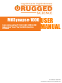
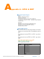
O P E R AT O R ’ S
M A N U A L
MILSYNAPSE 1000 series
RUGGED EMBEDDED COMPUTER SYSTEM
www.ruggedscience.com | [email protected] | toll free: 855-769-9747
MilSynapse-1000 USER
Fanless Advanced Box PC, 2 LAN (4 LAN), 2 HDMI, 6 COM
Onboard Intel® Atom™ Bay Trail E3845 Quad Core
Processor
MANUAL
1.0.2 Edition 2/05/2014
All information is subject to change without notice.
Worldwide Technical Support and Product Information
www.ruggedscience.com
Rugged Science
53 Loveton Circle, Suite 203 Sparks, Maryland, USA 21152
Tel: +1 (855) 769-9747
Fax: +1 (443) 595-8390
For further support information, refer to the Technical Support and Professional
Services appendix. To comment on Rugged Science documentation, refer to the
Rugged Science web site at www.ruggedscience.com.
© 2014 RUGGED SCIENCE All rights reserved.
Record of Revision
Version
V1.0.0
V1.0.1
V1.0.2
Date
Jan 07, 2014
Jan 20, 2014
Feb 05, 2014
Page
All
p30
p16-19
Description
Preliminary Release
GPS Module
Rear Panel DC-IN
Remark
Disclaimer
This manual is intended to be used as a practical and informative guide only and
is subject to change without prior notice. It does not represent commitment from
Rugged Science. Rugged Science shall not be liable for direct, indirect,
special, incidental, or consequential damages arising out of the use of the
product or documentation, nor for any infringements upon the rights of third
parties, which may result from such use.
Declaration of Conformity
FCC
This equipment has been tested and found to comply with the limits for a Class A
digital device, pursuant to part 15 of the FCC Rules. These limits are designed to
provide reasonable protection against harmful interference when the equipment is
operated in a commercial environment. This equipment generates, uses, and can
radiate radio frequency energy and, if not installed and used in accordance with
the instruction manual, may cause harmful interference to radio communications.
Operation of this equipment in a residential area is likely to cause harmful
interference in which case the user will be required to correct the interference at
his own expense.
CE
The product(s) described in this manual complies with all applicable European
Union (CE) directives if it has a CE marking. For computer systems to remain CE
compliant, only CE-compliant parts may be used. Maintaining CE compliance
also requires proper cable and cabling techniques.
Copyright and Trademarks
This document contains proprietary information protected by copyright. All rights
are reserved. No part of this document may be reproduced by any mechanical,
electronic, or other means in any form without prior written permission of
the manufacturer. Company/product names mentioned herein are used for
identification
©RUGGED SCIENCE MilSynapse 1000 Series Advanced Box PC User Manual
iv
Order Information
Part Number
MilSynapse 1000
Description
Fanless Advanced Box PC, 2 Lans, 2 HDMI, 6 COM (2 Isolated COM), 8
GPIO, 5 USB, Terminal Block, Onboard IntelC Atom™ Bay Trail E3845
Quad Core Processor
Optional Accessories
Part Number
Description
DDR3L8G
Kingston® DDR3L-1600 8G RAM
DDR3L4G
Kingston® DDR3L-1600 4G RAM
M340L-W28M1
DDR3L 4GB 1333 | 1066MHz RAM, Micron® Chip, Wide Temperature -40°C
~ +85°C
Onboard GPS Module u-blox NEO GPS Module with Antenna and Cables Pre-Installed
PWA-60W
60W, 12V 100V AC to 240V AC Power Adapter for DC-Jack
PWA-60WP3
60W, 24V 100V AC to 240V AC Power Adapter for Terminal Block
WiFi module w/
Antenna
WiFi module (Intel N6205) with antenna and cables pre-installed
3G Module w/ Antenna 3G module (Sierra MC8090) with Antenna and cables pre-installed
4G Module w/ Antenna Sierra MC7710 with Antenna and cables pre-installed
v
iv
iv
iv
iv
iv
v
v
1
1.1 Overview
1.2 Product Specification
1
2
2
3
4
1.3 Supported CPU List
1.4 Mechanical Dimension
5
6
9
2.2.1 Power, HDD LED Indicator
2.2.2 Power Button
2.2.3 Rest Tact Switch
2.2.4 Ethernet Ports
2.2.5 VGA Connector
2.2.6 Dual HDMI Connectors
2.2.7 Triple USB 3.0 Ports
2.2.8 Dual USB 2.0 Ports
2.2.9 Eight Bits DIO
2.2.10 Audio Connectors
10
10
11
11
12
13
13
14
14
15
2.1 Packing List
2.2 Front Panel I/O Functions
9
9
2.3 Rear Side Exernal I/O Connectors
16
2.4 Main Board Expansion Connectors
20
2.3.1 Serial Ports COM1 and COM2
2.3.2 Serial Ports COM3 and COM4
2.3.3 Isolated Serial Port COM5 | COM6
2.3.4 DC-IN 9~28V 3.5Ø DC Jack or Terminal Block
2.4.1 PANEL 1 Miscellaneous Pin Header
2.4.2 CN24, CN25, J2 LVDS
2.4.3 CN21 SATA II Connector & J1 SATA Power
2.4.4 CN23 mSATA Connector
2.4.5 CN20, CN22, mini-PCIe Connectors
2.4.6 CN29 GPIO
2.4.7 Battery
2.4.8 GPS Module
17
17
18
19
22
23
24
25
27
28
29
30
Connector
2.5 Main Board Jumper Setting
31
2.5.1 JP1(A) CMOS Clear Jumper Setting
2.5.2 JP1(B) ME Clear Jumper Setting
2.5.3 JP2 LVDS Backlight Power Selection
32
33
34
vi
35
40
35
36
38
4.1 BIOS Settings
40
4.1.1 Main Menu
40
4.2 Advanced Function
41
4.3 Chipset Function
50
4.4 Boot Function
52
4.5 Save & Exit
53
4.2.1 ACPI Setting
4.2.2 Serial Port 1 Configuration
4.2.3 Serial Port 2 Configuration
4.2.4 Serial Port 3 Configuration
4.2.5 Serial Port 4 Configuration
4.2.6 Serial Port 5 Configuration
4.2.7 Serial Port 6 Configuration
4.2.8 PPM Configuration
4.2.9 CPU Configuration
4.2.10 IDE Configuration
41
42
43
44
45
46
47
48
48
49
4.3.1 Display Configuration
4.3.2 Power Loss Configuration
50
51
4.4.1 Change Boot Configuration
52
4.5.1 1.5.1. Reload Default BIOS Value
53
54
G
1
General Introduction
1.1 Overview
MilSynapse 1000 series are equipped with Intel®
Quad-Core Atom™ E3800 (formerly codenamed Bay
Trail) processor family (1.91GHz) and DDR3L single
channel 8GB ram, 2 HDMI display, 2 RS-232, 2
RS-232/422/485, 2 isolated RS-232/422/485, 2 GbE LANs,
one 2.5” SATA 3Gp/s SSD/HDD tray, 3 USB 3.0 ports, 2
USB 2.0, and 2 miniPCI-express.
MilSynapse 1000 series is in fanless smart form factor and
capable of operating under wide temperatures from -25°C
to +70°C for harsh environments.With cutting-edge
graphics and computing technologies, MilSynapse 1000
series enable to present high quality resolution 3D display
as low power consumption.
Design with 6 COM to satisfy various applications’
control and connection requirements, MilSynapse 1000
series still keep fanless and wide operation temperature
plus with EN50155 standard and cable-less arrangement
for industrial harsh environment.
MilSynapse 1000 series is ideal for information display
in
harsh
environment,
automation
networking
communication, IOT (Internet of Things), In-Vehicle
Infotainment (IVI) systems, and M2M (Machine to Machine)
applications.
Product Introduction
1
1.2 Product Specification
1.2.1 Specifications of MilSynapse 1000
System
Processor
Chipset
Memory
Video
Audio
Software Support
I/O Ports
Serial Interface
LAN
USB
GPIO
Mini PCIe Slot
Power Supply
Power Input
Power Output
Intel® Atom™ Quad Core Valleyview (Bay Trail) Processor (E3845 1.91GHz)
Valleyview SoC
1 DDR3L 1600 SODIMM, Max. 8Gb
1 DB 15 VGA
2 HDMI 1.4
Optional BOM: LVDS 48bit
1 Mic-In, 1 Line-Out
Windows 8, Windows 7, WES7
6 COM Ports; 2 RS-232, 4 RS-232/422/485
2 Isolated RS-232/422/485
2 Intel® GbE WG82574L
3 USB 3.0, 2 USB 2.0
8 GPIO
miniPCIe Socket (PCIe+USB +SIM card socket)
miniPCIe Socket (PCIe+USB)
mSATA Socket
3 Pre-Cast Holes for Antenna
Terminal Block
ATX: 2-Pin Remote Power On/Off Switch
Optional BOM: On-Board Power Input for PPC
On-Board 12V
Storage
SATA HDD
mSATA
1 SATA II Ports at 3.0Gb/s
1 miniPCIe(full size) Supports mSATA
Watchdog Timer
GPS
Reset: 1 to 255 sec / min Per Step
On-Board GPS Module (Optional)
Dimension (W x L x H)
Weight
Mounting
Design
257mm x 141mm x 48mm (10.1” x 5.6” x 1.9”)
2.1Kg (4.6 lb)
Wall-mount by Mounting Bracket
Compact
Operating Temperature
Storage Temperature
-25°C to 70°C (-13°F to 157°F)
-40°C to 85°C (-40°F to 185°F)
Humidity
Shock
Vibration
10% to 95% Humidity, Non-condensing
Operating, 50 Gms, Half-Sine 11 ms Duration (w / SSD, According to IEC60068-2-27)
Random: 5 Grms @ 5-500Hz according to IEC68-2-64
Sinusoidal: 5 Grms @5-500 Hz according to IEC68-2-64
CE, FCC, EN50155, RoHS
Other
Mechanical
Environmental
EMC
©RUGGED SCIENCE MilSynapse 1000 Series Advanced Box PC User Manual
Product Introduction
2
1.3 Supported CPU List
MilSynapse 1000 series is based on Intel® Atom™ Bay
Trail platform and accepts the following Bay Trail-I
Family processors.
E3845 and E3815 are selected in MilSynapse
1000 series standard models, and the rest is available
upon project-base.
Processor Core CPU Freq Gfx Freq (MHz)
No.
Count (GHz)
Nominal/Turbo
E3845
4C
1.91GHz 542/792
TDP
E3827
2C
1.75GHz 542/792
8W
E3826
2C
1.46GHz 533/667
7W
E3825
2C
1.33 GHz 533 (No Turbo)
6W
E3815
1C
1.46 GHz 400 (No Turbo)
5W
Product Introduction
10W
5
1.4 Mechanical Dimension
Figure 1.1 MilSynapse 1000
257 (10.1”)
141
(5.6”)
257 (10.1”)
141 (5.6”)
48
(1.9”)
48
(1.9”)
257 (10.1”)
124 (4.9”)
86
(3.4”)
71
(2.8”)
©RUGGED SCIENCE MilSynapse 1000 Series Advanced Box PC User Manual
141
(5.6”)
Product Introduction
6
2
Getting to Know Your MilSynapse 1000
2.1 Packing List
Item
Description
1 2
Qty
1
Accessory box, which contains
• Rugged Science Drivers & Utilities DVD
• Wall-mounting bracket
• M4 screws for wall-mounting bracket
• 2-pin pluggable terminal block
1
2
4
2
2.2 Front Panel I/O Functions
On MilSynapse 1000 series, all I/O connectors are
located on front panel and rear panel. Most general
computer connectors (i.e. audio, USB, HDMI, VGA
and etc.) are placed on the front panel.
9
Getting to Know Your MilSynapse 1000
2.2.1 Power, HDD LED Indicator
Yellow-HDD LED: A hard disk / CFast LED. If the LED
is on, it indicates that the system’s storage is functional.
If it is off, it indicates that the system’s storage is not
functional. If it is flashing, it indicates data access
activities.
Green-Power LED: If the LED is solid green, it indicates
that the system is powered on.
2.2.2 Power Button
The power button is a non-latched switch with dual color
LED (Blue/Orange) for indication S0, S3 and S5 status.
Power button dual-color LED indicator:
Status
S0
S3, S5
LED Display System Situation
Solid Blue
System working
Solid Orange Suspend to RAM, System off
with standby power
To turn on the MilSynapse 1000 series, press the
power button and the blue LED is lighted up.To turn off
the MilSynapse 1000 series, you can either issue a
shutdown command in OS, or just simply press the
power button.
In case of system halts, you can press and hold
the power button for 4 seconds to compulsorily shut
down the system.Please note that a 4 seconds interval
is kept by the system between two on/off operations
(i.e. once turning off the system, you shall wait for 4
seconds to initiate another power-on operation).
©RUGGED SCIENCE MilSynapse 1000 Series Advanced Box PC User Manual
Getting to Know Your MilSynapse 1000 10
2.2.3 Rest Tact Switch
It is a hardware reset switch. Use this switch to reset
the system without turning off the power. Momentarily
pressing the switch will activate a reset.
2.2.4 Ethernet Ports
The 10/100/1000 Mbps Ethernet LAN ports 1 and 2 use
8-pin RJ-45 connectors. LNA1 and LAN2 are equipped
with Intel® 82574L controllers.
Using suitable RJ-45 cable, you can connect
MilSynapse 1000 series system to a computer, or
to any other piece of equipment that has an
Ethernet connection, for example, a hub or a
switch. Moreover, both of them have Wake-onLAN
and
pre-boot
Execution
Environment
capabilities.
The following diagram shows the pinouts for LAN1 and
LAN2
ports.10 / 100 Mbps
Pin No.
1000 Mbps
1
E_TX+
MDI0_P
2
E_TXMDI0_N
3
E_RX+
MDI1_P
4
---MDI2_P
5
----MDI2_N
6
E_RXMDI1_N
7
----MDI3_P
8
-----MDI3_N
The Ethernet ports use standard RJ-45 jack connectors
with LED indicators on the front side to show Active/
Link status and Speed status. The LED indicators on
11
Getting to Know Your MilSynapse 1000
the right bottom corners glow a solid green color when
the cable is properly connected to a 100 Mbps Ethernet
network. The LED indicator on the left bottom corner
will flash on and off when Ethernet packets are being
transmitted or received.
The LED indicators on the right bottom corners glow a
solid orange color when the cable is properly connected
to a 1000 Mbps Ethernet network. The LED indicator on
the left bottom corner will flash on and off when Ethernet
packets are being transmitted or received.
1
8
Location
10 Mbps
100 Mbps
1000 Mbps
Right Bottom off
Solid Green Solid
LED
Orange
Left Bottom Flash Yellow Flash Yellow Flash Yellow
LED
2.2.5 VGA Connector
The MilSynapse 1000 series comes with a DB15
female connector on the front panel to connect a VGA
monitor. To ensure that the monitor image remains
clear, be sure to tighten the monitor cable after
connecting it to the MilSynapse 1000. The VGA
output mode supports up to 2560x1600 resolutions.
The pin assignments of the VGA connector are
shown below.
Pin Description
No.
1
Red Color Signal
2
Green Color Signal
3
Blue Color Signal
4
NC
5
1
5
Ground
10
6
15
11
6
VGA Detect
©RUGGED SCIENCE MilSynapse 1000 Series Advanced Box PC User Manual
Getting to Know Your MilSynapse 1000 12
Pin
No.
7
8
9
10
11
12
13
14
15
Description
Ground
Ground
VCC
Ground
NC
DDC-DATA
H-Sync.
V-Sync.
DDC-CLK
2.2.6 Dual HDMI Connectors
Each HDMI output mode supports up to 2560x1600
resolutions. The HDMI mode is automatically selected
according to the display device connected.
2.2.7 Triple USB 3.0 Ports
The MilSynapse 1000 series comes with 3 USB
3.0 hosts on the front panel. These USB 3.0 ports
allow data transfers up to 5 Gb/s. The
controller supports SuperSpeed (SS), high-speed
(HS), full-speed (FS) and low-speed (LS) traffic on the
bus.
13
Getting to Know Your MilSynapse 1000
2.2.8 Dual USB 2.0 Ports
The MilSynapse 1000 series comes with 2 USB
2.0 hosts on the front panel. The USB interface
supports Plug and Play, which enables you to
connect or disconnect a device whenever you want,
without turning off the system.
The hosts can be used for an external flash disk or
hard drive for storing large amounts of data. You can
also use these USB hosts to connect to a keyboard or
a mouse. The following diagram shows the pinouts for
USB ports.
1
Pin Number
USB1
USB2
1
+5V
+5V
2
3
2
USB1USB2-
4
3
USB1+
USB2+
4
GND
GND
2.2.9 Eight Bits DIO
©RUGGED SCIENCE MilSynapse 1000 Series Advanced Box PC User Manual
Getting to Know Your MilSynapse 1000 14
The MilSynapse 1000 series offers an 8-bit DIO
connector. Each bit internal pull up a weak resistor
to +V3.3_SB. Each bit can be configured for DO or DI
you can find the setting in BIOS.
Pin
No.
1
2
3
4
5
6
7
8
9
Definition
GPIO 0
GPIO 1
GPIO 2
GPIO 3
GND
GPIO 4
GPIO 5
GPIO 6
GPIO 7
Mapping to SIO GPIO
Function
SIO_GPI70
SIO_GPI71
SIO_GPI72
SIO_GPI73
GND
SIO_GPI74
SIO_GPI75
SIO_GPI76
SIO_GPI76
2.2.10 Audio Connectors
The MilSynapse 1000 series offers stereo audio
connectors of MIC and Line-In. The audio chip
controller is by ALC892 which is compliant with the
Intel® Azalia standard. To utilize the audio function in
Windows, you need to install corresponding drivers for
Realtek® ALC892 codec.
15
Getting to Know Your MilSynapse 1000
2.3 Rear Side Exernal I/O Connectors
Figure 2.3.1 MilSynapse 1000 Rear Panel
©RUGGED SCIENCE MilSynapse 1000 Series Advanced Box PC User Manual
Getting to Know Your MilSynapse 1000 16
2.3.1 Serial Ports COM1 and COM2
COM1 and COM2 are RS-232 only and provide up to
115200 bps baud rates. The pin assignments are shown
in the following table:
Serial Port
Pin No.
RS-232
1
DCD
2
RXD
3
TXD
4
DTR
COM1, 2
5
GND
6
DSR
7
RTS
8
CTS
9
RI
2.3.2 Serial Ports COM3 and COM4
COM3 and COM4 can be configured for RS-232, RS422, or RS-485 with auto flow control communication.
Serial Port 3 & 4 default setting are RS-232, if you want
to use RS-422 or RS-485, you can find the setting in
BIOS.
BIOS Setting
COM3 | COM4
Function
RS-232
RS-422 (5-wire)
RS-422 (9-wire)
RS-485
RS-485 w/z auto-flow control
17
Getting to Know Your MilSynapse 1000
The pin assignments are shown in the following table:
Serial
Pin
RS-232 RS-422 RS-422 RS-485
Port
No.
(5-Wire) (9-Wire) (3-Wire)
1
DCD
TXDTXDDATA2
RXD
TXD+
TXD+
DATA+
3
TXD
RXD+ RXD+ ----------4
DTR
RXDRXD----------3.4
5
GND
GND
GND
GND
6
DSR
----------- RTS----------7
RTS
----------- RTS+
----------8
CTS
----------- CTS+
----------9
RI
----------- CTS-----------
2.3.3 Isolated Serial Port COM5 | COM6
Only MilSynapse 1000 provides Isolated serial
ports COM5 | COM6. COM5 and COM6 can be
configured for RS-232, RS-422, or RS-485 with
auto flow control communication. Serial Port 5 and
6 default setting are RS-232, if you want to use
RS-422 or RS-485, you can find the setting in BIOS.
BIOS Setting
COM5 | COM6
Function
RS-232
RS-422 (5-wire)
RS-422 (9-wire)
RS-485
RS-485 w/z auto-flow control
The pin assignments are shown in the following table:
©RUGGED SCIENCE MilSynapse 1000 Series Advanced Box PC User Manual
Getting to Know Your MilSynapse 1000 18
Serial
Port
2
Pin No. RS-232 RS-422
(5-Wire)
1
DCD
TXD2
RXD
TXD+
3
TXD
RXD+
4
DTR
RXD5
GND
GND
6
DSR
----------7
RTS
----------8
CTS
----------9
RI
-----------
RS-422
(9-Wire)
TXDTXD+
RXD+
RXDGND
RTSRTS+
CTS+
CTS-
RS-485
(3-Wire)
DATADATA+
--------------------GND
-----------------------------------------
2.3.4 DC-IN 9~28V 3.5Ø DC Jack or Terminal Block
The MilSynapse 1000 series offers 9 to 28 VDC
power input, MilSynapse 1000 Terminal Block, DC
Jack connector. If the power is supplied properly, the
Power LED will light up a solid green.
19
Getting to Know Your MilSynapse 1000
2.4 Main Board Expansion Connectors
The figure below is the top view of the MilSynapse
1000 series main board. It shows the location of the
connectors.
Figure 2.4.1 Internal Connectors and Jumpers
©RUGGED SCIENCE MilSynapse 1000 Series Advanced Box PC User Manual
Getting to Know Your MilSynapse 1000 20
The figure below is the bottom view of the
MilSynapse 1000 series main board.
21
Getting to Know Your MilSynapse 1000
2.4.1 PANEL 1 Miscellaneous Pin Header
These pin headers can be used as a backup for the
following functions: hard drive LED indicator, reset
button, power LED indicator, and power-on/off button.
The front and top panel already provides access to
these functions. The following table shows the pinouts
for Miscellaneous port.
J1 Miscellaneous Pin Header
Group
Pin No.
HDD LED
2
4
RESET BUTTON 6
8
POWER LED
2
4
POWER
6
BUTTON
8
POWER
9
10
©RUGGED SCIENCE MilSynapse 1000 Series Advanced Box PC User Manual
Description
HD_LED+
HD_LEDFP_RST_BTN_N
GND
PWR_LED+
PWR_LED_N
FP_PWR_BTN_N
GND
+V5
+V5_SB
Getting to Know Your MilSynapse 1000 22
2.4.2 CN24, CN25, J2 LVDS
The MilSynapse 1000 series supports Dualchannel 24-bit LVDS Panel up to 1920x1200 pixels
panel
Definition
Pin resolution.
No. CN24 Channel A
CN25 Channel
1
LDDC_CLK
LDDC_CLK
2
LDDC_DATA
LDDC_DATA
3
PANEL_VDD (+3.3V or PANEL_VDD(+3.3V or
+5V by JP2 jumper)
+5V by JP2 jumper)
4
LA_ DATA0_P
LB_ DATA0_P
5
LA_ DATA3_P
LB_ DATA3_P
6
LA_ DATA0_N
LB_ DATA0_N
7
LA_ DATA3_N
LB_ DATA3_N
8
PANEL_VDD (+3.3V or PANEL_VDD (+3.3V or
+5V by JP2 jumper)
+5V by JP2 jumper)
9
GND
GND
10 LA_ DATA1_P
LB_ DATA1_P
11 LA_ CLKP
LB_ CLKP
12 LA_ DATA1_N
LB_ DATA1_N
13 LA_ CLKN
LB_ CLKN
14 GND
GND
15 GND
GND
16 PANEL_BACKLIGHT
PANEL_BACKLIGHT
(+12V)
(+12V)
17 LA_ DATA2_P
LB_ DATA2_P
23
Getting to Know Your MilSynapse 1000
Definition
Pin
No. CN24 Channel A
CN25 Channel
18 PANEL_BACKLIGHT
PANEL_BACKLIGHT
(+12V)
(+12V)
19 LA_ DATA2_N
LB_ DATA2_N
20 GND
GND
The LCD inverter is connected to J2 via a JST 7-pin,
2.5mm connector to provide +5V/+12V power to the
LCD display.
Pin No.
1
2
3
4
5
6
7
Definition
+5V
+12V
+12V
LBKLT_CTL
GND
GND
LBKLT_EN
2.4.3 CN21 SATA II Connector & J1 SATA Power
Connector
©RUGGED SCIENCE MilSynapse 1000 Series Advanced Box PC User Manual
Getting to Know Your MilSynapse 1000 24
The MilSynapse 1000 series features two high
performance Serial ATA II interfaces that eases cabling
to hard drives or SSD with thin and short cables while
application need larger storage capacity.
Pin No.
Definition
1
GND
2
TXP
3
TXN
4
GND
5
RXN
6
RXP
7
GND
The MilSynapse 1000 series is equipped with one
SATA power connector. It supply 5V (1A max.) and
12V (1A max) current to the hard drive or SSD.
CN21 SATA HDD Power Connector
Pin No.
Definition
1
+12V
2
GND
3
GND
4
+5V
2.4.4 CN23 mSATA Connector
25
Getting to Know Your MilSynapse 1000
It is for connecting an eSATA storage device. There
was no clear mechanism to distinguish if a mSATA drive
or a Mini PCI-E device is plugged into the socket until
recently that SATA-IO issued an ECN change (ECN
#045) to re-define pin 43 on mSATA connector as “no
connect” instead of “return current path” ( or GND).
When an mSATA drive is inserted, its pin 43 is “no
connect”, and the respective pin on the socket is
being pulled-up to logic 1. When a Mini PCI-E device
is inserted, its pin 43 forces the respective pin on the
socket to ground, or logic 0.
CN23 mSATA Connector Pin-Out
Pin
No.
51
49
47
45
43
41
39
37
35
Signal
Name
NC
NC
NC
NC
GND
+3.3Vaux
+3.3Vaux
GND
GND
Pin
No.
52
50
48
46
44
42
40
38
36
15
13
11
9
GND
NC
NC
GND
16
14
12
10
©RUGGED SCIENCE MilSynapse 1000 Series Advanced Box PC User Manual
Signal
Pin Signal
Name
No. Name
+3.3Vaux 33 SATA_TXp
GND
31 SATA_TXn
+1.5V
29 GND
NC
27 GND
NC
25 SATA_RXp
NC
23 SATA_RXn
GND
21 GND
NC
19 NC
NC
17 NC
Mechanical Key
NC
7 NC
NC
5 NC
NC
3 NC
NC
1 NC
Pin Signal
No. Name
34 GND
32 NC
30 NC
28 +1.5V
26 GND
24 +3.3Vaux
22 NC
20 NC
18 GND
8
6
4
2
NC
1.5V
GND
3.3Vaux
Getting to Know Your MilSynapse 1000 26
2.4.5 CN20, CN22, mini-PCIe Connectors
CN20 Mini-PCIe Connector Pin-Out
Pin
No.
51
49
47
45
43
41
39
37
35
Signal
Name
NC
NC
NC
NC
GND
+3.3Vaux
+3.3Vaux
GND
GND
Pin
No.
52
50
48
46
44
42
40
38
36
Signal
Name
+3.3Vaux
GND
+1.5V
NC
NC
NC
GND
USB_D+
USB_D-
Pin
No.
33
31
29
27
25
23
21
19
17
Signal
Name
PETp0
PETn0
GND
GND
PERp0
PERn0
GND
NC
NC
15
13
11
9
GND
REFCLK+
REFCLKGND
16
14
12
10
Mechanical Key
UIM_VPP 7 CLKREQ#
UIM_RST 5 NC
UIM_CLK 3 NC
UIM_DATA 1 WAKE#
Pin Signal
No. Name
34 GND
32 SMB_DATA
30 SMB_CLK
28 +1.5V
26 GND
24 +3.3Vaux
22 PERST#
20 NC
18 GND
8
6
4
2
UIM_PWR
1.5V
GND
3.3Vaux
CN22 Mini-PCIe Connector Pin-Out
Pin
No.
51
49
47
45
43
Signal
Name
NC
NC
NC
NC
GND
Pin
No.
52
50
48
46
44
Signal
Name
+3.3Vaux
GND
+1.5V
NC
NC
Pin
No.
33
31
29
27
25
Signal
Name
PETp0
PETn0
GND
GND
PERp0
Pin Signal
No. Name
34 GND
32 SMB_DATA
30 SMB_CLK
28 +1.5V
26 GND
27
Getting to Know Your MilSynapse 1000
Pin
No.
41
39
37
35
Signal
Name
+3.3Vaux
+3.3Vaux
GND
GND
Pin
No.
42
40
38
36
15
13
11
9
GND
REFCLK+
REFCLKGND
16
14
12
10
Signal
Pin Signal
Name
No. Name
NC
23 PERn0
GND
21 GND
USB_D+ 19 NC
USB_D17 NC
Mechanical Key
NC
7 CLKREQ#
NC
5 NC
NC
3 NC
NC
1 WAKE#
Pin Signal
No. Name
24 +3.3Vaux
22 PERST#
20 NC
18 GND
8
6
4
2
NC
1.5V
GND
3.3Vaux
2.4.6 CN29 GPIO
These pin headers can be used as a backup for the The
MilSynapse 1000 series offers 8 programmable I/O
within TTL 3.3V tolerance. If the GPIO is logic high,
it indicates that the mapping SIO GPIO pin is logic
high level. If the GPIO is logic low, it indicates that the
mapping SIO GPIO pin is logic low level.
Pin No.
1
2
3
4
©RUGGED SCIENCE MilSynapse 1000 Series Advanced Box PC User Manual
SIO GPIO Function
SIO_GPIO77
SIO_GPIO76
SIO_GPIO75
SIO_GPIO74
Getting to Know Your MilSynapse 1000 28
Pin No.
5
6
7
8
9
SIO GPIO Function
SIO_GPIO73
SIO_GPIO72
SIO_GPIO71
SIO_GPIO70
GND
2.4.7 Battery
The MilSynapse 1000 series’ real-time clock is
powered by a lithium battery. It is Equipped with
Panasonic BR2032 190mAh lithium battery. It is
recommended that you not replace the lithium battery
on your own. If the battery needs to be changed,
please contact the Rugged Science RMA service
team.
29
Getting to Know Your MilSynapse 1000
2.4.8 GPS Module
The MilSynapse 1000 series offers a u-blox NEO-7 GPS/
GNSS modules (can upgrade to NEO-8 ) and 2.0mm
diameter I-PEX antenna connector with 3.3 voltage
power. Antenna circuit as follows.
©RUGGED SCIENCE MilSynapse 1000 Series Advanced Box PC User Manual
Getting to Know Your MilSynapse 1000 30
2.5 Main Board Jumper Setting
The figure below is the top view of the MilSynapse
1000 series main board. It shows the location of the
jumpers.
You may configure your card to match the needs of
your application by setting jumpers. A jumper is a metal
bridge used to close an electric circuit.
It consists of two metal pins and a small metal clip (often
protected by a plastic cover) that slides over the pins to
connect them.
To “close” a jumper, you connect the pins with the clip.
To “open” a jumper, you remove the clip. Sometimes a
jumper will have three pins, labeled 1, 2 and 3. In this
case you would connect either pins 1 and 2, or 2 and 3.
31
Getting to Know Your MilSynapse 1000
2.5.1 JP1(A) CMOS Clear Jumper Setting
Setting
1-3
3-5
©RUGGED SCIENCE MilSynapse 1000 Series Advanced Box PC User Manual
Description
Normal (Default)
Clear CMOS
Getting to Know Your MilSynapse 1000 32
2.5.2 JP1(B) ME Clear Jumper Setting
Setting
2-4
4-6
Description
Normal (Default)
Clear ME
33
Getting to Know Your MilSynapse 1000
2.5.3 JP2 LVDS Backlight Power Selection
JP2 provides LVDS voltage selection function, closing
Pin 1, 2 is for 3.3V LVDS power input; closing Pin 2, 3 is
for 5V LVDS power input.
Setting
1-2
2-3
©RUGGED SCIENCE MilSynapse 1000 Series Advanced Box PC User Manual
Description
+3.3V (Default)
+5V
Getting to Know Your MilSynapse 1000 34
3
System Setup
3.1 Install DDR3 / DDR3L SODIMM Modules
Step1.
Put the MilSynapse 1000
series upside down on a
flat surface. You can see
the “Pet-Door” exposed.
Use a Philips screwdriver
to loose the M3 flat-head
screw on the “Pet-Door”.
Step2.
Remove the “Pet-Door”
and you can see a DDR3
SODIMM socket exposed.
System Setup
35
Step3.
Tile the SODIMM module
and insert it to the SODIMM
socket.
As it’s firmly contacted with
socket connectors, press it
down until the clamps of the
socket snap into the latching
position of SODIMM module.
3.2 Install SSD | HDD
Step1.
Put the MilSynapse 1000
series upside down on a
flat surface. You can see
the “Pet-Door” exposed.
Use a Philips screwdriver
to loose the M3 flat-head
screw on the “Pet-Door”.
Step2.
Remove the “Pet-Door”
and you can see a DDR3
SODIMM socket exposed.
©RUGGED SCIENCE MilSynapse 1000 Series Advanced Box PC User Manual
System Setup
36
Step3.
Place the HDD into the
bracket and gently push it
down to make it contact with
thermal pad. Use a Philips
screwdriver to fix the HDD
with M3 screws. Please note
that the HDD must be placed
in the right direction as
below.
Step4.
P u l l o u t t h e S ATA c a b l e
inside the chassis and
connect it to HDD.
SATA Connector of HDD
System Setup
37
3.3 Mount Your MilSynapse 1000
Installation Method 1
©RUGGED SCIENCE MilSynapse 1000 Series Advanced Box PC User Manual
System Setup
38
Installation Method 2
System Setup
39
4
BIOS and Driver
4.1 BIOS Settings
The board uses UEFI BIOS that is use Serial Peripheral
Interface (SPI) Flash. The SPI Flash contains the BIOS
Setup program, POST, the PCI auto-configuration utility,
LAN, EEPROM information, and Serial port support. The
BIOS setup program is accessed by pressing the <Del>
key after the Power-On Self-Test (POST) memory test
begins and before the operating system boot begins. The
menu bar is shown below.
Figure 4.1: BIOS Menu Bar
4.1.1 Main Menu
©RUGGED SCIENCE MilSynapse 1000 Series Advanced Box PC User Manual
BIOS and Driver
40
Figure 4.1.1: BIOS Main screen
System Time / Date : Press “TAB” key to switch subitems of value .Then press “ +” key or “-“ key number
key for modify value.
In this page , you could make sure you CPU type and
DRAM type that you are install into this system.
4.2 Advanced Function
4.2.1 ACPI Setting
Figure 4.2.1: ACPI Setting setup screen
BIOS and Driver
41
Enable ACPI Auto Configuration: This system support
ACPI function as auto process. You should Enable /
Disable that depend as your O.S.
Enable Hibernation: It is able to use Hibernate function
if O.S support. But some Operation system maybe not
effective with this function.
ACPI Sleep state: Select sleep state while SUSPEND
button pressed.
4.2.2 Serial Port 1 Configuration
Advanced->IT8786E Super IO Configuration->Serial Port 1 Configuration
Figure 4.2.2: Serial Port 2 Setup screen
Serial Port :
Enable or Disable Serial port.
Device Setting:
Current IO addresses and interrupts resource of Serial
Port.
Change Settings :
Select another device setting.
Here have 6 options :
Auto
IO=3F8h; IRQ=4;
IO=3F8h; IRQ=3,4,5,6,7,8,9,10,11,12;
IO=2F8h; IRQ=3,4,5,6,7,8,9,10,11,12;
IO=3E8h; IRQ=3,4,5,6,7,8,9,10,11,12;
IO=2E8h; IRQ=3,4,5,6,7,8,9,10,11,12;
©RUGGED SCIENCE MilSynapse 1000 Series Advanced Box PC User Manual
BIOS and Driver
42
4.2.3 Serial Port 2 Configuration
Advanced->IT8786E Super IO Configuration->Serial Port 1 Configuration
Figure 4.2.3: Serial Port 1 Setup screen
Serial Port :
Enable or Disable Serial port.
Device Setting:
Current IO addresses and interrupts resource of Serial
Port.
Change Settings :
Select another device setting.
Here have 6 options :
Auto
IO=3F8h; IRQ=4;
IO=3F8h; IRQ=3,4,5,6,7,8,9,10,11,12;
IO=2F8h; IRQ=3,4,5,6,7,8,9,10,11,12;
IO=3E8h; IRQ=3,4,5,6,7,8,9,10,11,12;
IO=2E8h; IRQ=3,4,5,6,7,8,9,10,11,12;
BIOS and Driver
43
4.2.4 Serial Port 3 Configuration
Advanced->IT8786E Super IO Configuration->Serial Port 1 Configuration
Figure 4.2.4: Serial Port 1 Setup screen
Serial Port :
Enable or Disable Serial port.
Device Setting:
Current IO addresses and interrupts resource of Serial
Port.
Change Settings :
Select another device setting.
Here have 6 options :
Auto
IO=3F8h; IRQ=4;
IO=3F8h; IRQ=3,4,5,6,7,8,9,10,11,12;
IO=2F8h; IRQ=3,4,5,6,7,8,9,10,11,12;
IO=3E8h; IRQ=3,4,5,6,7,8,9,10,11,12;
IO=2E8h; IRQ=3,4,5,6,7,8,9,10,11,12;
Interface Modes :
Select UART transfer and receive protocol
Here have 3 options :
RS-232 Mode
RS-422 Mode
RS-485 Mode
©RUGGED SCIENCE MilSynapse 1000 Series Advanced Box PC User Manual
BIOS and Driver
44
4.2.5 Serial Port 4 Configuration
Advanced->IT8786E Super IO Configuration->Serial Port 1 Configuration
Figure 4.2.5: Serial Port 1 Setup screen
Serial Port :
Enable or Disable Serial port.
Device Setting:
Current IO addresses and interrupts resource of Serial
Port.
Change Settings :
Select another device setting.
Here have 6 options :
Auto
IO=3F8h; IRQ=4;
IO=3F8h; IRQ=3,4,5,6,7,8,9,10,11,12;
IO=2F8h; IRQ=3,4,5,6,7,8,9,10,11,12;
IO=3E8h; IRQ=3,4,5,6,7,8,9,10,11,12;
IO=2E8h; IRQ=3,4,5,6,7,8,9,10,11,12;
Interface Modes :
Select UART transfer and receive protocol
Here have 3 options :
RS-232 Mode
RS-422 Mode
RS-485 Mode
BIOS and Driver
45
4.2.6 Serial Port 5 Configuration
Advanced->IT8786E Super IO Configuration->Serial Port 1 Configuration
Figure 4.2.6: Serial Port 1 Setup screen
Serial Port :
Enable or Disable Serial port.
Device Setting:
Current IO addresses and interrupts resource of Serial
Port.
Change Settings :
Select another device setting.
Here have 6 options :
Auto
IO=3F8h; IRQ=4;
IO=3F8h; IRQ=3,4,5,6,7,8,9,10,11,12;
IO=2F8h; IRQ=3,4,5,6,7,8,9,10,11,12;
IO=3E8h; IRQ=3,4,5,6,7,8,9,10,11,12;
IO=2E8h; IRQ=3,4,5,6,7,8,9,10,11,12;
Interface Modes :
Select UART transfer and receive protocol
Here have 3 options :
RS-232 Mode
RS-422 Mode
RS-485 Mode
©RUGGED SCIENCE MilSynapse 1000 Series Advanced Box PC User Manual
BIOS and Driver
46
4.2.7 Serial Port 6 Configuration
Advanced->IT8786E Super IO Configuration->Serial Port 1 Configuration
Figure 4.2.7: Serial Port 1 Setup screen
Serial Port :
Enable or Disable Serial port.
Device Setting:
Current IO addresses and interrupts resource of Serial
Port.
Change Settings :
Select another device setting.
Here have 6 options :
Auto
IO=3F8h; IRQ=4;
IO=3F8h; IRQ=3,4,5,6,7,8,9,10,11,12;
IO=2F8h; IRQ=3,4,5,6,7,8,9,10,11,12;
IO=3E8h; IRQ=3,4,5,6,7,8,9,10,11,12;
IO=2E8h; IRQ=3,4,5,6,7,8,9,10,11,12;
Interface Modes :
Select UART transfer and receive protocol
Here have 3 options :
RS-232 Mode
RS-422 Mode
RS-485 Mode
BIOS and Driver
47
4.2.8 PPM Configuration
Figure 4.2.8: Trusted Computing setup screen
EIST :
Enables or Disables Intel Speed function , once you
enabled it , you could use the Intel Turbo Boost software
to monitor you CPU performance. Please refer to CPU
check list.
4.2.9 CPU Configuration
Advanced->CPU Configuration->Socket 0 CPU Information
Figure 4.2.9: Trusted Computing setup screen
©RUGGED SCIENCE MilSynapse 1000 Series Advanced Box PC User Manual
BIOS and Driver
48
Intel® Virtualization Technology :
This is for Virtualization Application or platform usage,
when enabled, a VMM can utilize the additional hardware
capabilities provided by Vanderpool Technology,
4.2.10 IDE Configuration
Figure 4.2.10: SATA Configuration setup screen
Serial-ATA(SATA) :
Enables or Disables integrate SATA controller for Storage
device use.
SATA Mode Selection:
Determines how the SATA transfer mode for operate.
Here have three option for choice [IDE] / [AHCI] .
Serial Port 0~1 :
This system offers two SATA port for connection SATA
device.
BIOS and Driver
49
4.3 Chipset Function
4.3.1 Display Configuration
Chipset->North Bridge->Intel IGD Configuration->Primary Display
Figure 4.3.1: Network Setup screen
Primary Display:
Select which Display module you would like to you on
current system.
[PCI] : System display function will be change to internal PCI
or PCIe bus.
[IGD] : Use Internal Intel HD Graphics unit for unique display
output.
©RUGGED SCIENCE MilSynapse 1000 Series Advanced Box PC User Manual
BIOS and Driver
50
4.3.2 Power Loss Configuration
Chipset->South Bridge
Figure 4.3.2: Power Loss Setup screen
Restore AC Power Loss :
[Power Off ] : When plug-in the power source , system will
keep on SB mode.
[Power On ] : When plug-in the power source , system will
auto booting .
[Last State ] : When plug-in the power source , system will
keep on last power status.
BIOS and Driver
51
4.4 Boot Function
4.4.1 Change Boot Configuration
Figure 4.4.1: Boot Setup screen
Boot option:
When you press “Enter” , you can select which device you
would like to boot.
©RUGGED SCIENCE MilSynapse 1000 Series Advanced Box PC User Manual
BIOS and Driver
52
4.5 Save & Exit
4.5.1 1.5.1. Reload Default BIOS Value
Figure 4.5.1: Boot Setup screen
Restore Default:
Use the function to restore all BIOS setting, but not include
administrator password and system RTC value.
Save as Use Default:
Uses can use this function to match the target system.
Restore as Use Default:
Restore all BIOS setting to User Default.
BIOS and Driver
53
A
ppendix A : GPIO & WDT
Operation System Support
Linux :
Ubuntu 12.04 LTS or Above
Fedora 16 or Above
And another Linux kernel 2.6.38 and RHL6.0
(* The Linux kernel of RHL , please check RadHat
website first )
Windows :
Windows 7 Home/Professional/MediaCenter/
Windows 8 ( Do not support RT version)
Windows Server 2012
GPIO & WDT Function
The GPIO& WDT are using internal Super IO function.
However, you must entry super I/O configuration mode to
set it.
The output port is set as GPIO 1 on CN13 , reg. index =
0x60
The input port is set as GPIO 4 on CN12 , reg. index =
0x62.
Super I/O special address port = 0x2E
Super I/O special data port = 0x2F
GPIO Logical device is 0x07
Pin No.
1
2
3
4
5
6
7
8
9
©RUGGED SCIENCE MilSynapse 1000 Series Advanced Box PC User Manual
SIO GPIO Function
SIO_GPIO77
SIO_GPIO76
SIO_GPIO75
SIO_GPIO74
SIO_GPIO73
SIO_GPIO72
SIO_GPIO71
SIO_GPIO70
GND
Appendix A
54
A.Entry MB PnP mode.
//write twice 0x87 value.
outportb(Super I/O special address port, 0x87);
outportb(Super I/O special address port, 0x01);
outportb(Super I/O special address port, 0x55);
outportb(Super I/O special address port, 0x55);
B.Located on Logical Device 7
//write 0x07 on Reg [0x07] , this setup must follow Step A.
that can be workable.
outportb(Super I/O special address port, 0x07);
outportb(Super I/O special data port, 0x07);
C.Access the Super I/O register
Base control for write Super I/O register.
outportb(Super I/O special address port, Register Index.);
outportb(Super I/O special data port, update_value);
Base control for read Super I/O register
outportb(Super I/O special address port, Register Index.);
inportb(Super I/O special data port);
//It will return a
BYTE value.
D.Start to Access the MilSynapse 1000 series GPIO
port
Please refer to source code for set_data() and get_data()
function.
Write data to GPO(output) port
set_data( Register Index , update_value);
example :
unsigned char data = 0x82;
set_data( 0xE5 , data);
//Set bit 7 & bit 1 of GPO output port as High
level ,another bit is Low
Read data to GPI(input) port
get_data( Register Index ) //It will return a BYTE value.
example :
unsigned char data
get_data( 0xF1 , data);
//Get GPI(input) port status on input_data variable.
E.WDT ON/OFF and Timer-Counter setting
Refer to GPIO setting of Step A and B. , located Logical
Appendix A
55
0x08 for WDT function.
Reg [0x72] is WatchDog ON/OFF control.
WatchDog On : set_data( 0x30 , 0x01);
WatchDog Off : set_data( 0x30 , 0x00);
Reg [0x73] is WatchDog timer – For WDT Timer out value
WatchDog counter start :
WatchDog counter start :
set_data( 0xF0 , 0x02);
set_data( 0xF0 , 0x00);
Reg [0x72] is WatchDog time-out value, “Reading” this
register returns the current value in the Watch Dog
Counter, not the Watch Dog Timer Time-out value..
WatchDog time-out value:
©RUGGED SCIENCE MilSynapse 1000 Series Advanced Box PC User Manual
set_data( 0xF1 , );
Appendix A
56