1
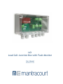
LCI
Load Cell Junction Box with Fault Monitor
User Manual
mantracourt.com
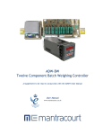
The LCI Load Cell Failure Alarm Manual
Chapter 1 Introduction to the LCI .................................................................................................... 2
Chapter 2 Installing the LCI ........................................................................................................... 3
Figure 2.1 LCI Connection Details ..................................................................................................... 3
Table 2.1 LCI Connections to LCB & ADW15 Details ................................................................................ 3
Chapter 3 Setting up the LCI .......................................................................................................... 4
Sequence of Operations ................................................................................................................. 4
Programmer Keys ......................................................................................................................... 4
Table 3.1 ................................................................................................................................... 4
Password Protection ..................................................................................................................... 4
Configurable Parameters ................................................................................................................ 5
Table 3.2 ................................................................................................................................... 5
The Error Displays on the LCI ........................................................................................................... 5
The Millivolt Display readings on the LCI ............................................................................................. 6
Chapter 4 The Specifications and Parameters of the LCI ....................................................................... 7
Specifications ............................................................................................................................. 7
CE Approvals ............................................................................................................................... 8
Wiring Conditions ......................................................................................................................... 8
W A R R A N T Y ........................................................................................................................... 8
Mantracourt Electronics Limited LC1 User Manual
1
Chapter 1 Introduction to the LCI
Mantracourt Electronics, have introduced the low cost Load Cell Failure Alarm, to provide connection between 1 and
4 load cells to a weighing system, creating a means of constantly monitoring the condition of individual load cells.
Continuous diagnosis of fault conditions prevents the incorrect weighing of product and the subsequent technical
and commercial problems resulting from such situations.
The benefits of the junction box are that any load cell malfunction is immediately reported by an alarm condition,
avoiding incorrect material levels so that there is the continued assurance of correct product quantities.
The avoidance of batch wastage or product recall, reduction in plant downtime and increased safety, together with
aids for installation and commissioning; all contribute to the LCI becoming an essential element for all weighing
systems.
An on board microprocessor provides for a high level of intelligence, the LCI is therefore able to offer a useful range
of features: 1. Load detection; An alarm contact will change state, the Red Alarm LED will indicate and the display will show
the load cell in error and the error code.
An error is detected in any of the following occur:
•
•
•
•
One or more of the load cells are out of balance with the pre-set error band.
Any load cell is operating outside its pre-set range
The load cell excitation voltage drops
Any of the load cells become open or short circuit
2. A display of the mV/V value of each load cell, or the average of the summated mV/V value of all the load cells.
2
Mantracourt Electronics Limited LC1 User Manual
Chapter 2 Installing the LCI
The LCI is provided as single PCB unit, prepared with 4 fixing centres to accommodate M4 screws. Case options are
IP65 ABS (as standard), Stainless steel, or DIN rail mounting.
Installation of the LCI is simplified by the provision of separate, 2 part plug-in connectors for each of the load cell
cables, the indication I/O and alarm relay.
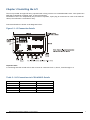
Connection details are shown in the diagrams below:-
Figure 2.1 LCI Connection Details
Setting
mV
1
1d
2
b
3c
2
4a
Alarm
LED
Important Note:
If connecting less than 4 load cells to the LCI start at connector block 1, then 2, 3 and through to 4.
Table 2.1 LCI Connections to LCB & ADW15 Details
LCI
+EX
+S
Scr
-S
-Ex
LCB
+E & +S
+IN
SCR
-IN
-E & -S
ADW15
5&6
4
1
3
1&2
Mantracourt Electronics Limited LC1 User Manual
3
Chapter 3 Setting up the LCI
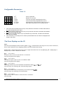
The LCI features a 4 digit Red LED display, where all the various conditions are displayed and 4 programming keys.
On ‘Power Up’, the display will show either ‘good’ or display an Error e.g. ‘1Er5’
Which refers in this example, to Load Cell No.1 with error No.5
Sequence of Operations
Programmer Keys
d
Table 3.1
1
Used to scroll through and change the set up data by displaying mnemonics for
each configurable parameter, followed by the appropriate data and stores data
into non-volatile memory.
b
2
Selects the display digit required. Selection value is indicated by a flashing
digit.
c
3
Increments each selected display digit 0-9, or –9 to 9 for the most significant
digit if sign allowed.
a
4
Resets the display to either the ‘good’ or an error display, saving the current
value into the non-volatile memory.
If during the programming sequence, selection is not completed, the display
will revert to the status message after 2 minutes.
Password Protection
A 4 digit password number must be entered. The number is accessed when ‘PASS’ is displayed. At this point, it is
necessary to enter the factory set number (1111).
4
Mantracourt Electronics Limited LC1 User Manual
Configurable Parameters
Table 3.2
Code
Range
1111
1 to 4
± 50.00
± 50.00
0 to 50.00
0 to 25.0
Function
Security password
Number of load cells
Load cell operating range Minimum (see 1)
Load Cell operating range Maximum (see 2)
Permissible Error band between load cells (see 3)
Time before Alarm trip, set in seconds (see 4)
1. This is the lowest operating level (in mV) of any load cell connected. The alarm will activate if
any load cell falls below this value.
2. This is the highest operating level (in mV) of any load cell connected. The alarm will activate if
any load cell exceeds this value.
3. This is the permissible difference (in mV) between any 2 load cells. The alarm will activate if
this value is exceeded.
4. This is the time (in seconds) an error must be present before the error alarm is displayed and
output via the relay.
The Error Displays on the LCI
Note:
On Power Up the display will show either ‘good’ or (‘ ’). Listed below is the range of errors, which could occur,
due to fault conditions on the weighing system load cells and associated wiring.
Display digits 1 shows which load cell is in error. Digits 2 and 3 show an error by displaying ‘
displays any of 5 fault conditions as follows:-
’. Display digit 4
Error Condition 1
An open or short circuit on the load cell or connectors
(Check wiring and power supply)
Error Condition 2
The load cell input is open circuit or exceeded ± 50mV
(Check wiring and power supply)
Error Condition 3
Operating outside the pre-set maximum and minimum range (
(Check wiring, cell mounting, Max /Min operating ranges)
&
)
Error Condition 4
The load cell balance has exceeded the pre-set balance band (
(Check wiring, cell mounting, Error band values)
)
Error Condition 5
Open circuit of the excitation on the load cell or connectors.
(Check wiring)
Mantracourt Electronics Limited LC1 User Manual
5
Notes:
1. An open or short circuit may cause multiple errors. The display will cycle through multiple errors, displaying
each code for 1 second.
2. To locate faults, start with the load cell, which displays the most errors.
3. The ‘SETTINGS’ button to automatically step through the parameters and their values. During this function
all other keys are disabled.
4. A healthy unit will show red LED ‘OFF’, fault condition ‘ON’
The Millivolt Display readings on the LCI
To view the average of all of the load cell signals, press the ‘mV’ button.
To view the individual load cell signals, hold down the ‘mV’ button, and at the same time press the buttons, 1 to 4
to select each load cell required.
6
Mantracourt Electronics Limited LC1 User Manual
Chapter 4 The Specifications and Parameters of the LCI
Specifications
Faults Monitored
Load Cell out of preset balance range
Load Cell out of pre-set operating range
Low/high excitation
Open circuit to any load cell on each connection
Short circuit on any load cell connection
Internal load cell fault (Bridge Imbalance)
Powering
Indication
By Load Cell Excitation typically 10v DC
1 x 4 digit 7 segment LED display for set up, load cell in error type &
individual total mV outputs
6 buttons for reading & set up
Setting Method
Connections
2
4
1
1
Dimensions
Environmental
Enclosure Material
200 x 120 x 75mm. (PCB dimensions 170 x 100mm excluding mounting
material)
Sealed to IP65 with cable glands & blanking plugs fitted CE
Compliance.
Grey ABS
part terminals, up to 2.5mm² cable
x 5 way, for load cell connection
x 5 way, load cell output
x 3 way, alarm relay contacts
Parameters
Power supply volts from excitation supply
Power supply current from excitation supply 1
Bridge excitation 350R load cell
Bridge resistance (typically 350-700R) each
Bridge sensitivity
Bridge No selectable
Output load
Bandwidth of Junction Box
Zero temperature co-efficient of Junction Box @ 2mV/V
Span temperature co-efficient of Junction Box
Linearity of Junction Box
90 day Stability of Junction Box
90 day Stability of Junction Box
Operating temperature range
Storage temperature range
Humidity
Scan Speed for alarm output (4 cells)
Display, Range
Relay contacts SPCO normally energized
Relay contacts SPCO normally energized
Alarm operating speed for less than 1mV change
mV measurement accuracy individual cell
mV accuracy average reading
Mantracourt Electronics Limited LC1 User Manual
Min
8.2
8
300
1.0
1
1M
-0.0005
-0.0005
-0.0015
-0.001
-0.001
-40
-40
Typical
10
43
10
350
2.0
100
0
0
0
0
0
95
40
-50.00
Max
12
52
12
1000
5.0
4
100G
0.0005
0.0005
0.0015
0.001
0.001
85
95
100
+50.00
500
50
100
-15
-2
+15
+2
Units
Vdc
mA
V
ohms
mV/V
Bridges
ohms
Hz
%V/°C
%/°C
%FSD
%
% FSD
°C
°C
%
mS
mV
mA
V
mS
%
%
7
CE Approvals
European EMC Directive
2004/108/EC
BS EN 61326-1:2006
BS EN 61326-2-3:2006
Wiring Conditions
Load Cell and indication (instrument) cable connections should use individually screened twisted multipair cables
(e.g. FE585 – 646 )
Terminate all screens at SCR. SCR should be connected to a good Earth. The earth connection should be of sufficient
cross sectional area to ensure a low impedance to attenuate RF interference.
WARRANTY
All LCI products from Mantracourt Electronics Ltd., ('Mantracourt') are warranted against defective material and workmanship for a period of (3)
three years from the date of dispatch.
If the 'Mantracourt' product you purchase appears to have a defect in material or workmanship or fails during normal use within the period,
please contact your Distributor, who will assist you in resolving the problem. If it is necessary to return the product to 'Mantracourt' please
include a note stating name, company, address, phone number and a detailed description of the problem. Also, please indicate if it is a
warranty repair.
The sender is responsible for shipping charges, freight insurance and proper packaging to prevent breakage in transit.
'Mantracourt' warranty does not apply to defects resulting from action of the buyer such as mishandling, improper interfacing, operation outside
of design limits, improper repair or unauthorised modification.
No other warranties are expressed or implied. 'Mantracourt' specifically disclaims any implied warranties of merchantability or fitness for a
specific purpose. The remedies outlined above are the buyer’s only remedies. 'Mantracourt' will not be liable for direct, indirect, special,
incidental or consequential damages whether based on the contract, tort or other legal theory.
Any corrective maintenance required after the warranty period should be performed by 'Mantracourt' approved personnel only.
In the interests of continued product development, Mantracourt Electronics Limited reserves the right to alter product specifications without
prior notice.
In the interests of continued product development, Mantracourt Electronics Limited reserves the right to alter product
specifications without prior notice.
Code No. 517-164
8
Mantracourt Electronics Limited LC1 User Manual
Issue 1.6
11.04.14