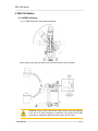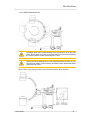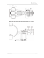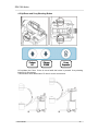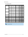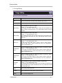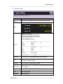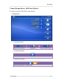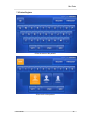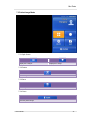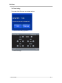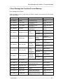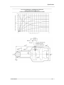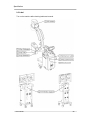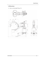
1
Fluoroscopic X-ray System
User’s Manual
Copyright© 2011
2011/ 04 / 25
Document Ver. 1.1
Genoray Co., Ltd.
#512 Byucksan Technopia 434-6 Sangdaewon 1-Dong
Jungwon-Gu, Seongnam-City, Gyeonggi-Do, 462-716 KOREA
Tel: +82-31-740-4100 Fax: +82-31-737-8025
www.genoray.com
Contents
Contents
1. Introduction and Safety .......................................................................................................... 1
1.1 Introduction .................................................................................................................... 1
1.2 Intended Use .................................................................................................................. 1
1.3 Certificate of Warranty .................................................................................................. 1
1.3.1 Range and terms for warranty ................................................................ 1
1.3.2 Requirements on after service call ........................................................... 1
1.4 Symbols .......................................................................................................................... 2
1.5 Check before use ........................................................................................................... 3
1.6 Electricity safety and fire .............................................................................................. 3
1.7 Power Requirements ..................................................................................................... 4
1.8 Suitability of electromagnetic waves ........................................................................... 5
1.9 Focus and tolerance between the focus and datum axis. ......................................... 5
1.10 Safe use of Radiation .................................................................................................. 5
1.11 Scatter Radiation.......................................................................................................... 6
1.12 Cleaning and User environment................................................................................. 6
1.13 Movement ..................................................................................................................... 7
1.14 Overheated ................................................................................................................... 9
1.15 The heat dissipation .................................................................................................... 9
1.16 The mode of operation ................................................................................................ 9
1.17 Mechanical Trouble in ZEN-7000 .............................................................................. 10
1.18 Accessories ................................................................................................................ 10
1.19 Disposal of waste matter .......................................................................................... 10
1.20 lifetime of the device ................................................................................................. 10
2. Component ............................................................................................................................ 11
2.1 ZEN-7000 Main body ....................................................................................................
11
)
2.2 Shooting Switch(Hand switch) ................................................................................... 14
2.3 Power On/Off Switch ................................................................................................... 14
3. X-Ray Controller(Operation Panel) ...................................................................................... 15
3.1 Condition Display ........................................................................................................ 15
3.1.1 Ready and Wait................................................................................. 15
3.1.2 X-RAY Shooting condition ................................................................... 16
3.1.3 X-ray Shooting mode .......................................................................... 16
3.1.4 Temperature ..................................................................................... 16
3.1.5 Shooting part .................................................................................... 16
3.1.6 Image Reversal ................................................................................. 17
3.1.7 Message .......................................................................................... 17
3.2 Basic Button ................................................................................................................. 18
3.2.1 kVp control ....................................................................................... 18
3.2.2 mA/mAs control ................................................................................. 18
3.2.3 Manage saved image ......................................................................... 18
3.2.4 Exposure Time .................................................................................. 18
3.2.5 Accumulated time .............................................................................. 18
3.2.6 Save Image ...................................................................................... 18
3.2.7 ABC Button ...................................................................................... 19
3.2.8 DNR Button ...................................................................................... 19
3.2.9 Focus .............................................................................................. 19
3.2.10 ND Filter (Option) ............................................................................. 20
3.2.11 Reverse Image Button ...................................................................... 20
3.2.12 Anti clockwise rotate ......................................................................... 21
3.2.13 Reset image ................................................................................... 21
3.2.14 Clockwise Rotate ............................................................................. 21
User manual
2
Contents
3.3 OP Selecting Mode ...................................................................................................... 22
3.3.1 X-ray Exposure Mode ......................................................................... 22
3.3.2 I.I Mode ........................................................................................... 23
3.3.3 Shooting Part Mode ........................................................................... 24
3.4 OP Main Mode .............................................................................................................. 25
3.4.1 Colimator Control ............................................................................... 25
3.5 OP Image Management Mode ..................................................................................... 27
3.5.1 Swap Button ..................................................................................... 27
3.5.2 Invert Button ..................................................................................... 27
3.5.3 DSA Button ...................................................................................... 27
3.5.4 Edge Button ..................................................................................... 28
3.6 DSA Mode ..................................................................................................................... 28
3.6.1 DSA Mask ........................................................................................ 28
3.6.2 Roadmap Mask ................................................................................. 28
3.6.3 Remask ........................................................................................... 29
3.6.5 Invert .............................................................................................. 29
3.6.6 Close .............................................................................................. 29
4. ZEN-7000 Motion ................................................................................................................... 30
4.1 C-ARM Positioning ...................................................................................................... 30
4.1.1 C-ARM Clockwise, Anti-clockwise Rotating ............................................. 30
4.1.2 C-ARM Orbital Movement .................................................................... 31
4.1.3 C-ARM Horizontal Movement ............................................................... 32
4.1.4 C-ARM Panning ................................................................................ 33
4.2 Up/Down and X-ray Shooting Button......................................................................... 34
4.3 Collimator Control ....................................................................................................... 35
4.4 Emergency.................................................................................................................... 35
4.5 X-ray Exposure Table ..................................................................................................
36
+
5. Notice, Safekeeping and Care ............................................................................................. 37
5.1 Notice ............................................................................................................................ 37
5.2 Safekeeping .................................................................................................................. 37
5.3 Maintenance ................................................................................................................. 37
5.4 Cleaning ........................................................................................................................ 37
6. Technical Mode ..................................................................................................................... 38
6.1 1st page of Technical Mode ........................................................................................ 38
6.1.1 Debug Setting ................................................................................... 39
6.1.2 Image Setting ................................................................................... 40
6.1.3 System Setting .................................................................................. 41
6.1.4 Sound Volume .................................................................................. 42
7. Image Storage Device – Mini Zenis (Option) ...................................................................... 43
7.1 Patient List .................................................................................................................... 43
7.1.1 Equipment status ............................................................................... 43
7.1.2 Patient Registration ............................................................................ 43
7.1.3 Memory Conversion ........................................................................... 43
7.1.4 Save patient ..................................................................................... 44
7.1.5 List Conversion ................................................................................. 44
7.1.6 Patient Management .......................................................................... 44
7.2 Patient Register............................................................................................................ 45
7.2.1 Screen Conversion ............................................................................ 46
7.2.2 Register ........................................................................................... 46
7.2.3 Emergency ....................................................................................... 46
7.2.4 Shift ................................................................................................ 46
7.2.5 Del ................................................................................................. 46
7.2.6 Space ............................................................................................. 46
7.2.7 Back ............................................................................................... 46
User manual
3
Contents
7.2.8 Gender of the patient .......................................................................... 46
7.3 Patient Image Mode ..................................................................................................... 47
7.3.1 Split Screen ...................................................................................... 47
7.3.2 Delete ............................................................................................. 47
7.3.3 Save ............................................................................................... 47
7.3.4 Close .............................................................................................. 47
7.4 Time Setting ................................................................................................................. 48
8. Error Message and Condition/Process Message .............................................................. 49
9. Specification .......................................................................................................................... 50
9.1 Basic Specification ...................................................................................................... 50
9.1.1 Grouping.......................................................................................... 51
9.1.2 Regulatory Compliance ....................................................................... 51
9.1.3 X-RAY Collimator .............................................................................. 51
9.1.4 X-Ray Tube ...................................................................................... 51
9.1.5 X-Ray Generator ............................................................................... 52
9.1.6 X-Ray Support Part ............................................................................ 52
9.1.7 Image Intensifier ................................................................................ 52
9.1.8 Camera ........................................................................................... 53
9.1.9 Environmental ................................................................................... 53
9.1.10 Overall Size and Weight .................................................................... 53
9.1.11 Image Storage Device ....................................................................... 54
9.2 Character of X-Ray....................................................................................................... 55
9.3 Label .............................................................................................................................. 58
9.4 Dimensions ................................................................................................................... 61
Z
User manual
4
Introduction and Safety
1. Introduction and Safety
1.1 Introduction
This manual is for using ZEN-7000 safely. ZEN-7000 should be used by experienced
users only.
X-Ray machine and electric medical equipment have potential risk. All users must be
fully aware of all safety details such as emergency situation, and how to use.
Users must be aware of self protection from potential risks, and must recognize of the
condition of the equipment which might occur hazards.
Manufacturer, assembler, and importer have responsibility for safety and confident of
this machine and below matter.
- Guarantee authorized person only install, calibrate, and fix.
Genoray Co.,Ltd. develops equipments continually. Manual and specifications
subject to change without notice
1.2 Intended Use
ZEN-7000 is a mobile fluoroscopy system is designed to provide fluoroscopic and spotfilm images of the patient during diagnostic,
surgical and interventional procedures.
U
Examples of clinical application may include cholangiography, endoscopy, urologic,
orthopedic, neurologic, vascular, cardiac, critical care and emergency room procedures.
The system may be used for other imaging applications at the physician’s discretion.
1.3 Certificate of Warranty
1.3.1 Range and terms for warranty
Genoray guarantee this product without any expense for the mal-function or disorder
occurred under standard transportation and operation within 1 year from installation.
Defect on its appearance is our of the range of warranty.
1.3.2 Requirements on after service call
When the malfunction or disorder appeared, stop operating and check again the
related article of this “User’s Guidebook.” Before your calling, please put off this
equipment and check for the Model Name, serial No. and purchasing date.
Genoray Co., Ltd. is not responsible for indirect harm.
Genoray Co., Ltd. cannot warrant for defect or harm after warranty period.
User manual
1
Introduction and Safety
1.4 Symbols
SYMBOLS
Description
X-Ray Source Assembly,
X-ray radiation
Caution!
Refer to the user’s manual
Type b applied part
Electric shock danger
WEEE Mark
Laser
This symbol is information about the special matters that require attention
while using this software.
This symbol is attention the situation or environments which might bring
danger to the patients or users.
This symbol is danger the situation or environments which might bring
danger to the patients or users.
User manual
2
Introduction and Safety
1.5 Check before use
① Check connecting condition of switch, polarity, dial, meta, and if the machine works
well.
② If ground connection is connected well.
③ If every connections of codes are correct and safe.
④ Using this machine with other equipments has possibility of wrong diagnose or
accident. If there is a problem, please ask manufacturer.
⑤ Recheck outside circuit connected to patient directly.
1.6 Electricity safety and fire
Electric circuit of this product has high voltage which can cause serious
injury or electrocution. Do not cover any of product to avoid this dangerous
situation.
Be fully aware of below safety regulations to avoid dangerous situation for user or
patient
- If you’d like to clean this product, turn off and plug out, then clean with moistened cloth
or sponge.
- Do not open cover for any situation, let experienced technician from Genoray open for
you.
- Do not put food on any part of this product. This could contact conductivity material in
electric circuit.
Z
This product is not waterproof. If liquid comes in this product, electric short
circuit or fire might be occurred. If liquid is spilt by accident, do not touch
power code, just leave the product before the liquid is dried.
Please follow below directions at an emergency
- Turn off the machine and plug out the power cable from socket.
- Stay away from the product.
- Call for help.
- Use fire extinguisher only for the fire caused by electricity.
Wrong type of fire extinguisher might cause electric shock or scald. Check
the right type before use.
User manual
3
Introduction and Safety
1.7 Power Requirements
Before power is connected to the system, the operator must be certain that the power
outlet has been approved, as indicated below, for the current, voltage, and line
regulation requirements of the system.
Note: A dedicates AC power line is recommended to avoid conflicts with the power
requirements of other equipment.
Check if right source of electricity is supplied in the spot to install this product.
Line Voltage
:
Line Phase
Line Code
Power capacity
Over-current releases
Apparent resistance
Classification
:
:
:
:
:
:
AC220-230V, 50/60 Hz
AC100-120V, 50/60 Hz (USA)
Single
5m
4kVA
250V, 50/60Hz, 20Amp.
0.2 ohm
Class I, Type B
Check the power supply line is right to the machine. Connect power cable of the
machine to power socket after checking source of electricity.
Above checking should be done when power is input to all the accessories(and signal
input and output)
AC source of electricity for exclusive use is recommended to avoid discord
with other equipment’s needed source of electricity.
Z
Keep this product away from source of electricity generator, other X-Ray
products, and base station of broadcast. Abnormal image can be output if the
product shares source of electricity with other electricity or electronic
products.
User manual
4
Introduction and Safety
1.8 Suitability of electromagnetic waves
This equipment has been tested and found to comply with the limits for medical devices
in EN 601-1-2. These limits are designed to provide reasonable protection against
harmful interference in a typical medical installation. This equipment generates, uses
and can radiate radio frequency energy and, if not installed and used in accordance with
the instructions, may cause harmful interference to other devices in the vicinity. However,
there is no guarantee that interference will not occur in a particular installation. If this
equipment does cause harmful interference to other devices, which can be determined
by turning the equipment off and on, the user is encouraged to try to correct the
interference by one or more of the following measures:
- Reorient or relocate the receiving device.
- Increase the separation between the equipment.
- Connect the equipment into an outlet on a circuit different from that to which the other
device(s) are connected.
- Consult the manufacturer or field service technician for help.
1.9 Focus and tolerance between the focus and datum axis.
Z
The angle between the reference axis and the image receptor plane is 90°
1.10 Safe use of Radiation
Wearing radiation proof equipment for all users should be guaranteed to use this
product.
This X-Ray machine could be dangerous for patient, if user doesn’t follow
right steps of operation.
User manual
5
Introduction and Safety
1.11 Scatter Radiation
The scatter radiation was measured in the distance of 1m at various angles according to
IEC 60601-1-3.
And Genoray test data of scatter radiation is complied the limit of above standard.
The range of X-ray scatter of this device is a radius of more than 2m. User
should stay away from this device farther than 2 meters when X-Ray is on
exposure.
1.12 Cleaning and User environment
Clean operation panel and other surfaces softly with moistened soft cloth.
Please avoid below environment.
- Moisture
- Direct ray of light
- Dirt
- Anti-Ventilation
- Salty air
- Chemistry, Harmful gas
Please keep the product away from environment with strong vibration, or higher
temperature or humidity
- Environment for movement or Storage Z
Temperature : -40°C ~ 70°C
Relative humidity : 10% ~ 95% RH
Air pressure : 50 ~ 106 kPa
- Environment for using
Temperature : 10°C ~ 40°C
Relative humidity : 30% ~ 75% RH
User manual
6
Introduction and Safety
1.13 Movement
The product can be moved as below.
(1) Left/Right movement
Control the handle as below.
Z
(2) Forward/Backward movement
Control the handle as below.
User manual
7
Introduction and Safety
(3) Lock steering
Step the brake pedal to fix machine.
Z
<UNLOCK>
<LOCK>
Check the source of power of the spot to go before moving the product.
Call to Genoray if you find something wrong with the product after it is moved.
Connector of board in the product might be disconnected.
User manual
8
Introduction and Safety
1.14 Overheated
Temperature of high voltage generator.
Normal Temperature 10℃ ~ 54℃
Green => X-RAY can be shot
Normal Temperature 55℃ ~ 59℃
(Generator might be overheated)
Yellow => X-RAY can be shot
Normal Temperature 60℃ ~ more
(Generator overheated)
Red => X-RAY cannot be shot
Turn off the product and leave it for 2~3 hours when the red signal comes, then
temperature is going to normal. Turn on the power and check the condition of the
product.
1.15 The heat dissipation
The cooling condition requirements for safety operation include information concerning
the heat dissipation during normal use : the maximum heating dissipation of ZEN-7000
is 750 W (225kJ(300kHU)), the minimum distance 50cm between the x-ray room wall
and the ZEN-7000 should be guarantee to make sure the good dissipation condition of
ZEN-7000
1.16 The mode of operation
Z
The mode of operation – where appropriate, together with maximum permissible
ratings : continuous with intermittent X-ray loading
- 60kV, 3mA
- Loading Time : 1 min
- Waiting Time : 10 min
This device should have wait time of 10 Minute after two exposure for
protection of tube.
Continued use without cooling may damage that X-ray tube and gives
extremely high temperature on the tube assembly.
User manual
9
Introduction and Safety
1.17 Mechanical Trouble in ZEN-7000
While using the product, if the circuit breaker has been broken off after the reset, it
means it is having the mechanical trouble. In this case, do not try to operate the
machine, and contact the manufacturer.
If at any case the other functions of this product does not operate the way it is supposed
to operate, refer to the solution listed below
1. Do not operate the product.
2. Turn off the power of the product.
3. Contact the manufacturer immediately.
4. Until you hear from the technician of manufacturer, do not operate the product.
1.18 Accessories
The accessories delivered with the basic configuration of the ZEN-7000 consist of :
- Cassette Holder (Option)
- Consolidated Manual
- Foot Switch
The detachable parts and materials, if the use of other parts or materials
can degrade minimum safety.
Classification according to theZdegree of protection against ingress of water
as detailed in the current edition of IEC 529: IPX0, ordinary equipment with
foot switches (IPX8).
It is possible adverse effects arising from materials located in the X-ray
Beam.
1.19 Disposal of waste matter
In case of disposal including the equipment, follow the nation’s regulation.
Please follow the regulation applied in the country of use.
The European economic organization required the appropriate recycling or waste
according to the environment on regulation of electric equipment on 2002/96/EG(WEEE)
1.20 lifetime of the device
The life time of the ZEN-7000 is 10 years in the normal conditions of use.
User manual
10
Component
2. Component
2.1 ZEN-7000 Main body
Z
1
X-Ray support part
9
Control Handle
2
X-Ray control part
10
Fixed Lever
3
I.I
11
X-Ray Collimator
4
EMERGENCY Switch
12
C-ARM
5
Foot Switch
13
Wheel
6
X-Ray Generator
14
XTV Camera
7
Shooting(Hand) Switch
15
X-ray tube
8
Brake
User manual
11
Component
-
Cart Option 1)
Body
Hand Switch
Cart
Power Socket
Power Code
Z
Foot Switch
Monitor Cable Connector
User manual
12
Component
-
Cart Option 2)
Hand Switch
Body
Cart
Power Socket
Power Code
User manual
Foot Switch
Z
Monitor Cable Connector
13
Component
2.2 Shooting Switch(Hand switch)
This is used for shooting X-Ray at fluoroscopy and radiography mode. X-Ray will be
irradiated immediately when you press the shooting switch, because tank is always
ready for irradiation. However, you should press ready button for 5 seconds (
then press shooting switch and X-ray will be irradiated.
,
)
2.3 Power On/Off Switch
On/Off switch is on centre of the cart. Product tests itself for few seconds after X-Ray
control part is turned on when user turns on power.
To use ZEN-7000
1. Connect power cable of the product to power socket.
2. Product is turned on when press green button of power switch for 1 second.
(Lamp of power switch is turned on when main circuit brake switch is turn ON)
Z
Power On/Off Switch
Cart Option 1)
User manual
Cart Option 2)
14
X-ray Controller
3. X-Ray Controller(Operation Panel)
Control X-Ray tube input and shooting condition.
< X-Ray Controller
>
Z
3.1 Condition Display
Present condition of the machine
3.1.1 Ready and Wait
Disable
Waiting
Going to be ready: Flickering
Ready
User manual
15
X-ray Controller
3.1.2 X-RAY Shooting condition
OFF
ON
3.1.3 X-ray Shooting mode
Radiography
Fluoroscopy
Pulsed Fluoroscopy
3.1.4 Temperature
Normal
Z
Warning: « Temp Warning » is displayed on OP screen when tank
temperature is 55℃.
Error: Cannot shoot X-Ray when tank temperature is 60℃
3.1.5 Shooting part
Hand or Foot.
Chest
Abdomen
Joint
User manual
16
X-ray Controller
3.1.6 Image Reversal
Normal
Horizontal Reversal
Vertical Reversal
Horizontal and Vertical Reversal
3.1.7 Message
It display the Dosemeter & Temperature
Message screen is show « Reset... » and it is
changed « 0.0 » for initial of Dose meter
)
User manual
17
X-ray Controller
3.2 Basic Button
3.2.1 kVp control
Control kVp volume
3.2.2 mA/mAs control
Control mA/mAs volume
3.2.3 Manage saved image
Show saved image
3.2.4 Exposure Time
瀀Ж
Display X-Ray exposure time. Timer for fluoroscopy. Warning sound beeps after timer
shows 4 minutes, and fluoroscopy is disabled after timer shows 5 minutes.
Reset Button: Reset time
3.2.5 Accumulated time
Display X-Ray fluoroscopy accumulated time. It accumulated time 0~100 hours. It doesn’t
accumulate more time. Reset Button : Reset exposure time& accumulated time.
3.2.6 Save Image
Not applied
Save LIH(Last Image Hold)
User manual
Applied
Disable
18
X-ray Controller
3.2.7 ABC Button
Not applied
Adjust of ABC(Auto Brightness Control)
Applied
Disable
3.2.8 DNR Button
Not applied
Applied
On/Off High Mode of DNR (Dynamic Noise Reduction)
Reduce the noise to the max, even if It have afterimage
Not applied
ꔠЗ
Applied
Disable
Disable
On/Off Middle Mode of DNR(Dynamic Noise Reduction)
Reduce the afterimage to the max, even if it have Noise
Not applied
Applied
Disable
On/Off Low Mode of DNR(Dynamic Noise Reduction)
Reduce the afterimage for image of many movement, even if it have some noise
3.2.9 Focus
Small focus
Large focus
Disable
This button is can select the Small /Large Focus.
Select the small focus in the normal case. If image is not clear in 120kV & 4.0mA of small
focus, can change kV & mA range in Large focus
User manual
19
X-ray Controller
3.2.10 ND Filter (Option)
Small focus
On/Off ND(Neutral Density Filter)
Large focus
Disable
Applied
Disable
3.2.11 Reverse Image Button
Not applied
Reverse Image
Below image occurs when you touch image reversal button
℃Й
Back to normal
User manual
Vertical
reversal
Horizontal
reversal
Horizontal and
vertical reversal
20
X-ray Controller
3.2.12 Anti clockwise rotate
Not applied
Rotate image anti clockwise
Applied
Disable
Applied
Disable
Applied
Disable
3.2.13 Reset image
Not applied
Reset image to original
3.2.14 Clockwise Rotate
Not applied
Rotate image clockwise
User manual
21
X-ray Controller
3.3 OP Selecting Mode
3.3.1 X-ray Exposure Mode
3.3.1.1 Radiography Mode
℃Й
Not applied
Applied
Disable
Applied
Disable
Applied
Disable
Radiography mode
3.3.1.2 Fluoroscopy Mode
Not applied
Fluoroscopy Mode
3.3.1.3 Pulsed Fluoroscopy Mode
Not applied
Pulsed Fluoroscopy Mode
User manual
22
X-ray Controller
3.3.1.4 Low Pulsed Fluoroscopy Mode
Not applied
Applied
Disable
Setting x-ray exposure mode to Low pulsed Fluoroscopy Mode.
3.3.1.5 Snap Shot Button
Not applied
Applied
Exposure big amount of X-Ray at short time and save image
Disable
3.3.2 I.I Mode
Collimator (Iris, Shutter) go initial position. (Rotaing Part not go initial position.)
3.3.2. 1 9 inch
,
Not applied
9 inch image intensifier mode
Applied
Disable
Applied
Disable
Applied
Disable
3.3.2.2 6 inch
Not applied
6 inch image intensifier mode
3.3.2.3 4.5 inch
Not applied
4.5 inch image intensifier mode
User manual
23
X-ray Controller
3.3.3 Shooting Part Mode
3.3.3.1 Hand and Foot Mode
Not applied
Applied
Disable
Not applied
Applied
Disable
Applied
Disable
Applied
Disable
Applied
Disable
Hand and Foot Mode
3.3.3.2 Chest Mode
Chest Mode
3.3.3.3 Abdomen Mode
Not applied
ꔠЗ
Abdomen
3.3.3.4 Joint Mode
Not applied
Joint Mode
3.3.3.5 Auto Histogram.
Not applied
Auto Histogram
User manual
24
X-ray Controller
3.4 OP Main Mode
3.4.1 Colimator Control
3.4.1.1 Iris Close
鬀И
Not applied
Applied
Disable
Not applied
Applied
Disable
Not applied
Applied
Disable
Close Iris of Colimator
3.4.1.2 Iris Open
Open Iris of Colimator
3.4.1.3 Slot Close
Close Slot of Colimator
User manual
25
X-ray Controller
3.4.1.4 Slot Open
Not applied
Applied
Disable
Applied
Disable
Open Slot of Colimator
3.4.1.5 Colimator CCW
Not applied
Rotate Colimator Anti Clockwise
3.4.1.6 Colimator CW
℃Й
Not applied
Rotate Colimator Clockwise
Applied
Disable
Not applied
Applied
Disable
Not applied
Initialize the position of Collimator
Applied
Diwsable
3.4.1.7 Laser (Option)
On/Off of Laser
3.4.1.8 Initialization
Collimator go initial position, when set up I.I mode.
User manual
26
X-ray Controller
3.5 OP Image Management Mode
3.5.1 Swap Button
℃Й
Not applied
Applied
Disable
Change screen position of LIH(Last Image Hold) and MEM(Memory)
3.5.2 Invert Button
Not applied
Applied
Disable
Not applied
Applied
On/Off of DSA(Digital Subtraction Angiography)
Disable
Invert image on screen
3.5.3 DSA Button
User manual
27
X-ray Controller
3.5.4 Edge Button
Not applied
On/Off of Edge Enhancement
Applied
Disable
3.6 DSA Mode
℃Й
3.6.1 DSA Mask
Disable
Applied
Creation of DSA MASK image.
3.6.2 Roadmap Mask
Disable
Creation of Roadmap Mask image.
User manual
Applied
28
X-ray Controller
3.6.3 Remask
Disable
Applied
Restart of DSA or Roadmap
3.6.5 Invert
Disable
Invert the DSA image & Roadmap image.
Applied
3.6.6 Close
Close the Angiography mode.
℃Й
User manual
29
ZEN-7000 Motion
4. ZEN-7000 Motion
4.1 C-ARM Positioning
4.1.1 C-ARM Clockwise, Anti-clockwise Rotating
Move C-Arm to the spot you wish to move and fix it with the lever as below.
℃Й
Rotational motion of the C-Arm could cause serious injury and damage
to the unit or to other equipment or personal in the vicinity. Ensure that
no persons or objects are within the travel motion of the C-Arm.
User manual
30
ZEN-7000 Motion
4.1.2 C-ARM Orbital Movement
A possible pinch point exists between the C-Arm and the tip of the front
cover. Do not place your foot on the tip of the front cover while operating
the vertical column or while positioning the C-Arm.
℃И
Pinch points exist between the C-Arm support assembly and the C-arm.
Do not place fingers or allow clothing in between these assemblies when
positioning the C-Arm.
Move C-Arm to the spot you wish to move and fix it with the lever as below.
User manual
31
ZEN-7000 Motion
4.1.3 C-ARM Horizontal Movement
Move C-Arm to the spot you wish to move and fix it with the lever as below.
User manual
32
ZEN-7000 Motion
4.1.4 C-ARM Panning
Move C-Arm to the spot you wish to move and fix it with the lever as below.
℃И
User manual
33
ZEN-7000 Motion
4.2 Up/Down and X-ray Shooting Button
Column
UP
Column
DOWN
넀И
X-ray
Exposure
Lift up/down the C-Arm. C-Arm is moved while the button is pressed. X-ray shooting
button is for fluoroscopy.
These buttons are at both sides of C-Arm for user’s convenience.
User manual
34
ZEN-7000 Motion
4.3 Collimator Control
By removing the X ray on unnecessary areas, it can prevent the damage of radiation.
The controller can be opened / closed while rotating of collimator.)
The processing time between wide open and close is about 15
seconds, and this opening/closing is stopped when it is totally
opened/closed.
The processing time for 360° rotation is 25 seconds and rotating is
unlimited.
4.4 Emergency
ꄠЙ
Whole C-Arm operation is stopped when emergency switch is pressed.
To release the emergency, please rotate the switch clockwise.
This switch must be used only for emergency.
User manual
35
ZEN-7000 Motion
4.5 X-ray Exposure Table
Part
Direction
Thickness(Cm)
Distance(Cm)
kVp
mAs
Grid
A.P.
18
80
70
25
+
A.P.
20
80
75
25
+
Lat.
15
80
70
20
+
Lat.
17
80
70
25
+
A.P.
19
80
65
20
+
A.P.
12
80
70
16
+
Lat.
26
80
80
25
+
Lat.
11
80
70
12
+
A.P.
19
80
80
25
+
A.P.
21
80
80
32
+
Lat.
25
80
100
40
+
Lat.
28
80
100
50
+
A.P.
19
80
80
25
+
A.P.
21
80
80
32
+
Shoulder joint
9
80
60
8
-
Humerus
6
80
55
6
-
Hand
2
80
45
3
-
Femur
15
80
65
8
-
Knee joint
12
80
65
10
-
Ankle
7
80
65
6
-
Toes
3
80
50
6
-
Bladder
20
80
80
20
+
Skull
Thoracic spine
Lumbar spine
Pelvis
뤰Й
Above table is applied to standard mode. Please adjust kV or mA/mAs when
the image is not clear.
User manual
36
Notice, Safekeeping and Care
5. Notice, Safekeeping and Care
5.1 Notice
1) Return operation switch, or dials to original state by fixed steps and turn off the
power.
2) Keep accessories or codes after arrange them.
3) Keep clean the machine.
4) Do not try to fix by yourself when the machine is broken, call the authorized
technician.
5) Do not remodel the machine.
5.2 Safekeeping
1) Keep away from water.
2) Install machine to the place which has no risk of atmospheric pressure, temperature,
humidity, airing, dust, salt, or air with sulfur.
3) Be careful with slant, vibration, or shock.
4) Do not keep the machine in the place which has chemicals or gas.
5.3 Maintenance
1) Machine and parts should be checked by routine maintenance.
2) If the machine is not used for a while, but should be used again, the machine should
be inspected by manufacturer.
5.4 Cleaning
뤰Й
1) Turn off machine before you clean.
2) Clean machine regularly with neutral detergent and prevent the liquid to go inside
the machine.
3) Disinfect the parts which touches patient with antiseptic solution such as 2% ammonia
water.
4) Do not use caustic substance for cleaning.
User manual
37
Technical Mode
6. Technical Mode
button on OP for 2~3sec for entrance of Technical mode.
- Push the
- Off Nr. 5 of Main B/D DIP Switch for entrance of Technical mode.
6.1 1st page of Technical Mode
뤰Й
User manual
38
Technical Mode
6.1.1 Debug Setting
Setting for debugging of developer. (Having a password protected)
Function
description
Histogram
Display the Histogram of image on HEM monitor.
DNR Setting
According to the set value, the afterimage and noise is removed.
Use Auto
Region
ABC and Auto Histogram is turned on in selecting part of exposure.
KVP Offset
Set the KVP offset. (Volume range : -10 ~ 10)
mA Offset
Set the mA offset. (Volume range : -10~10, 1=0.1mA)
Pulse Width
Set the Pulse count for using the Pulsed mode.
Low Pulse width
쌐Й to using the Low pulsed mode.
Set the Low Pulse count
Large Pulse
width
Set the Large Pulse count to using the Large pulsed mode.
User PID
Set the value of PID.
Collimator
Setting
Set the Parameter of Collimator.
Use DoseMeter
Set using the dosimeter.
Use Zenis
Set using the Zenis and Mini zenis is opposition to Zenis.
Use Laser
Set using the laser.
Use DSA
Set using the DSA.
Serial Speed
High
Set the serial speed. (On: 115400, Off: 34800 )
LIH Mode
Mean of “0~50” is time of changing LIVE display when turning on the
shot switch. (1 = 50msec, continuous operation to set 22.)
User manual
39
Technical Mode
6.1.2 Image Setting
Setting the value to output image.
Function
description
Histogram
Step
Set the contrast value of image using Histogram Step (range : 0 ~ 9).
Circle Mask
Set for using the Circle Mask on monitor display.
ABC Ref.low
Set the brightness value of Low ABC
(range : 1 ~ 150, default value : 65).
In the ABC low mode, If the kV value is lower than the standard, ABC
Ref.low value is raised than 65. If not, ABC Ref.low value is lowered
than 65.
ABC Ref.high
Set the brightness value of High ABC
(range : 1 ~ 150, default value : 105).
In the ABC high mode, If the kV value is lower than the standard, ABC
Ref.high value is raised than 105. If not, ABC Ref.high value is lowered
than 105.
ABC Ref.LF
Set the brightness value of Large focus ABC
쌐Й value : 120).
(range : 1 ~ 150, default
In the Large Focus ABC mode, If the kV value is lower than the
standard, ABC Ref.LF value is raised than 120. If not, ABC Ref.LF
value is lowered than 120.
Pulse30 ABC
Ref.LF
Set the brightness value of Large focus ABC on Pulse 30 mode
(range : 1 ~ 150, default value : 120).
In the Large Focus ABC Pulse 30 mode, If the kV value is lower than
the standard, ABC Ref.LF value is raised than 120. If not, ABC Ref.LF
value is lowered than 120.
Pulse15 ABC
Ref.LF
Set the brightness value of Large focus ABC on Pulse 15 mode
(range : 1 ~ 150, default value : 120).
In the Large Focus ABC Pulse 15 mode, If the kV value is lower than
the standard, ABC Ref.LF value is raised than 120. If not, ABC Ref.LF
value is lowered than 120.
Pulse ABC
Ref.SF
Set the brightness value of Small focus ABC on Pulse mode
(range : 1 ~ 150, default value : 120).
In the Small Focus ABC Pulse mode, If the kV value is lower than the
standard, ABC Ref.LF value is raised than 120. If not, ABC Ref.LF value
is lowered than 120.
ABC High
Mode
Set the Using ABC High mode.
Set ABC
Set the initial value of ABC about of part of exposure.
TCP/IP
Setting
Go to TCP/IP Setting mode.
User manual
40
Technical Mode
6.1.3 System Setting
Setting for C-arm function and kV, mA.
Function
Use Auto
Region
description
ABC and Auto Histogram is turned on in selecting part of exposure.
Check the version of OP & main controller and the system S/N.
Version
Display on “Log viewer”
[Exposure] Accumulation Time and Count
[Body Part] Accumulation Time and Count
[Use Time] Installed time and Last use time
[Last Error] Last error time
[Error Information] Error count
쌐Й
Log View
Upgrade op
Copy OP.exe in the “UpgradeOP” folder of the USB Memory.
Pivot
Horizontal display of landscape in Setting default and Vertical display of
landscape in Setting of Default
Use VGA
Set the Output of LIH&LIVE signal or HEM.
Sound Mode
Set the sound. (range : 0~9) Choose the mode that change sound when
X-ray exposure.
Set Install Time
Save the Install time.
Set System
Time
Set the system time.
Use Native
Set the language.
User manual
41
Technical Mode
6.1.4 Sound Volume
Set the sound volume of OP (range : 1 ~ 150, default value : 120).
If adjusted volume is not right, machine might not be worked.
Temperature Warning sign
딠И
OP Logo screen
User manual
42
Mini Zenis
7. Image Storage Device – Mini Zenis (Option)
The image received from ZEN-7000 is stored efficiently.
7.1 Patient List
딠И
7.1.1 Equipment status
Status of PC Connection
Status of SD Card
Connection
Status of USB Connection
7.1.2 Patient Registration
Patient registration
7.1.3 Memory Conversion
Select the storage devices : SD Card or USB
User manual
43
Mini Zenis
7.1.4 Save patient
Save all the patients of the list.
Button is pressed, the following screen will appear.
USB : All patient images and information stored on USB.
TCP : All patient images and information stored on
ZENIS.
7.1.5 List Conversion
Go to the previous list of patients
Go to the next list of patients
7.1.6 Patient Management
И
When you select a patient, it is shown딠below.
Open the patient
User manual
Delete all images and information of the patient
44
Mini Zenis
7.2 Patient Register
<Enter the name of the patient>
딠И
<Enter the ID of the patient>
User manual
45
Mini Zenis
7.2.1 Screen Conversion
Screen Conversion : ID & Name
7.2.2 Register
Enter the patient's name and ID and press the button, Move on to the Patient viewer.
7.2.3 Emergency
Does not enter the patient's name and ID and press the button, Move on to the Patient
viewer.
7.2.4 Shift
Character case conversion (Upper/Lower) И
딠
7.2.5 Del
Delete entered characters
7.2.6 Space
Enter a space
7.2.7 Back
Go to the list screen of patients.
7.2.8 Gender of the patient
Choose the gender of the patient
User manual
46
Mini Zenis
7.3 Patient Image Mode
7.3.1 Split Screen
딠И
Display the 4 images
Display the 1 image
7.3.2 Delete
Delete image
7.3.3 Save
Save image
7.3.4 Close
Close the patient image
User manual
47
Mini Zenis
7.4 Time Setting
This mode of Mini Zenis can set the date and time.
< Screen of the change question>
딠И
< Screen settings>
User manual
48
Error Message and Condition / Process Message
8. Error Message and Condition/Process Message
Error messages are as below.
These messages occur on main screen of X-Ray controller when machine is not working
well for any reason.
Error _ code
Display
Reason
Action
ERR_CODE 01
EP_ERR
kV output is too low
Call for after-sales
service
ERR_CODE 02
IP_FLU_ERR
mA output is too low
(Fluoroscopy)
Call for after-sales
service
ERR_CODE 03
IP_FILM_ERR
mA output is too low
(Radiography)
Call for after-sales
service
ERR_CODE 04
mAs_ERR
mAs output is too low
(Radiography)
Call for after-sales
service
ERR_CODE 07
ERR_CODE 08
ERR_CODE 09
ERR_CODE 10
ERR_CODE 11
THERMAL_SW_ERR
EM_SW_ERR
FOOT_SW_ERR
SHOT_SW_ERR
READY_SW_ERR
TANK is
overheated
Leave machine for an
hour and try to use
The others
Call for after-sales
service
Emergency
switch is
pressed
Release the
emergency switch
The others
Call for after-sales
service
Foot switch is
pressed
Reset machine
The others
Call for after-sales
service
Shooting
button is
pressed
when power
is turned on
Shooting button
is not pressed
Reset machine
The others
Call for after-sales
service
Ready button
is pressed
when power
is turned on
Ready button is
pressed
Reset machine
The others
Call for after-sales
service
TANK
overheated
Emergency
딠И
Foot switch is
pressed
when power
is turned on
ERR_CODE 13
VD_SIG_ERR
Camera signal has problem
Call for after-sales
service
ERR_CODE 14
RAD_ABORT_ERR
Switch is released when
exposure in film mode.
Reset machine
ERR_CODE 15
INVERTER_ERR
X-ray inverter fail.
Reset machine
ERR_CODE 16
ROTOR_ERR
Rotor B/D start_OK signal has
problem
Call for after-sales
service
ERR_CODE 17
FILRDY_ERR
Filament Ready Signal of
Filament B/D has problem
Call for after-sales
service
ERR_CODE 18
M_OVER_ERR
Torque is occur too highly than
setting mA of Motor Inverter
Call for after-sales
service
User manual
49
Specification
9. Specification
9.1 Basic Specification
Input
Line Voltage
Input Power
Line Frequency
AC 220-230V
AC 100-120V (USA)
4kVA
50 / 60 Hz
Output
- Radiography
Output volume
Tube Voltage Range
mA range
120kV, 20mA(Fixed)
40kV ~ 120kV, Step: 1kV
0.4mAs ~ 100mAs, 24 Steps
- Fluoroscopy
Output volume
Tube Voltage Range
Tube electric current range
120kV, 6mA
40kV ~ 120kV, step: 1kV
0.2mA ~ 6.0mA, step : Continuity
Filtration : X-ray Tube assembly : 1.4mmAl, Add in device enclosure : 3.0mmAl
Total filtration : 4.4mmAl
딠И
Anode Heat Storage Capacity: 300kHU (225 kJ)
User manual
50
Specification
9.1.1 Grouping
- Class I equipment (as defined by IEC 60601-1)
- Class IIb according to guideline 93/42/EEC
- Type B applied part (X-ray generator)
- Ordinary equipment (IPX0) with foot switches (IPX8)
- Equipment not suitable for use in the presence of a flammable an aesthetic
mixture with air or with oxygen or nitrous oxide.
9.1.2 Regulatory Compliance
ZEN-7000 was tested and found to comply with the following IEC international
standards and regulations:
- IEC 60601-1
- IEC 60601-1-2
- IEC 60601-1-3
- IEC 60601-2-7
- IEC 60601-2-28
- IEC 60601-2-32
9.1.3 X-RAY Collimator
Operation
Constructions
Speed
Aperture
Accuracy
`
Manual / Remote Motor Drive
Lead Shutters
Rotation : 360° / 25sec
Long & Cross : 15sec.(Open-close)
Round 14.8 mm for 8" x 10" Cassette
2% OF SID In Use
䕀
9.1.4 X-Ray Tube
1. Tube Name: IAE RTM 70H
2. Electrical Data
Circuit
Operating Tube Voltage
Focal Spot
Input Energy
3. Mechanical Data
Dimension
Target Angle
Inherent Filtration
Input Energy
X-Ray Coverage
Cooling Method
4. Maximum and Minimum Ratings
Max. Tube Voltage
Min. Tube Voltage
Filament Current
Max. Current
User manual
DC (Center Grounded)
40 to 120 kV
L: 0.6 mm, S: 0.3 mm
L: 25KW, S: 6KW
Overall Length : 99 mm
Max. Tube Diameter : 95 mm
10 Degrees
0.7 mm A1 Equivalent (IEC 522)
L: 25KW, S: 6KW
350 mm x 350 mm AT SID 1000 mm
250 mm x 250 mm AT SID 700 mm
Oil Immersed (60℃ MAX. )
130kV
40Kv
L: 5.4A, S: 5.0A
Large: 60mA, Small:15mA
51
Specification
9.1.5 X-Ray Generator
1. Input
Line Voltage
Output Power
Line Frequency
2. Output
- Short time rating
Output volume
Tube Voltage Range
mA range
230 Vac ±10% / 1 Phase
5 kW
50 / 60 Hz
120kV, 20mA(Fixed)
40kV ~ 120kV, Step: 1kV
0.4mAs ~ 100mAs, 24 Steps
- Long time rating
Output volume
Tube Voltage Range
Tube electric current range
Time adjustment
120kV, 6mA
40kV ~ 120kV, step: 1kV
0.2mA ~ 6.0mA, step : Continuity
0 ~ 5 minutes alarm signal
3. Dimension & Weight
Dimension
Weight
145(W) X 255(H) X 325 (D)
About 20Kg
9.1.6 X-Ray Support Part
SID
SSD
Orbit. Rotation
Horiz. Travel
Vert. Travel
Wigwag. Travel
Rotation
◌
1000 mm
200mm
120 Degrees
200 mm
500 mm
±12.5 Degrees
±190 Degrees
9.1.7 Image Intensifier
Type
Performance
- Central Resolution (Lp/cm)
E5830SD-P4A
N: 52
M1: 58
M2: 68
- Conversion Factor (N Mode)
45 ((cd/m2) / (uGy/s))
390 ((cd/m2) / (mR/s))
- Contrast Ratio (N Mode)
30:1 (10% Area Contrast)
19:1 (10mm Dia. Contrast)
DQE (IEC Standard): 65%
User manual
52
Specification
Mechanical Data
- Overall Length
- Max. Diameter
- Normal Entrance Field Size
338±5 mm
Φ304±2 mm
N Mode : 230mm (9")
M1 Mode : 160±5 mm (6")
M2 Mode : 120±5 mm (4.5")
25±0.5 mm
22Kg
Output Image Diameter
Weight (Approx.)
Power Supply
- Input Voltage
Operating Environmental
- Temperature
- Humidity
- Pressure
24±1 Vdc
5 ~ 40℃
30~85%
70~106 kPa
9.1.8 Camera
Effective Pixel
Scanning system
Frequency
Resolution
Dynamic Range
◌
1004 (H) X 1004 (V)
1004 X 1004, 30 f/s, 40 MHz, Progressive
Horizontal : 31 KHz, Vertical : 30 KHz
H : 1000 TV lines, V : 1000 TV lines
More than 60 dB
9.1.9 Environmental
Operating Environmental
- Temperature
- Humidity
Storage Environmental
- Temperature
- Humidity
+10℃ ~ +40℃
30%~75%RH
-40℃ to +70℃
10%~100% RH
9.1.10 Overall Size and Weight
Height
Width
Weight
User manual
2230 x 1142mm
780 mm
275kg ± 5%
53
Specification
9.1.11 Image Storage Device
OS
CPU
RAM
Nand
USB
Host
LAN
SD Card
Sound
Language
Version
WinCE core 5.0
MMSP2++
128Mbyte
64Mbyte
1.1
10Mbps
4GB built-in
Touch Screen 7Inch (800*480)
Mono
English
1.0.1.2011.4.11_B1
鈰
User manual
54
Specification
9.2 Character of X-Ray
魰
User manual
55
Specification
User manual
56
Specification
멠
User manual
57
Specification
9.3 Label
Turn on the machine after checking labels and manual.
멠
User manual
58
Specification
℃Manufacturer Label
For AC100~120V
1) Product name: Fluoroscopic X-ray system
2) Model: ZEN-7000
3)
4)
5) Input Voltage: AC 100-120V, 50/60Hz, Single Phase, 4kVA
6) Max. Power Rating: Radiography: 120kV, 20mA / Fluoroscopy: 120kV, 6mA
7) Max. Tube Voltage: 130kV
8) Focal Spot Size: 0.3mm / 0.6mm
9) Filtration: Inherent : 0.7mmAl, Total: 4.4mmAl
10) Waiting Time between Two Exposure: 10min
CAUTION-See accompanying documents
11)
GENORAY Co., Ltd
#512 Byucksan Technopia 434-6, Sangdaewon 1-Dong, Jungwon-Gu,
Seongnam-City, Gyeonggi-Do, 462-716 KOREA
Tel: + 82-31-737-8020 / Fax: + 82-31-737-8025
GENORAY America Inc.
1073 N. Batavia St. Orange, CA 92867
Tel: 714-289-8020
Fax: 714-453-9661
For AC220~230V
1) Product name: Fluoroscopic X-ray system
2) Model: ZEN-7000
멠
3)
4)
5) Input Voltage: AC 220-230V, 50/60Hz, Single Phase, 4kVA
6) Max. Power Rating: Radiography: 120kV, 20mA / Fluoroscopy: 120kV, 6mA
7) Max. Tube Voltage: 130kV
8) Focal Spot Size: 0.3mm / 0.6mm
9) Filtration: Inherent : 0.7mmAl, Total: 4.4mmAl
10) Waiting Time between Two Exposure: 10min
CAUTION-See accompanying documents
11)
User manual
GENORAY Co., Ltd
#512 Byucksan Technopia 434-6, Sangdaewon 1-Dong, Jungwon-Gu,
Seongnam-City, Gyeonggi-Do, 462-716 KOREA
Tel: + 82-31-737-8020 / Fax: + 82-31-737-8025
Obelis s.a.
Boulevard Général Wahis 53, 1030 Brussels, BELGIUM
Tel: +32-2-732-59-54
Fax: +32-2-732-60-03
59
Specification
②X-ray Collimator
③X-ray Tube
X-ray Tube
1. Model : RTM 70H
2. Manufacturer : I.A.E / ITALY
3. Max. Tube Voltage : 120 kV
4. Serial No. :
X-ray Collimator
1. Model : ZIC-300
2. Manufacturer
: GENORAY Co., Ltd. / KOREA
3. Output : 120kV
4. Material : 3.0 mmPb
5. Serial No. :
④X-ray Generator
⑤X-ray Support
X-ray Generator
1. Model : HF1 R/28
2. Manufacturer : PSM (ITALY)
3. Input voltage
:AC230V±10%, 50/60Hz, 5kW
4. Max. Power Rating
1) Radiography : 120 kV, 20mA
2) Fluoroscopy : 120 kV, 6mA
5. Serial No. :
X-ray Support
1. Model : JC-7000A
2. Manufacturer
: GENORAY Co., Ltd. / KOREA
3. Size (W x H x D)
: 780 x 2230 x 1142
4. Serial No. :
⑥X-ray Control Unit
X-ray Control Unit
1. Model : JC-7000C
2. Manufacturer
: GENORAY Co., Ltd. / KOREA
3. Power Requirement
AC 220V, 50/60Hz, Single phase
4. Output
⑦XTV Camera
퀀
XTV Camera
1. Model : Xynergy
2. Manufacturer
: GENORAY Co., Ltd. / KOREA
3. Effective Pixel :1004(H)*1004(V)
4. Serial No. :
1) Radiography :40-120kV, 0.4-100mAs
2) Fluoroscopy : 40-120kV, 0.2-6mA
5. Serial No. :
⑧XTV Monitor Support (Option 1)
XTV Monitor Support
1. Model : ZEN-CART-05
2. Manufacturer
: GENORAY Co., Ltd. / KOREA
3. Size (W*H*D mm) :554*1483*541
4. Serial No. :
User manual
⑧XTV Monitor Support (Option 2)
XTV Monitor Support
1. Model : S-Troy
2. Manufacturer
: GENORAY Co., Ltd. / KOREA
3. Size (W*H*D mm) :728*1207*728
4. Serial No. :
60
Specification
9.4 Dimensions
1) Unit: mm, Net weight 275 kg ± 5%
℃℃
User manual
61
Specification
EC Declaration of Conformity
Manufacturer : GENORAY Co., Ltd.
#512 Byucksan Technopia 434-6 Sangdaewon 1-Dong, Jungwon-Gu,
Seongnam-City, Gyeonggi-Do, 462-716, KOREA
European Authorized Representative :
Obelis s.a.
Boulevard Général Wahis 53, 1030 Brussels, BELGIUM
Tel:
+(32) 2 7325954 Fax: +(32) 2 7326003
E-Mail : [email protected]
GMDN Code : 33139
Device name : Fluoroscopic X-ray System
Model name : ZEN-7000
Multiple Model name : ZEN-5000, ZEN-3090, Ultra-3090 1M, ZEN-3090 1M,
ZEN-3090Pro, ZEN-CX3090
Complied Standards
EN 60601-1-2:2007,
EN 60601-1: 1990 + A1: 1993 + A2: 1995
쨰
EN 60601-1-3:1994, EN 60601-2-7:1998,
EN 60601-2-28:1993
EN 60601-2-32:1994
Classification : Class IIb by Rule 10 of Annex IX, MDD 93/42/EEC as amended
by 2007/47/EC
Conformity Assessment Route : Annex II excl. section 4, MDD 93/42/EEC as
amended by 2007/47/EC
We(Genoray) hereby declare that the ZEN-7000 complies with the Medical Device Directive
93/42/EEC as amended by 2007/47/EC (and its relevant transposition into the national laws of the
Member States in which the device is intended to be placed on the market) using Annex II excl.
section 4 as the conformity assessment procedure via DNV(Det Norske Veritas Certification AS,
Veritasveien 1, 1322 HOVIK, Norway , NB No. : 0434) as the Notified Body..
Place, Date of issue : Seoul, Korea May 24th 2010
Signature :
President
on behalf of GENORAY Co., Ltd.
User manual
62
℃℃
GENORAY Co.,Ltd.
Address : #512 Byucksan Technopia 434-6 Sangdaewon 1-Dong, Jungwon-Gu,
Seongnam-City, Gyeonggi-Do, 462-716 Korea
Tel : +82 31 740 4127, Fax : +82 31 737 8025
www.genoray.com, E-mail : [email protected]
GENORAY America Inc.
Address: 1073 N. Batavia St. Orange, CA 92867
Tel : 714-289-8020, Fax : 714-453-9661
E-mail : [email protected]
Obelis s.a.
Address: Boulevard Général Wahis 53, 1030 Brussels, BELGIUM
Tel: +32-2-732-59-54 Fax: +32-2-732-60-03
E-Mail : [email protected]