1
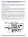
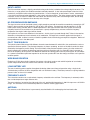
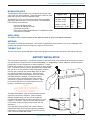
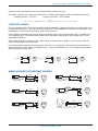
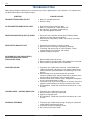
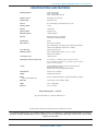
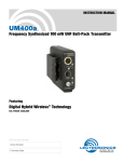
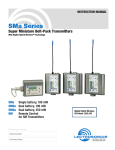
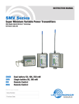
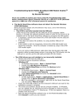
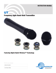
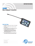
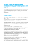
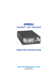
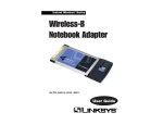
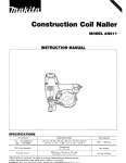
LM
FREQUENCY-AGILE UHF
BELT-PACK TRANSMITTER
Featuring Digital Hybrid Wireless™ Technology
(US Patent Pending)
OPERATING INSTRUCTIONS
LECTROSONICS, INC.
Rio Rancho, NM, USA
www.lectrosonics.com
LM
2
LECTROSONICS, INC.
Frequency Agile UHF Belt-Pack Transmitter
Thank you for selecting the Lectrosonics LM frequency agile, belt-pack transmitter.
The design of the LM introduces the advanced technology and features of a classic Lectrosonics beltpack transmitter at a moderate cost. The unit is designed around the Digital Hybrid WirelessTM
system (US Patent Pending) which combines a digital audio chain with an analog FM radio link. This
digital process eliminates the compandor and it’s problems, yet preserves the extended operating
range of the finest analog wireless systems.
The LM also preserves your investment. The transmitter can emulate the compandor found in 100,
200 and IFB Series Lectrosonics receivers, and certain receivers from other manufacturers. (Call
Lectrosonics for more details.) Changing the compatibility mode is accomplished with a simple
procedure that does not require opening the unit.
The mechanical assembly is a rugged, machined aluminum package with a removable, stainless steel
wire belt clip. The input jack is a standard Lectrosonics 5-pin type for use with electret lavalier mics,
dynamic mics and line level signals. LEDs are provided on the LM front panel to make quick and
accurate level settings without having to view the receiver. The battery compartment accepts any 9
volt battery (alkaline or lithium recommended) and makes a positive connection via self-adjusting
contacts. The antenna is a super-rugged, permanently attached 1/4 wavelength design made of
flexible galvanized steel cable.
Only the LM transmitter is covered in this manual. Companion receivers are covered in separate
manuals.
TABLE OF CONTENTS
GENERAL TECHNICAL DESCRIPTION .......................................................................... 4
INTRODUCTION ........................................................................................................... 4
DIGITAL HYBRID TECHNOLOGY ................................................................................ 4
INPUT LIMITER ............................................................................................................ 5
NO PRE-EMPHASIS/DE-EMPHASIS ........................................................................... 5
PILOT TONE SQUELCH .............................................................................................. 5
WIDE-BAND DEVIATION .............................................................................................. 5
LONG BATTERY LIFE ................................................................................................... 5
FREQUENCY AGILITY ................................................................................................. 5
ANTENNA ..................................................................................................................... 5
CONTROLS AND FUNCTIONS ........................................................................................ 6
MIC ................................................................................................................................ 6
POWER ON/OFF SWITCH ........................................................................................... 6
POWER LED ................................................................................................................. 6
FREQUENCY SELECT SWITCHES ............................................................................. 6
MODULATION LEDS .................................................................................................... 7
AUDIO LEVEL ............................................................................................................... 7
ANTENNA ..................................................................................................................... 7
THE BELT CLIP ............................................................................................................. 7
BATTERY INSTALLATION ................................................................................................. 7
OPERATING INSTRUCTIONS .......................................................................................... 8
SELECTING COMPATIBILITY MODE .......................................................................... 8
ATTACHING A MICROPHONE AND ADJUSTING AUDIO LEVELS ............................ 8
OPERATING NOTES ......................................................................................................... 9
ADJUSTING THE TRANSMITTER FREQUENCY ........................................................... 9
5-PIN INPUT JACK WIRING ........................................................................................... 10
RF BYPASSING .......................................................................................................... 10
LINE LEVEL SIGNALS ................................................................................................ 11
WIRING HOOKUPS FOR DIFFERENT SOURCES ................................................... 11
TROUBLESHOOTING ..................................................................................................... 12
SPECIFICATIONS AND FEATURES .............................................................................. 13
SERVICE AND REPAIR .................................................................................................. 14
RETURNING UNITS FOR REPAIR ................................................................................ 14
LIMITED ONE YEAR WARRANTY ................................................................................. 16
The LM transmitter is FCC type accepted under Part 74: 536-608 MHz and 614-806 MHz
Rio Rancho, NM – USA
3
LM
GENERAL TECHNICAL DESCRIPTION
INTRODUCTION
The Digital Hybrid Wireless™ system uses 75 kHz wide deviation for an extremely high signal to noise ratio. The
switching power supplies provide constant voltages to the transmitter circuits from the beginning (9.3 VDC) to the
end (5.5 VDC) of battery life. The input amplifier uses an ultra low noise operational amplifier (op amp) for quiet
operation. It is gain controlled with a wide range dual envelope input limiter that tames input signal peaks over 30 dB
above full modulation.
DIGITAL HYBRID TECHNOLOGY
All wireless links suffer from channel noise to some degree, and all wireless microphone systems seek to minimize
the impact of that noise on the desired signal. Conventional analog systems use compandors for enhanced dynamic
range, at the cost of subtle artifacts (known as “pumping” and “breathing”). Wholly digital systems defeat the noise
by sending the audio information in digital form, at the cost of some combination of power, bandwidth, operating
range and resistance to interference.
The Lectrosonics Digital Hybrid Wireless™ system overcomes channel noise in a dramatically new way, digitally
encoding the audio in the transmitter and decoding it in the receiver, yet still sending the encoded information via an
analog FM wireless link. This proprietary algorithm is not a digital implementation of an analog compandor but a
technique which can be accomplished only in the digital domain. (The patent is still pending, so we cannot publish
detailed information).
Channel noise still has an impact on received signal quality and will eventually overwhelm the receiver. The Digital
Hybrid Wireless™ system simply encodes the signal to use a noisy channel as efficiently and robustly as possible,
yielding audio performance that rivals that of wholly digital systems, without the power, noise and bandwidth problems inherent in digital transmission. As always, these advantages come at a cost. The Digital Hybrid Wireless™
system requires fairly intensive digital processing in both the transmitter and the receiver. These processors cost
money, take up space and consume power. The Digital Hybrid WirelessTM system also requires that the underlying
RF link be of excellent quality, with better frequency response and distortion characteristics than that required by
conventional analog wireless systems.
Because it uses an analog FM link, Digital Hybrid Wireless™ enjoys all the benefits of conventional FM wireless
systems, such as excellent range, efficient use of RF spectrum, and long battery life. However, unlike conventional
FM systems, Digital Hybrid Wireless™ has done away with the analog compandor and its artifacts.
Mic
Jack
1
2
3
4
5
+5V Bias<--See
Supply
Hi/Lo
Pass
Filter
5-Pin Input Jack Wiring for details.
Audio
Input
Amp
Audio
Level
A-D
Converter
D-A
Converter
11001001
11001001
Encoded
Audio +
Pilot Tone
Digital Signal Processor
9V
Battery
Shunt
Limiter
Bicolor
Power
LED
Microprocessor
Bicolor
Modulation
LEDs
Freq
Switches
Phase Locked Loop
Voltage
Controlled
Oscillator
11.3 MHz
Reference
LM Block Diagram
4
Switching
Power
Supply
LECTROSONICS, INC.
Final
Amplifier
+3.3v
+1.8v
+9v
-3v
Frequency Agile UHF Belt-Pack Transmitter
INPUT LIMITER
The LM transmitter employs a digitally-controlled analog audio limiter just before the analog-to-digital converter. The
limiter has a range greater than 30 dB for excellent overload protection. A dual release envelope makes the limiter
acoustically transparent while maintaining low distortion. It can be thought of as two limiters in series, connected as
a fast attack and release limiter followed by a slow attack and release limiter. The limiter recovers quickly from brief
transients, so that its action is hidden from the listener, but recovers slowly from sustained high levels, to both keep
audio distortion low and preserve short term dynamic changes.
NO PRE-EMPHASIS/DE-EMPHASIS
The signal to noise ratio of the hybrid system is high enough to preclude the need for conventional pre-emphasis (HF
boost) in the transmitter and de-emphasis (HF roll off) in the receiver. Pre-emphasis and de-emphasis in an FM
radio system usually provides about a 10 dB improvement in the signal to noise ratio of the system, but the high
frequency boost in the transmitter must be removed in a purely complementary manner or else the frequency
response of the original audio signal will be altered.
Pre-emphasis can also cause distortion in the receiver. As this signal is passed through the IF filters in the receiver,
distortion can be produced, most noticeably at full modulation. De-emphasis cannot be applied until the signal is
converted into audio, so there is no way around this problem short of eliminating pre-emphasis altogether. Neither of
these problems occur in the 400 system
PILOT TONE SQUELCH
The hybrid system utilizes one of 256 different ultrasonic tones between 25 and 32 kHz, that modulate the carrier to
operate the receiver squelch. The pilot tone frequency is chosen according to which of the 256 channels has been
selected by the frequency switch setting. The basic benefit of the pilot tone squelch system is that the receiver will
remain muted until it receives the pilot tone from the matching transmitter, even if a strong RF signal is present on
the carrier frequency of the system. The 400 Series extends this concept even further by insuring that all transmitters
in a system have different pilot tone frequencies so that even spurious RF from the wrong transmitters can’t open the
receiver squelch.
WIDE-BAND DEVIATION
Employing ±75 kHz dramatically improves the capture ratio, signal to noise ratio and AM rejection of our wireless
system compared to those that use the more common ±15 kHz deviation.
LONG BATTERY LIFE
The use of switching power supplies throughout the design allow over 6 hours of operation using a single 9 volt
alkaline battery and over 13 hours of operation with a 9 volt lithium battery. The battery contacts are spring loaded to
prevent “rattle” as the unit is handled.
FREQUENCY AGILITY
The transmitter section uses a synthesized, frequency selectable main oscillator. The frequency is extremely stable
over a wide temperature range and over time.
Two rotary switches, located on the side panel of the unit, provide 256 frequencies in 100 kHz steps over a 25.5 MHz
range. This alleviates carrier interference problems in mobile or traveling applications.
ANTENNA
The antenna on the LM consists of a permanently attached flexible 1/4 wavelength galvanized steel cable.
Rio Rancho, NM – USA
5
LM
CONTROLS AND FUNCTIONS
Belt Cip
MIC input jack
Battery
Compartment Door
AUDIO LEVEL
control
Modulation LEDs
Power ON/OFF
Power LED
Antenna
Frequency Select
Switches
Belt Cip
Attachment Holes
MIC
The input accommodates virtually every lavaliere, hand-held or shotgun microphone available. Line level signals can
also be accommodated. Use a Switchcraft TA5F connector on the cord. (See 5-Pin Input Jack Wiring.)
POWER ON/OFF SWITCH
Turns the transmitter on and off. A pilot tone muting system prevents “thumps” or transients from occurring even if
the transmitter is abruptly switched on or off.
POWER LED
Glows green when the LM transmitter is operating and the battery is good. Turns red when the battery voltage drops
to 6.1 VDC. Starts blinking red when the voltage is to 5.6 VDC. When using a recommended lithium or alkaline
battery, there will be about 30 minutes of operating time remaining when the Power LED first begins blinking red.
Note
A weak battery will sometimes cause the Power LED glow green, but it will soon discharge to the
point where the Power LED will glow red or go out completely. If in doubt, replace the battery
with a known new battery prior to starting the program. If the Power LED fails to glow when the
LM is turned on, replace the battery.
A NiMH batteries give little or no warning when they are depleted. If you wish to use NiMH batteries in the LM
transmitter, you will need to manually keep track of the operating time. Start with a fully charged battery, then
measure the time it takes for the Power LED to extinguish. A number of Lectrosonics receivers incorporate a Battery
Timer function which track the amount of time the transmitter signal is detected (See your receiver manual to
determine is this function is available.) By using the receiver’s battery timer and replacing the transmitter battery
before the premeasured time is up, users can minimize potential loss of audio when NiMH batteries are used.
FREQUENCY SELECT SWITCHES
Two 16-position rotary Frequency Select Switches accessed through the side panel are used to adjust the center
frequency of the carrier signal. These switches are labeled 1.6M and 100K. The 1.6M switch is used for coarse
frequency adjustments and the 100K is used for fine frequency adjustment
6
LECTROSONICS, INC.
Frequency Agile UHF Belt-Pack Transmitter
MODULATION LEDS
The Modulation LEDs provide a visual indication of the input audio
signal level from the microphone. These two bicolor LEDs can glow
either red or green to indicate modulation levels.
The Modulation LEDs are also used to indicate the Compatibility
Mode when the transmitter is initially turned on. The Modulation
LEDs will blink simultaneously:
• Once for 100 Series mode
• Two times for 200 Series mode
• Three times for mode 3
• Four times for Digital Hybrid Wireless™ or 400 Series mode
• Five times for IFB mode
Signal Level
Less than -20 dB
-20 dB to -10 dB
-10 dB to +0 dB
+0 dB to +10 dB
Greater than +10 dB
-20 LED -10 LED
Off
Green
Green
Red
Red
Off
Off
Green
Green
Red
AUDIO LEVEL
The AUDIO LEVEL control is used to set the audio input level (or gain) for the proper modulation.
ANTENNA
The flexible, insulated galvanized steel cable antenna supplied with the transmitter is cut to 1/4 wavelength of the
center of the frequency block (the frequency range) of the transmitter.
THE BELT CLIP
The belt clip may be removed for special applications by pulling the ends out of the holes in the sides of the case.
BATTERY INSTALLATION
The transmitter is powered by a standard 9 volt battery. We recommend using alkaline or lithium battery for longest
life. Standard zinc-carbon batteries marked “heavy-duty” or “long-lasting” are not adequate. Alkaline batteries
provide over six hours of operation at room temperature. Lithium
batteries can provide up to 13 hours and will work at lower temperatures. The battery status circuitry is designed for the voltage drop
over the life of alkaline batteries. NiMH rechargeable batteries
will also work; although they provide fewer hours of operation and will run down quite abruptly. Because of this,
using the Power LED to verify battery status not reliable
with NiMH batteries; although, it may be possible to
track battery status using the Battery Timer function
available in a number of Lectrosonics receivers. (Refer
to the associated receiver manual to determine is this
function is available in your situation.)
1
Warning
Care should be taken not to leave a fully
discharged lithium battery in the transmitter, as
swelling of the battery can make it difficult to
remove from the compartment.
To replace the batteries, push up on the Battery Compartment Door and rotate it clockwise. (See illustration.)
Remove the old battery and take note of the polarity
marked inside showing the location of the positive (+) and
negative (-) terminals. (You can see the large and small
contact holes inside the battery compartment with the
door open.)
2
Insert the new battery correctly and close the Battery
Compartment Door by reversing the opening procedure.
If the battery is inserted incorrectly, the door will not fully
close. Do not force the door closed.
Rio Rancho, NM – USA
7
LM
OPERATING INSTRUCTIONS
SELECTING COMPATIBILITY MODE
The LM transmitter is based on Digital Hybrid Wireless™ technology, but is also capable of working with Lectrosonics
200, 100 and IFB series analog receivers and with some other analog wireless receivers (contact the factory for
details). The transmitter compatibility mode must be set to match receiver for the system to operate properly. Setting the transmitter’s operating mode is easily accomplished using only a small screwdriver. One is supplied with the
transmitter.
Note
The unit is supplied from the factory as a 400 series transmitter
1) Ensure the battery is good and installed properly by setting the LM’s Power ON/
OFF switch to ON and verifying the Power LED glows green, then set the Power
ON/OFF switch to OFF.
Modulation
LEDS
2) Verify the current compatibility mode by setting the Power ON/OFF switch to ON
and observing the front panel Modulation LEDs. The –20 and –10 LEDs will blink
simultaneously:
• Once for 100 Series mode
• Two times for 200 Series mode
• Three times for mode 3
• Four times for Digital Hybrid Wireless™ or 400 Series mode
• Five times for IFB mode
Power ON/OFF
switch
Power LED
3) To change the compatibility mode, set the Power ON/OFF
switch to OFF and, using a small screwdriver, set both
Frequency Select Switches to “C.” (for Change, Change).
4) Briefly power up the unit – just long enough for the front
panel LEDs to light up, and then turn the unit off.
5) Change the Frequency Select Switch settings to one of
the following positions:
• Lectrosonics 100 Series mode:
• Lectrosonics 200 Series mode:
• mode 3 (contact the factory for details):
• Digital Hybrid Wireless™ (400 Series) mode:
• IFB mode:
1,1
2,2
3,3
4,4
5,5
6) Turn on the transmitter, wait until the front panel LEDs
glow, then turn it off again.
E
D
C
B
A
F 0 1
2
3
4
5
9 8 7
1.6M
6
E
D
C
B
A
F 0 1
2
3
4
5
9 8 7
6
100K
Frequency Select Switch
Settings (C,C)
7) Change the Frequency Select Switch settings to 0,0.
8) Turn on the transmitter top verify the compatibility mode for the unit has changed.
Note
Each time the transmitter is turned on, it will confirm the current operating mode with the number of blinks listed in
Step 2. The mode setting will remain the same until you reset it with the procedure listed above.
ATTACHING A MICROPHONE AND ADJUSTING AUDIO LEVELS
The front panel Modulation LEDs indicate limiter activity. (See chart.) At -20 dB, the -20 LED glows green. At -10
dB, both the -20 and the -10 LEDs glow green. At 0 dB, the -20
LED glows red and the -10 LED glows green, and at +10 dB, both
Signal Level
-20 LED -10 LED
LEDs glow red. Since the distortion introduced by the limiter is
minimal and full modulation is assured, occasional forays into the
Off
Less than -20 dB
Off
red by the -10 LED is acceptable.
Off
-20 dB to -10 dB
Green
1) If necessary, install a fresh battery.
Green
-10 dB to +0 dB
Green
2) Insert the microphone plug into the MIC input jack. Ensure
Green
+0 dB to +10 dB
Red
the pins are aligned and the connector locks in (it will click).
Red
Greater than +10 dB Red
3) Mute the main sound system and rotate the AUDIO LEVEL
control on the LM transmitter to maximum counterclockwise
(Off).
8
LECTROSONICS, INC.
Frequency Agile UHF Belt-Pack Transmitter
4) Set the transmitter Power ON/OFF switch to ON.
MIC input jack
5) Position the microphone in the location where it will be used in actual operation.
AUDIO
LEVEL control
6) Observe the Modulation LEDS while speaking or singing at the same voice
level that will be used during the program. Gradually rotate the AUDIO
LEVEL control clockwise until the -20 LED glows red and the -10 dB glows
green with occasional red flickers. This indicates full modulation and is the -10 LED
optimum setting for the transmitter’s gain.
-20 LED
7) Once the LM’s audio gain has been set, the remaining components of the
audio system can be energized and adjusted.
OPERATING NOTES
DO NOT USE THE AUDIO LEVEL control for controlling the volume of your sound system or recorder levels. This
gain adjustment matches the transmitter gain with the user’s voice level and microphone positioning.
If the audio level is too high — the -20 LED will glow red and the -10 LED will frequently blink or glow
steady red. This condition may reduce the dynamic range of the audio signal.
If the audio level is too low — neither LED will light, or only the -20 LED will blink or glow green. This
condition may cause hiss and noise in the audio.
Different voices will usually require different settings of the AUDIO LEVEL control, so check this adjustment as each
new person uses the system. If several different people will be using the transmitter and there is not time to make
the adjustment for each individual, adjust it for the loudest voice.
ADJUSTING THE TRANSMITTER FREQUENCY
If you are experiencing interference from another signal on your operating frequency, you may need to change the
operating frequency of your system. This is done through two Frequency Select Switches located on the left side of
the transmitter case. (See Frequency Select Switch Locations.)
The left switch increments the operating frequency in 1.6 MHz steps. The right switch increments the operating
frequency in 100 kHz steps. It is suggested to use the metering on the associated receiver to find a clear channel.
Turn the transmitter off and leave the receiver turned on. Tune the receiver across its band and find a frequency
where little or no RF activity is displayed. Set the transmitter to this new frequency, then turn it on and make sure the
RF signal is strongly indicated at the receiver. Be sure the switch settings between the receiver and transmitter are
set exactly the same. If, for example, the 100K switch is one click above or below the desired frequency, the receiver
will indicate RF but no audio (or severely distorted audio) will be produced.
All 400 Series (and a number of earlier receivers) offer
a front panel LCDs that indicate the correct transmitter
switch settings when locating clear channels. Use the
scanning functions on these receivers to find a clear
channel, then switch both the receiver and transmitter
to the Frequency Select Switch settings indicated in
the receiver’s display.
E
D
C
B
A
F 0 1
2
3
4
5
9 8 7
6
1.6M
E
D
C
B
A
F 0 1
2
3
4
5
9 8 7
6
100K
Frequency Select Switch Locations
Rio Rancho, NM – USA
9
LM
5-PIN INPUT JACK WIRING
The wiring diagrams shown in Wiring Hookups For Different Sources represent the basic wiring configurations
necessary for the most common types of microphones and other audio inputs. Some microphones may require extra
jumpers or a slight variation in the diagrams shown.
It’s virtually impossible to keep completely up to date on changes that other manufacturers make to their products. It
is possible that you may encounter a microphone that differs from those illustrated. If this occurs please call our tollfree number listed in the back of this manual for assistance. Our Service Department can answer your questions
regarding microphone compatibility.
When used on a wireless transmitter, the microphone element is in the proximity of the RF coming from the transmitter. The nature of electret microphones makes them sensitive to RF, which can cause problems with the microphone/
transmitter compatibility. If the electret microphone is not designed properly for use with wireless transmitters, it may
be necessary to install a chip capacitor in the mic capsule or connector to block the RF from entering the electret
capsule. (See RF Bypassing.)
LECTROSONICS
4
5
1
3
2
1
NEG GND (OR BIAS)
2
POS BIAS (OR GND)
3
MIC
4
SOURCE LOAD
5
LINE IN
1k
FB
+
330pF
100
5V Mic Bias
10uF
+
To Mic Amp
330pF
4k
330pF
40k
330pF
LM Front Panel
Input Jack
Input Circuit
PIN 1
Shield (ground) for positive biased electret lavalliere microphones. For the increasingly
rare negative biased electret lavalliere microphones, it is the bias voltage source. It is
also the shield (ground) for dynamic microphones and line level inputs.
PIN 2
Shield (ground) for negative biased electret lavalliere microphones. Bias voltage source
for positive biased electret lavalliere microphones.
PIN 3
Low impedance microphone level input for dynamic microphones. Also accepts handheld electret microphones that have their own battery or power supply.
PIN 4
4 k Ohm source load for non-Lectrosonics electret microphones. Use in conjunction with
other pins to provide attenuation of high level input signals.
PIN 5
40 k high impedance, line level input for tape decks, mixer outputs, musical instruments,
etc.
RF BYPASSING
Some mics require RF protection to keep the transmitter signal from affecting the capsule, even though the
transmitter input circuitry is already RF bypassed (see
5-Pin Input Jack Wiring schematic diagram above).
2 WIRE MIC
Preferred locations for bypass capacitors
If the mic is wired as directed, and you are having
difficulty with squealing, high noise, or poor frequency
response, RF is likely to be the cause.
The best RF protection is accomplished by installing
330 pF bypass capacitors at the mic capsule. If this is
not possible, or if you are still having problems,
3 WIRE MIC
SHIELD
SHIELD
AUDIO
AUDIO
BIAS
CAPSULE
TA5F
CONNECTOR
CAPSULE
Alternate locations for bypass capacitors
10
LECTROSONICS, INC.
TA5F
CONNECTOR
Frequency Agile UHF Belt-Pack Transmitter
capacitors can be installed on the mic wires inside the TA5F connector housing.
The 330 pF capacitors are available from Lectrosonics. Please specify the part number for the desired lead style.
Leaded capacitors: P/N 15117
Leadless capacitors: P/N SCC330P
Note
The Lectrosonics M150 lavalliere mic is already bypassed correctly for use with the LM.
LINE LEVEL SIGNALS
The normal hookup for line level signals provides 40 dB of attenuation allowing signal levels much higher than 3 V to
be applied without limiting. The normal hookup configuration can be modified for situations that require higher levels
of headroom, or lower levels of attenuation. (See illustration below.)
Normal hookup configuration connects the Signal Hot (Audio) to pin 5, Signal Gnd (Shield) to pin 1, and both pins 3
and 4 jumped to pin 1. This configuration provides 40 dB attenuation allowing signal levels greater than 3 V to be
applied without limiting.
If even more headroom is required, insert a 100 k resistor in series with pin 5 (Audio). Put this resistor inside the
TA5F connector to minimize noise pickup.
For situations where lower than normal line levels (less than 1 V) are expected, use the Lower Line Level Hook Up:
Signal Hot (Audio) to pin 5, Signal Gnd (Shield) to pin 1, and pin 4 jumpered to pin 1. This configuration provides 20
dB attenuation to the input signal.
SHIELD (GND)
Normal Hookup
PIN
1
2
3
AUDIO
4
5
SHIELD (GND)
4
3
5
1
2
More Headroom
PIN
1
2
3
100k
TA5F
PLUG
AUDIO
4
5
SHIELD (GND)
4
3
5
1
2
PIN
Lower Line Level
Hookup
TA5F
PLUG
1
2
3
4
5
AUDIO
4
3
5
1
2
TA5F
PLUG
WIRING HOOKUPS FOR DIFFERENT SOURCES
PIN
SHIELD
BIAS
3 WIRE ELECTRET MIC
POSITIVE BIAS
PIN
1
2
3
AUDIO
4
5
SHIELD
4
3
5
1
2
TA5F
PLUG
2 WIRE ELECTRET MIC
NEGATIVE BIAS
SHIELD
2 WIRE ELECTRET MIC
POSITIVE BIAS
SHIELD
1
2
AUDIO
3
4
5
4
3
5
1
2
TA5F
PLUG
3
4
5
PIN
BIAS
3 WIRE ELECTRET MIC
NEGATIVE BIAS
AUDIO
1
2
3
4
5
2
LINE LEVEL
RCA or 1/4 " PLUG
1
3
4
3
5
1
2
TA5F
PLUG
DYNAMIC
MIC LEVEL
Rio Rancho, NM – USA
1
2
SHIELD
5
1
2
TA5F
PLUG
1
TIP
2
4
3
PIN
AUDIO
PIN
SHIELD
3
4
5
SLEEVE
PIN
1
2
AUDIO
4
3
5
1
2
TA5F
PLUG
PIN
1
2
3
3
Dynamic LO Z mic or electret with
manufacturer’s power supply.
4
5
4
3
5
1
2
TA5F
PLUG
11
LM
TROUBLESHOOTING
Before going through the following chart, ensure that you have a good battery in the transmitter. It is important that
you follow these steps in the sequence listed.
SYMPTOM
POSSIBLE CAUSE
TRANSMITTER BATTERY LED OFF
1. Battery is inserted backwards.
2. Battery is dead.
NO TRANSMITTER MODULATION LEDs
1.
2.
3.
4.
RECEIVER INDICATES RF BUT NO AUDIO
1. Ensure that the transmitter and receiver Frequency Select
Switches are set to the same frequency.
2. Make sure the compatibility mode is the same on transmitter
and receiver.
RECEIVER RF INDICATOR OFF
1. Transmitter not turned on, or battery is dead.
3. Receiver antenna missing or improperly positioned.
4. Transmitter and receiver not on same frequency. Check
switches/display on transmitter and receiver.
5. Operating range is too great.
NO SOUND (OR LOW SOUND LEVEL),
RECEIVER INDICATES PROPER
AUDIO MODULATION
Gain control turned all the way down.
Battery is in backwards. Check power LED.
Mic capsule is damaged or malfunctioning.
Mic cable damaged or miswired.
1. Receiver output level set too low.
2. Receiver output is disconnected; cable is defective or miswired.
3. Sound system or recorder input is turned down.
DISTORTED SOUND
1. Transmitter gain (audio level) is too high. Check Modulation
LEDs on transmitter and receiver as transmitter is being used.
(Refer to Attaching and Microphone and Adjusting Gain in this
manual.)
2. Receiver output may be mismatched with the sound
system or recorder input. Adjust output level on receiver to the
correct level for the recorder, mixer or sound system.
3. Excessive wind noise or breath “pops.” Reposition microphone,
or use a larger windscreen, or both.
4. Transmitter is not set to same frequency as receiver. Check that
frequency select switches on receiver and transmitter match.
5. RF interference. Reset both transmitter and receiver to a clear
channel.
HISS AND NOISE -- AUDIBLE DROPOUTS
1.
2.
3.
4.
EXCESSIVE FEEDBACK
1. Transmitter gain (audio level) too high. Check gain adjustment
and/or reduce receiver output level.
2. Transmitter too close to speaker system.
3. Mic is too far from user’s mouth.
12
Transmitter gain (audio level) far too low.
Receiver antenna missing or obstructed.
Operating range too great.
RF interference. Reset both transmitter and receiver to a clear
channel.
LECTROSONICS, INC.
Frequency Agile UHF Belt-Pack Transmitter
SPECIFICATIONS AND FEATURES
Operating frequencies:
537.600 to 607.900 MHz
614.100 to 767.900 MHz
768.000 to 805.600 MHz (export only)
Frequency selection:
256 frequencies in 100 kHz steps
RF Power output:
Greater than 50 mW
Pilot tone:
25 to 32 kHz frequency; 5 kHz deviation (400 Series only)
Frequency stability:
± 0.002%
Deviation:
± 75 kHz (max)
Spurious radiation:
60 dB below carrier
Equivalent input noise:
–120 dBV, A-weighted
Input level:
Nominal 2 mV to 300 mV, before limiting.
Greater than 1V maximum, with limiting.
Input impedance:
2k Ohm
Input compressor:
Dual envelope, >30 dB range
(Note: The dual envelope “soft” limiter provides exceptionally good handling of
transients using variable attack and release time constraints.)
Gain control range:
43 dB; semi-log rotary control
Modulation indicators:
Dual bicolor LEDs indicate modulation of -20, -10, 0, +10 dB
referenced to full modulation.
Low frequency roll-off:
–12 dB/octave; 70Hz
Audio frequency response (overall system):
90 Hz to 20 kHz (+/- 1 dB) with the 70Hz low frequency roll-off filter.
(Note: The transmitter is deliberately rolled off at 70Hz to reduce the undesired
effects of the lower frequencies.)
Controls:
2 position “OFF-ON” slide switch for noiseless turn on/turn off operation.
Front panel knob adjusts audio gain.
Rotary switches on side panel adjust transmitter frequency.
Audio Input Jack:
Switchcraft 5 pin locking (TA5F)
Antenna:
Galvanized steel, flexible wire.
Battery:
(We’ve tried 243 different ones!)
Precision compartment auto-adjusts to accept any known alkaline 9 volt battery.
Battery Life:
6 hours (alkaline); 13 hours continuous (lithium)
Weight:
6.3 ozs. including battery
Dimensions:
3.1 x 2.4 x .75 inches
Emission Designator: 180KF3E
Specifications subject to change without notice.
The FCC requires that the following statement be included in this manual:
This device complies with FCC radiation exposure limits as set forth for an uncontrolled environment. This device
should be installed and operated so that its antenna(s) are not co-located or operating in conjunction with any other
antenna or transmitter.
Rio Rancho, NM – USA
13
LM
SERVICE AND REPAIR
If your system malfunctions, you should attempt to correct or isolate the trouble before concluding that the equipment
needs repair. Make sure you have followed the setup procedure and operating instructions. Check out the interconnecting cords and then go through the TROUBLESHOOTING section in the manual
We strongly recommend that you do not try to repair the equipment yourself and do not have the local repair shop
attempt anything other than the simplest repair. If the repair is more complicated than a broken wire or loose connection, send the unit to the factory for repair and service. Don’t attempt to adjust any controls inside the units.
Once set at the factory, the various controls and trimmers do not drift with age or vibration and never require readjustment. There are no adjustments inside that will make a malfunctioning unit start working.
The LECTROSONICS Service Department is equipped and staffed to quickly repair your equipment. In-warranty
repairs are made at no charge in accordance with the terms of the warranty. Out-of-warranty repairs are charged at
a modest flat rate plus parts and shipping. Since it takes almost as much time and effort to determine what is wrong
as it does to make the repair, there is a charge for an exact quotation. We will be happy to quote approximate
charges by phone for out-of-warranty repairs.
RETURNING UNITS FOR REPAIR
You will save yourself time and trouble if you will follow the steps below:
A. DO NOT return equipment to the factory for repair without first contacting us by letter or by phone. We
need to know the nature of the problem, the model number and the serial number of the equipment. We
also need a phone number where you can be reached 8 a.m. to 4 p.m. (U.S.-Mountain Standard Time).
B. After receiving your request, we will issue you a return authorization number (R.A.). This number will help
speed your repair through our receiving and repair departments. The return authorization number must be
clearly shown on the outside of the shipping container.
C. Pack the equipment carefully and ship to us, shipping costs prepaid. If necessary, we can provide you with
the proper packing materials. UPS is usually the best way to ship the units. Heavy units should be
“double-boxed” for safe transport.
D. We also strongly recommend that you insure the equipment, since we cannot be responsible for loss of or
damage to equipment that you ship. Of course, we insure the equipment when we ship it back to you.
Mailing address:
Lectrosonics, Inc.
PO Box 15900
Rio Rancho, NM 87174
USA
Shipping address:
Lectrosonics, Inc.
581 Laser Rd.
Rio Rancho, NM 87124
USA
Web: http://www.lectrosonics.com
14
Telephones:
Regular: (505) 892-4501
Toll Free (800) 821-1121
FAX:
(505) 892-6243
Email: [email protected]
LECTROSONICS, INC.
Frequency Agile UHF Belt-Pack Transmitter
Rio Rancho, NM – USA
15
LIMITED
WARRANTY
LIMITEDONE
ONE YEAR
YEAR WARRANTY
The equipment is warranted for one year from date of purchase against defects in
materials or workmanship provided it was purchased from an authorized dealer. This
warranty does not cover equipment which has been abused or damaged by careless
handling or shipping. This warranty does not apply to used or demonstrator equipment.
Should any defect develop, Lectrosonics, Inc. will, at our option, repair or replace any
defective parts without charge for either parts or labor. If Lectrosonics, Inc. cannot
correct the defect in your equipment, it will be replaced at no charge with a similar new
item. Lectrosonics, Inc. will pay for the cost of returning your equipment to you.
This warranty applies only to items returned to Lectrosonics, Inc. or an authorized
dealer, shipping costs prepaid, within one year from the date of purchase.
This Limited Warranty is governed by the laws of the State of New Mexico. It states the
entire liablility of Lectrosonics Inc. and the entire remedy of the purchaser for any
breach of warranty as outlined above. NEITHER LECTROSONICS, INC. NOR
ANYONE INVOLVED IN THE PRODUCTION OR DELIVERY OF THE EQUIPMENT
SHALL BE LIABLE FOR ANY INDIRECT, SPECIAL, PUNITIVE, CONSEQUENTIAL,
OR INCIDENTAL DAMAGES ARISING OUT OF THE USE OR INABILITY TO USE
THIS EQUIPMENT EVEN IF LECTROSONICS, INC. HAS BEEN ADVISED OF THE
POSSIBILITY OF SUCH DAMAGES. IN NO EVENT SHALL THE LIABILITY OF
LECTROSONICS, INC. EXCEED THE PURCHASE PRICE OF ANY DEFECTIVE
EQUIPMENT.
This warranty gives you specific legal rights. You may have additional legal rights which
vary from state to state.
LECTROSONICS, INC.
581 LASER ROAD
RIO RANCHO, NM 87124 USA
www.lectrosonics.com
LMMAN-0504