1
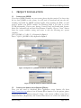
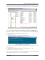
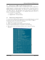
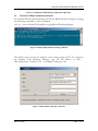
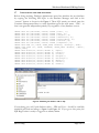
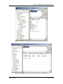
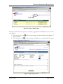
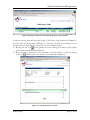
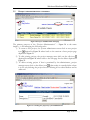
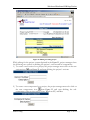
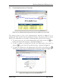
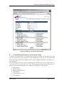
Web-based Distributed EJB BugsTracker
ROCHESTER INSTITUTE OF TECHNOLOGY
Department of Computer Science
User Manual
Web-based Distributed EJB BugsTracker
An integration of Struts Framework at Web Server, EJBs at Application Server, and a
Relational Database
San Htun Aung
[email protected]
September 26, 2003
Committee Members
Advisor: Dr. Fereydoun Kazemian
Reader: Dr. Rajendra K. Raj
Observer: Dr. Sidney Marshall
San H. Aung
Page 1 of 21
Web-based Distributed EJB BugsTracker
TABLE OF CONTENTS:
FIGURES:..................................................................................................................................................... 3
1.
PROJECT INSTALLATION ............................................................................................................ 4
1.1
1.2
1.3
1.4
1.5
1.6
1.7
INSTALLING J2SDK: .................................................................................................................... 4
INSTALLING APPLICATION SERVER (JBOSS): ............................................................................... 4
RUNNING INTEGRATED SERVER (TOMCAT, JBOSS, AND HSQL DB):........................................... 5
DEPLOYMENT OF EJBS AND WEB SERVER COMPONENTS: ........................................................... 6
VERIFICATION OF DEPLOYMENT: ................................................................................................. 6
RUNNING HSQL DATBASE MANAGER: ......................................................................................... 7
INITIALIZING THE NEW DATABASE: .............................................................................................. 8
2.
OVERALL SITE MAP..................................................................................................................... 10
3.
USER MANUAL............................................................................................................................... 11
3.1
3.2
3.3
3.4
3.5
3.6
3.7
3.8
LOGGED-IN PAGE ........................................................................................................................ 11
WELCOME PAGE ........................................................................................................................ 11
HOME PAGE CATEGORY ............................................................................................................. 12
PROJECT LIST CATEGORY: ......................................................................................................... 13
PROJECT ADMINISTRATION CATEGORY: ..................................................................................... 16
USER ADMINISTRATION CATEGORY: ......................................................................................... 18
USER PERMISSIONS (APPLY TO NON-SUPER USER): ..................................................................... 19
DEFINITION OF THE DEFECT’S STATUS ........................................................................................ 21
San H. Aung
Page 2 of 21
Web-based Distributed EJB BugsTracker
FIGURES:
Figure 1: Setup the JAVA_HOME environment variables in Windows 2000 ················································ 4
Figure 2: Setup the Path environment in Windows 2000 ··············································································· 4
Figure 3: Directories structure of JBoss is on the left and the deployment files are on the right. ················· 5
Figure 4: Run JBoss server in Windows 2000································································································ 5
Figure 5: Completion of EJBs and Web components deployment.································································· 7
Figure 6: Running HSQL Database Manager (Default) ················································································ 7
Figure 7: HSQL Database manager connection login.·················································································· 7
Figure 8: Initializing the database with six SQL.··························································································· 8
Figure 9: Validating “IDs” table for generating independent primary keys ················································· 9
Figure 10: Validating “User” table for the first super user – admin/admin.················································· 9
Figure 11: All access paths for each screen································································································· 10
Figure 12: login page··································································································································· 11
Figure 13: Welcome page right after user login. ························································································· 11
Figure 14: Currently login user’s Home page ····························································································· 12
Figure 15: Editing defects ···························································································································· 13
Figure 16: Project’s summary page············································································································· 14
Figure 17: Reporting new defect ·················································································································· 14
Figure 18: listing of all defects associated with the given project (Kodak) ················································· 15
Figure 19: Viewing the defect’s contents ····································································································· 15
Figure 20: Project Administration main page······························································································ 16
Figure 21: Creating new project by system administrator··········································································· 16
Figure 22: Editing of existing project. ········································································································· 17
Figure 23: User administration main page where list all available users to the system······························ 18
Figure 24: Creating a new user by the administrator ·················································································· 18
Figure 25: Editing user permissions and its profiles ··················································································· 19
San H. Aung
Page 3 of 21
Web-based Distributed EJB BugsTracker
1.
PROJECT INSTALLATION
1.1
INSTALLING J2SDK:
If you have J2SDK installed on your system, please skip this section. For those who
do not have J2SKD on the system, you will need to download and run the selfinstalling executable for J2SDK software bundle. After installing the JDK, you will
need to update your PATH variable. For Windows 2000, if you want to set the
PATH permanently, Choose start, Setting, Control Panel, and double-click System.
Select the Advanced tab and then Environment Variables. Choose “New” button
from the system variables setting and create or edit the following two system
variables:
JAVA_HOME = C:\jdk1.3.1_05 depicted in Figure 1.
Path = %JAVA_HOME%\bin; depicted in Figure 2
Figure 1: Setup the JAVA_HOME environment variables in Windows 2000
Figure 2: Setup the Path environment in Windows 2000
1.2
INSTALLING APPLICATION SERVER (JBOSS):
First, you will need to download JBoss application server binaries file from
http://www.jboss.org where it has all current JBoss binaries. For this project, please
download jboss-3.0.7_jakarta-tomcat-4.1.24.zip – this version of JBoss comes with a
simple Database (Hypersonic) and Tomcat Web Server out of the box without any
San H. Aung
Page 4 of 21
Web-based Distributed EJB BugsTracker
initial configuration. Once you have downloaded JBoss, just extract the zip file to any
directory you want, then the installation is complete. The directory structure of JBoss
is as shown in left hand side of the Figure 3
Figure 3: Directories structure of JBoss is on the left and the deployment files are on the right.
1.3
RUNNING INTEGRATED SERVER (TOMCAT, JBOSS, AND HSQL DB):
Depicted in Figure 4, change the current directory under JBOSS_HOME/bin
directory and launch the run script that matches the OS:
• For Unix: $ run.sh
• For Windows: E:\jboss-3.0.7_jakarta-tomcat-4.1.24\bin>run
Figure 4: Run JBoss server in Windows 2000
If everything is setup correctly, administrator should see the following text at the end
of the run script.
• [Server] JBoss (MX MicroKernel) [3.0.7 (CVSTag=JBoss_3_0_7 Da
te=200304081816)] Started in 0m:13s:439ms
If you get to this point with no error messages, HSQL database server, Tomcat Web
Server and JBoss Application Servers are up and running.
San H. Aung
Page 5 of 21
Web-based Distributed EJB BugsTracker
1.4
DEPLOYMENT OF EJBS AND WEB SERVER COMPONENTS:
Application deployment process in JBoss is straightforward. In each configuration, a
specific directory is constantly scanned for changes by JBoss. The default location is
JBOSS_HOME/server/default/deploy. This directory is informally referred to as
“the deploy directory”. The deployment can be easily done for this BugsTracker
project by copying the following files to the highlighted deployment directory as
shown in the right side of the Figure 3.
1) “bugejb.jar” – for EJBs container
2) “bugweb.WAR” – for web container.
1.5
VERIFICATION OF DEPLOYMENT:
To verify that both EJBs and Web components are successfully deployed, you should
not see any error messages from the JBoss Server Console window in Figure 5.
For EJB deployment, you should see the following:
• EJB modules are deployed successfully.
• If this is a new database, tables will be created automatically
For web component deployment, you should also see the following:
• Relevant Java classes and framework library such as “struts.jar” are being
deployed.
San H. Aung
Page 6 of 21
Web-based Distributed EJB BugsTracker
Figure 5: Completion of EJBs and Web components deployment.
1.6
RUNNING HSQL DATBASE MANAGER:
Get another DOS command prompt, and run the HSQL database manager by typing
the following commands as show in Figure 6.
java -cp ../server/default/lib/hsqldb.jar org.hsqldb.util.DatabaseManager
Figure 6: Running HSQL Database Manager (Default)
The default server port for the database server is being setup at 1476. To connect to
the database from Database Manager, type the full address of URL -jdbc:hsqldb:hsql://localhost:1476 – as in Figure 7 and press OK.
Figure 7: HSQL Database manager connection
San H. Aung
Page 7 of 21
Web-based Distributed EJB BugsTracker
1.7
INITIALIZING THE NEW DATABASE:
Before doing anything, Database administrator must first initialize the new database
by copying the following SIX SQLs to the Database Manager and click at the
“execute” button as shown in the Figure 6. These SQL entries are critical since the
Container Management Bean is totally dependent upon the table name – IDS -- so
that it can generate independent primary keys regardless of any database servers.
INSERT INTO IDS (tablename, nextid) VALUES ('User', 1);
INSERT INTO IDS (tablename, nextid) VALUES ('Bug', 0);
INSERT INTO IDS (tablename, nextid) VALUES ('Project', 0);
INSERT INTO IDS (tablename, nextid) VALUES ('Permission', 0);
INSERT INTO IDS (tablename, nextid) VALUES ('HistoryBugs', 0);
INSERT INTO IDS (tablename, nextid) VALUES ('Version', 0);
INSERT INTO IDS (tablename, nextid) VALUES ('Component', 0);
INSERT INTO USER (ID, LOGIN, SUPER_USER) VALUES(0, 'UnAssign', TRUE);
INSERT INTO USER (ID, LOGIN, PASSWORD, SUPER_USER) VALUES(1, 'admin',
'admin',TRUE);
INSERT INTO Status(id, status) VALUES (1, 'Open');
INSERT INTO Status(id, status) VALUES (2, 'Verify');
INSERT INTO Status(id, status) VALUES (3, 'Close');
INSERT INTO Status(id, status) VALUES (4, 'Re-Open');
INSERT INTO Status(id, status) VALUES (5, 'Re-assign');
INSERT INTO Status(id, status) VALUES (6, 'Modify');
INSERT INTO Status(id, status) VALUES (7, 'Cancel');
INSERT INTO Status(id, status) VALUES (8, 'Defer');
Figure 8: Initializing the database with six SQL.
If everything goes well, both database tables – IDS and User – should be verifiably
initialized and read according to Figure 9 and Figure 10. If you get to this point, the
EJB BugsTracker is ready to logged-in as admin/admin.
San H. Aung
Page 8 of 21
Web-based Distributed EJB BugsTracker
Figure 9: Validating “IDs” table for generating independent primary keys
Figure 10: Validating “User” table for the first super user – admin/admin.
San H. Aung
Page 9 of 21
Web-based Distributed EJB BugsTracker
2.
OVERALL SITE MAP
Before using the application, one should go over all access paths of the screen
depicted in Figure 11. Right after logged-in, the user has five main categories of JSP
pages to select from the top menu bar.
1. Home Page (Filtering defects according to its assigned status)
1.1
Editing or viewing defects with its audit trail.
2. Project List Page (Summary of available projects)
2.1
Reporting a new defect on a specific project
2.2
Listing all defects from authorized project.
2.2.1 Editing defects with its audit trail.
2.2.2 Viewing defects with its audit trail.
3 Project administration Page (normally accessible to project manager)
3.1
Creating new project by administrator.
3.2
Editing existing projects by the project manager.
3.2.1 Defining new versions for a specific project by the project manager.
3.2.2 Defining new components for a project by the project manager.
3.3
Deleting existing project by project manager -- Cascade Deletion.
4 User administration Page (normally accessible to administrator)
4.1
Creating new users by administrator.
4.2
Editing a user profile and its permission for a specific project.
4.3
Deleting existing users by the administrator.
5 Logoff.
Figure 11: All access paths for each screen
San H. Aung
Page 10 of 21
Web-based Distributed EJB BugsTracker
3.
USER MANUAL
3.1
LOGGED-IN PAGE
Figure 12: logged-in page
3.2
WELCOME PAGE
Right after logged-in, the user has five general categories of JSP pages to select from
the top menu bar depicted in Figure 13.
Figure 13: Welcome page right after user logged-in.
San H. Aung
Page 11 of 21
Web-based Distributed EJB BugsTracker
3.3
HOME PAGE CATEGORY
When the user clicks at the red hyperlink depicted in Figure 14, all defects related to
(or being assigned to) the currently logged-in user name will be listed on the home
page category. The goal of the home page is to help the currently logged-in user
managing his or her related defects effectively and easily. Defects not being assigned
to the currently logged-in user will NOT be listed on this home page. The filter
options at the upper right hand corner of the page helps the user to categorize and
manage his or her defects according to the defect’s status.
Figure 14: Currently logged-in user’s Home page
Continue moving forward from home page -- Figure 14, the only available option to
the user is either the edit or the view defects. Click at the edit icon
next to the
defect summary leads to the edit page -- Figure 15, where the users can micro manage
the following modifiable contents of the defect.
1)
2)
3)
4)
5)
6)
7)
8)
9)
Defect’s summary
Defect’s status
Defect’s assigned to
Defect’s severity
Defect’s component
Defect’s version
Defect’s description
Defect’s steps to reproduce
Appending notes for audit trail
San H. Aung
Page 12 of 21
Web-based Distributed EJB BugsTracker
Figure 15: Editing defects
3.4
PROJECT LIST CATEGORY:
The primary purpose of the “Project List” depicted in Figure 16, is to give the user a
summary of open, verify, closed, and total counts of the defects for each project and
help the user visualize and manage defects from a different point of view – that is
managing defects in terms of the project view.
San H. Aung
Page 13 of 21
Web-based Distributed EJB BugsTracker
Figure 16: Project’s summary page
Moving forward from the project’s summary page depicted in Figure 16, the user has
two options:
1) Click at the new icon results in reporting a new defect depicted in Figure 17
for the project.
2) Click at the list icon results in listing of all defects associated with the given
project. (depicted in Figure 18)
Figure 17: Reporting new defect
San H. Aung
Page 14 of 21
Web-based Distributed EJB BugsTracker
Figure 18: listing of all defects associated with the given project (Kodak)
Continue moving forward from the listing of all defects page depicted in Figure 18,
the user ends up having either “Editing” or “Viewing” the defects according to his or
her permissions which has been setup by the system administrator.
1) Having the edit icon option permits the user editing the contents of the defect
and its audit trail depicted in Figure 15
2) When the user’s permission is not allowed to edit the defects, it ends up having
view icon
which leads to the defect’s view depicted in Figure 19.
Figure 19: Viewing the defect’s contents
San H. Aung
Page 15 of 21
Web-based Distributed EJB BugsTracker
3.5
PROJECT ADMINISTRATION CATEGORY:
Figure 20: Project Administration main page
The primary purpose of the “Project Administration” -- Figure 20 as the name
implies – is for managing the following tasks:
1) To create a new project, the system administrator must click at new project
icon depicted in Figure 20 where leads to the creation of new project page
depicted in Figure 21
2) To edit existing project, the project manager must click on the edit icon
depicted from Figure 20 where leads to the edit page for the defect depicted in
Figure 22.
3) To delete existing project if that is permitted by the administrator, project
manager must click on the delete icon ., that results in cascade delete where
it is not only deleting the project but also deleting all its related defects and its
audit trail.
Figure 21: Creating new project by system administrator
San H. Aung
Page 16 of 21
Web-based Distributed EJB BugsTracker
Figure 22: Editing of existing project.
While editing for the project content depicted in the Figure 22, project managers have
the following two options in defining the project’s versions and its components:
1) To create a new version for a project, the project manager must click on the new
versions icon from Figure 22 and start defining the project’s versions.
2) To create a new component for a project, the project manager must also click on
the new components icon
from Figure 22 and start defining the subcomponent of the project such as Unix, Windows XP, and Mac.
San H. Aung
Page 17 of 21
Web-based Distributed EJB BugsTracker
3.6
USER ADMINISTRATION CATEGORY:
Figure 23: User administration main page where list all available users to the system
The primary purpose of the “User Administration” depicted in Figure 23 is to
manage the users’ profile and the permission features on projects and its related
defects. The administrator is in charge of following three options in this category:
1) To create a new user, the system administrator must click on new icon that
leads to the create new user page -- depicted in Figure 24
2) To edit or update an existing user’s profile, the administrator must click on
edit icon to get the edit user’s permission page – depicted in Figure 25.
3) To delete an existing user, the administrator must click on the delete icon ,
which gets to back to the user administration main page depicted in Figure 25.
Figure 24: Creating a new user by the administrator
San H. Aung
Page 18 of 21
Web-based Distributed EJB BugsTracker
Figure 25: Editing user permissions and its profiles
3.7
USER PERMISSIONS (APPLY TO NON-SUPER USER):
To define user permissions, the administrator must first make sure required users and
projects entries have been created so that administrator can get into the individual
user’s edit page depicted in Figure 25 and start defining permission operating on a
specific project.
The following are six basic types of permissions available for any non-super users on
a given project. User who has one of the following permissions being checked on a
given project will automatically be considered as members of that project:
1) Edit Project
2) Delete Project
3) Reporting new defects
4) Edit defects
5) Assign defects to user
6) Close defects
San H. Aung
Page 19 of 21
Web-based Distributed EJB BugsTracker
Recommended permission matrix for individual group of users:
Non-super users role
Permission
Super User
Operation
Admin (0)
Manager (1)
Developer (2)
Tester (3)
Add new user
A
Edit user
A
Delete user
A
Add new project
A
Edit project
A
√R
Delete Project
A
√R
Report new defects
A
√R
√R
√R
Edit defects
A
√R
√R
√R
Assign defects
A
√R
√R
√R
Close defects
A
√R
√O
√R
View defects*
A
A
A
A
Client (4)
√R
A
A = Always as default
√ R = Recommend checking the box
√ O = Optional
* Any user NOT allowed to edit the defect will have the options of viewing the
defect’s contents and its audit trail
1. Administrator (0):
1. No required to set any permission matrix, the administrator
(usually in super user category) always – A -- qualified for
operating all available features of the system.
2. Different from non-super users’ roles, administrators are
allowed to create, edit and delete users’ profiles.
3. In addition, administrators are allowed to create a defined new
project.
2. Manager (1):
1. Relatively different from the administrator, the managers are
viewed as the most powerful users in non-super user category.
2. It is recommended that the managers is responsible for editing
and deleting his or her in charge project.
3. Being able to get into the project administration page, the
managers should be able to incrementally define the project’s
new versions number and its new components without the help
from the administrator.
3. Developer (2):
1. Relatively different for the manager, the developers are NOT
allowed to edit the content of the project. The only tasks for the
developers and the testers are managing the defects.
San H. Aung
Page 20 of 21
Web-based Distributed EJB BugsTracker
2. As a result, it is recommended that the developers must be able
to report, edit and assign defects; however, it is optional for the
developers to be able to close the defects. The testers
responsibilities are reporting new defects, verifying the finished
fixes and closing the defects.
4. Tester (3):
1. Relatively different from the developer’s role, the tester must be
able to verify the defects and set all the verified defects to the
final state – close defects.
5. Client (4):
1. Only has limited privileges to view and report new defects.
3.8
DEFINITION OF THE DEFECT’S STATUS
•
•
•
•
•
San H. Aung
OPEN: Open signifies a defect that has been opened and is ready for
either a code change or cancellation. This is the initial state for all
defects. Defects in the open state can either be verified (corrections
were made) or canceled (meaning that the defects were not reproduce
or duplicate).
VERIFY: After a defect has been corrected the defect is put into the
verify state usually by the developer. This signifies that the problem
specified by the defect is ready to be verified for correctness. Defects
in the verify state can either be closed by the tester (the corrections
fixed the defect) or reopened (the corrections did not fix the defect).
CLOSE: Once a defect has been corrected and verified, it is put into
the closed state. This state signifies that the defect has been corrected.
CANCEL: If a defect is found not to be a real problem, it may be
canceled. Canceling a defect is the same as closing it with no further
comment.
DEFER: If late in the development cycle a defect occurs and there is
no time to make the change, a defect may be placed in the defer state.
This indicates a defect that is present in the released product.
Page 21 of 21