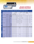
1
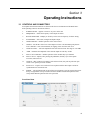
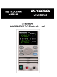
Model 4013DDS
12 MHz Sweep Function
Generator
1
Model 4013DDS - Instruction Manual
Limited Three-Year Warranty
B&K Precision warrants to the original purchaser that its products and the component parts thereof,
will be free from defects in workmanship and materials for a period of three years from date of
purchase from an authorized B&K Precision distributor.
B&K Precision will, without charge, repair or replace, at its option, defective product or component
parts. Returned product must be accompanied by proof of the purchase date in the form of a sales
receipt.
To obtain warranty coverage in the U.S.A., this product must be registered by completing the
warranty registration form on www.bkprecision.com within fifteen (15) days of purchase.
Exclusions: This warranty does not apply in the event of misuse or abuse of the product or
as a result of unauthorized alterations or repairs. The warranty is void if the serial number is
altered, defaced or removed.
B&K Precision shall not be liable for any consequential damages, including without limitation
damages resulting from loss of use. Some states do not allow limitations of incidental or
consequential damages. So the above limitation or exclusion may not apply to you.
This warranty gives you specific rights and you may have other rights, which vary from state-tostate.
Service Information
Warranty Service: Please return the product in the original packaging with proof of purchase to
the address below. Clearly state in writing the performance problem and return any leads, probes,
connectors and accessories that you are using with the device.
Non-Warranty Service: Return the product in the original packaging to the address below. Clearly
state in writing the performance problem and return any leads, probes, connectors and accessories
that you are using with the device. Customers not on open account must include payment in the
form of a money order or credit card. For the most current repair charges please visit
www.bkprecision.com and click on “service/repair”.
Return all merchandise to B&K Precision with pre-paid shipping. The flat-rate repair charge for
Non-Warranty Service does not include return shipping. Return shipping to locations in North
American is included for Warranty Service only. For overnight shipments and non-North American
shipping fees please contact B&K Precision.
B&K Precision
22820 Savi Ranch Parkway
Yorba Linda, CA 92887
www.bkprecision.com
714-921-9095
Include with the returned instrument your complete return shipping address, contact name,
phone number and description of problem.
2
Contents
Section 1
Section 2
Section 3
Introduction
1.2
DESCRIPTION ..........................................................................................................
5
1.3
SPECIFICATIONS ....................................................................................................
5
1.4
TECHNICAL SUPPORT...........................................................................................
6
Installation
2.1
INTRODUCTION......................................................................................................
7
2.3
INSTRUMENT MOUNTING ...................................................................................
7
2.4
POWER REQUIREMENTS ......................................................................................
7
2.5
GROUNDING REQUIREMENTS ............................................................................
7
2.6
SIGNAL CONNECTIONS ........................................................................................
8
2.7
ACCEPTANCE CHECK ...........................................................................................
8
Operating Instructions
3.1
CONTROLS AND CONNECTORS..........................................................................
9
3.2
INSTRUMENT INPUTS AND OUTPUTS...............................................................
10
3.4
FIRST TIME OPERATION.......................................................................................
10
3.5
DETAILED OPERATING INSTRUCTIONS ...........................................................
11
3
Model 4013DDS - Instruction Manual
Safety Summary
The following safety precautions apply to both operating and maintenance personnel and must be observed
during all phases of operation, service, and repair of this instrument. Before applying power, follow the
installation instructions and become familiar with the operating instructions for this instrument.
Failure to comply with these precautions or with specific warnings elsewhere in this manual violates safety
standards of design, manufacture, and intended use of the instrument. B&K assumes no liability for a
customer’s failure to comply with these requirements. This is a Safety Class I instrument.
GROUND THE INSTRUMENT
To minimize shock hazard, the instrument chassis and cabinet must be connected to an electrical ground. This
instrument is grounded through the ground conductor of the supplied, three-conductor ac power cable. The
power cable must be plugged into an approved three-conductor electrical outlet. Do not alter the ground
connection. Without the protective ground connection, all accessible conductive parts (including control
knobs) can render an electric shock. The power jack and mating plug of the power cable meet IEC safety
standards.
DO NOT OPERATE IN AN EXPLOSIVE ATMOSPHERE
Do not operate the instrument in the presence of flammable gases or fumes. Operation of any electrical
instrument in such an environment constitutes a definite safety hazard.
KEEP AWAY FROM LIVE CIRCUITS
Instrument covers must not be removed by operating personnel. Component replacement and internal
adjustments must be made by qualified maintenance personnel. Disconnect the power cord before removing
the instrument covers and replacing components. Under certain conditions, even with the power cable
removed, dangerous voltages may exist. To avoid injuries, always disconnect power and discharge circuits
before touching them.
DO NOT SERVICE OR ADJUST ALONE
Do not attempt any internal service or adjustment unless another person, capable of rendering first aid and
resuscitation, is present.
Do not install substitute parts or perform any unauthorized modifications to this instrument. Return the
instrument to vendor for service and repair to ensure that safety features are maintained.
WARNINGS AND CAUTIONS
WARNING and CAUTION statements, such as the following examples, denote a hazard and appear
throughout this manual. Follow all instructions contained in these statements.
A WARNING statement calls attention to an operating procedure, practice, or condition, which, if not
followed correctly, could result in injury or death to personnel.
A CAUTION statement calls attention to an operating procedure, practice, or condition, which, if not followed
correctly, could result in damage to or destruction of part or all of the product.
4
WARNING:
Do not alter the ground connection. Without the protective ground connection, all
accessible conductive parts (including control knobs) can render an electric
shock. The power jack and mating plug of the power cable meet IEC safety
standards.
WARNING:
To avoid electrical shock hazard, disconnect power cord before removing covers.
Refer servicing to qualified personnel.
CAUTION:
Before connecting the line cord to the AC mains, check the rear panel AC line
voltage indicator. Applying a line voltage other than the indicated voltage can
destroy the AC line fuses. For continued fire protection, replace fuses only with
those of the specified voltage and current ratings.
Section 1
Introduction
1.1 SCOPE
This manual contains installation instructions, test procedures, operation procedures and
troubleshooting information required to operate, test and maintain the Model 4013DDS Function
Generator.
1.2 DESCRIPTION
The Model 4013DDS is a versatile, high performance function generator. Implemented using
advance digital technologies based on DDS topology, the unit generate superb quality waveforms
with high precision and stability.
It provides sine & square wave outputs over the frequency range from 0.1 Hz to 12 MHz in one
extended range (triangle/ramped wave outputs to 1MHz).
An auxiliary TTL output at the generator frequency is available to synchronize external devices.
The output voltage can be varied from 0V to 10V peak-to-peak into 50 ohms or to 20V into open
circuit. A front panel pushbutton can attenuate the output by 20 dB. The DC level of the output can
be adjusted using the offset control.
1.3 SPECIFICATIONS
1.3.1 Waveforms
Sine, square and triangle waveforms
1.3.2 Operating Modes
CONTINUOUS ............................................................. Output continuous at selected frequency.
SYMMETRY ................................................................. Square symmetry is continuously adjustable from 15% to 85%.
SWEEP ……………………………………………………….. The output waveform can be linear or logarithmic internally swept,
up or down, over the full unit range. The sweep start and stop
frequencies can be independently adjusted and the sweep rate
can be set from 100ms to 30s.
1.3.3 Frequency Characteristics
RANGE ........................................................................ 0.2 Hz to 12 MHz for Sine and Square waveforms. To 1 MHz for
Triangle waveforms.
CONTROL ................................................................... The frequency is selected with front panel up or down keys and
modified with a rotary digital control.
DISPLAY ...................................................................... Up to 4 digits with large, bright LCD, ranging units (MHz, KHz, Hz
and mHz) and decimal point. Waveform accuracy is 0.01% ± 0.186
Hz.
1.3.4 Output Characteristics
AMPLITUDE RANGE ................................................... Up to 10V p-p into 50Ω (20V p-p into open circuit)
AMPLITUDE CONTROL .............................................. >20 dB continuously variable.
AMPLITUDE ATTENUATOR ....................................... 20 dB.
AMPLITUDE FLATNESS ............................................. ±1 dB to 12 MHz.
5
Model 4013DDS - Instruction Manual
OFFSET RANGE ......................................................... Variable up to ±10V (±5V into 50Ω). Absolute peak amplitude plus
offset limited to ±10V (±5V into 50Ω).
OUTPUT IMPEDANCE ................................................ 50Ω
OUTPUT PROTECTION .............................................. The generator main output is non-destructively protected against
short circuit to ground or to any voltage practically available in
electronic laboratories.
1.3.5 Waveform Characteristics
HARMONIC DISTORTION........................................... < -55dBc, 0 - 20 KHz, (<0.25%)
< -50 dBc, 20 KHz - 100 KHz
< -45 dBc, 100 KHz – 1 MHz
< -35 dBc, 1 MHz – 12 MHz
SPURIOUS ................................................................. < -55 dBc, 0 - 1 MHz
TRIANGLE LINEARITY ................................................ >99% to 100 KHz.
SQUARE TRANSITION TIMES ................................... <20 ns (10% to 90%) at full output amplitude terminated into 50Ω.
1.3.6 Inputs and Outputs
SYNC OUT................................................................... TTL level square wave at generator frequency, in phase with main
output and 50Ω impedance. Can drive > 20 TTL loads.
1.3.7 General
OPERATING TEMPERATURE .................................... 0°C to +50°C
POWER REQUIREMENTS .......................................... 100V–240V , ± 10%, 48–66 Hz single phase, <25 VA.
DIMENSIONS .............................................................. 8.4 inch (213 mm) wide; 8.3 inch (210 mm) deep;
3.5 inch (88 mm) high, without bumpers.
WEIGHT ....................................................................... Aprox 2 kg
REGULATORY STANDARDS ........ ............................ IEC 1010-1, Insulation category II, Pollution Degree 2.
EMC ............................................................................. EN50081-1 and EN50082-1.
CE Labeled
NOTES ......................................................................... Specifications apply at 25±5°C ambient temperature and after 30
minutes warm up.
Specifications are subject to change without notice.
For the most current product information please visit www.bkprecision.com.
1.4 TECHNICAL SUPPORT
If this product fails to operate upon arrival, contact your B&K PRECISION dealer or the factory to
arrange for service or exchange.
To arrange technical assistance or for service, contact the factory at:
B&K Precision Corp.
22820 Savi Ranch Parkway
Yorba Linda, CA 92887
714-921-9095
www.bkprecision.com
6
Section 2
Installation
2.1 INTRODUCTION
This section contains installation information, power requirements and an acceptance check for the
Model 4013DDS Function Generator.
2.2 MECHANICAL INSPECTION
This instrument was carefully inspected before shipment. Upon receipt, inspect the instrument for
damage that might have occurred in transit. If there is damage due to shipping, file a claim with the
carrier who transported the unit. The shipping container and packing material should be saved in
case reshipment is required. If the original container is not be used, then use a heavy carton box.
Wrap the unit with plastic and place cardboard strips across the face for protection. Use packing
material around all sides of the container and seal it with tape bands. Mark the box with
“FRAGILE”.
2.3 INSTRUMENT MOUNTING
The Model 4007DDS is intended for bench use. The unit can be installed in a closed rack or test
stand if proper airflow is assured for removing about 15W of power dissipation. The instrument
does not require special cooling when operated within conventional temperature limits. The
instrument includes a front feet tilt mechanism for optimum panel viewing angle.
2.4 POWER REQUIREMENTS
The Model 4013DDS can operate from 115/230 Vac, 50/60Hz. The maximum power consumption
is less than 25VA.
CAUTION:
Before connecting the line cord to the AC mains, check the rear panel AC line
voltage indicator. Applying a line voltage other than the indicated voltage can
destroy the AC line fuses. For continued fire protection, replace fuses only with
those of the specified voltage and current ratings.
Use only fuses of 0.5A SLO-BLO or IEC127 T type rated for 250V. The ac line fuse is located in
the Fuse Holder Assembly. To access the fuse, first disconnect the power cord and then remove the
fuse cartridge.
2.5 GROUNDING REQUIREMENTS
To minimize shock hazard, the instrument chassis and cabinet must be connected to an electrical
ground. This instrument is grounded through the ground conductor of the supplied, three-conductor
ac power cable. The power cable must be plugged into an approved three-conductor electrical
outlet.
WARNING:
Do not alter the ground connection. Without the protective ground connection, all
accessible conductive parts (including control knobs) can render an electric
shock. The power jack and mating plug of the power cable meet IEC safety
standards.
7
Model 4013DDS - Instruction Manual
2.6 SIGNAL CONNECTIONS
Use RG 58 coaxial cables for all input and output signals to and from the unit.
2.7 ACCEPTANCE CHECK
This acceptance check is a general verification of generator operation. Set the power on and allow a
15-minute warm-up period. Should a malfunction be found, refer to the Technical Service
information on page 6 of this manual.
2.7.1 Output Level
Connect an oscilloscope to the instrument output. Set the Model 4007 controls as follows:
WAVEFORM ...................... SINE
FREQUENCY ...................... 1 KHz
OFFSET ............................... OFF
ATTENUATOR ................... OUT
AMPLITUDE ....................... FULL CW
DUTY CYCLE..................... OFF
Observe a 20V peak-to-peak sine wave on the scope display. Connect a 50 ohms feed through
between the unit and an oscilloscope, and verify a 10V peak-to-peak waveform on display. Change
the amplitude control position to decrease the output voltage. Push the attenuator pushbutton and
measure an attenuation factor of 10 for the 20 dB step. Repeat paragraph 2.7.1 for triangle and
square wave output.
2.7.2 Offset Control
With the set up of 2.7.1, push the offset control. Rotate the offset knob from full CCW to full CW
and observe a waveform change from negative to positive level. The maximum DC plus peak is
limit to ±10V (un-terminated) or ±5V (50 ohms terminated).
2.7.3 Frequency
Connect a counter to the instrument output. Set the instrument controls as follows:
WAVEFORM ...................... SINE
OFFSET ............................... OFF
ATTENUATOR ................... OUT
AMPLITUDE ....................... MIDRANGE
DUTY CYCLE..................... OFF
Change the frequency and range and read the counter indications. The reading should fall between
instrument specifications.
2.7.4 Sync Output
Connect the scope to the SYNC output. Use the set up of paragraph 2.7.1. Observe a square wave,
of no less than 2V amplitude, and with 50% symmetry.
2.7.5 Symmetry
With the set up of paragraph 2.7.1, select Square waveform and push the DUTY CYCLE ON
control. Rotate the DUTY CYCLE knob from full CCW to CW and observe a waveform symmetry
change.
8
Section 3
Operating Instructions
3.1 CONTROLS AND CONNECTORS
Front panel controls and connectors are shown in the front view illustration of the Model 4013.
Each operating control is described as follows:
1.
POWER ON/OFF – Applies or removes AC power to the unit.
2.
FREQUENCY – Selects the frequency of the output waveform.
3.
RANGE SWITCHES – Multiply or divide by 10 the selected frequency for faster setting.
4.
WAVEFORM – Select Sine, Triangle and Square output.
5.
OFFSET ON/OFF – Enables operation of the offset control.
6.
OFFSET – Sets the DC offset level of the output waveform. The maximum peak plus DC
level is limited to ±10V (non terminated) or clipping of the waveform will occur.
7.
OUTPUT LEVEL – Varies the amplitude of the selected waveform. The range is over 20dB.
8.
-20dB – Attenuates the amplitude of the selected output waveform by 20-dB.
9.
DUTY CYCLE ON/OFF – Enables operation of the variable duty cycle function.
10.
DUTY CYCLE – Adjusts, after pressing the pushbutton, the duty cycle of the Square
waveform, when selected.
11.
OUTPUT – BNC connector for output of selected waveform; 20V peak-to-peak into open
circuit or 10V peak-to-peak into 50 ohms.
12.
SYNC OUT – A square wave with TTL levels in phase with the main output. Useful for
synchronization of external devices.
13.
SWEEP – The ON button turns on and off the sweep function as well as selecting the Linear
Sweep or Logarithmic Sweep. The SET selects the START and STOP frequencies of the
sweep and the RATE repetition of the sweep selected.
Front Panel View
9
Model 4013DDS - Instruction Manual
3.2 INSTRUMENT INPUTS AND OUTPUTS
The Model 4013 main output impedance is 50Ω. The output can deliver up to 10V peak-to-peak
waveforms into a 50Ω load. Proper signal loading and connection is necessary for the generator
main output to meet its specifications. An RG-58 coaxial cable equipped with BNC connectors and
terminated with a 50Ω feed through termination is recommended. Using the 50Ω terminator
minimizes signal reflection and power losses on the line due to the impedance mismatch. At higher
frequencies, an un-terminated or improperly terminated output will cause aberrations on the output
waveform.
Impedance Matching
If the waveform generator is driving a high impedance, such as the 1 MΩ input impedance of an
oscilloscope vertical input, connect the transmission line to a 50 ohms attenuator or a 50 ohms
termination and to the oscilloscope input. The attenuator isolates the input capacitance of the device
and terminates the waveform generator properly.
3.3 SYNC OUTPUT
A square wave output signal at the main output frequency is available at this output, producing TTL
levels with a 50Ω source impedance. This output is protected from short circuit and can drive a
minimum of 20 TTL loads. Leads connected to the SYNC OUT should be as short as possible to
prevent rounding of the TTL pulse. The SYNC output signal symmetry is changed by using the
DUTY CYCLE control for all selected waveforms.
3.4 FIRST TIME OPERATION
The following exercise will familiarize the operator with most functions of the Model 4013 function
generator. Preset the controls as follows:
WAVEFORM ...................... SINE
DUTY CYCLE..................... OFF
OFFSET .............................. OFF
ATTENUATOR ................... OFF
AMPLITUDE ....................... CENTERED
Connect a 50Ω coaxial cable, terminated into a 50Ω feedthrough, to the vertical input of an
oscilloscope (set vertical to 2V/Div and horizontal to 1 ms/Div). The oscilloscope should display a
triangle waveform.
10
1.
Alternately press the sine, square and triangle pushbuttons and observe the different wave
shapes. Return to the sine function.
2.
Rotate the frequency knob and press up and down range switches while observing the change
in frequency of the displayed waveform.
3.
Push the DUTY CYCLE ON button. Select the SQUARE wave. Rotate the control while
observing the change in the duty cycle of the waveform
4.
Alternately press the 20 dB attenuator button and rotate the AMPLITUDE control to verify
that the waveform amplitude changes. Return these controls to the preset condition.
5.
Push the OFFSET ON button and rotate the OFFSET control. Notice the change in DC level
of the displayed waveform. Return these controls to the preset condition.
3.5 DETAILED OPERATING INSTRUCTIONS
3.5.1 Frequency Setting
The frequency of the generator is changed by turning the FREQUENCY control. The frequency
range is selected by pressing the up or down range pushbuttons. The waveform output frequency is
shown on the LCD display.
3.5.2 Variable Symmetry
The symmetry of the Square waveform can be changed by pushing the DUTY CYCLE ON button
and rotating the DUTY CYCLE knob. A change of symmetry from 15% to 85% can be obtained.
3.5.3 Output Attenuation
The pushbutton attenuator of 20 dB attenuates the waveform by a factor of 10. In order to achieve
low noise waveforms at low levels, use proper attenuation and keep the amplitude control far from
its maximum CCW position.
3.5.4 Offset Output
DC voltage appears at the main output by pushing the OFFSET ON button. By rotating the
OFFSET control knob from CCW to CW, the output level and polarity are changed from negative
to positive. This level is also controlled by the output attenuator. DC offset is achieved by adding
the above DC output to any of the output waveforms selected by pressing the function buttons. A
maximum open circuit offset voltage of ±10V can be obtained. It should be noted that the peak
voltage of the signal, including DC and AC cannot exceed ±10V into open circuit and ±5V into
50Ω. The maximum current which can be taken from the output in DC or AC modes is limited to
100 mA maximum.
3.5.5 Sweep Operation
The internal sweep mode allows an overview of the frequency sensitive characteristics of a device
under test. In the mode the frequency of the selected waveform is swept from the selected start to
selected stop frequency. When the stop frequency is reached, the instrument resets to the start
frequency, and repeats.
1.
Press the Sweep ON button to set either Lin (linear) or Log (logarithmic) operation.
Pressing the ON button a third time will turn the sweep function off.
2.
Press the Sweep SET Button to set the sweep start frequency
3.
Use the RANGE Button & the Main Frequency Control Knob to set the desired sweep start
frequency
4.
Press the Sweep SET Button to set the sweep stop frequency
5.
Use the RANGE Button & the Main Frequency Control Knob to set the desired sweep stop
frequency
6.
Press the Sweep SET Button to set the sweep rate
7.
Use the RANGE Button & the Main Frequency Control Knob to set the desired sweep rate
11
Model 4013DDS - Instruction Manual
V092612
12