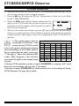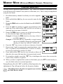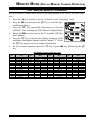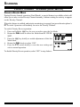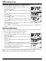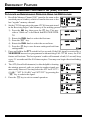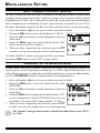
1
144/430 MHz
DUAL BAND FM TRANSCEIVER
WITH GPS
VX-8GR/GE
OPERATING MANUAL
VERTEX STANDARD CO., LTD.
4-8-8 Nakameguro, Meguro-Ku, Tokyo 153-8644, Japan
VERTEX STANDARD U.S.A. Inc.
6125 Phyllis Drive, Cypress, California 90630, U.S.A.
YAESU UK LTD.
Unit 12, Sun Valley Business Park, Winnall Close
Winchester, Hampshire, SO23 0LB, U.K.
VERTEX STANDARD HK LTD.
Unit 1306-1308, 13F., Millennium City 2, 378 Kwun Tong Road,
Kwun Tong, Kowloon, Hong Kong
VERTEX STANDARD (AUSTRALIA) PTY., LTD.
Tally Ho Business Park, 10 Wesley Court, East Burwood, VIC, 3151
Contents
Introduction ................................................................................. 1
Controls &Connections ............................................................... 2
Display Icons & Indicators ......................................................... 3
Keypad Functions ....................................................................... 4
Accessories & Option .................................................................. 6
Accessories Supplied with the VX-8GR .................................. 6
Available Options for your VX-8GR ....................................... 7
Installation of Accessories ........................................................... 8
Antenna Installation ................................................................. 8
Belt Clip Installation ................................................................ 8
Installation of FNB-101LI Battery Pack .................................. 9
Battery Life Information ........................................................ 10
Installation of FBA-39 Alkaline Battery Case ....................... 11
Interface of Packet TNCs .......................................................... 12
Operation ................................................................................... 13
Switching Power On and Off ................................................. 13
Adjusting the Volume Level .................................................. 13
Squelch Adjustment ............................................................... 14
Selecting the Operating Band ................................................ 15
Selecting the Frequency Band ................................................ 16
Frequency Navigation ............................................................ 17
Sub Band Operation ......................................................... 17
1) Tuning Dial .................................................................. 17
2) Direct Keypad Frequency Entry .................................. 17
3) Scanning ....................................................................... 18
Transmission .......................................................................... 19
Changing the Transmitter Power Level ............................ 19
Advanced Operation ................................................................. 21
Keyboard Locking ................................................................. 21
Adjusting the Keypad Beeper Volume Level ......................... 22
Setting the Frequency Display Image Size ............................. 22
Audio Muting ......................................................................... 23
Keypad/LCD Illumination ...................................................... 23
Changing the Channel Steps .................................................. 24
Changing the Receiving Mode ............................................... 24
SQL S-meter .......................................................................... 25
Repeater Operation ................................................................... 26
General ................................................................................... 26
Repeater Shifts ....................................................................... 26
Automatic Repeater Shift (ARS) ........................................... 26
Manual Repeater Shift Activation .......................................... 27
Changing the Default Repeater Shifts .............................. 27
Tone Calling (1750 Hz) ......................................................... 28
Checking the Repeater Uplink (Input) Frequency ................. 28
CTCSS/DCS/EPCS Operation ................................................. 29
CTCSS Operation .................................................................. 29
DCS Operation ...................................................................... 30
DCS Code Inversion ........................................................ 32
Tone Search Scanning ........................................................... 34
EPCS (Enhanced Paging & Code Squelch) ........................... 35
Storing the CTCSS Tone Pairs for EPCS Operation ....... 35
Activating the Enhanced Paging & Code Squelch System .. 36
Paging Answer Back ........................................................ 36
CTCSS/DCS/EPCS Bell Operation ....................................... 37
Programming the User Melody ........................................ 38
Split Tone Operation .............................................................. 39
CTCSS/DCS/EPCS Vibrator Operation ................................ 40
Memory Mode (Regular Memory Channel Operation) ......... 42
Memory Storage .................................................................... 43
Storing Independent Transmit Frequency (“Odd Splits”) ... 44
Memory Recall ....................................................................... 44
HOME Channel Memory ....................................................... 45
Labeling Memories ................................................................ 46
Memory Offset Tuning .......................................................... 47
Masking Memories ................................................................ 48
Memory Bank Operation ....................................................... 49
Assigning Memories to a Memory Bank .......................... 49
Memory Bank Recall ........................................................ 49
Removing Memories from a Memory Bank ..................... 50
Changing a Memory Bank’s Name .................................. 50
Moving Memory Data to the VFO ........................................ 51
Memory Only Mode ............................................................... 51
Memory Mode (Special Memory Channel Operation) .......... 52
Weather Broadcast Channels ................................................. 52
VHF Marine Memory Channels ............................................. 53
Scanning ..................................................................................... 54
General ................................................................................... 54
VFO Scanning ........................................................................ 56
How to Skip (Omit) a Frequency during VFO Scan ........ 57
Memory Scanning .................................................................. 58
How to Skip (Omit) a Channel during Memory Scan ...... 59
Preferential Memory Scan ................................................ 59
Memory Bank Scan .......................................................... 61
Programmable (Band Limit) Memory Scan (PMS) ............... 62
“Priority Channel” Scanning (Dual Watch) ........................... 63
Priority Revert Mode ....................................................... 64
Automatic Lamp Illumination on Scan Stop .......................... 65
Band Edge Beeper ................................................................. 65
GPS Operation .......................................................................... 66
Setting the Time Zone (Time Offset) ..................................... 67
Selecting the Display Units of the GPS Screen ...................... 68
Selecting the Map Datum ...................................................... 68
APRS® Operation ...................................................................... 70
Preparations ........................................................................... 70
Receiving an APRS Beacon ................................................... 73
Transmit an APRS Beacon .................................................... 76
Receiving an APRS Message ................................................. 79
Transmit an APRS Message .................................................. 81
ARTSTM (Automatic Range Transponder System) ................ 83
Basic ARTSTM Setup and Operation ..................................... 84
ARTSTM Polling Time Options .............................................. 84
ARTSTM Alert Beep Options ................................................. 85
CW Identifier Setup ............................................................... 86
Spectrum Analyzer Operation ................................................. 87
Smart Search Operation ........................................................... 88
Message Feature ........................................................................ 90
General ................................................................................... 90
Programming a Message ........................................................ 90
Programming a Member List ................................................. 91
Set your Personal ID .............................................................. 92
Sending a Message ................................................................. 93
Receiving a Message .............................................................. 94
Emergency Feature ................................................................... 95
Emergency Channel Operation .............................................. 95
Emergency Automatic ID (EAI) feature ................................ 96
Selecting the EAI mode and its Transmit Time ................ 97
Activating the EAI feature ............................................... 97
To Locate an Unresponsive Operator
using the EAI feature ............ 98
Internet Connection Feature .................................................... 99
General ................................................................................... 99
SRG (“Sister Radio Group”) Mode ....................................... 99
FRG (“Friendly Radio Group”) Mode ................................. 100
DTMF Operation ..................................................................... 102
CW Learning Feature ............................................................. 104
CW Training Feature .............................................................. 106
Sensor Mode ............................................................................. 107
Clock Set ............................................................................. 107
Miscellaneous Setting .............................................................. 108
Password .............................................................................. 108
Programming the d Key .................................................. 110
ATT (Front End Attenuator) ............................................... 111
Receive Battery Saver Setup ............................................... 112
TX Battery Saver ................................................................. 112
Disabling the BUSY Indicator ............................................. 113
Automatic Power-Off (APO Feature) .................................. 113
Transmitter Time-Out Timer (TOT) .................................... 114
ON/OFF Preset Timer .......................................................... 115
Busy Channel Lock-Out (BCLO) ........................................ 116
Changing the TX Deviation Level ....................................... 116
Changing the Microphone Gain ........................................... 117
S-and TX Power Meter Symbols ......................................... 117
Display Contrast .................................................................. 118
Display Dimmer ................................................................... 118
My Bands Operation ............................................................ 119
Changing the Status of the g Key .................................... 120
Reset Procedures ..................................................................... 121
Cloning ..................................................................................... 122
Set Mode ................................................................................... 124
APRS/GPS Set Mode .............................................................. 148
Specifications ........................................................................... 160
Appendix (Computer Connections) ....................................... 162
FCC Notice ............................................................................... 164
INTRODUCTION
The Ultra Compact VX-8GR/GE (2.4”W x 3.7”H x 1.1”D) is equipped with a GPS receiver and
thinner than the previous advanced model - It is packed with advanced technology and features, designed for outdoor operation. It is submersible (IPX5) and shockproof! The compact
case combines a rugged die-cast chassis with the clean, tough polycarbonate resin front panel.
Its shockproof versatility will allow you to operate the radio in the toughest environments.
The large High-resolution Dot Matrix LCD display provides clear, easy-to-read indication of
both “A” (Main band) and “B” (Sub band) frequencies, the operating mode, and S-meters for
both bands. When you engage the Spectrum Scope function, the high-resolution display will
indicate relative signal strengths of up to ±50 adjacent channels!
The built-in worldwide standard AX.25 Data TNC Modem permits uncomplicated APRS®
operation. (Automatic Packet/Position Reporting System: APRS® is a registered trademark of
the APRS Software and Bob Bruninga, WB4APR.) The VX-8GR/GE supports APRS® 1200/
9600 bps data communication on the “B” (Sub band) band only. You may communicate your
location to other APRS® stations along with the position, speed and heading displayed on your
radio! You and others will be able to see your APRS® movement on the web! The VX-8GR/
GE displays the received station’s positions, heading directions, messages, distances, icons (43
kinds), weather information, object, etc. With the list function you may automatically store and
recall up to 30 messages and the APRS® data from up to 50 stations. The built-in GPS Receiver
Unit provides you with real time APRS® data.
Enhanced Paging and Code Squelch (EPCS) allow you to page a particular station and only
receive calls from that station. A security Password may be set, which will allow you to turn on
and operate the transceiver only after you enter the Password. A convenient key provides access to Vertex Standard’s WIRES™ (Wide-Coverage Internet Repeater Enhancement System).
The Emergency Automatic ID (EAI) function can automatically cause your VX-8GR/GE to
transmit your callsign and engage your rig’s microphone, even if you are disabled and unable
to press the PTT switch. Additional features include: transmit Time-Out Timer (TOT), Automatic Power-Off (APO), and Automatic Repeater Shift (ARS). Yaesu’s exclusive ARTS™
(Auto-Range Transponder System) which “beeps” the user when you move out of communications range with another ARTS™ equipped station. There is provision to reduce the TX deviation for use in areas of high channel congestion. The squelch circuit allows adjusting the squelch
to open at a programmable setting of the S-Meter, thus reducing guesswork in setting the
squelch threshold. Provides a DATA jack which enables the display of location data (Lat/Lon)
from an after-market GPS receiver, and outputs the location data (Lat/Lon) of the built-in GPS
receiver unit and the Waypoint data of the received APRS beacons.
We appreciate your purchase of the VX-8GR/GE, and encourage you to read this manual
thoroughly, and learn about the many exciting features of your thrilling new Yaesu hand-held
transceiver!
VX-8GR/GE OPERATING MANUAL
1
CONTROLS & CONNECTIONS
ANTENNA Jack
Connect the supplied rubber flex antenna (or another
antenna presenting
a 50-Ohm impedance) here.
GPS RECEIVER
The internal GPS receiver is located
hear.
PTT Switch
(“Push To Talk”)
Press this switch inward to transmit, and
release it (to receive)
after your transmission is completed.
DIAL Knob
The main tuning Dial
is used to set the operating frequency,
and is also used for
audio volume level,
menu selections,
and other adjustments.
MIC/SP Jack
This four conductor
miniature jack allows
connection of an opt i o n a l M H - 3 4 B4B
Sp e a k e r M i c r o phone, MH-37 A4B
Ear piece/Microphone, or VC-25
VOX Headset.
MONI/T.CALL Key
USA version:
Pressing this key
disables the noise
squelching action,
allowing you to hear
very weak signals
near the background
noise level.
European version:
Pressing this key
activates the T.CALL
(1750 Hz) for repeater access.
DATA Jack
This three conductor
2.5-mm jack provides connection
points for an External computer.
VOL Key
Rotate the D I A L
knob while pressing
and holding this key
to adjust the audio
volume level.
EXT DC Jack
This coaxial DC jack
allows connection to
an external DC
power source (7.412V DC). The center
pin of this jack is the
Positive (+) line.
F/W Key
Pressing this key
activates the “Alternate” key functions
of the keypad.
p(PWR) Switch
Press and hold this
switch for 2 seconds
to toggle the
transceiver’s power
“on” and “off”.
Press this switch
briefly while the
transceiver is turned
“on” to toggle the key
lockout feature “on”
or “off”.
2
LED Light
This white LED will
glow (or flash) during
“Emergency Channel” operation. It can
also be useful as a
flash light in a dark
environment via the
Set Mode Item 45
LED LIGHT.
MIC
The internal microphone is located
here.
KEYPAD
The 18 front panel
key buttons select
many of the most important operating
features.
The functions of the
keys are described
in detail on pages 4
and 5.
TX/BUSY Lamps
These indicators
glow green when a
signal is being received and red when
transmitting.
SPEAKER
The internal speaker
is located here.
VX-8GR/GE OPERATING MANUAL
DISPLAY ICONS & INDICATORS
“A” Band
Display
“B” Band
Display
Icon
FREQUENCY CONTROL
VOLUME LEVEL
TX POWER LEVEL
VFO: VFO Mode
MR: Memory Mode
HI: High Power (5 W)
TUN: Memory Tune Mode
L3: LOW3 Power (2.5 W)
HOM: Home Channel Memory
L2: LOW2 Power (1 W)
PMS: Programmable Memory Scan Mode
L1: LOW1 Power (0.02 W)
VDW: Dual Watch Active
(VFO-Memory Channel)
OPERATING FREQUENCY
MDW:Dual Watch Active
(Memory Channel-Memory Channel)
S&PO METER
SMS: Smart Search Active
Note: When these icons blink, the Sub Band Operation features are active.
SQUELCH TYPE & RADIO MODE
TN:
TSQ:
DCS:
RTN:
PR:
PAG:
MSG:
DC:
T-D:
D-T:
A12:
A96:
Tone Encoder Active
Tone Squelch Active
Digital Code Squelch Active
Reverse Tone Squelch Active
User Programmed Reverse CTCSS Decoder Active
Enhanced Paging & Code Squelch (EPCS) Active
Message Feature Active
Split Tone Feature Active (DCS Encode only)
Split Tone Feature Active (Encodes a CTCSS Tone and Decodes a DCS Code)
Split Tone Feature Active (Encodes a DCS Code and Decodes a CTCSS Tone)
APRS® Feature Active (1200 bps)
APRS® Feature Active (9600 bps)
MISCELLANEOUS SETTING
:
:
:
:
:
Repeater Shift Direction (Minus Shift)
Repeater Shift Direction (Plus Shift)
Independent Transmit Frequencies
(Odd Splits)
Attenuator Active
Bell Alarm Active
OPERATING MODE
ICON
:
:
:
:
:
:
:
:
Secondary Keypad Active
Internet Connection Feature (WiRESTM) Active
DTMF Autodialer Active
Emergency Automatic ID (EAI) Feature Active
Automatic Power-Off Active
Key Lock Active
Mute Feature Active
Battery Saver Active
: Battery Indicator
NFM: FM
AM: AM
Note 1): When a bar is shown under these icons, the Vibrator function is active.
2): When a dashed bar is shown under these icons, the CTCSS/DCS/EPCS Vibrator function is active.
3): When a short-dashed bar is shown under these icons, the APRS Message Vibrator function is active.
VX-8GR/GE OPERATING MANUAL
3
KEYPAD FUNCTIONS
NOTE
Press the a or b
key to switch the frequency display between
the “Double-size Character” and “Small Character”
mode while in Mono band
operation.
PRIMARY FUNCTION
(PRESS KEY)
Switches the “Upper”
frequency to be the
“Operating” (TX) Band.
Switches the “Lower”
frequency to be the
“Operating” (TX) Band.
SECONDARY FUNCTION
(PRESS +
)
No Action
No Action
THIRD FUNCTION
(PRESS AND HOLD KEY)
Activates the
Dual Receive Feature.
Activates the
Dual Receive Feature.
PRIMARY FUNCTION
(PRESS KEY)
(1) Moves operation to the
next-highest frequency band.
(2) Activates the Memory Bank
feature.
Frequency entry digit “1”
Frequency entry digit “2”
SECONDARY FUNCTION
(PRESS +
)
Moves operation to the
next-lowest frequency band
Selects the synthesizer steps
to be used during VFO
operation.
Selects the CTCSS Tone,
DCS code, EPCS code, or
Message.
THIRD FUNCTION
(PRESS AND HOLD KEY)
(1) Select the Bandwidth for
the VFO scanner.
(2) Select the Memory Scan
mode.
No Action
No Action
PRIMARY FUNCTION
(PRESS KEY)
Reverses transmit and
receive frequencies while
working through a repeater.
Frequency entry digit “4”
Frequency entry digit “5”
SECONDARY FUNCTION
(PRESS +
)
Switches operation to the
“Home” (favorite frequency)
channel.
Activates the ARTS feature.
Activates the Memory Scan
“Skip” channel selection
mode.
THIRD FUNCTION
(PRESS AND HOLD KEY)
Activates the EMERGENCY
function.
No Action
No Action
PRIMARY FUNCTION
(PRESS KEY)
Activates the Internet
Connection feature.
Frequency entry digit “7”
Frequency entry digit “8”
SECONDARY FUNCTION
(PRESS +
)
Selects the desired transmit
power output level.
Activates the Audio Mute
Feature.
Activates the Spectrum
Analyzer (Spectra-ScopeTM)
feature.
THIRD FUNCTION
(PRESS AND HOLD KEY)
No Action.
No Action
No Action
4
VX-8GR/GE OPERATING MANUAL
KEYPAD FUNCTIONS
Activate the APRS
(Automatic Position
Reporting System) function.
PRIMARY FUNCTION
(PRESS KEY)
Activates the transmitter.
No Action
No Action
SECONDARY FUNCTION
(PRESS +
)
Activates the transmitter
temporarily in “high” power,
while the transceiver is in
“low” power operation.
Enter the Set Mode.
Toggle the transceiver’s
power “on” and “off”.
THIRD FUNCTION
(PRESS AND HOLD KEY)
Activates the Transmitter.
Frequency entry digit “3”
Selects the receive mode
between AM and FM.
PRIMARY FUNCTION
(PRESS KEY)
Selects the DTMF mode.
Activates the CTCSS
or DCS operation.
SECONDARY FUNCTION
(PRESS +
)
No Action
Engage the Special
Search mode.
THIRD FUNCTION
(PRESS AND HOLD KEY)
Frequency entry digit “6”
Switches frequency control
between the VFO and
Memory System.
PRIMARY FUNCTION
(PRESS KEY)
No Action
Selects the direction of the
uplink frequency shift (either
“–”, “+”, or “simplex”) during
repeater operation.
Activates the “Memory Tune”
mode while in the Memory
Recall mode.
SECONDARY FUNCTION
(PRESS +
)
Toggle the DIAL knob
function between the
“Frequency Control” and
“Receiver Audio Control”.
No Action
Activates the Priority (Dual
Watch) function.
THIRD FUNCTION
(PRESS AND HOLD KEY)
Rotate the DIAL knob while
holding this key to adjust the
audio volume level.
Frequency entry digit “9”
Frequency entry digit “0”
PRIMARY FUNCTION
(PRESS KEY)
Activates the “Secondary”
key function.
Enters the “Special Memory”
mode.
Activates the Sub Band
Operation feature.
SECONDARY FUNCTION
(PRESS +
)
Disables the “Secondary”
key function.
No Action
No Action
THIRD FUNCTION
(PRESS AND HOLD KEY)
Activates the “Memory Write”
mode (for memory channel
storage).
VX-8GR/GE OPERATING MANUAL
USA Version: Disables the Noise and
Tone Squelch System.
European Version: Activates the
T.CALL (1750 Hz) for repeater access.
USA Version: Adjusts the Squelch
threshold leve.
European Version: Activates the
T.CALL (1750 Hz) with “high” power.
USA Version: Disables the Noise and
Tone Squelch System.
European Version: Activates the
T.CALL (1750 Hz) for repeater access.
5
ACCESSORIES & OPTIONS
ACCESSORIES SUPPLIED WITH THE VX-8GR
Antenna
Li-Ion Battery Pack
Battery Charger
6
Belt Clip
Screws
Plastic Cap
Sheet
Operating Manual
Warranty Card
YHA-72 (Q3000236)
FNB-101LI (7.4V/1,100mAh: AAG10X001)
NC-86B (120 VAC, Type-A plug: Q9500149),
PA-44C (230 VAC, Type-C plug: Q9500165) or
PA-44U (230 VAC, Type-BF plug: Q9500166)
1 pc (RA1053600)
2 pcs (M3x10SUS: U24310020)
1 pc (RA1054200)
1 pcs (RA1231300)
1 pc
1 pc
1 pc
1 pc
1 pc
VX-8GR/GE OPERATING MANUAL
ACCESSORIES & OPTIONS
AVAILABLE OPTIONS FOR YOUR VX-8GR
CSC-95
FBA-39
FNB-101LI
FNB-102LI
CD-41
NC-86B
PA-44B/C/U
E-DC-5B
E-DC-6
CN-3
MH-34B4B
MH-37A4B
CT-44
CT-144
CT-143
Soft Case
3 x “AA” Cell Battery Case (batteries not supplied)
Li-Ion Battery Pack (7.4V/1,100 mAh)
Li-Ion Battery Pack (7.4V/1,800 mAh)
Rapid Charger (requires NC-86B/C/U or PA-44B/C/U)
Battery Charger for the CD-41 (for USA/EXP market)
Battery Charger for the CD-41 (for European market)
DC Cable w/Noise Filter (USA/EXP market only)
DC Cable; plug and wire only (USA/EXP market only)
BNC-to-SMA Adapter
Speaker/Microphone
Ear peace Microphone
Microphone Adapter
Clone Cable
PC Connection Cable
: “B” suffix is for use with 120 VAC (Type-A plug), “C” suffix is for use with 230 VAC
(Type-C plug), and “U” suffix is for use with 230 VAC (Type-BF plug).
Availability of accessories may vary. Some accessories are supplied as standard per local
requirements, while others may be unavailable in some regions. Consult your Yaesu Dealer
for details regarding these and any newly-available options. Connection of any non-Yaesu
approved accessory, should it cause damage, may void the Limited Warranty on this apparatus.
: USA/EXP market only
VX-8GR/GE OPERATING MANUAL
7
INSTALLATION OF ACCESSORIES
ANTENNA INSTALLATION
The supplied antenna provides good results over the entire frequency range of the transceiver. However, for enhanced base station medium-wave and shortwave reception, you
may wish to connect an external (outside) antenna.
TO INSTALL THE SUPPLIED ANTENNA
Hold the bottom end of the antenna, then screw it onto the mating connector on the transceiver until it is snug. Do not over-tighten by use of extreme force.
Notes:
Never transmit without having an antenna connected.
Carefully turn the supplied antenna onto the SMA jack. Never twist
the upper part of the antenna while screwing it onto the mating connector of the transceiver.
If using an external antenna for transmission, ensure that the SWR
presented to the transceiver is 1.5:1 or lower.
BELT CLIP INSTALLATION
Install the supplied Belt Clip to the FNB-101LI
Battery Pack using the supplied two screws
(Figure 1). Use only the screws included with
the Belt Clip to mount the Belt Clip to the back
of the Battery Pack!
If you do not need the Belt Clip, install the supplied Plastic Cap to the Battery Pack (Figure
2). If you install the belt clip later, push the Plastic Cap out with a small tool or screwdriver.
Figure 1
Figure 2
8
VX-8GR/GE OPERATING MANUAL
INSTALLATION OF ACCESSORIES
INSTALLATION OF FNB-101LI BATTERY PACK
The FNB-101LI is a high-performance Lithium-Ion battery providing high capacity in a
very compact package. Under normal use, the FNB-101LI may be used for approximately 300 charge cycles, after which operating time may be expected to decrease. An old
battery pack, which is displaying diminished capacity should be replaced with a new one.
To install the FNB-101LI Battery Pack, carefully mate the
battery’s three alignment tabs with their corresponding alignment slots on the transceiver bottom case, then gently press
the top side of the Battery Pack until it locks in place with a
“click”.
To remove the Battery Pack, turn the transceiver off and
remove any protective cases. Press the Battery Pack Release Knobs downward to unlock the latch, then remove
the Battery Pack from the transceiver.
1) The VX-8GR/GE battery must be correctly installed,
to maintain the waterproof integrity.
2) Always use the Vertex Standard Co., Ltd. Model FNB-101LI
or FNB-102LI Lithium-Ion Battery Pack.
3) Battery Pack shall not be exposed to excessive heat such as
sunshine, fire, or the like.
4) Risk of explosion if battery is replaced by an incorrect type.
Dispose of used batteries according to the instructions
INSTALL
BATTERY PACK RELEASE KNOB
REMOVE
If the battery has never been used, or its charge is depleted, it may be charged by connecting the NC-86/PA-44 Battery Charger, as shown in the illustration, to the EXT DC jack.
In the USA market, if only 12 ~ 16 Volt DC power is available, the optional E-DC-5B DC
Adapter (with its cigarette lighter plug) or E-DC-6 DC Cable may also be used for charging the battery, as shown in the illustration.
NC-86/PA-44
E-DC-5B
(USA MARKET ONLY)
VX-8GR/GE OPERATING MANUAL
E-DC-6
(USA MARKET ONLY)
9
INSTALLATION OF ACCESSORIES
INSTALLATION OF FNB-101LI BATTERY PACK
While the battery is being charged, the display will indicate “CHARGING” and the “A”
indicator will glow red. The S-meter will deflect according to the charging status. When
charging is finished, the display will change to indicate “COMPLETE” and the “A” indicator will glow green.
1) Turn the radio off while charging the battery.
2) Perform the battery charging where the ambient temperature range +41
°F to +95 °F (+5 °C to +35 °C). Charge out of this range could cause damage
to the battery pack.
3) Use only the Vertex Standard Co., Ltd. Model NC-86B (for USA market) or PA-44C/
U (for European market)Battery Charger.
BATTERY LIFE INFORMATION
When the battery charge is almost depleted, a “Low Voltage” indicator will appear on the
display. When this icon appears, it is recommended that you charge the battery soon.
BATTERY LIFE (A PPROX.)
FNB-101LI FNB-102LI
FBA-39
144 MHz
5.0 hours
8.5 hours
17 hours
430 MHz
5.0 hours
8.0 hours
16 hours
BATTERY INDICATOR
: Full battery power
: Enough battery power
: Low battery power
: Poor battery power
(w/Blink): Charge (or replace) the battery
OPERATING BAND
TX 6 seconds, RX 6 seconds, and Squelched 48 seconds (continuous operating cycle).
GPS receiver is “off”.
The present battery voltage can be displayed manually on the LCD, by following the
instructions on page 107.
Battery capacity may be reduced during extremely cold weather. Keeping the radio inside
your parka may help preserve the full charge capacity.
10
VX-8GR/GE OPERATING MANUAL
INSTALLATION OF ACCESSORIES
INSTALLATION OF FBA-39 ALKALINE BATTERY CASE (OPTION)
The optional FBA-39 Battery Case allows receive monitoring using three “AA” size Alkaline batteries. Alkaline batteries can also be used for low power transmission in an
emergency. The power output level selections will be limited to: 1 W/50 mW (for 144/430
MHz FM).
TO INSTALL ALKALINE BATTERIES INTO THE FBA-39
1. Lift up the lower right corner of the rubber cover, and then open the cover (Figure 1).
2. Referring to Figure 2, slide the batteries into the FBA-39 as shown in the illustration,
with the Negative [–] side of the batteries touching the spring connections inside the
FBA-39.
3. Close the rubber cover.
4. Install the FBA-39 in the transceiver in the same manner as the FNB-101LI.
Figure 1
Figure 2
The FBA-39 does not provide connections for charging, since Alkaline cells cannot be
re-charged. Therefore, the NC-86B, PA-44C/U, E-DC-5B, or E-DC-6 may safely be
connected to the EXT DC jack when the FBA-39 is installed (E-DC-5B and E-DC-6 are
usable only in a USA market).
Notes:
The FBA-39 is designed for use only with AA-type Alkaline cells.
If you do not use the VX-8GR/GE for a long time, remove the Alkaline batteries from
the FBA-39, as battery leakage could cause damage to the FBA-39 and/or the transceiver.
VX-8GR/GE OPERATING MANUAL
11
INTERFACE OF PACKET TNCS
The VX-8GR/GE may be used for Packet operation, using the optional CT-44 Microphone Adapter (available from your Yaesu dealer) for easy interconnection to commonlyavailable connectors wired to your TNC.
The audio level from the receiver to the TNC may be adjusted by rotating the DIAL knob
while pressing and holding the g key, as with voice operation. The input level to the
VX-8GR/GE from the TNC should be adjusted at the TNC side; the optimum input voltage is approximately 5 mV at 2000 Ohms.
Be sure to turn the transceiver and TNC off before connecting the cables, to prevent voltage spikes from damaging your transceiver.
MIC/SP Jack
CT-44 Microphone Adapter
TNC
EAR
10 µF
MIC
12
2 kΩ
SP
GND
MIC
PTT
GND
VX-8GR/GE OPERATING MANUAL
OPERATION
Hi! I’m R. F. Radio, and I’ll be helping you along as you learn the many
features of the VX-8GR/GE. I know you’re anxious to get on the air, but I
encourage you to read the “Operation” section of this manual as thoroughly
as possible, so you’ll get the most out of this fantastic new transceiver. Now. . .let’s get
operating!
SWITCHING POWER ON AND OFF
1. Be sure the battery pack is installed, and that it is fully charged. Connect the antenna
to the top panel ANTENNA jack.
2. Press and hold in the p(PWR) switch (on the left side
of the front panel) for 2 seconds. Two beeps will be heard
when the switch has been held long enough. The opening message will appear briefly on the display, then the
frequency display will appear. After another two seconds, the receive-mode Battery Saver function will become active, unless you have disabled it (see page 112).
3. To turn the VX-8GR/GE off, press and hold in the p (PWR) switch again for 2
seconds.
If you don’t hear the two “Beep” tones when the radio comes on, the Beeper
may have been disabled via the Menu system. See page 22, which tells you
how to reactivate the Beeper.
ADJUSTING THE VOLUME LEVEL
Rotate the DIAL knob while pressing and holding the g
key to set the desired audio level. Clockwise rotation increases the volume level.
1) The Volume level may be set on the
“A-Band” and “B-Band” separately.
2) While adjusting the Audio volume level, the
“SP VOLUME” notation appears in the S- & PO meter
area.
3) Pressing the f key followed by the g key, the DIAL knob function changes to the
Volume Level adjustment instead of the frequency control. In this case, the “Volume
Level Indicator” on the display blinks. Pressing the f key followed by the g key
again, returns the DIAL knob function to the frequency control. You may also change
the g key function via Set Mode Item 99: VOLUME MODE. See page 120 for details.
VX-8GR/GE OPERATING MANUAL
13
OPERATION
SQUELCH ADJUSTMENT
The VX-8GR/GE’s Squelch system allows you to mute the background noise when no
signal is being received. Not only does the Squelch system make “standby” operation
more pleasant, it also significantly reduces battery current consumption.
1. On the VX-8GR, press the f key, then press the e
key on the left side of the radio. This provides a “Shortcut” to Set Mode Item 85: SQL LEVEL.
On the VX-8GE, press and hold the m key for one
second to enter the Set Mode, rotate the DIAL knob to
select Set Mode Item 85: SQL LEVEL., then press the
m key briefly to enable selection of this Menu Item.
2. Now, rotate the DIAL knob to the point where the background noise is just silenced (typically at a setting of about
“3” or “4” on the scale); this is the point of maximum sensitivity to weak signals.
3. When you are satisfied with the Squelch threshold setting, press the PTT key briefly
to save the new setting and exit to normal operation.
4. You may also adjust the Squelch setting by using the “Set” (Menu) mode. See page
143 for details.
1) The Squelch level may be set on the “Main” and “Sub” bands separately.
2) If you’re operating in an area of high RF pollution, you may need to
consider “Tone Squelch” operation using the built-in CTCSS Decoder. This
feature will keep your radio quiet until a call is received from a station sending a carrier
which contains a matching (sub audible) CTCSS tone. Or if your friends have radios
equipped with DCS (Digital Coded Squelch) like your VX-8GR/GE, try using that mode
for silent monitoring of busy channels.
24-HOUR CLOCK
The VX-8GR/GE has a 24-hour clock with a calendar which covers all dates from
January 1, 2000 through December 31, 2099. Set the clock according to the “Clock
Set” column on page 107.
14
VX-8GR/GE OPERATING MANUAL
OPERATION
SELECTING THE OPERATING BAND
In the factory default configuration, the VX-8GR/GE operates in the “Dual Receive”
mode.
During Dual Receive operation, the “A-Band” frequency will be displayed on the upper
part of the LCD, and the “B-Band” frequency will be displayed on the lower part. The
“Operating” band (the band on which transmission and band/frequency changes are possible) is shown in large characters, and “Receive only” band is shown in small characters.
Press the a key briefly to engage the “A-Band” frequency as the “Operating” band. Alternatively, press the
b key briefly to engage the “B-Band” frequency, as described previously.
Press and hold in the a or b key for 1/2 seconds to
switch to Mono Band Operation. During Mono band operation, you may change the display between “double-size
character” and “large character” by pressing the a/b key.
VX-8GR/GE OPERATING MANUAL
15
OPERATION
SELECTING THE FREQUENCY BAND
The VX-8GR/GE covers an incredibly wide frequency range, over which a number of
different operating modes are used. Therefore, the VX-8GR/GE’s frequency coverage
has been divided into different operating bands. Each band has its own preset channel
steps and operating modes. You can change the channel steps and operating modes later, if
you like (see page 24).
TO CHANGE OPERATING BANDS
1. Press the B key repeatedly. You will see the LCD indication change to a higher
frequency band each time you press the B key. A Band Number according to the
receiving frequency is also displayed.
2. If you wish to move the operating band selection downward (toward lower frequencies), press the f key first, then press the B key.
3. The VX-8GR/GE uses a dual VFO system (described
previously). To switch TX/RX operation from the
“VFO-A” to the “VFO-B” instantly, press the b key
briefly. Pressing the a key will return TX/RX operation to “VFO-A”. The frequency band shown in
“Large” characters is the band on which transmission
is possible; the band shown in “Small” characters may
only be used for reception.
4. Once you have selected the desired band, you may initiate manual tuning (or scanning). See the discussions on the next page.
If desired, you may omit (skip) one or more bands from the band selection
loop for faster recall of your favorite operating bands. See page 119 for details.
OPERATING BAND
[BAND NUMBER]
AIR Band [1]
VHF HAM Band [2]
VHF Band [3]
INFO 1 Band [4]
UHF HAM Band [5]
UHF Band [6]
FREQUENCY RANGE
“VFO-A”
“VFO-B”
108-137 MHz
108-137 MHz
137-174 MHz
137-174 MHz
174-222 MHz
174-222 MHz
222-420 MHz
222-420 MHz
420-470 MHz
420-470 MHz
USA: 470-774 MHz
470-580 MHz
EU/EXP: 470-803 MHz
INFO 2 Band [7]
803-999.99 MHz
–
USA Version: Cellular Blocked
16
VX-8GR/GE OPERATING MANUAL
OPERATION
FREQUENCY NAVIGATION
The VX-8GR/GE will initially be operating in the “VFO” mode, as just described. This is a
frequency step system which allows free tuning throughout the currently-selected operating
band.
Three basic frequency navigation methods are available on the VX-8GR/GE:
1) TUNING DIAL
Rotation of the DIAL knob allows tuning in the pre-programmed steps established for the current operating band.
Clockwise rotation of the DIAL knob causes the VX-8GR/
GE to be tuned toward a higher frequency, while counterclockwise rotation will lower the operating frequency.
If you press the f key briefly, then rotate the DIAL knob,
frequency steps of 1 MHz will be selected. This feature is
extremely useful for making rapid frequency excursions over the wide tuning range of the
VX-8GR/GE.
2) DIRECT KEYPAD FREQUENCY ENTRY
The desired operating frequency may be entered directly from the keypad.
The operating mode will automatically be set once the new frequency is entered via the
keypad.
To enter a frequency from the keypad, just press the numbered digits on the keypad in the
proper sequence. There is no “Decimal point” key on the VX-8GR/GE. However, there is a
short-cut for frequencies ending in zero - press the c key after the last non-zero digit.
Examples:
To enter 145.520 MHz, press 145520
To enter 430.000MHz, press 43c
Sub Band Operation
key is pressed, followed by the
key, the controls (except the TX
When the
function) will act on the “Sub” band. When “Sub” Band
operation is activated, the “Sub” band “Frequency Control” icon will blink. After completing control of the
“Sub” band, press the
key followed by the
key
to return control to the “Main” band.
VX-8GR/GE OPERATING MANUAL
17
OPERATION
FREQUENCY NAVIGATION
3) SCANNING
From the VFO mode, press and hold in the B key for one second, and while still
holding in the B key, rotate the DIAL knob to select
the bandwidth for the VFO scanner. Release the B key
to begin scanning toward a higher frequency. The scanner
will stop when it receives a signal strong enough to break
through the Squelch threshold. The VX-8GR/GE will then
hold on that frequency according to the setting of the “RESUME” mode (Menu Item 77: SCAN RESUME).
If you wish to reverse the direction of the scan (i.e. toward a lower frequency, instead of a
higher frequency), just rotate the DIAL knob one click in the counter-clockwise direction
while the VX-8GR/GE is scanning. The scanning direction will be reversed. To revert to
scanning toward a higher frequency once more, rotate the DIAL knob one click clockwise.
Press the PTT switch briefly to cancel the scanning. See page 54 for more details regarding Scan Operation.
Dual Receive Notice
The VX-8GR/GE may receive very strong signals on the Image frequency, and/or
the receiver sensitivity may be somewhat reduced by the combination of the “ABand” and “B-Band” frequencies while Dual Receive operation is engaged.
If you experience interference that you suspect may be coming in via an “Image”
path, you may calculate the possible frequencies using the formulas below. This
information may be used in the design of effective countermeasures such as traps,
etc.
16.369 MHz x n
6.144 MHz x n
11.7 MHz x n
4.9152 MHz x n
9.8304 MHz x n
(n is an integer: 1, 2, 3, …)
“A-Band” Freq. = (“B-Band” Freq. ± 46.35 MHz) x n
“B-Band” Freq. = (“A-Band” Freq. ± 47.25 MHz) x n (@ “A-Band” = NFM)
18
VX-8GR/GE OPERATING MANUAL
OPERATION
TRANSMISSION
Once you have set up an appropriate frequency inside one of the dual amateur bands on
which the VX-8GR/GE can transmit (144 MHz or 430 MHz), you’re ready to transmit.
These are the most basic steps; more advanced aspects of transmitter operation will be
discussed later.
1. To transmit, press the PTT switch, and speak into the
front panel microphone (located in the upper right-hand
corner of the speaker grille) in a normal voice level.
The LED of the “A” or “B” which is designated the
“Main” band will glow red during transmission.
2. To return to the receive mode, release the PTT switch.
3. During transmission, the relative power level will be
indicated on the LCD. Additionally, the “L1”, “L2”, “L3”,
or “HI” icon will appear at the left side of the PO meter,
corresponding with the “Power” Level setting.
1) If you’re just talking to friends in the immediate
area, you’ll get much longer battery life by switching to Low Power operation. To do this, press the f key, then press the d key so that the “Low
Power” icon appears at the bottom of the display. And don’t forget: always have an
antenna connected when you transmit.
2) Transmission is not possible on the “Sub” band, nor on any frequencies other than
the 144 MHz and 430 MHz bands on the “Main” band.
3) Never transmit without having an antenna connected.
CHANGING THE TRANSMITTER POWER LEVEL
You can select between a total of four transmitter power levels on your VX-8GR/GE. The
exact power output will vary somewhat, depending on the voltage supplied to the transceiver. With the standard FNB-101LI Battery Pack and external DC source, the power
output levels available are: “L1”, “L2”, “L3”, or “HI”
To change the power level:
1. The default setting for the power output is “High;” in
this configuration, the display shows the “HI” icon.
Pressing the f key, followed by the d key, causes
the power level “L1”, “L2”, or “L3” to appear.
2. Press the f key, followed by the d key (repeatedly, if necessary) to make the “HI” icon appear and
restore “High Power” operation.
VX-8GR/GE OPERATING MANUAL
19
OPERATION
TRANSMISSION
)
1 The VX-8GR/GE is smart! You can set up Low power on one band (like
UHF), while leaving VHF on High power, and the radio will remember the
different settings on each band.
TRANSMIT POWER
FNB-101LI/-102LI
FBA-39
And when you store memories, you can store
(w/Fresh Batteries)
or EXT DC (7.4 V)
High and Low power settings separately in
HI: 5.0 W,
each memory, so you don’t waste battery
L3: 2.5 W,
L2: 1.0 W,
power when using very close-in repeaters!
L2: 1.0 W,
L1: 0.05 W
L1: 0.05 W
2) When you are operating on one of the Low
power settings, you can press the
key, then press the PTT switch, to cause the VX8GR/GE to transmit (temporarily) on High power. After one transmission, the power
level will revert to the previously-selected Low power setting.
20
VX-8GR/GE OPERATING MANUAL
ADVANCED OPERATION
Now that you mastered the basics of VX-8GR/GE operation, let’s learn more about some
of the really neat features.
KEYBOARD LOCKING
In order to prevent accidental frequency change or inadvertent transmission, various keys
and switches may be locked out. The possible lockout combinations are:
KEY:
DIAL:
KEY&DIAL:
PTT:
KEY&PTT:
DIAL&PTT:
ALL:
Just the front panel keys are locked out
Just the top panel DIAL knob is locked out
Both the DIAL knob and Keys are locked out
The PTT switch is locked (TX not possible)
Both the keys and PTT switch are locked out
Both the DIAL knob and PTT switch are locked out
All of the above are locked out
To lock out some or all of the keys:
1. Press and hold the m key for one second to enter the Set Mode.
2. Rotate the DIAL knob to select Set Mode Item 46: LOCK.
3. Press the m key briefly to enable selection of this Menu
Item.
4. Rotate the DIAL knob to choose between one of the locking schemes as outlined above.
5. When you have made your selection, press the PTT switch
to save the new setting and resume normal operation.
To activate the locking feature:
Press the p(PWR) switch briefly. The “k” icon will appear
on the LCD. To cancel locking, press the p(PWR) switch again.
Even when “ALL” keys have been locked out, one
key actually is not locked out: the p(PWR) switch
remains available so you can unlock your keypad when you want to!
VX-8GR/GE OPERATING MANUAL
21
ADVANCED OPERATION
ADJUSTING THE KEYPAD BEEPER VOLUME LEVEL
A keypad beeper provides useful audible feed back whenever a key button is pressed. The
keypad beeper level changes according to the receiver audio volume level setting. However, you may adjust the volume balance between the receiving audio and keypad beeper
using Set Mode Item 9: BEEP LEVEL.
1. Press and hold the m key for one second to enter the Set Mode.
2. Rotate the DIAL knob to select Set Mode Item 9: BEEP
LEVEL.
3. Press the m key briefly to enable selection of this Set
Mode Item.
4. Rotate the DIAL knob to select the desired level.
5. When you have made your choice, press the PTT switch to
save the new setting and return to normal operation.
Additionally, if you want to turn the beep off:
1. Press and hold the m key for one second to enter the Set Mode.
2. Rotate the DIAL knob to select Set Mode Item 11: BEEP
SELECT.
3. Press the m key briefly to enable selection of this Set
Mode Item.
4. Rotate the DIAL knob to change the setting to “OFF”.
5. When you have made your choice, press the PTT switch to
save the new setting and return to normal operation.
6. If you wish to re-enable the Beeper, just repeat the above
procedure, rotating the DIAL knob to select “KEY” or “KEY & SCAN” in step “4”
above.
KEY: The beeper sounds when you press any key.
KEY & SCAN: The beeper sounds when you press a key or when the scanner stops.
SETTING THE FREQUENCY DISPLAY IMAGE SIZE
When operating in “Mono” band, pressing the a or b key, causes the LCD to “toggle”
between display of double-size characters and large characters. However, this feature
does not work during Dual Receive operation, as both the “Main” band and “Sub” band
frequencies are shown on the display.
DOUBLE-SIZE CHARACTERS
22
LARGE CHARACTERS
VX-8GR/GE OPERATING MANUAL
ADVANCED OPERATION
AUDIO MUTING
The Audio Mute feature is useful in situations where it would be helpful to reduce the
audio level of the “Receive Only” band (Small character display) whenever you receive a
signal on the “Main” band (Large character display) during Dual Receive operation.
To activate the Audio Mute feature:
1. Press the f key, then press the 7 key. This provides a “Shortcut” to Set Mode Item 57: MUTE.
2. Rotate the DIAL knob to select the desired muting level
(MUTE 30%, MUTE 50%, MUTE 100%, or OFF).
3. When you have made your choice, press the PTT switch to save the new setting and
return to normal operation.
When the Audio Mute feature is activated, the “ ” icon will
appear on the display, and the “ ” icon blinks while muting the
“Receive Only” band audio.
To cancel the Audio Mute feature, just repeat the above procedures, selecting “OFF” in step 2 above.
KEYPAD/LCD ILLUMINATION
Your VX-8GR/GE includes a reddish illumination lamp which aids in nighttime operation. The red illumination yields clear viewing of the display in a dark environment, with
minimal degradation of your night vision. Three options for activating the lamp are provided:
KEY 2sec - KEY 10sec: Illuminates the Keypad/LCD for the selected illumination
time when any key is pressed.
CONTINUOUS:
Illuminates the Keypad/LCD continuously.
OFF:
Disables the Keypad/LCD lamp.
Here is the procedure for setting up the Lamp mode:
1. Press and hold the m key for one second to enter the Set Mode.
2. Rotate the DIAL knob to select Set Mode Item 41: LAMP.
3. Press the m key briefly to enable selection of this Set Mode
Item.
4. Rotate the DIAL knob to select one of the three modes described above.
5. When you have made your choice, press the PTT switch to
save the new setting and return to normal operation.
VX-8GR/GE OPERATING MANUAL
23
ADVANCED OPERATION
CHANGING THE CHANNEL STEPS
The VX-8GR/GE’s frequency synthesizer provides the option of utilizing tuning steps of
5, 6.25, 8.33, 10, 12.5, 15, 20, 25, 50 and 100 kHz per step. The VX-8GR/GE is set up at the
factory with different default steps for each operating band which are probably satisfactory
for most operation. However, if you need to change the channel step increments, the procedure to do so is very easy.
1. Press the f key, then press the 1 key on the left side of the radio. This provides a
“Short-cut” to Set Mode Item 89: STEP FREQUENCY.
2. Rotate the DIAL knob to select the desired step size.
3. Press the PTT switch to save the new setting and return to
normal operation.
1) 8.33 kHz steps are available only when receiving on the Air band.
2) 5 kHz steps are not available for use on 250 - 300 MHz, nor above 580
MHz.
CHANGING THE RECEIVING MODE
The VX-8GR/GE provides for automatic mode changing when the radio is tuned to different operating frequencies. However, should an unusual
receiving situation arise in which you need to change to a
different receiving mode, just press the
key. The receiving modes available are:
AUTO: The receive mode is automatically set according to the default values for the selected frequency range
NFM: Frequency Modulation
AM:
Amplitude Modulation
Unless you have a compelling reason to do so, leave the Automatic Mode
Selection feature on in order to save time and trouble when changing bands.
If you make a mode change for a particular frequency or station, you can
always store that one channel into memory, as the mode setting will be memorized along
with the frequency information.
24
VX-8GR/GE OPERATING MANUAL
ADVANCED OPERATION
SQL S-METER
A special SQL (Squelch) S-meter feature is provided on this radio. This feature allows
you to set the squelch so only signals exceeding a certain S-meter level will open the
squelch.
To set up the S-meter squelch feature for operation, use the following procedure:
1. Press and hold the m key for one second to enter the Set Mode.
2. Rotate the DIAL knob to select Set Mode Item 86: SQL SMETER.
3. Press the m key briefly to enable selection of this Set
Mode Item.
4. Rotate the DIAL knob to select the desired signal strength
level for the squelch threshold (LEVEL1 - LEVEL9 or OFF).
5. When you have made your choice, press the PTT switch to
save the new setting and return to normal operation.
1) When the SQL S-meter is activated, the S-meter segment corresponding to
the squelch threshold which was set by step 4 above will blink.
2) The receiver’s squelch will open based on the higher of the levels set by the
Noise Squelch or the S-meter Squelch system.
For example:
a) If the Noise Squelch (SQL control) is set so that signals at a level of “S-3” will open
the squelch, but the SQL S-meter (Set Mode Item 93) is set to “LEVEL 5,” the squelch
will only open on signals which are “S5” or stronger on the S-meter.
b) If the SQL S-meter is set to “S3,” but the Noise Squelch is set to a high level which
will only pass signals which are Full Scale on the S-meter, the squelch will only open on
signals which are Full Scale on the S-meter. In this case, the Noise Squelch overrides
the action of the S-meter Squelch.
VX-8GR/GE OPERATING MANUAL
25
REPEATER OPERATION
GENERAL
Repeater stations, usually located on mountaintops or other high locations, provide a dramatic extension of the communication range for low-powered hand-held or mobile transceivers. The VX-8GR/GE includes a number of features, which make repeater operation
simple and enjoyable.
REPEATER SHIFTS
Your VX-8GR/GE has been configured, at the factory, for the repeater shifts customary in
your country. For the 144 MHz band, this usually will be 600 kHz, while the 430 MHz
shift will be 1.6 MHz, 7.6 MHz, or 5 MHz (USA version).
Depending on the part of the band in which you are operating, the repeater shift may be
either downward ( ) or upward ( ),
and one of these icons will appear to
the right of the display frequency on
the LCD when repeater shifts have
been enabled.
AUTOMATIC REPEATER SHIFT (ARS)
The VX-8GR/GE provides a convenient Automatic Repeater Shift feature, which causes
the appropriate repeater shift to be automatically applied whenever you tune into the designated repeater sub-bands in your country. These sub-bands are shown below.
If the ARS feature does not appear to be working, you may have accidentally disabled it.
To re-enable ARS:
1. Press and hold the m key for one second to enter the Set Mode.
2. Rotate the DIAL knob to select Set Mode Item 69: RPT ARS.
3. Press the m key briefly to enable selection of this Set
Mode Item.
4. Rotate the DIAL knob to select “ON”(to enable Automatic
Repeater Shift).
5. When you have made your choice, press the PTT switch to
save the new setting and return to normal operation.
ARS-Repeater Subbands
145.1
145.5
146.0
145.6 145.8
2-m
Version A
146.4
147.0
146.6
European Version
26
70-cm
147.6
147.4
148.0
Version A
440.0
438.20
433.00 433.40 434.60 435.00
445.0
439.45
450.0
Euro Version 1
Euro Version 2
VX-8GR/GE OPERATING MANUAL
REPEATER OPERATION
MANUAL REPEATER SHIFT ACTIVATION
If the ARS feature has been disabled, or if you need to set a repeater shift direction other
than that established by the ARS, you may set the direction of the repeater shift manually.
To do this:
1. Press the f key, then press the 6 key. This provides a “Short-cut” to Set Mode
Item 70: RPT SHIFT.
2. Rotate the DIAL knob to select the desired shift among
“–RPT,” “+RPT,” and “SIMPLEX.”
3. Press the PTT switch to save the new setting and exit to
normal operation.
CHANGING THE DEFAULT REPEATER SHIFTS
If you travel to a different region, you may need to change the default repeater shift, to
ensure compatibility with local operating requirements.
To do this, follow the procedure below:
1. Press and hold the m key for one second to enter the Set Mode.
2. Rotate the DIAL knob to select Set Mode Item 71: RPT
SHIFT FREQ.
3. Press the m key briefly to enable selection of this Set
Mode Item.
4. Rotate the DIAL knob to select the new repeater shift magnitude.
5. Press the PTT switch to save the new setting and return to
normal operation.
If you just have one “odd” split that you need to program, don’t change the
default repeater shift! Enter the transmit and receive frequencies separately,
as shown on page 44.
VX-8GR/GE OPERATING MANUAL
27
REPEATER OPERATION
TONE CALLING (1750 HZ)
If your transceiver is VX-8GE (European version), press and hold in the e switch (just
below the PTT switch) to generates a 1750-Hz burst tone to access the European repeater.
The transmitter will automatically be activated, and a 1750-Hz audio tone will be superimposed on the carrier. Once access to the repeater has been gained, you may release the
e switch, and use the PTT switch for activating the transmitter thereafter.
If you need to access the repeaters which requires a 1750-Hz burst tone for access by the
VX-8GR (USA/EXP versions), you can set the e switch to serve as a “Tone Call”
switch instead. To change the configuration of this switch, we again use the Set Mode to
help us.
1. Press and hold the m key for one second to enter the Set Mode.
2. Rotate the DIAL knob to select Set Mode Item 56: MONI/TCALL.
3. Press the m key briefly to enable adjustment of this Set
Mode Item.
4. Rotate the DIAL knob to select “T-CALL” on the display.
5. Press the PTT switch briefly to save the new setting and
exit to normal operation.
To access a repeater, press and hold in the e key for the amount
of time specified by the repeater owner/operator. The transmitter will automatically be
activated, and a 1750-Hz audio tone will be superimposed on the carrier. Once access to
the repeater has been gained, you may release the e key, and use the PTT switch for
activating the transmitter.
CHECKING THE REPEATER UPLINK (INPUT) FREQUENCY
It often is helpful to be able to check the uplink (input) frequency of a repeater, to see if the
calling station is within direct (“Simplex”) range.
To do this, just press the h key. You’ll notice that the display has shifted to the repeater
uplink frequency. Press the h key again to cause operation to
return to normal monitoring of the repeater downlink (output)
frequency. While you are listening on the input frequency of the
repeater using the h key, the repeater offset icon (“ ” or ”)
will blink.
The configuration of h key may be set either to “RV” (for checking the
input frequency of a repeater, or “HM” (for instant switching to the “Home”
channel for the band you are operating on). To change the configuration of
h key, use Set Mode Item 34: HOME/REVERSE. See page 135.
28
VX-8GR/GE OPERATING MANUAL
CTCSS/DCS/EPCS OPERATION
CTCSS OPERATION
Many repeater systems require that a very-low-frequency audio tone be superimposed on
your FM carrier in order to activate the repeater. This helps prevent false activation of the
repeater by radar or spurious signals from other transmitters. This tone system, called
“CTCSS” (Continuous Tone Coded Squelch System), is included in your VX-8GR/GE,
and is very easy to activate.
CTCSS setup involves two actions: setting the Tone Frequency and then setting the Tone Mode. These functions are set up using Set Mode Items 88:
SQL TYP and 91: TONE FREQUENCY.
1. Press the f key, then press the M key. This provides a “Short-cut” to Set Mode
Item 88: SQL TYPE.
2. Rotate the DIAL knob so that “TONE” appears on the display. This activates the CTCSS Encoder.
3. Rotation of the DIAL knob one more “click” in step “2”
above will also activate the “TSQ” decode function. When “TSQ” is displayed, the
Tone Squelch system is active, which mutes your VX-8GR/GE’s receiver until it
receives a call from another radio sending out a matching CTCSS tone. This can
helpful in a high RF congested location by keeping your radio quiet until a call is
received from a specific station with a matching CTCSS tone.
You may notice an additional “DCS” indication appearing while you rotate
the DIAL knob in step 3 above. We’ll discuss the Digital Code Squelch system shortly.
You may notice “REV TONE” indicated on the display while you rotate the
DIAL knob in step 3 above. When the Reverse Tone Squelch system is active, the VX-8GR/GE’s receiver is muted when it receives a call from a radio
sending a matching CTCSS tone. The “RTN” icon will appear on the display
when the Reverse Tone Squelch system is activated.
You may notice “PR FREQ” indicated on the display while you rotate the
DIAL knob in step 3 above. This means the user programmed Reverse CTCSS
Decoder will mute your VX-8GR/GE’s receiver when it receives a call from
a radio sending a CTCSS tone matching your programmed tone (determine
by Set Mode Item 65: PR FREQUENCY). The “PR” icon will appear on the
display when the Reverse CTCSS Decoder is activated.
You may notice “PAGER” and “MESSAGE” indication on the display while
you rotate the DIAL knob in step 3 above. These appear when the “Enhanced
Paging & Code Squelch” and the “Message Feature” are activated. We’ll
discuss these functions later.
VX-8GR/GE OPERATING MANUAL
29
CTCSS/DCS/EPCS OPERATION
CTCSS OPERATION
4. When you have made your selection of the CTCSS tone mode, press the M key to
save the new setting and exit to normal operation.
5. Press the f key, then press the 2 key. This provides a “Short-cut” to Set Mode
Item 91: TONE FREQUENCY.
6. Rotate the DIAL knob until the display indicates the frequency of the CTCSS tone that you need to send on your
transmission (ask the repeater owner/operator if you don’t
know the tone frequency).
7. When you have made your selection, press the 2 key briefly to save the new setting
and exit to normal operation. This is different from the usual method of restoring
normal operation, and it applies only to the configuration of the CTCSS/DCS frequencies.
1) The repeater may or may not
CTCSS TONE FREQUENCY (Hz)
re-transmit a CTCSS tone - some
67.0
69.3
71.9
74.4
77.0
79.7
systems just use CTCSS to control
82.5
85.4
88.5
91.5
94.8
97.4
access to the repeater, but do not pass it along 100.0 103.5 107.2 110.9 114.8 118.8
when transmitting. If the S-Meter deflects, 123.0 127.3 131.8 136.5 141.3 146.2
but you cannot hear the audio, repeat steps 151.4 156.7 159.8 162.2 165.5 167.9
171.3
173.8
177.3
179.9
183.5
186.2
“1” through “4” above, but rotate the DIAL 189.9 192.8 196.6 199.5 203.5 206.5
so that “TSQ” disappears - this will allow 210.7 218.1 225.7 229.1 233.6 241.8
you to hear all traffic on the channel being 250.3 254.1
–
–
–
–
received.
2) During CTCSS operation, you may set up the VX-8GR/GE so a ringing “bell” sound
alerts you to an incoming call. See page 37 for details.
3) You may set up the VX-8GR/GE so a vibration alerts you to an incoming call, during
CTCSS operation. See page 40 for details.
30
VX-8GR/GE OPERATING MANUAL
CTCSS/DCS/EPCS OPERATION
DCS OPERATION
Another form of tone access control is Digital Code Squelch, or DCS. It is a newer, more
advanced tone system which generally provides more immunity from false paging than
does CTCSS. The DCS Encoder/Decoder is built into your VX-8GR/GE, and operation is
very similar to that just described for CTCSS. Your repeater system may be configured for
DCS. The DCS Squelch may be quite useful in Simplex operation if your friends use
transceivers equipped with this advanced feature.
Note: Just as in CTCSS operation, DCS requires that you set the Tone Mode to DCS
and that you select a DCS code.
1. Press the f key, then press the M key. This provides a
“Short-cut” to Set Mode Item 88: SQL TYPE.
2. Rotate the DIAL knob until “DCS” appears on the display;
this activates the DCS Encoder/Decoder.
3. Press the M key to save the new setting and exit to normal operation.
4. Press the f key, then press the 2 key. This provides a
“Short-cut” to Set Mode Item 21: DCS CODE.
5. Rotate the DIAL knob to select the desired DCS Code (a three-digit number). Ask the
repeater owner/operator if you don’t know DCS Code; if you are working simplex,
just set up the DCS Code to be the same as that used by your friends.
6. When you have made your selection, press the 2 key to save the new settings and
exit to normal operation.
1) Remember that the DCS is an
DCS CODE
Encode/Decode system, so your 023 025 026 031 032 036 043 047 051 053
receiver will remain muted until 054 065 071 072 073 074 114 115 116 122
a matching DCS code is received on an in- 125 131 132 134 143 145 152 155 156 162
coming transmission. Switch the DCS off 165 172 174 205 212 223 225 226 243 244
when you’re just tuning around the band! 245 246 251 252 255 261 263 265 266 271
274 306 311 315 325 331 332 343 346 351
2) During DCS operation, you may set up 356 364 365 371 411 412 413 423 431 432
the VX-8GR/GE so a ringing “bell” sound 445 446 452 454 455 462 464 465 466 503
alerts you to an incoming call. See page 37 506 516 523 526 532 546 565 606 612 624
627 631 632 654 662 664 703 712 723 731
for details.
3) You may set up the VX-8GR/GE so a vi- 732 734 743 754 – – – – – –
bration alerts you to an incoming call, during DCS operation. See page 40 for details.
VX-8GR/GE OPERATING MANUAL
31
CTCSS/DCS/EPCS OPERATION
DCS OPERATION
DCS CODE INVERSION
The DCS system was first introduced in the commercial LMR (Land Mobile Radio) service, where it is now in widespread use. DCS is sometime referred to by its different
proprietary names, such as DPL® (Digital Private Line®, a registered trademark of Motorola,
Inc.).
DCS uses a codeword consisting of a 23-bit frame, transmitted (sub audible) at a data rate
of 134.4 bps (bit/sec). Occasionally, signal inversion can result in the complement of a
code being sent or received. This prevents the receiver’s squelch from opening with DCS
enabled, as the decoded bit sequence would not match that selected for operation.
Typical situations that might cause inversion to occur are:
Connection of an external receiver preamplifier.
Operating through a repeater.
Connection of an external linear amplifier.
Note that code inversion does not mean that any of the above listed equipment is defective!
In certain amplifier configurations, the output signal (phase) is inverted from the input. Small
signal or power amplifiers having an odd number (1, 3, 5, etc.) of amplification stages may
result in inversion of a transmitted or received DCS code. While under most circumstances
this should not occur (amplifier designs and industry standards take this into account), if you
find that your receiver squelch does not open when both you and the other station are using a
common DCS code, you or the other station (but not both) can try the following:
1. Press and hold the m key for one second to enter the Set Mode.
2. Rotate the DIAL knob to select Set Mode Item 22: DCS
INVERSION.
3. Press the m key briefly to enable adjustment of this Set
Mode Item.
4. Rotate the DIAL knob to select one of the following modes:
RX-NORMAL, TX-NORMAL:
Receive and transmit the Normal DCS Tone.
RX-INVERT, TX-NORMAL:
Receive the Inverted DCS Tone and transmit the Normal DCS Tone.
RX-BOTH, TX-NORMAL:
Receive both Normal and Inverted DCS Tones and transmit the Normal DCS
Tone.
RX-NORMAL, TX-INVERT:
Receive the Normal DCS Tone and transmit the Inverted DCS Tone.
32
VX-8GR/GE OPERATING MANUAL
CTCSS/DCS/EPCS OPERATION
DCS OPERATION
RX-INVERT, TX-INVERT:
Receive and transmit the Inverted DCS Tone.
RX-BOTH, TX-INVERT:
Receive both Normal and Inverted DCS Tones and transmit the Inverted DCS
Tone.
5. When you have made your selection, press the PTT switch, to save the new settings
and exit to normal operation.
This is different from the usual method of restoring normal operation, and it applies only
to the configuration of the CTCSS/DCS frequencies. Remember to restore the default
setting “RX-NORMAL, TX-NORMAL” (Receive and transmit the Normal DCS Tone) when
done.
VX-8GR/GE OPERATING MANUAL
33
CTCSS/DCS/EPCS OPERATION
TONE SEARCH SCANNING
In operating situations where you don’t know the CTCSS or DCS tone being used by
another station, you can command the radio to listen to the incoming signal and scan in
search of the tone being used. Two things must be remembered in this regard:
You must be sure that your repeater uses the same tone type (CTCSS vs. DCS).
Some repeaters do not pass the CTCSS tone; you may have to listen to the station
transmitting on the repeater uplink (input) frequency in order to allow Tone Search
Scanning to work.
To scan for the tone in use:
1. Set the radio up for either CTCSS or DCS Decoder operation (see the previous discussion). In the case of CTCSS,
“TSQ” will appear on the display;
in the case of DCS, “DCS” will
appear on the display.
2. Press the f key, then press the
2 key to recall the Set Mode
Item 91: TONE FREQUENCY
when CTCSS is selected, or Menu
Item 21: DCS CODE during DCS operation.
3. Press and hold in the B key, the “TONE SEARCH” notation will appear, release
the B key to start scanning for the incoming CTCSS or DCS tone/code.
4. When the radio detects the correct tone or code, it will halt on that tone/code, and
audio will be allowed to pass. Press the B key to lock in that tone/code, then press
the 2 key to exit to normal operation.
If the Tone Scan feature does not detect a tone or code, it will continue to
scan indefinitely. When this happens, it may be that the other station is not
sending any tone. You can press the PTT switch to halt the scan at any time.
You can also press the e key during Tone Scanning to listen to the (muted) signal from
the other station. When you release the e key, Tone Scanning will resume after about a
second.
Tone Scanning works either in the VFO or Memory modes.
34
VX-8GR/GE OPERATING MANUAL
CTCSS/DCS/EPCS OPERATION
EPCS (ENHANCED PAGING & CODE SQUELCH)
The VX-8GR/GE includes an Enhanced CTCSS tone encoder/decoder and a dedicated
microprocessor providing paging and selective calling features. This allows you to place
a call to a specific station (Paging), and to receive calls of your choice directed only to you
(Code Squelch).
The paging and code squelch systems use two pairs of (alternately switched) CTCSS
tones which are stored in the pager memories. Basically, your receiver remains silent until
it receives the CTCSS tone pair that matches those stored in the Receiving Pager Memory.
The squelch then opens so the caller is heard, and the paging ringer immediately sounds,
if activated. When you close the PTT switch to transmit, the CTCSS tone pair that is
stored in the Transmitting Pager Memory will be transmitted automatically.
On the paged radio, the Code Squelch will close automatically after the incoming page
ends. Meanwhile, on the paging radio, the Enhanced Paging and Code Squelch system
will be disabled after the PTT switch is released after the paging transmission. You may
re-activate the Enhanced Paging and Code Squelch system again.
STORING THE CTCSS TONE PAIRS FOR EPCS OPERATION
1. Press and hold the m key for one second to enter the Set Mode.
2. Rotate the DIAL knob to select Set
Mode Item 62: PAGER CODE-RX
for the Receiving CTCSS Tone
Pair or Set Mode Item 63: PAGER
CODE-TX for the Transmitting CTCSS Tone Pair.
3. Press the m key briefly to enable adjustment of this Set
Mode Item.
4. Rotate the DIAL knob to set the CTCSS Tone number which
corresponds to the first tone of the CTCSS Tone Pair.
5. Press the M key (“ ” icon moves to the right), then
rotate the DIAL knob to set the CTCSS Tone number, which
corresponds to the second tone of the CTCSS Tone Pair.
6. Press the PTT switch to save the new setting and exit to
normal operation.
The VX-8GR/GE does not recognize the order of
the 1st tone and the 2nd tone. In other words, for
example, the VX-8GR/GE considers both CTCSS
pairs “10, 35” and “35, 10” to be identical.
VX-8GR/GE OPERATING MANUAL
35
CTCSS/DCS/EPCS OPERATION
EPCS (ENHANCED PAGING & CODE SQUELCH)
ACTIVATING THE ENHANCED PAGING & CODE SQUELCH SYSTEM
1. Press the f key, then press the M key. This provides a “Short-cut” to Set Mode
Item 88: SQL TYPE.
2. Rotate the DIAL knob until “PAGER” appears on the display; this activates the Enhanced Paging & Code Squelch.
3. Press the PTT switch to save the new setting and activate
the Enhanced Paging & Code Squelch.
To disable the Enhanced Paging & Code Squelch, just repeat the above procedure, rotate
the DIAL knob to select “OFF” in step 2 above.
When the Enhanced Paging & Code Squelch feature is activated, the “PAG” notation will appear on the display.
During Enhanced Paging & Code Squelch operation, you may set up the VX-8GR so that a ringing
“bell” sound alerts you when a call is coming in. See next page for details.
PAGING ANSWER BACK
When you press the PTT switch to respond to a page call, the VX-8GR/GE transmits the
same CTCSS tone pair. This tone pair will open the Code Squelch of the calling station. If
you prefer, you can have the VX-8GR/GE respond to page calls automatically
(“transpond”). To enable this feature:
1. Press and hold the m key for one second to enter the Set Mode.
2. Rotate the DIAL knob to select Set Mode Item 61: PAGER
ANS-BACK.
3. Press the m key briefly to enable adjustment of this Set
Mode Item.
4. Rotate the DIAL knob to select “ON”.
5. Press the PTT switch to save the new setting and exit to
normal operation.
The Paging Answer Back feature constitutes a form
of “remote control” operation that may be restricted to certain frequencies.
U.S. users should confirm the current status of §97.201(b) of the FCC’s rules
governing the Amateur service before utilizing this feature on the 144 MHz band.
36
VX-8GR/GE OPERATING MANUAL
CTCSS/DCS/EPCS OPERATION
CTCSS/DCS/EPCS BELL OPERATION
During CTCSS Decode, DCS, or EPCS operation, you may set up the VX-8GR/GE so
that a ringing “bell” sound alerts you that a call is coming in. Here is the procedure for
activating the CTCSS/DCS/EPCS Bell:
1. Set the operating frequency to the desired channel.
2. Set the transceiver up for CTCSS Decode (“Tone Squelch”), DCS, or EPCS operation, as described previously.
3. Press and hold the m key for one second to enter the Set Mode.
4. Rotate the DIAL knob to select Set Mode Item 13: BELL
SELECT.
5. Press the m key briefly to enable adjustment of this Set
Mode Item.
6. Rotate the DIAL knob to set the desired “bell” sound. The
available choices are BELL, USER BP1, USER BP2, USER
BP3, or OFF (disable the Bell function).
Note: When User Beep (described later) does not register,
USER BP1, USER BP2, or USER BP3 does not appear.
7. Press the m key briefly, then rotate the DIAL knob one
click counter-clockwise to select Set Mode Item 12: BELL
RINGER.
8. Press the m key briefly to enable adjustment of this Menu
Item.
9. Rotate the DIAL knob to set the desired number of rings of
the Bell. The available choices are 1Time through 20Times
or CONTINUOUS.
10. Press the PTT switch briefly to save the new setting and exit to normal operation.
When you are called by a station whose transceiver is sending a CTCSS tone, DCS code,
or CTCSS tone pair which matches that set into your Decoder, the Bell will ring in accordance with this programming.
When the CTCSS/DCS/EPCS Bell is activated, the “
will appear in the display.
” icon
To disable the CTCSS/DCS/EPCS Bell function, select the setting of Set Mode Item 11: BELL SELECT to “OFF”.
VX-8GR/GE OPERATING MANUAL
37
CTCSS/DCS/EPCS OPERATION
CTCSS/DCS/EPCS BELL OPERATION
PROGRAMMING THE USER MELODY
Three User Beep Memories are provided, allowing you to create unique original beep
tone melodies.
Each User Beep Memory can store up to 64 steps with three octaves (“C1” through “B3”).
1. Press and hold the m key for one second to enter the Set Mode.
2. Rotate the DIAL knob to select Set Mode Item 10: BEEP
MELODY.
3. Press the m key briefly to enable adjustment of this Set
Mode Item.
4. Rotate the DIAL knob to select the memory slot into which
you wish to store your programmed beep melody. Available selections are 1, 2, and 3. The previously stored beep
melody will be displayed.
5. Press the M key to enable programming the beep melody.
Press and hold the h key for one second to clear any
previous beep melody, if desired.
6. Rotate the DIAL knob to select the first beep tone of the
Operation Mode
User Beep Melody. Available selections are C1 - B3, and Step
POS (rest).
7. Press the M key, then rotate the DIAL knob to set the
length of the first beep tone. Available selections are 10ms
(10 msec) - 2500ms (2.5 sec).
8. Press the M key to accept the first beep tone of the User
Beep Tone
Beep Melody.
Memory Slot Tone Length
9. If you make a mistake, press the B key to back-space
the cursor, then re-enter the correct beep tone or length.
10. Repeat steps 6 - 9 until you have completed the User Beep
Melody.
11. When there is a beep tone, which you wish to delete, bring
the cursor to that beep tone using the B/M key, then
press the c key repeatedly until the “SELECT” notation
in the “Operation Mode” slot turns into “DELETE”. Now,
press and hold in the c key for one second to delete that beep tone.
C1 D1 E1 F1 G1 A1 B1 C2 D2 E2 F2 G2 A2 B2 C3 D3 E3 F3 G3 A3 B3
38
VX-8GR/GE OPERATING MANUAL
CTCSS/DCS/EPCS OPERATION
CTCSS/DCS/EPCS BELL OPERATION
12. When you wish to add a beep tone into the beep melody
strings, move the cursor to the place where you wish to enter the beep tone using the B/M key, then press the
c key repeatedly until the “SELECT” notation in the “Operation Mode” slot turns into “INSERT”. Now, press and hold in the c key for one
second to add the new beep tone (Tone: “C2”, Tone Length: “500mS”).
13. Press and hold the h key for one second to delete all data after the current position
that may have previously been stored in the User Beep Melody.
14. When you have programmed User Beep Melody, press the PTT switch briefly to save
the new setting and exit to normal operation.
You may check your work by monitoring the programmed User Beep Melody.
To do this, repeat steps 1 - 4 above, then press the f key.
SPLIT TONE OPERATION
The VX-8GR/GE can be operated in a Split Tone configuration via the Set mode.
1. Press and hold the m key for one second to enter the Set Mode.
2. Rotate the DIAL knob to select Set Mode Item 87: SQL
SPLIT.
3. Press the m key briefly to enable adjustment of this Set
Mode Item.
4. Rotate the DIAL knob to select “ON” (to enable the Split
Tone feature).
5. Press the PTT switch briefly to save the new setting and
exit to normal operation.
When the Split Tone feature is activated, you can see the following additional parameters
after the “MESSAGE” parameter while selecting the Set Mode Item 88: SQL TYPE:
DCS Encode only (“DC” icon will appear while operating)
Encodes a CTCSS Tone and Decodes a DCS code
(the “T-D” icon will appear during operation)
D CD-TONE SQL: Encodes a DCS code and Decodes a CTCSS Tone
(the “D-T” icon will appear during operation)
D CD:
TONE-DCS:
Select the desired operating mode from the selections shown above.
VX-8GR/GE OPERATING MANUAL
39
CTCSS/DCS/EPCS OPERATION
CTCSS/DCS/EPCS VIBRATOR OPERATION
The CTCSS/DCS/EPCS Vibrator operation is similar to the CTCSS/DCS/EPCS BELL
operation. The CTCSS/DCS/EPCS Vibratory operation inform you that a call is coming
in by vibration, during CTCSS Decode, DCS, or EPCS operation. Here is the procedure
for activating the CTCSS/DCS/EPCS Vibrator:
1. Set the operating frequency to the desired channel.
2. Set the transceiver up for CTCSS Decode (“Tone Squelch”), DCS, or EPCS operation, as described previously.
3. Press and hold the m key for one second to enter the Set Mode.
4. Rotate the DIAL knob to select Set Mode Item 97: VIBRATOR.
5. Press the m key briefly to enable adjustment of this Set
Mode Item.
6. Rotate the DIAL knob to select “SIGNALING”.
Note: When this item is set to “BUSY”, the VX-8GR/GE
vibrates when any signal is received without regard to the
CTCSS, DCS, or EPCS decoder.
7. Press the m key briefly, then rotate the DIAL knob one
click clockwise to select Set Mode Item 98: VIBRATOR
MODE.
8. Press the m key briefly to enable adjustment of this Menu
Item.
9. Rotate the DIAL knob to set the desired vibrating mode.
The available choices are:
MODE1: The VX-8GR/GE vibrates continuously.
MODE2: The VX-8GR/GE vibrates at a long interval.
MODE3: The VX-8GR/GE vibrates at a short interval.
10. Press the PTT switch briefly to save the new setting and exit to normal operation.
When you are called by a station whose transceiver is sending a CTCSS tone, DCS code,
or CTCSS tone pair which matches that set into your Decoder, the VX-8GR/GE will
vibrate in accordance with this programming.
When the CTCSS/DCS/EPCS Vibrator operation is activated,
the “dashed line” will appear under the mode icon.
To disable the CTCSS/DCS/EPCS Vibrator operation, select the
setting of Set Mode Item 97: VIBRATOR to “OFF”.
40
VX-8GR/GE OPERATING MANUAL
CTCSS/DCS/EPCS OPERATION
CTCSS/DCS/EPCS VIBRATOR OPERATION
1) The vibrator operation can be set independently on each operating band
of both VFO A and VFO B.
2) When the vibrator is activated, press any key, rotate the DIAL knob, or
during a transmission, the vibrator will halt temporarily. The “under line” or “dashed
line” under the mode icon will blink during this pause. Five seconds after any of the
above operations, the vibrator will resume.
VX-8GR/GE OPERATING MANUAL
41
MEMORY MODE
The VX-8GR/GE provides a wide variety of memory system resources. These include:
“Regular” Memory Channels, which include:
900 “Standard” memory channels, numbered “1” through “900.”
99 “Frequency Skip Memories,” numbered “901” through “999.”
7 “Home” channels, providing storage and quick recall of one prime frequency
on each operating band.
50 sets of band-edge memories, also known as “Programmable Memory Scan”
channels, labeled “L01/U01” through “L50/U50.”
24 Memory Banks, labeled “b 1” through “b24.” Each Memory Bank can be
assigned up to 100 channels from the “regular” memory channels.
Special Memory Channels, which include:
One “Emergency Automatic ID (EAI)” Channel.
10 “Weather Broadcast” Channels.
57 VHF Marine Channels.
L1/U1
L2/U2
L3/U3
L4/U4
998
999
901
902
903
904
WX9
UHF Band
Info. Band-2
Air Band
42
VHF Marine Channels
(57 channels)
WX10
WX1
WX2
WX3
WX4
Weather Broadcast Channels
(10 channels)
VHF Band
Info. Band-1
HOME Channels
(7 channels)
EAI
EAI Channel
(1 channel)
L49/U49
L50/U50
PMS Memory Channels
(50 Sets)
Frequency Skip Memory Channels
(99 channels)
889
900
1
2
3
4
Standard Memory Channels
(900 channels)
VX-8GR/GE OPERATING MANUAL
MEMORY MODE (REGULAR MEMORY CHANNEL OPERATION)
MEMORY STORAGE
1. Select the desired frequency, while operating in the VFO mode. Be sure to set up any
desired CTCSS or DCS tones, as well as any desired repeater offset. The power level
may also be set at this time, if you wish to store it.
2. Press and hold in the f key for 1/2 second.
3. Within five seconds of releasing the f key, you need to make a decision regarding
channel storage. The microprocessor will automatically select the next-available “free” channel (a memory register
on which no data has been stored). If you do not wish to
make a change and accept the “free” channel, proceed to
step 4. If you wish to select a different channel number into which to store the data,
rotate the DIAL knob to select the desired memory channel.
Advice: You may jump 100 memory channels, if you’re in a hurry (101 201 301 …),
by pressing the m key (multiple times, if necessary). If you see the “ ” icon at the
upper left of the channel number, it means that the channel currently has no data
written on it (i.e. the channel is “free”: the occupied channel displays the “ ” icon).
4. Press the f key once more to store the frequency into memory.
5. You still will be operating in the “VFO” mode, so you may now enter other frequencies, and store them into additional memory locations, by repeating the above process.
1) You may change the automatic memory channel selection feature to select
the “next-highest memory channel above the last-stored memory channel”
instead of the “next-available ‘free’ channel” via the Set Mode Item 51:
MEMORY WRITE; see page 138.
2) You may disable the memory write function which prevents a memory write operation
if you should accidentally perform a wrong key sequence via the Set Mode Item 49:
MEMORY PROTECT. See page 138 for details. When the memory write protect is activated, the “PROTECT” notation appears on the display while a memory write operation is being performed.
3) You may change the duration time of the secondary function (press and holding the
key) of the f key via the Set Mode Item 31: FW KEY HOLD TIME; see page 135.
IMPORTANT NOTE
On rare occasions the memorized data may become corrupted by miss operation,
or static electricity. When repairs are made the memory data may be lost. Please
write down or record the memorized information so you will be able to restore it if
needed.
VX-8GR/GE OPERATING MANUAL
43
MEMORY MODE (REGULAR MEMORY CHANNEL OPERATION)
MEMORY STORAGE
STORING INDEPENDENT TRANSMIT FREQUENCIES (“ODD SPLITS”)
All memories can store an independent transmit frequency, for operation on repeaters
with non-standard shift. To do this:
1. Store the receive frequency using the method already described under MEMORY STORAGE (it doesn’t matter if a repeater offset is active).
2. Tune to the desired transmit frequency, then press and hold in the f key for 1/2
second.
3. Within five seconds of releasing the f key, rotate the DIAL knob to select the same
memory channel number as used in step “1” above.
4. Press and hold in the PTT switch, then briefly press the f key once more while
holding the PTT switch in (this does not key the transmitter).
Whenever you recall a memory, which contains independently-stored transmit and receive frequencies, the “ ” indication will appear in the display.
MEMORY RECALL
1. While operating in the VFO mode, press the c key to
enter the Memory mode.
2. Rotate the DIAL knob to select the desired channel.
3. If you press the f key briefly, then rotate the DIAL knob,
the memory channel will be selected in 10 channels per step.
4. To return to the VFO mode, press the c key.
1) When the radio is already set to the Memory mode, an easy way to recall
memories is to key in the memory channel number, then press the c key.
For example, to recall memory channel #14, press 14 c.
2) You may change the step of the fast channel selection mode (f key + DIAL knob)
via Set Mode Item 47: MEMORY FAST STEP. See page 137 for details.
44
VX-8GR/GE OPERATING MANUAL
MEMORY MODE (REGULAR MEMORY CHANNEL OPERATION)
HOME CHANNEL MEMORY
A special one-touch “HOME” channel is available for each operating band, to allow quick
recall of a favorite operating frequency on each band.
HOME CHANNEL RECALL
1. Press the f key, then press the h key to recall the Home
Channel on the band group where you are currently operating.
2. Press the f key, then press the h key again to return to
the previously-used frequency (either a VFO or a memory channel).
The transceiver switches to VFO mode if the DIAL knob is turned.
You may disable the above function (automatically switching to the VFO mode)
using Set Mode Item 33: HOME VFO. See page 135 for details.
HOME CHANNEL FREQUENCY CHANGE
The factory defaults for the Home channels are listed below. You may re-program the
Home channel in a manner identical to that used for the regular memories:
1. Select the desired frequency, while operating in the VFO mode. Be sure to set up any
desired CTCSS or DCS tones, as well as any desired repeater offset. The power level
may also be set at this time, if you wish to store it.
2. Press and hold in the f key for 1/2 second.
3. While the memory channel number is blinking, just press the h key. The frequency
and other data (if any) will now be stored in the special HOME channel register.
4. You may repeat this process on the other operating bands.
Note that the
UHF HOME
channel is the one
used during “Emergency”
operation. See page 95 for
details regarding this feature.
DEFAULT HOME CHANNELS
OPERATING BAND
[BAND NUMBER]
[1]
Air Band
VHF HAM Band [2]
[3]
VHF Band
[4]
INFO 1
UHF HAM Band [5]
[6]
UHF Band
[7]
INFO 2
VX-8GR/GE OPERATING MANUAL
FREQUENCY
USA VERSION
EUROPEAN VERSION
108.000 MHz
108.000 MHz
146.520 MHz
144.000 MHz
174.000 MHz
174.000 MHz
222.000 MHz
222.000 MHz
446.000 MHz
430.000 MHz
470.000 MHz
470.000 MHz
860.000 MHz
860.000 MHz
45
MEMORY MODE (REGULAR MEMORY CHANNEL OPERATION)
LABELING MEMORIES
You may wish to append an alpha-numeric “Tag” (label) to a memory or memories, to aid
in recollection of the channel’s use (such as a club name, etc.). This is easily accomplished
using the Set Mode.
1. Recall the memory channel on which you wish to append a
label.
2. Press and hold the m key for one second to enter the Set
Mode.
3. Rotate the DIAL knob to select Set Mode Item 48: MEMORY
NAME.
4. Press the m key briefly to enable programming of the
name tag. Press and hold the h key for two seconds to
clear any previous name, if desired.
5. Rotate the DIAL knob, or press one of the keyboard keys,
to select the first digit of the desired label.
Example 1: Rotate the DIAL knob to select any of the 61
available characters.
Example 2: Press the 8 key repeatedly to toggle among
the seven available characters associated with
that key: t u v 8 T U V
6. Press the M key to move to the next character, if needed.
7. Repeat steps 5 and 6 to program the remaining letters, numbers, or symbols of the desired label. A total of 16 characters may be used in the creation of a label.
8. Press and hold the h key for two seconds to delete all
data after the cursor that may have been previously stored.
9. If you make a mistake, press the B key to backspace the cursor, then re-enter the
correct letter, number, or symbol.
10. When you have completed the creation of the label, press the PTT switch briefly to
save the label and exit to normal operation.
During Memory Recall (“MR”) with Mono Band operation, the
alphanumeric Tag will appear below the frequency display.
The alphanumeric Tag does not appear if you activate
the Dual Receive Mode.
46
VX-8GR/GE OPERATING MANUAL
MEMORY MODE (REGULAR MEMORY CHANNEL OPERATION)
MEMORY OFFSET TUNING
Once you have recalled a particular memory channel, you may easily tune off that channel, as though you were in the “VFO” mode.
1. With the VX-8GR/GE in the Memory Recall (“MR”) mode, select the desired memory
channel.
2. Now press the f key, then press c key. The “MR” indicator will be replaced by one which says “TUN” (“Memory
Tuning”).
3. Rotate the DIAL, as desired, to tune to a new frequency.
The synthesizer steps selected for VFO operation on the current band will be the steps
used during Memory Tuning.
4. If you wish to return to the original memory frequency, press c key briefly. The
“TUN” indicator will be replaced by “MR.”
5. If you wish to store a new frequency set during Memory Tuning, just press and hold
in the f key for one second, per normal memory storage procedure. The microprocessor will automatically set itself to the next-available clear memory location, and
you then press the f key again, briefly to lock in the new frequency.
If you want to replace the original memory contents with the new frequency
settings, be sure to rotate the DIAL to the original memory channel number!
Any required CTCSS/DCS changes, or repeater offset modifications, must be done before
storing the data into the new (or original) memory channel location.
VX-8GR/GE OPERATING MANUAL
47
MEMORY MODE (REGULAR MEMORY CHANNEL OPERATION)
MASKING MEMORIES
There may be situations where you want to “Mask” memories so they are not visible
during memory selection or scanning. For example, several memories used only in a city
you visit infrequently may be stored, then “Masked” until you visit that city, at which time
you can “Unmask” them for normal use (except for Memory Channel “1”).
1. Press the c key, if needed, to enter the Memory Recall (“MR”) mode.
2. Press and hold in the f key for 1/2 second, then rotate
the DIAL to select the memory channel to be “Masked”
from view.
3. Press the d key. The confirmation message (MASK?) will
appear on the display. Press the d key once more, the
display will revert to memory channel #1. If you rotate the
DIAL to the location you just “Masked,” you will observe
that it is now invisible.
4. To Unmask the hidden memory, repeat the above procedure: press and hold in the
f key for 1/2 second, rotate the DIAL to select the masked memory’s number, then
press the d key to restore the memory channel’s data.
Watch out! You can manually store data over a “Masked” memory, deleting
previous data, if you’re not careful. Use the “next available memory” storage technique to avoid over-writing a masked memory.
48
VX-8GR/GE OPERATING MANUAL
MEMORY MODE (REGULAR MEMORY CHANNEL OPERATION)
MEMORY BANK OPERATION
The large number of memories available in the VX-8GR/GE could be difficult to utilize
without some means of organizing them. Fortunately, the VX-8GR/GE includes provision for dividing the memories into as many as 24 Memory Banks, so you can categorize
the memories in a manner convenient to you. You may enter and exit the “Memory Bank”
mode by a single press of the B key, as we shall see below.
ASSIGNING MEMORIES TO A MEMORY BANK
1. Recall the memory channel to be assigned to a Memory
Bank.
2. Press and hold in the f key for 1/2 second, then rotate the
DIAL knob to select the Memory Bank number where you
want to include this channel (Memory Bank numbers are
found before memory channel “1”). The “ ” icon will appear at the upper left of the Memory Bank number if some
channels have already been assigned to that Memory Bank
number. (If no channels are assigned to the Memory Bank, the “ ” icon appears on
the left of the Memory Bank number).
3. Press the f key briefly.
Memory Bank “1”
Memory Channel
144 MHz Amateur Band Channels
4. At this point, the memory CH 1 145.000 MHz
CH 2
145.080 MHz
CH
3
435.000
MHz
channel data is copied into
Memory Bank “2”
CH 4
435.500 MHz
430 MHz Amateur Band Channels
CH 5
145.800 MHz
the Memory Bank.
CH 6
436.000 MHz
CH 7
128.800 MHz
Memory Bank “3”
All Amateur Band Channels
1) You may assign
one memory chanMemory Bank “4”
Club Channels
nel into several CH 897 145.620 MHz
CH 898 436.780 MHz
Memory Bank “5”
Memory Banks.
CH 899 128.600 MHz
Air Band Channels
2) The PMS memory channels
(L1/U1 through L50/U50) may not be assigned to a Memory Bank.
MEMORY BANK RECALL
1. Press the c key, if needed, to enter the MR mode.
2. Press the B key to activate the “Memory Bank” mode.
The “MR” indicator will be replaced by one of the Memory
Bank numbers (“B 1” through “B24”).
3. Press the f key, and then press the B key,
then rotate the DIAL knob to select the desired
Memory Bank.
4. Press the B key. Now, as you rotate the DIAL knob
to select memories, you will observe that you can only select
memory channels in the current Memory Bank.
VX-8GR/GE OPERATING MANUAL
49
MEMORY MODE (REGULAR MEMORY CHANNEL OPERATION)
MEMORY BANK OPERATION
5. To change to another Memory Bank, press the f key, then press the B key.
Now rotate the DIAL knob to select the new Memory Bank, then press the B key
again.
6. To exit from Memory Bank operation, just press the B key. The Memory Bank
number will be replaced by the “MR”, and you are now in the “regular” Memory
Recall mode, without utilization of the Memory Banks. The memories stored in the
various Banks will remain in those banks. You do not need to store them again.
REMOVING MEMORIES FROM A MEMORY BANK
1. Recall the memory channel to be removed from a Memory Bank.
2. Press and hold the f key for 1/2 second, then press the d key to remove the
memory channel data from the Memory bank.
CHANGING A MEMORY BANK’S NAME
You may change the default Memory Bank Names, which are shown on the display while
selecting the Memory Bank your desire.
1. Press and hold in the m key for one second to enter the Set Mode.
2. Rotate the DIAL knob to select the Set Mode Item 6: BANK
NAME.
3. Press the m key briefly to enable adjustment of this Set
Mode Item.
4. Rotate the DIAL knob to select the memory bank on which
you wish to change a label.
5. Press the M key briefly to enable changing of the name
tag. Press and hold the h key for two seconds to clear
any previous name, if desired.
6. Rotate the DIAL knob, or press one of the keyboard keys,
to select the first digit of the desired label.
Example 1: Rotate the DIAL knob to select any of the 61
available characters.
Example 2: Press the 2 key repeatedly to toggle among
the seven available characters associated with
that key: a b c 2 A B C
7. Press the M key to move to the next character, if needed.
8. Repeat steps 6 and 7 to program the remaining letters, numbers, or symbols of the desired label. A total of 16 characters may be used in the creation of a label.
9. Press and hold the
key for two seconds to delete all
data after the cursor that may have been previously stored.
50
VX-8GR/GE OPERATING MANUAL
MEMORY MODE (REGULAR MEMORY CHANNEL OPERATION)
MEMORY BANK OPERATION
10. If you make a mistake, press the B key to backspace the cursor, then re-enter the
correct letter, number, or symbol.
11. When you have completed the changes of the label, press the PTT switch to save the
label and exit.
MOVING MEMORY DATA TO THE VFO
Data stored on memory channels can easily be moved to VFO, if you like.
1. Press the c key, if needed, to enter the Memory Recall (“MR”) mode.
2. Press and hold in the f key for 1/2 second, then rotate
the DIAL knob to select the memory channel containing the
frequency data to be moved to VFO.
3. Press the c key. The confirmation message (OVERWRITE?) will appear on the display. Press the c key once
more, the data will now have been copied to VFO, although
the original memory contents will remain intact on the previously stored channel. Press the PTT switch to cancel the
Moving Memory Data procedure, if desired.
If a Split Frequency Memory channel was transferred, the Tx frequency will be
ignored (you will be set up for Simplex operation on the Receive frequency).
MEMORY ONLY MODE
Once memory channel programming has been completed, you may place the radio in a
“Memory Only” mode, whereby VFO operation is impossible. This may be particularly
useful during public-service events where a number of operators may be using the radio
for the first time, and ultimate simplicity of channel selection is desired.
To place the radio into the Memory Only mode, turn the radio off. Now press and hold in
the c key while turning the radio on.
To return to normal operation, repeat the above power-on procedure.
VX-8GR/GE OPERATING MANUAL
51
MEMORY MODE (SPECIAL MEMORY CHANNEL OPERATION)
The VX-8GR/GE provides Special Memory Channels, which are made up of:
10 Weather Broadcast Channels.
57 VHF Marine Channels
1) The Special Memory Channels are only recalled on the “A-Band”
2) You may assign the Special Memory Channels to a Memory Bank. See page 49 regarding Memory Bank Operation for details.
WEATHER BROADCAST CHANNELS
The VHF Weather Broadcast Station Memory Channel Bank has been pre-programmed at
the factory, for quick selection of NOAA weather information stations.
1. Press the a key briefly to set the “A-Band” to the “Operating” band.
2. Press the f key, then press the 9 key, to recall the Special Memory Menu.
3. Press the B key, repeatedly if necessary to select the
“WX CH” (thus recalling the Weather Broadcast Memory
Bank).
4. Rotate the DIAL knob to select the desired Weather Broadcast channel.
5. If you wish to scan this bank to search for louder stations,
just press the PTT switch. When the scanner pauses on a
station, press the PTT switch once to halt the scan, or press
it twice to restart the scan.
6. To exit to normal operation, press the c key, or press f key followed by the 9
key.
In the event of extreme weather disturbances, such as storms and hurricanes, the NOAA (National Oceanic and Atmospheric Administration) sends
a weather alert accompanied by a 1050 Hz tone and subsequent weather
report on one of the NOAA weather channels. You may disable the Weather Alert tone
via Set Mode Item 100: WX ALERT, if desired. See page 147.
CH
1
2
3
4
5
52
WX CHANNEL FREQUENCY LIST
FREQUENCY CH FREQUENCY
162.550 MHz 6 162.500 MHz
162.400 MHz 7 162.525 MHz
162.475 MHz 8 161.650 MHz
162.425 MHz 9 161.775 MHz
162.450 MHz 10 163.275 MHz
VX-8GR/GE OPERATING MANUAL
MEMORY MODE (SPECIAL MEMORY CHANNEL OPERATION)
VHF MARINE MEMORY CHANNELS
The VHF Marine Channel Bank has been pre-programmed at the factory, for quick selection.
1. Press the a key briefly to set the “A-Band” to the “Operating” band.
2. Press the f key, then press the 9 key, to recall the Special Memory Menu.
3. Press the B key, repeatedly if necessary to select the
“INTVHF” (thus recalling the VHF Marine Channel Bank).
4. Rotate the DIAL to select any of the 57 available VHF Marine Channels.
5. Press the h key to monitor the duplex frequency while
recalling a semi-duplex channel (such as Channel “1”). Press
the h key again to revert to simplex monitoring.
6. To exit to normal operation, press the c key, or press f key followed by the 9
key.
VHF MARINE CHANNEL FREQUENCY LIST
CH
No.
1
2
3
4
5
6
7
8
9
10
11
12
13
14
15
FREQUENCY
(MHz)
156.050
160.650
156.100
160.700
156.150
160.750
156.200
160.800
156.250
160.850
156.300
156.350
160.950
156.400
156.450
156.500
156.550
156.600
156.650
156.700
156.750
CH
No.
16
17
18
19
20
21
22
23
24
25
26
27
28
FREQUENCY
(MHz)
156.800
156.850
156.900
161.500
156.950
161.550
157.000
161.600
157.050
161.650
157.100
161.700
157.150
161.750
157.200
161.800
157.250
161.850
157.300
161.900
157.350
161.950
157.400
162.000
VX-8GR/GE OPERATING MANUAL
CH
No.
60
61
62
63
64
65
66
67
68
69
70
71
72
73
74
FREQUENCY
(MHz)
156.025
160.625
156.075
160.675
156.125
160.725
156.175
160.775
156.225
160.825
156.275
160.875
156.325
160.925
156.375
156.425
156.475
156.525
156.575
156.625
156.675
156.725
CH
No.
75
76
77
78
79
80
81
82
83
84
85
86
87
88
FREQUENCY
(MHz)
156.775
156.825
156.875
156.925
161.525
156.975
161.575
157.025
161.625
157.075
161.675
157.125
161.725
157.175
161.775
157.225
161.825
157.275
161.875
157.325
161.925
157.375
161.975
157.425
162.025
53
SCANNING
GENERAL
The VX-8GR/GE allows you to scan just the memory channels, the entire operating band,
or a portion of that band. It will halt on signals encountered, so you can talk to the station(s)
on that frequency, if you like.
Scanning operation is basically the same in each of the above modes. Before you begin,
take a moment to select the way in which you would like the scanner to resume scanning
after it halts on a signal.
SETTING THE SCAN-RESUME TECHNIQUE
Three options for the Scan-Resume mode are available:
2.0sec - 10.0sec: In this mode, the scanner will halt on a signal it encounters, and will
hold there for the selected resume time. If you do not take action to
disable the scanner within that time period, the scanner will resume
even if the station is still active.
BUSY:
In this mode, the scanner will halt on a signal it encounters. When the
carrier has dropped because the other station ceased transmission, the
scanner will resume. In the case of constant-carrier signals like Weather
Station broadcasts, the scanner will likely remain on this frequency
indefinitely. The Scan Re-start Delay time (default interval: 2 seconds)
is set by Set Mode Item 76: SCAN RE-START.
HOLD:
In this mode, the scanner will halt on a signal it encounters. It will not
restart automatically; you must manually re-initiate scanning if you
wish to resume.
To set the Scan-Resume mode:
1. Press and hold the m key for one second to enter the Set Mode.
2. Rotate the DIAL knob to select Set Mode Item 77: SCAN
RESUME.
3. Press the m key briefly to enable adjustment of this Set
Mode Item.
4. Rotate the DIAL knob to select the desired scan-resume
mode.
5. Press the PTT switch to save the new setting and exit to
normal operation.
The default condition for this Set Mode Item is “5.0sec”.
54
VX-8GR/GE OPERATING MANUAL
SCANNING
GENERAL
To set the Scan-Restart Delay Time:
1. Press and hold the m key for one second to enter the Set Mode.
2. Rotate the DIAL knob to select Set Mode Item 76: SCAN
RE-START.
3. Press the m key briefly to enable adjustment of this Set
Mode Item.
4. Rotate the DIAL knob to select the desired Scan-Restart
Delay Time. Available selections are 0.1sec - 0.9sec
(0.1sec/step) and 1.0sec - 10.0sec (0.5sec/step).
5. Press the PTT switch to save the new setting and exit to
normal operation.
The default condition for this Set Mode Item is “2.0sec”.
VX-8GR/GE OPERATING MANUAL
55
SCANNING
VFO SCANNING
This mode allows you to scan on the VFO mode.
1. Select the VFO mode by pressing the c key, if necessary.
2. Press and hold in the B key, then rotate the DIAL knob while holding in the
B key (the current bandwidth for the VFO scanner will
appear on the display) to select the bandwidth for the VFO
scanner. Available selections are ±1 MHz, ±2 MHz, ±5
MHz, BAND, ALL, and PMS-X.
±1 MHz, ±2 MHz, ±5 MHz: The scanner will sweep frequencies within the selected
bandwidth.
BAND:
The scanner will sweep frequencies only on the current band.
ALL:
The scanner will sweep all frequencies between 108
MHz and 999.99 MHz.
PMS-X:
The scanner will sweep frequencies within the currently-selected PMS frequency pair. See page 62 for
details.
3. Release the B key to start scanning.
4. When the scanner encounters a signal strong enough to open the squelch, the scanner
will halt temporarily; the decimal point of the frequency display will blink during this
“Pause” condition.
5. The scanner will then resume according to the Scan-Resume mode selected in the
previous section.
6. To cancel scanning, press the PTT switch or c key.
1) If you want to change direction of the scan while it is underway, rotate the
DIAL knob one click in the opposite direction. You’ll see the scanner turn
around and change frequency downward!
2) You may change the scanner’s method of operation so the VFO frequency will jump
to the low band edge of the next band when the VFO frequency reaches the high edge
of the current band (or vice versa). See page 146 regarding Set Mode Item 95: VFO
MODE.
56
VX-8GR/GE OPERATING MANUAL
SCANNING
VFO SCANNING
HOW TO SKIP (OMIT) A FREQUENCY DURING VFO SCAN
If the VFO scan stops on a frequency or frequencies that you do not need (such as a
spurious radiation from a television), such frequencies can be “skipped” during VFO scanning. A special “Frequency Skip Memory” bank is reserved to store these frequencies.
To skip a frequency during VFO scanning:
1. While VFO scanning is stopped on the frequency that you do not need, press and hold
the f key for one second, then rotate the DIAL knob to select the desired Frequency Skip Memory channel (900 - 999). The microprocessor will automatically
select the next-available “free” Frequency Skip Memory channel (a memory register
on which no data has been stored). If you see the “ ” icon at the upper left of the
channel number, it means that the channel currently has no data written on it (i.e. the
channel is “free”).
2. Press the f key to store the frequency into the Frequency Skip Memory. It will now
be ignored during VFO scanning.
To re-institute a frequency into the VFO scan loop:
1. Press the c key, if needed, to enter the Memory Recall (“MR”) mode.
2. Press and hold in the f key for one second, then rotate the DIAL knob to select the
memory channel to be re-instituted.
3. Press the d key. The confirmation message (DELETE?) will appear on the display.
Press the d key once more to delete the channel from the Frequency Skip Memory;
this will restore the frequency into the VFO scan loop.
The VX-8GR/GE has 100 VFO Frequency Skip Memory Channels.
SETTING THE SQUELCH LEVEL DURING ACTIVE SCANNING OPERATION
The VX-8GR allows adjustment of the Squelch level “on the fly” while you are
scanning.
1. While the scanner is engaged, press the
key,
then press the
key (the current squelch level
will appear below the frequency display).
2. Rotate the DIAL to select the desired Squelch level.
3. Press the PTT switch briefly to save the new setting and exit to normal operation. In this case, pressing the PTT switch this one time will not causing
scanning to stop.
VX-8GR/GE OPERATING MANUAL
57
SCANNING
MEMORY SCANNING
Memory scanning is also easy to initiate:
1. Set the radio to the Memory Recall (“MR”) mode by pressing the c key, if necessary.
2. Press and hold in the B key, then rotate the DIAL knob while holding in the
B key (the current Memory Scan mode will appear on
the frequency display) to select the desired Memory Scan
mode. Available selections are ALL CH, TAG1, TAG2, BAND,
and PMS-X.
ALL CH: The scanner sweeps all Memory channels.
TAG1: The scanner sweeps only those Memory channels with the same first digit of
the alpha/numeric tag as the first channel on which scanning started.
TAG2: The scanner sweeps only those Memory channels with the same first and
second digits of the alpha/numeric tag as the first channel on which scanning started.
BAND: The scanner sweeps only those Memory channels which are memorized on
the same operating band as the first channel on which scanning started.
PMS-X: The scanner will sweep frequencies within the currently-selected PMS frequency pair. See page 62 for details.
3. Release the B key to start scanning.
4. As with VFO scanning, the scanner will halt on any signal encountered that is strong
enough to open the squelch; it will then resume scanning according to the Scan-Resume mode set previously. When there are no memory channels corresponding to the
selected Memory Scan mode, the “MS ERR” notation will appear on the display.
5. To cancel scanning, press the PTT switch or c key.
58
VX-8GR/GE OPERATING MANUAL
SCANNING
MEMORY SCANNING
HOW TO SKIP (OMIT) A CHANNEL DURING MEMORY SCAN
As mentioned previously, some continuous-carrier stations like a Weather Broadcast station will seriously impede scanner operation if you are using the “Carrier Drop” ScanResume mode, as the incoming signal will not pause long enough for the transceiver to
resume scanning. Such channels may be “Skipped” during scanning, if you like:
1. Recall the Memory Channel to be skipped during scanning.
2. Press the f key, then press the 5 key. The small “”
icon will appear at the left of the frequency display. The
current Memory Channel will now be ignored (skipped) during scanning (the “skipped” channel will, of course, still be
accessible via manual channel selection methods using the DIAL knob in the Memory
Recall (“MR”) mode, whether or not it is locked out of the scanning loop).
To re-institute a channel into the scanning loop, press the f key followed by the 5
key twice, to remove the small “” icon from the display.
Note: You may notice a blinking “” icon while you perform above procedure. It indicates the “Preferential Memory Scan” channel, described in the next column.
PREFERENTIAL MEMORY SCAN
The VX-8GR/GE also allows you to set up a “Preferential Scan List” of channels which
you can “flag” within the memory system. These channels are designated by a blinking
“” icon when you have selected them, one by one, for the Preferential Scan List. When
you initiate memory scanning on a channel with the blinking “” icon appended, only
those channels bearing the blinking “” icon will be scanned. If you initiate scanning on
a channel which does not have the blinking “” icon appended, you will scan all channels
including those with the blinking “” icon appended.
Here is the procedure for setting up and using the Preferential Scan List:
1. Recall the Memory Channel which you wish to add to the Preferential Scan List.
2. Press the f key followed by the 5 key until a blinking
small “” icon appears at the left of the frequency display.
To clear the memory channel from the “Preferential Scan List”,
press the f key followed by the 5 key. The blinking small
“” icon will disappear from the display.
VX-8GR/GE OPERATING MANUAL
59
SCANNING
MEMORY SCANNING
To initiate Preferential Memory Scan:
1. Press the c key briefly to enter the Memory Recall (“MR”) mode, if you are not
using memories already.
2. Rotate the DIAL knob to select any channel which has a
blinking “” icon appended to the channel number.
3. Press and hold in the B key, then rotate the DIAL knob
while holding in the B key (the current Memory Scan
mode will appear on the frequency display) to select the
desired Memory Scan mode. Available selections are ALL
CH(ONLY), TAG1(ONLY), TAG2(ONLY), BAND(ONLY), and
PMS-X.
ALL CH: The scanner sweeps all Preferential Scan Channels.
TAG1: The scanner sweeps only those Preferential Scan Channels with the same
first digit of the alpha/numeric tag as the first channel on which scanning
started.
TAG2: The scanner sweeps only those Preferential Scan Channels with the same
first and second digits of the alpha/numeric tag as the first channel on which
scanning started.
BAND: The scanner sweeps only those Preferential Scan Channels which are memorized on the same operating band as the first channel on which scanning
started.
PMS-X: The scanner will sweep frequencies within the currently-selected PMS frequency pair. This is not a Preferential Memory Scan, see page 62 for details.
4. Release the B key to start scanning.
When there are no memory channels corresponding to the selected Memory Scan
mode, the “MS ERR” notation will appear on the display.
5. To cancel scanning, press the PTT switch or c key.
60
VX-8GR/GE OPERATING MANUAL
SCANNING
MEMORY SCANNING
MEMORY BANK SCAN
When the Memory Bank feature is engaged, the scanner sweeps only memory channels in
the current Memory Bank. However, if the Memory Bank Link Scan feature is enabled,
you may sweep the memory channels in several Memory Banks which you have selected.
To enable the Memory Bank Link Scan feature:
1. Set the radio to the Memory Recall (“MR”) mode by pressing the c key, if necessary.
2. Press the B key to activate the “Memory Bank” mode.
The “MR” indicator will be replaced by one of the Memory
Bank numbers (“B 1” through “B24”).
3. Press the f key followed by the B key. The Memory
Bank number will begin to blink.
4. Rotate the DIAL knob to select the first Memory Bank
(“BANK 1” ~ “BANK24”) you wish to sweep using Memory
Bank Link Scan.
5. Press the c key briefly. A “B-LINK ON” notation will appear for two seconds on the display, indicating this Memory
Bank will now be swept during Memory Bank Scan.
6. Repeat steps 4 and 5 above, to append the “B-LINK ON”
notation to any other Memory Banks you wish to sweep.
7. Press the B key.
8. Now, press and hold in the B key for one second to
initiate the Memory Bank Link Scan.
9. To remove a Memory Bank from the Memory Bank Link Scan, repeat steps 1 - 5
above, to change the “B-LINK ON” notation into “B-LINK OFF”.
1) When the Memory Bank is enabled for Memory
Bank scan, the Memory Bank number (“B x”) indication turns into “bx” (capital “B” turns into
small “b”).
2) You may enable/disable the Memory Bank scan via Set Mode
Item 5: BANK LINK.
MEMORY BANK SCAN “DISABLED”
VX-8GR/GE OPERATING MANUAL
61
SCANNING
PROGRAMMABLE (BAND LIMIT) MEMORY SCAN (PMS)
This feature allows you to set sub-band limits for either scanning or manual VFO operation. For example, you might wish to set up a limit (in North America) of 144.300 MHz to
148.000 MHz to prevent encroachment into the SSB/CW “Weak Signal” portion of the
band below 144.300 MHz. Here’s how to do this:
1. Set the radio to the VFO mode by pressing the c key, if necessary.
2. Using the techniques learned earlier, store (as in the above example) 144.300 MHz
into Memory Channel #L1 (the “L” designates the Lower sub-band limit).
3. Likewise, store 148.000 MHz into Memory Channel #U1 (the “U” designates the
Upper sub-band limit).
4. Press and hold in the B key for one second and rotate
the DIAL knob while holding in the B key to select the
desired PMS frequency pair (PMSxx).
5. Release the B key to start scanning within the just-programmed range. The “VFO” label will be replaced by “PMS”
and the Band number will be replaced by “Pxx”. Tuning
and scanning will now be limited within the just-programmed range.
6. 50 pairs of Band Limit memories, labeled L1/U1 through L50/U50 are available.
You therefore can set upper and lower operation limits on a number of bands, if you
like.
7. To exit to normal operation, press the c key.
62
VX-8GR/GE OPERATING MANUAL
SCANNING
“PRIORITY CHANNEL” SCANNING (DUAL WATCH)
The VX-8GR/GE’s scanning features include a two-channel scanning capability which
allows you to operate on a VFO or Memory channel, while periodically checking a user
defined Memory Channel for activity. If a station is received on the Memory Channel
which is strong enough to open the Squelch, the scanner will pause on that station in
accordance with the Scan-Resume mode set via Menu Item 77: SCAN RESUME. See
page 54.
Here is the procedure for activating Priority Channel Dual Watch operation:
1. Press the c key briefly to enter the Memory Recall (“MR”) mode, if you are not
using memories already.
2. Press and hold in the f key for one second, then rotate the DIAL knob to select the
memory channel you wish to be the “Priority” channel.
3. Press the B key. The “P” icon will appear to the right of
the “MR” label, indicating it is the Priority channel.
4. Now set the VX-8GR/GE for operation on another memory
channel, or on a VFO frequency.
5. Press and hold in the c key for one second. The display
will remain on the VFO or memory channel selected. However, every five seconds the VX-8GR/GE will check the
Priority Channel for activity. The “MR” label will be replaced by “MDW” while operating on the Memory channel or the “VFO” label will be
replaced by “VDW” while operating on the VFO mode.
6. If a station appears on the Priority Channel, the radio will pause on that channel, as
described previously.
The receiving time interval (ratio) between the current channel (or VFO frequency) and
Priority channel may be customized via Set Mode Item 67: PRI TIME.
To set the receiving time interval:
1. Press and hold the m key for one second to enter the Set Mode.
2. Rotate the DIAL knob to select Set Mode Item 67: PRI TIME.
3. Press the m key briefly to enable adjustment of this Set
Mode Item.
4. Rotate the DIAL knob to select the desired time interval.
Available selections are 0.1sec - 0.9sec (0.1sec/step) and
1.0sec - 10.0sec (0.5sec/step).
5. Press the PTT switch briefly to save the new setting and
exit to normal operation.
The default condition for this Set Mode Item is “5.0sec”.
VX-8GR/GE OPERATING MANUAL
63
SCANNING
“PRIORITY CHANNEL” SCANNING (DUAL WATCH)
PRIORITY REVERT MODE
During Priority channel operation (Dual Watch), a special feature is available which will
allow you to move to the Priority Channel instantly, without waiting for activity to appear
on the Priority Channel.
When this feature is enabled, and priority monitoring is engaged, just press the microphone’s
PTT switch. Operation will instantly revert to the Priority Channel.
To enable Priority Revert operation:
1. Press and hold the m key for one second to enter the Set Mode.
2. Rotate the DIAL knob to select Set Mode Item 66: PRI REVERT.
3. Press the m key briefly to enable adjustment of this Set
Mode Item.
4. Rotate the DIAL knob to select “ON”.
5. Press the PTT switch briefly to save the new setting and
exit to normal operation.
To disable Priority Revert operation, select “OFF” in step 4 above.
64
VX-8GR/GE OPERATING MANUAL
SCANNING
AUTOMATIC LAMP ILLUMINATION ON SCAN STOP
The VX-8GR/GE will automatically illuminate the LCD Lamp whenever the scanner
stops on a signal; this allows you to see the frequency of the incoming signal better at
night. Note that this will, of course, increase battery consumption, so be sure to switch it
off during the day (the default condition for this feature is “ON”).
The procedure for disabling the Scan Lamp is:
1. Press and hold the m key for one second to enter the Set Mode.
2. Rotate the DIAL knob to select Set Mode Item 75: SCAN
LAMP.
3. Press the m key briefly to enable adjustment of this Set
Mode Item.
4. Rotate the DIAL knob to select “OFF”.
5. Press the PTT switch briefly to save the new setting and
exit to normal operation.
BAND EDGE BEEPER
The VX-8GR/GE will automatically “beep” when a band edge is encountered during
scanning (either in standard VFO scanning or during PMS operation). You may enable
this feature (band edge beeper) when the frequency reaches the band edge while selecting
the VFO frequency using the DIAL knob.
The procedure for enabling the Band-Edge Beeper is:
1. Press and hold the m key for one second to enter the Set Mode.
2. Rotate the DIAL knob to select Set Mode Item 8: BEEP
EDGE.
3. Press the m key briefly to enable adjustment of this Set
Mode Item.
4. Rotate the DIAL knob to select “ON”.
5. Press the PTT switch briefly to save the new setting and
exit to normal operation.
VX-8GR/GE OPERATING MANUAL
65
GPS OPERATION
The VX-8GR/GE allows the display of your position (Longitude/Latitude) with the builtin GPS Antenna Unit.
1.
2.
3.
4.
5.
6.
7.
8.
9.
10.
Press the m key until the GPS screen appears.
Press and hold in the m key for one second to enter the APRS/GPS Set Mode.
Rotate the DIAL knob to select Set Mode Item 18: GPS POWER.
Press the m key briefly to enable selection of this Set Mode Item.
Rotate the DIAL knob to select “GPS ON” (to activate the built-in GPS Antenna
Unit).
Press the PTT switch briefly to save the new setting and exit to normal operation.
When the transceiver succeeds in receiving a valid GPS
signal, your current position (Longitude/Latitude), current
time (UTC), and altitude will appear on the display. Rotate
the DIAL knob (or press the a/b key) to scroll through
additional lines of station text on the display.
The received satellite number appears at the lower right of
compasses (In the example at the right, it is 4 satellites).
When receiving a signal from more than 3 satellites, the
“ ” icon will appear on the display.
Advice: 1) When the built-in GPS Antenna Unit is first turned on, it may take several
minutes to compute a fix of your position. This is normal, as the built-in GPS unit is
downloading “almanac” information from the GPS satellites.
2) While the VX-8GR/GE searches for a GPS signal, the compass icon does not
appear on the display and the position information (Longitude/Latitude) blinks on the
display.
3) If the VX-8GR/GE does not receive a valid GPS signal after three minutes have
passed, you may be in a poor location for satellite reception, such as inside of a house
or building; try moving to a less obstructed position.
If you walk a few meters from your current location, your course direction is displayed on the compass of the display and walking speed is displayed in the “SPD”
column of the display.
Press the M key to toggle the GPS screen between “North
Up” and “Heading Up”. The course direction displays a
black arrow in the “North Up” screen, and displays a white
arrow and small “H” icon in the “Heading Up” screen.
“NORTH UP”
To return to normal operation, press the m key several
times until the normal screen appears.
1) When the VX-8GR/GE GPS signal is interrupted;
such as when you enter into a tunnel, the compass icon
disappears from the display but maintains the position
information (Longitude/Latitude) at the point where the GPS sig-
66
“HEADING UP”
VX-8GR/GE OPERATING MANUAL
GPS OPERATION
nal was lost.
2) When the built-in GPS Antenna Unit is activated, the current consumption increases
approximately 40 mA. Therefore, battery life is reduced by approximately 20 % when
the built-in GPS Antenna Unit is activated.
3) You may memorize your current position as plotted by the GPS (up to ten points can be
saved) via the APRS/GPS Set Mode Item 23: MY POSITION. See page 157 for details.
You may customize the Time Zone (Time Offset), Display Units of the GPS screen, and
GPS Datum for your own operating requirements via the APRS/GPS Set Mode.
SETTING THE TIME ZONE (TIME OFFSET)
Sets the time offset between your local time and UTC (Universal Time Coordinated or
GMT: Greenwich Mean Time) shown on the display.
1. Press the m key several times until the GPS screen appears on the display.
2. Press and hold the m key for one second to enter the
APRS/GPS Set Mode.
3. Rotate the DIAL knob to select Set Mode Item 27: TIME
ZONE.
4. Press the m key briefly to enable selection of this Set
Mode Item.
5. Rotate the DIAL knob to select the time offset from UTC.
See illustration below to find your offset time from UTC. If
“UTC +0:00” is assigned, the time is the same as UTC.
6. Press the PTT switch briefly to save the new setting and
exit from the APRS/GPS Set Mode.
VX-8GR/GE OPERATING MANUAL
67
GPS OPERATION
SELECTING THE DISPLAY UNITS OF THE GPS SCREEN
1. Press the m key until the GPS screen appears.
2. Press and hold the m key for one second to enter the
APRS/GPS Set Mode.
3. Rotate the DIAL knob to select Set Mode Item 20: GPS
UNIT.
4. Press the m key briefly to enable adjustment of this Set
Mode Item.
5. Rotate the DIAL knob to select the preferred unit for “Position” (.MMM’ or ’SS”).
6. Press the b key to change the cursor to “Speed”, then
rotate the DIAL knob to select the preferred unit (km/h, mph,
or knot).
7. Press the b key to change the cursor to “Altitude”, then rotate the DIAL knob to
select the preferred unit (m or ft).
8. Press the PTT switch briefly to save the new setting and exit from the APRS/GPS Set
Mode.
SELECTING THE MAP DATUM
While most operations (including APRS® operation) will utilize the default “WGS84”
database of locations, you may use a different database.
1. Press the m key until the GPS screen appears.
2. Press and hold the m key for one second to enter the
APRS/GPS Set Mode.
3. Rotate the DIAL knob to select Set Mode Item 17: GPS
DATUM.
4. Press the m key briefly to enable adjustment of this Set
Mode Item.
5. Rotate the DIAL knob to select the database you wish to
use. Available selections are WGS-84, Tokyo Mean, Tokyo
Japan, Tokyo Korea, and Tokyo Okinawa.
6. Press the PTT switch briefly to save the new setting and
exit from the APRS/GPS Set Mode.
Do not change the Map Datum while the GPS/APRS (described in the next
chapter) is in operation. The position indication will be incorrect.
68
VX-8GR/GE OPERATING MANUAL
NOTE
VX-8GR/GE OPERATING MANUAL
69
APRS® OPERATION
The VX-8GR/GE is equipped with a 1200/9600bps AX.25 Data Modem to enable APRS®
(Automatic Packet Reporting System) operation. The Automatic Packet Reporting System (APRS®) is a software program and registered trademark of Bob Bruninga, WB4APR.
PREPARATIONS
any APRS®
Before performing
operations, set your callsign, symbol, and position (Longitude/Latitude) into the VX-8GR/GE, and activate the AX.25 Data Modem via the APRS/
GPS Set Mode.
1. Press the m key repeatedly until “STATION LIST” appears on the display.
2. Press and hold the m key for one second to enter the
APRS/GPS Set Mode.
3. Rotate the DIAL knob to select Set Mode Item 22: MY
CALLSIGN.
4. Press the m key briefly to enable Callsign programming.
5. Rotate the DIAL knob or press the appropriate keys on your
keyboard to set the first letter or number in your callsign.
Example 1: Rotate the DIAL knob to select any of the 37
available characters.
Example 2: Press the 9 key repeatedly to toggle among
the five available characters associated with that key: W X Y Z 9 W ......
6. Press the M key to move on to the next character, if
needed.
7. Repeat steps 5 and 6 as many times as necessary to complete your callsign.
8. If you make a mistake, press the B key to backspace
the cursor and enter the correct letter/number.
The callsign can consist of up to six characters. If your
callsign is less than six characters, enter spaces into the remaining digits.
9. Press the M key to move on to the next position, then
rotate the DIAL knob to select the SSID (Secondary Station
Identifier) if desired (see next page).
10. When you have completed entering your callsign and SSID,
press the m key briefly to save the new setting.
11. Rotate the DIAL knob to select Set Mode Item 24: MY SYMBOL.
12. Press the
key briefly to enable adjustment of this Set
Mode Item.
70
VX-8GR/GE OPERATING MANUAL
APRS® OPERATION
PREPARATIONS
13. Rotate the DIAL knob to select the desired one of the three
preset icons. To choose another icon, press the B key,
then rotate the DIAL knob to select the desired symbol after
having selected the preset icon. When you have completed
selecting the icon, press the B key again. You may
choose 1 of 46 different symbols.
14. Press the m key briefly to save the new setting.
15. Rotate the DIAL knob to select Set Mode Item 25: POSITION COMMENT.
16. Press the m key briefly to enable adjustment of this Set
Mode Item.
17. Rotate the DIAL knob to select the desired comment.
18. Press the m key briefly to save the new setting.
19. Rotate the DIAL knob to select Set Mode Item 23: MY
POSITION.
20. Press the m key briefly to enable adjustment of this Set
Mode Item.
21. If you enter your position (Longitude/Latitude) manually
without using the built-in GPS receiver, perform the following procedures. Otherwise, select “GPS” by rotating the
DIAL knob and advance to step 22.
SSID LIST
SSID
Non
-1
-2
-3
-4
-5
-6
-7
-8
-9
-10
-11
-12
-13
-14
-15
DETAILS
Home Station, Home Station IGate
Digipeater
Digipeater
Digipeater
HF to VHF Gateway
IGate (not Home Station)
Operation via Satellite
Hand-held Transceiver, such as VX-8GR
Maritime Mobile
Mobile Transceiver, such as FTM-350R
Operation via Internet
APRS touch-tone User (and the Occasional Balloons)
Portable Units, such as Laptops, Camp Sites etc.
Not Used
Trackers
HF Operation
VX-8GR/GE OPERATING MANUAL
71
APRS® OPERATION
PREPARATIONS
22.
23.
24.
25.
26.
1) Select “Lat” by rotating the DIAL knob.
2) Press the M key to enable entering of your
latitude using the Decimal system.
3) Use the B and M keys to navigate to the
individual columns and then use the DIAL knob to select the desired numbers in each column. Repeat for each column to complete your latitude
entry.
4) Move the cursor to “Lat” using the B/M
key and then rotate the DIAL knob one click clockwise to
select “Lon”. Enter your longitude using the same procedure as described above, then advance to the next step.
Note: The sexagesimal value that is shown in parentheses is automatically converted
from the decimal value.
Press the m key briefly to save the new setting.
Rotate the DIAL knob to select Set Mode Item 3: APRS
MODEM.
Press the M key briefly to enable adjustment of this Set
Mode Item.
Rotate the DIAL knob to select “1200bps” (to activate the
AX.25 modem).
Press the PTT switch briefly to save the new setting and
exit from the APRS/GPS Set Mode.
You may memorize your current location as plotted by the GPS (up to ten locations can be saved). See page 157 for details.
The VX-8GR/GE provides many convenient functions for APRS operation. Refer to the
“APRS/GPS Set Mode” chapter beginning with page 148 for details.
72
VX-8GR/GE OPERATING MANUAL
APRS® OPERATION
RECEIVING AN APRS BEACON
1. Set the “B-Band” to the APRS frequency. 144.390 MHz is generally used in North
America. If you don’t know the APRS frequency of your country, ask your dealer.
The AX.25 modem cannot be activated in the “A-Band”.
2. When an APRS beacon is received, the alert beep will sound.
3. Press the m key several times until the “STATION LIST”
screen appears on the display. The “STATION LIST” screen
will save up to 50 stations. The “STATION LIST” is sorted
according to the received times.
4. To confirm the details of the received beacon, rotate the STATION LIST CHARACTER
DIAL knob (or press the a/b keys) to select the de- DIRECTION TO THE RECEIVED STATION
STATION LIST CHARACTER
sired station, then press the B key. The “Received Data
STATUS TEXT “FLAG”
and Time”, “Distance and Direction of the station”, and other
information will be displayed.
When the “Status Text” is included in the Mic Encoder Station Beacon, the “ ” icon appears at the upper right corner
of the display.
RECEIVED DATE & TIME
Note: You may jump to the top of the “STATION LIST” by
DISTANCE TO THE RECEIVED STATION
pressing the 1 key.
5. Rotate the DIAL knob (or press the a/b keys) to scroll through additional lines
or pages of the received information.
Note: You may confirm additional received beacons by pressing the f key and then
rotating the DIAL knob (or pressing the a/b keys).
6. Press the M key to display the “Raw” data of the received APRS beacon.
7. When the confirmation is finished, press
STATION LIST CHARACTER
the B key to return to the STATION
C
HARACTER
DETAILS
LIST screen.
1) When the VX-8GR/GE GPS
signal is interrupted; such as when
you enter into a tunnel, the display
maintains the direction on the compass icon,
distance to the received station and the position information (Longitude/Latitude) at the
point where the GPS signal was lost.
2) When the APRS function is activated, the
VX-8GR/GE Receiver Battery Saver is temporarily disabled.
VX-8GR/GE OPERATING MANUAL
E
Emg
P
p
W
w
O
o
I
i
K
k
S
?
Mic-E: Mic Encoder Station
Mic-E: Mic Encoder Station
(Emergency Beacon)
Position (Fixed/Moving) Station
Position (Fixed/Moving) Station
(Compressed Data)
Weather Station
Weather Station (Compressed Data)
Object Station
Object Station (Compressed Data)
Item Station
Item Station (Compressed Data)
Killed Station
Killed Station (Compressed Data)
Status Station
Other Station
(Include Non-Decoding Station)
73
APRS® OPERATION
RECEIVING AN APRS BEACON
Deleting a Received Beacon from the “STATION LIST”
1. Press the m key several times until the STATION LIST
screen appears on the display.
2. Rotate the DIAL knob (or press the a/b keys) to select the beacon station to be deleted.
3. Press the c key. The confirmation message (DELETE?)
will appear on the display. Press the c key once more,
the selected beacon station will be deleted from the STATION LIST.
APRS A LERT BEEP LIST
EMERGENCY COMMENT Set
x 3 times
EMERGENCY COMMENT Received
MESSAGE Received
GROUP/BULLETIN MESSAGE Received
x 12 times
74
BEACON Received (@Filter “ON”)
MESSAGE ACK Received
BEACON Received (@Filter “OFF”)
MESSAGE REJ Received
OWN BEACON (MY POSITION) Received
: You may select your constructed user
melody as the APRS Alert Beep via GPS/
APRS Set Mode Item 8: APRS RINGER
MSG. See page 152 for details.
VX-8GR/GE OPERATING MANUAL
APRS® OPERATION
RECEIVING AN APRS BEACON
APRS FILTER SETTING
The APRS filter option allows you to receive only specified types of data.
1. Press the m key several times until the STATION LIST
screen appears on the display.
2. Press and hold the m key for one second to enter the
APRS/GPS Set Mode.
3. Rotate the DIAL knob to select Set Mode Item 2: APRS
FILTER.
4. Press the m key briefly to enable adjustment of this Set
Mode Item.
5. Press the a/b key to select the “Filter” you wish to
exclude, then rotate the DIAL knob to select “OFF”.
6. Repeat above steps and select “OFF” to any other filters you
wish to exclude.
7. When you have completed your selection, press the PTT switch to save the new
setting and exit to the STATION LIST screen.
VX-8GR/GE OPERATING MANUAL
75
APRS® OPERATION
TRANSMIT AN APRS BEACON
To transmit your APRS Beacon, just press the d key.
The VX-8GR/GE allows you to transmit your APRS Beacon automatically and repeatedly via the APRS/GPS Set Mode.
1. Press the m key several times until the STATION LIST
screen appears on the display.
2. Press and hold the m key for one second to enter the
APRS/GPS Set Mode.
3. Rotate the DIAL knob to select Set Mode Item 14: BEACON TX.
4. Press the m key briefly to enable adjustment of this Set
Mode Item.
5. Rotate the DIAL knob to select the desired “Auto” beacon
mode.
MANUAL: Disable Automatic Transmission.
AUTO: Enable Automatic Transmission.
Transmits your APRS beacon in accordance with the interval determined
by Set Mode Item 12: BEACON INTERVAL.
SMART: Enable Automatic Transmission.
Transmits your APRS beacon in accordance with the interval determined by
Set Mode Item 26: SmartBeaconing. This selection does not appear unless
Set Mode Item 26: SmartBeaconing is activated. See page 158 for details.
6. Press the m key briefly, then rotate the DIAL knob
to select Set Mode Item 12: BEACON INTERVAL.
7. Press the m key briefly to enable adjustment of
this Set Mode Item.
8. Rotate the DIAL knob to select the desired interval time.
9. Press the PTT switch to save the new setting and exit to the
STATION LIST screen.
When the APRS Beacon mode is set to “AUTO”, the “” icon
will appear at the upper left corner of the display. Similarly,
when the APRS Beacon mode is set to “SMART”, the “”
icon will appear at the upper left corner of the display.
1) You may toggle the APRS Beacon mode between “MANUAL”, “AUTO”,
and “SMART” by pressing the M key.
2) When the APRS frequency is busy (Squelch is opened), the VX-8GR/GE
will not transmit an APRS Beacon in manual or automatic modes. Insure that the squelch
is closed.
76
VX-8GR/GE OPERATING MANUAL
APRS® OPERATION
TRANSMIT AN APRS BEACON
You may store five Status Text Messages (up to the 60 characters for each memory), and
you may transmit one of these Status Text Messages with the APRS Beacon.
1. Press the m key several times until the STATION LIST
screen appears on the display.
2. Press and hold the m key for one second to enter the
APRS/GPS Set Mode.
3. Rotate the DIAL knob to select Set Mode Item 13: BEACON STATS TXT.
4. Press the m key briefly to enable adjustment of this Set
Mode Item.
5. Rotate the DIAL knob to select the Status Text register
(1 - 5) you wish to store data to.
6. Press the M key briefly to begin comment entry into the
selected resister.
7. Rotate the DIAL knob (or press the keyboard) to select the
first character of the comment.
8. Press the M key to move to the next character.
9. Repeat steps 6 and 7 to program the remainder of the comment.
10. If you make a mistake, press the B key to back-space the cursor, then re-enter the
correct character.
11. You may add/delete a character to a comment using the following technique.
1) If you want to clear any previous comments, press the a/b key to select the
“ALL CLEAR” then press the c key.
2) If you want to delete a previously-stored comment after the cursor, press the
a/b key to select “CLEAR” then press the c key.
3) If you want to add a character, press the a/b key to select “INSERT” then
press the c key.
Note: Some transceivers cannot receive the full 60-character message. We recommend that you make the message as short as possible.
12. When you have completed your entry, press the PTT switch to save the new setting
and exit to the STATION LIST screen.
VX-8GR/GE OPERATING MANUAL
77
APRS® OPERATION
TRANSMIT AN APRS BEACON
DIGIPEATER PATH SETTING
The VX-8GR/GE allows you to set up to eight digipeaters for the APRS Packet Path.
The VX-8GR/GE is preset to “WIDE1-1” and “WIDE1-1, WIDE2-1” digi-path to insure
that your transmitted APRS Beacon is repeated by the new-N paradigm digipeaters. We
recommend that you use this setting by default.
1. Press the m key several times until the STATION LIST
screen appears on the display.
2. Press and hold the m key for one second to enter the
APRS/GPS Set Mode.
3. Rotate the DIAL knob to select Set Mode Item 16: DIGI
PATH.
4. Press the m key briefly to enable adjustment of this Set
Mode Item.
5. Rotate the DIAL knob to select the Pass Number (P1 - P8)
you wish to set.
6. Press the M key briefly to begin callsign entry into the
selected path.
7. Rotate the DIAL knob (or press the keyboard) to select the first character of the callsign
(with SSID) of the digipeater.
8. Press the M key to move to the next character.
9. Repeats steps 7 and 8 to program the remainder of the callsign.
10. If you make a mistake, press the B key to backspace the cursor, then re-enter the
correct character.
11. When you have completed your entry, press the PTT switch to save the new setting
and exit to the STATION LIST screen.
78
VX-8GR/GE OPERATING MANUAL
APRS® OPERATION
RECEIVING AN APRS MESSAGE
1. Set the “B-Band” to the APRS frequency. 144.390 MHz is generally used in North
America. If you don’t know the APRS frequency for your country, ask your dealer.
The AX.25 modem is not activated in the “A-Band”.
2. When an APRS message is received, the alert beep will sound and the white LED will
blink.
3. Press the m key several times until the APRS MESSAGE
screen appears on the display.
The APRS MESSAGE screen stores up to 30 messages.
The messages are sorted according to the time the station
message is received. The latest message is stored into the
first message slot (First-in, First-out format).
4. To confirm the received message, rotate the DIAL knob (or
press the a/b keys) to select the desired message, then
press the B key.
Note: You may jump to the top of the “APRS MESSAGE LIST” by pressing the 1
key.
5. Rotate the DIAL knob (or press the a/b keys) to scroll through additional lines
or pages of the received stations message.
Note: You may confirm additional received messages by pressing the f key and
then rotating the DIAL knob (or pressing the a/b keys).
6. Press the M key to display the receive message “Raw” data.
7. When you have finished reading the received message, press the B key to return
to the APRS MESSAGE screen.
1) When the APRS function is activated, the VX-8GR/GE Receiver Battery
Saver is temporarily disabled.
2) You may change the alert beep tone via APRS/GPS Set Mode Item 8:
APRS RINGER MSG.
3) You may change the blinking mode of the white LED via APRS/GPS Set Mode Item
4: APRS MSG FLASH.
4) You may activate the Vibrator function via APRS/GPS Set Mode Item 6: APRS MSG
VIBRAT when receive an APRS message.
VX-8GR/GE OPERATING MANUAL
79
APRS® OPERATION
RECEIVING AN APRS MESSAGE
Delete the Received Message from the “APRS MESSAGE” Screen
1. Press the m key several times until the APRS
MESSAGE screen appears on the display.
2. Rotate the DIAL knob (or press the a/b keys)
to select the message to be deleted.
3. Press the c key. The confirmation message (DELETE?)
will appear on the display. Press the c key once
more and the selected message will be deleted from
the APRS MESSAGE screen.
MESSAGE GROUP SETTING
The Message Group option allows you to choose to receive only specific types of message
information.
1. Press the m key several times until the APRS MESSAGE
screen appears on the display.
2. Press and hold the m key for one second to enter the
APRS/GPS Set Mode.
3. Rotate the DIAL knob to select Set Mode Item 21: MSG
GROUP.
4. Press the m key briefly to enable adjustment of this Set
Mode Item.
5. Press the a/b key to select the “Group” you wish to
utilize (G1 ALL, G2 CQ, G3
QST, or G4 YAESU).
Note: “” is a wild card indicating any received character
will be accepted in that slot.
6. If you add a new message group code and/or bulletin group code, select “G5” (for
message group code) or “B1” ~ “B3” (for bulletin group code) by rotating the DIAL
knob, then press the M key.
7. Use the M and B keys to navigate to the individual columns. Use the DIAL
knob to select the desired characters/numbers in the column. Repeat for each column
to complete the message (up to 9 characters) or bulletin (up to 5 characters).
8. When you have completed your selection, press the PTT switch to save the new
settings and exit to the APRS MESSAGE screen.
80
VX-8GR/GE OPERATING MANUAL
APRS® OPERATION
TRANSMIT AN APRS MESSAGE
1. Press the m key several times until the APRS MESSAGE
screen appears on the display.
2. Press the h key to enter the “EDIT” mode.
3. Any previously stored message may be cleared using the
following procedures.
1) Press the B key
2) Press the a/b key to select the “ALL CLEAR”.
3) Press the c key.
4. Enter the callsign (with SSID) of the station you wish to
contact using the B/M key pad (select the cursor) or
turn the DIAL knob (select the number/letter).
5. When you have completed entering the callsign (and SSID),
press the M key briefly.
6. Enter the message using the B/M key pad (select
the cursor) or turn the DIAL knob (select the number/letter). Available length is up to 67 characters. You may add/
delete a message/character using the following procedure.
a. If you want to add a previously stored message (determined through APRS/GPS
Set Mode item 5: APRS MSG TXT; see next page), press the a/b key to
select the “MSG TXT 1” through “MSG TXT 7” then press the c key.
b. If you want to delete the message after the cursor, press the a/b key to
select “CLEAR” then press the c key.
c. If you want to add a character, press the a/b key to select “INSERT” then
press the c key.
7. When the message entry is complete, press the d key to
transmit the message and return to the APRS MESSAGE
screen. The transmitted message is stored into the APRS
MESSAGE screen.
8. When an acknowledgment packet (“ack”) is received, the
beeper will sound and “” icon will appear on the display.
If an acknowledgment packet (“ack”) is not received, the
APRS message is transmitted repeatedly five times, once
each minute.
9. The remaining number of transmissions of the message is shown on the display. When
there is no acknowledgment packet
(“ack”) after the APRS message
has been transmitted five times, the
“ ” (period) icon (on the APRS
MESSAGE screen) or “TXOUT” notation (on the Detailed Message screen) will ap-
VX-8GR/GE OPERATING MANUAL
81
APRS® OPERATION
TRANSMIT AN APRS MESSAGE
pear on the display, instead of the
remaining number of transmissions.
You may select the numbers and letters for the callsign and message with the key buttons (1 through
9, and 0) in the same way as labeling memories.
STORE THE FIXED FORM MESSAGE
The VX-8GR/GE allows you to store seven fixed form messages (up to 16 characters for
each message).
1. Press the m key several times until the APRS MESSAGE
screen appears on the display.
2. Press and hold the m key for one second to enter the
APRS/GPS Set Mode.
3. Rotate the DIAL knob to select Set Mode Item 5: APRS
MSG TXT.
4. Press the m key briefly to enable adjustment of this Set
Mode Item.
5. Rotate the DIAL knob to select the Message register (1 - 7)
you wish to store your message to.
6. Press the M key briefly to begin message entry into the
selected resister.
7. Rotate the DIAL knob (or press the keyboard) to select the
first character of the message.
8. Press the M key to move to the next character.
9. Repeat steps 7 and 8 to program the remainder of the message.
10. If you make a mistake, press the B key to backspace
the cursor and then enter the correct character.
11. When you have completed your message entry, press the PTT switch to save the new
setting and exit to the APRS MESSAGE screen.
82
VX-8GR/GE OPERATING MANUAL
ARTSTM (AUTOMATIC RANGE TRANSPONDER SYSTEM)
The ARTSTM feature uses DCS signaling to inform both parties when you and another
ARTSTM-equipped station are within communications range. This may be particularly
useful during Search-and Rescue situations, where it is important to stay in contact with
other members of your group.
Both stations must set up their DCS codes to the same code number, then activate their
ARTSTM feature using the command appropriate for their radio. Alert ringers may be
activated, if desired.
Whenever you push the PTT, or every 25 (or 15) seconds after
ARTSTM is activated, your radio will transmit a signal which
includes a (subaudible) DCS signal for about 1 second. If the
other radio is in range, the beeper will sound (if enabled) and
the display will show “IN RNG” as opposed to the out of range
display “OUTRNG” in which ARTSTM operation begins.
Whether you talk or not, the polling every 15 or 25 seconds will
continue until you de-activate ARTSTM. Every 10 minutes, moreover, you can have your radio transmit your callsign via CW, to comply with identification requirements. When ARTSTM is de-activated, DCS will also be deactivated (if you
were not using it previously in non-ARTSTM operation).
If you move out of range for more than one minute (four pollings), your radio will sense
that no signal has been received, three beeps will sound, and the display will revert to
“OUTRNG”. If you move back into range, your radio will again beep, and the display will
change back to the “IN RNG” indication.
During ARTSTM operation, your operating frequency will continue to be displayed, but no
changes may be made to it or other settings; you must terminate ARTSTM in order to
resume normal operation. This is a safety feature designed to prevent accidental loss of
contact due to channel change, etc.
VX-8GR/GE OPERATING MANUAL
83
ARTSTM (AUTOMATIC RANGE TRANSPONDER SYSTEM)
BASIC ARTSTM SETUP AND OPERATION
1. Set your radio and the other radio(s) to the same DCS code number, per the discussion
on page 31.
2. Press the f key, then press the 4 key. You will observe
the “OUTRNG” display on the LCD below the operating
frequency. ARTSTM operation has now commenced.
3. Every 25 seconds, your radio will transmit a “polling” call
to the other station. When that station responds with its own
ARTSTM polling signal, the display will change to “IN RNG”
to confirm that the other station’s polling code was received
in response to yours.
4. Press the 4 key to exit ARTSTM operation and resume normal functioning of the
transceiver.
ARTSTM won’t work if you have used the Lock feature to disable the PTT!
ARTSTM POLLING TIME OPTIONS
The ARTSTM feature may be programmed to poll every 25 seconds (default value) or 15
seconds. The default value provides maximum battery conservation, because the polling
signal is sent out less frequently. To change the polling interval:
1. Press and hold the m key for one second to enter the Set Mode.
2. Rotate the DIAL knob to select Set Mode Item 4: ARTS
INTERVAL.
3. Press the m key briefly to enable adjustment of this Set
Mode Item.
4. Rotate the DIAL knob to select the desired polling interval
(25sec or 15sec).
5. Press the PTT switch briefly to save the new setting and
exit to normal operation.
84
VX-8GR/GE OPERATING MANUAL
ARTSTM (AUTOMATIC RANGE TRANSPONDER SYSTEM)
ARTSTM ALERT BEEP OPTIONS
The ARTSTM feature allows two kinds of alert beeps (with the additional option of turning
them off), to alert you to the current status of ARTSTM operation. Depending on your
location and the potential annoyance associated with frequent beeps, you may choose the
Beep mode which best suits your needs. The choices are:
IN RANGE: The beeps are issued only when the radio first confirms that you are
within range, but does not re-confirm with beeps thereafter.
ALWAYS: Every time a polling transmission is received from the other station, the
alert beeps will be heard.
OFF:
No alert beeps will be heard; you must look at the display to confirm
current ARTSTM status.
To set the ARTSTM Beep mode, use the following procedure:
1. Press and hold the m key for one second to enter the Set Mode.
2. Rotate the DIAL knob to select Set Mode Item 3: ARTS
BEEP.
3. Press the m key briefly to enable adjustment of this Set
Mode Item.
4. Rotate the DIAL knob to select the desired ARTS Beep mode
(see above).
5. Press the PTT switch briefly to save the new setting and
exit to normal operation.
VX-8GR/GE OPERATING MANUAL
85
ARTSTM (AUTOMATIC RANGE TRANSPONDER SYSTEM)
CW IDENTIFIER SETUP
The ARTSTM feature includes a CW identifier, as discussed previously. Every ten minutes
during ARTSTM operation, the radio can be instructed to send “DE (your callsign) K” if
this feature is enabled. The callsign field may contain up to 16 characters.
Here is how to program the CW Identifier:
1. Press and hold the m key for one second to enter the Set Mode.
2. Rotate the DIAL knob to select Set Mode Item 16: CW ID.
3. Press the m key briefly to enable adjustment of this Set
Mode Item.
4. Rotate the DIAL knob to select “ON” (to activate the CW
ID function).
5. Press the M key to enable programming your callsign.
Press and hold the h key for two seconds to clear any
previous callsign, if desired.
6. Rotate the DIAL knob or press the keyboard to set the first
letter or number in your callsign.
Example 1: Rotate the DIAL knob to select any of the 37
available characters.
Example 2: Press the 9 key repeatedly to toggle among
the five available characters associated with
that key: W X Y Z 9 W .....
7. Press the M key to move on to the next character, if
needed.
8. Repeat steps 6 and 7 as many times as necessary to complete your callsign. Note that the “slant bar” (– • • – •) is
among the available characters, should you be a “portable”
station.
9. Press and hold the h key for two seconds to delete all data after the cursor that may
have been previously stored.
10. If you make a mistake, press the B key to backspace the cursor, and then enter the
correct letter/number.
11. When you have entered your entire callsign, press the m
key briefly to confirm the callsign, then press the PTT switch
to save the settings and exit to normal operation.
1) You may check your work by monitoring the entered callsign. To do this,
repeat steps 1 - 3 above, then press the f key.
2) You may adjust the monitoring tone (CW sidetone pitch) via Set Mode
Item 18: CW PITCH. Available selections are 400 - 1000 Hz (50 Hz/step).
86
VX-8GR/GE OPERATING MANUAL
SPECTRUM ANALYZER OPERATION
The Spectrum Analyzer allows viewing operating activity on channels above or below the
current operating channel in the VFO mode.
The display indicates the relative signal strength on channels immediately adjacent to the
current operating frequency.
The Spectrum Analyzer feature can be activated only while the VX-8GR/GE is in the
“Mono” band mode.
Three basic operating modes for the Spectrum Analyzer are available:
1Time:
In this mode, the transceiver sweeps the current band once.
CONTINUOUS: In this mode, the transceiver sweeps the current band repeatedly until the
c key is pressed, or the Spectrum Analyzer is turned off.
Full Time:
This mode is activated similar to a “CONTINUOUS” mode. However, the
transceiver outputs the audio of the center frequency () from a speaker
when the Spectrum Analyzer is activated between 108 ~ 580 MHz.
SETTING UP THE SPECTRUM ANALYZER MODE:
1. Press and hold the m key for one second to enter the Set Mode.
2. Rotate the DIAL knob to select Set Mode Item 84: SPECANALYZER.
3. Press the m key briefly to enable adjustment of this Set
Mode Item.
4. Rotate the DIAL knob to select the desired Spectrum Analyzer mode (see above).
5. Press the PTT switch momentarily to save the new setting
and exit to normal operation.
TO ACTIVATE THE SPECTRUM ANALYZER:
1. Set the radio to the VFO mode in the “Mono” band mode.
2. Press the f key, then press the 8 key to activate the
Spectrum Analyzer.
3. When the Spectrum Analyzer is activated, press the a or
b key to change the visible bandwidth. Available selections are ±5, ±9, ±16, ±24, and ±50 channels (default: ±16 channels). The visible
bandwidth, however, depends on the selected channel step size, so match the default
channel steps with the amateur band you are using.
4. To turn the Spectrum Analyzer off and operate on the center (displayed) channel,
press the c key to stop the sweep, if needed, then press the f key followed by
8 key.
VX-8GR/GE OPERATING MANUAL
87
SMART SEARCH OPERATION
The Smart Search feature allows you to load frequencies automatically according to where
activity is encountered by your radio. When Smart Search is engaged, the transceiver will
search above and below your current frequency, storing active frequencies as it goes (without stopping on them even briefly); these frequencies are stored into a special Smart Search
memory band, consisting of 31 memories (15 above the current frequency, 15 below the
current frequency, plus the current frequency itself).
Two basic operating modes for Smart Search are available:
SINGLE:
In this mode, the transceiver will sweep the current band once in each
direction starting on the current frequency. All channels where activity is
present will be loaded into the Smart Search memories; whether or not
all 31 memories are filled, the search will stop after one sweep in each
direction.
CONTINUOUS: In this mode, the transceiver will make one pass in each direction as with
One-Shot searching; if all 31 channels are not filled after the first sweep,
however, the radio will continue sweeping until they are all filled.
The Smart Search feature can only be activated while the VX-8GR/GE is operating in the Mono band mode.
SETTING THE SMART SEARCH MODE
1. Press and hold the m key for one second to enter the Set Mode.
2. Rotate the DIAL knob to select Set Mode Item 82: SMART
SEARCH.
3. Press the m key briefly to enable adjustment of this Set
Mode Item.
4. Rotate the DIAL knob to select the desired Smart Search
mode (see above).
5. Press the PTT switch briefly to save the new setting and
exit to normal operation.
STORING SMART SEARCH MEMORIES
1. Set the radio to the VFO mode in the “Mono” band mode. Be sure that you have the
Squelch adjusted properly (so that band noise is quieted).
2. Press and hold the M key until the “SMART SEARCH”
notation appears.
3. Press and hold the B key for one second to begin the
Channel Counter.
4. As active channels are detected, you will observe the number of “loaded” channels
increasing in the regular memory channel window.
5. Depending on the mode you set for Smart Search operation (“SINGLE” or “CONTINUOUS”), the Smart Search scan will eventually terminate, and the LCD will re-
88
VX-8GR/GE OPERATING MANUAL
SMART SEARCH OPERATION
vert to Smart Search Memory Channel “CNT.”
6. To recall the Smart Search memories, rotate the DIAL to
choose from among the Smart Search memories.
7. To return to normal operation, press the
key.
Smart Search is a great tool when visiting a city for the first time. You don’t
need to spend hours looking up repeater frequencies from a reference
guidebook…just ask your VX-8GR/GE where the action is!
VX-8GR/GE OPERATING MANUAL
89
MESSAGE FEATURE
GENERAL
The VX-8GR/GE provides a message feature, which sends a message (up to 16 characters) instead of sending a voice. 20 different messages can be programmed, any one of
them can be selected and transmitted with your ID.
Note
The Message Feature requires that all members (1) use the Yaesu VX-8GR/
GE, VX-8DR/DE, VX-8R/E, VX-3R/E, or FTM-10R/E/SR/SE transceiver,
(2) store the same messages into the message slots, (3) store the same member list into the member box, and (4) set the same frequency.
Does not send the Message through a repeater.
PROGRAMMING A MESSAGE
(Requires all members set the same messages into the same message slots in the same
order.)
The VX-8GR/GE has 20 message slots, including a factory-programmed message (EMERGENCY). The factory-programmed message of course can be overwritten at any time
with personalized messages.
1. Press and hold the m key for one second to enter the Set Mode.
2. Rotate the DIAL knob to select Set Mode Item 54: MESSAGE SELECT.
3. Press the m key briefly to enable adjustment of this Set
Mode Item.
4. Rotate the DIAL knob to select the desired Message slot
into which you wish to store a message. The LCD displays
the previously stored message.
5. Press the M key briefly to enable programming of the
message.
6. Press and hold in the h key for one second to clear the
previously stored message, if desired.
7. Rotate the DIAL knob or press the keyboard to set the first
character of the message you wish to store.
Example 1: Rotate the DIAL knob to select any of the 61
available characters.
Example 2: Press the 2 key repeatedly to toggle among
the seven available characters associated with that
key: a b c A B C 2 a .....
8. Press the M key to move on to the next character, if
needed.
90
VX-8GR/GE OPERATING MANUAL
MESSAGE FEATURE
PROGRAMMING A MESSAGE
9. Repeat steps 7 and 8 above to complete the message (up to
16 characters). If you make a mistake, press the B key
to move back to the incorrect character, and then enter the
correct character.
10. Press and hold in the h key for one second to delete all data after the cursor that
may have been previously stored.
11. When the Message entry is complete, press the m key
briefly to save the new setting.
12. If you wish to store another message, repeat steps 3 through
11 above.
13. Press the PTT switch to exit to normal operation.
PROGRAMMING A MEMBER LIST
(Requires all members to enter the same member list (includes own ID) into the same
member box in the same order.)
It is possible to register a maximum of 20 persons, in order to identify the sender. When
you receive a message transfer, you will know who sent the message by the ID in the
register. In addition, your ID can be sent to the other members when you transmit any
messages to them.
If all the members share the register information (ID), the message sender ID will be
shown on the display when receiving the message.
Even if no IDs are registered, the message function can still work. However, in this case,
“MESSAGE1” though “MESSAGE20” will be displayed when receiving a message.
We recommend that you use your call sign for the member list.
1. Press and hold the m key for one second to enter the Set Mode.
2. Rotate the DIAL knob to select Set Mode Item 52: MESSAGE LIST.
3. Press the m key briefly to enable adjustment of this Set
Mode Item.
4. Rotate the DIAL knob to select the desired member box (1
~ 20) into which you wish to store a member ID. The LCD
will display the previously stored personal ID.
5. Press the M key briefly to enable programming of the
personal ID.
6. Press and hold in the h key for two seconds to clear the
previously stored personal ID, if desired.
7. Rotate the DIAL knob or press the keyboard to set the first
VX-8GR/GE OPERATING MANUAL
91
MESSAGE FEATURE
PROGRAMMING A MEMBER LIST
8.
9.
10.
11.
12.
13.
character of the message you wish to store.
Example 1: Rotate the DIAL knob to select any of the 61
available characters.
Example 2: Press the 7 key repeatedly to toggle among
the nine available characters associated with that key: p q r s
P Q R S 7 p .....
Press the M key to move on to the next character, if
needed.
Repeat steps 7 and 8 above to complete the personal ID (up
to 8 characters). If you make a mistake, press the B key
to move back to the incorrect character, and then enter the correct character.
Press and hold in the h key for two seconds to delete all data after the cursor that
may have been previously stored.
When the personal ID entry is complete, press the m key
briefly to save the new setting.
If you wish to store another personal ID, repeat steps 3
through 10 above.
Press the PTT switch to exit to normal operation.
SET YOUR PERSONAL ID
You may choose your personal ID from the member list as follows.
1. Press and hold the m key for one second to enter the Set Mode.
2. Rotate the DIAL knob to select Set Mode Item 53: MESSAGE REGISTER.
3. Press the m key briefly to enable adjustment of this Set
Mode Item.
4. Rotate the DIAL knob to select the member box (1 ~ 20)
where your ID is stored.
5. Press the PTT switch briefly to save the new setting and
exit to normal operation.
92
VX-8GR/GE OPERATING MANUAL
MESSAGE FEATURE
SENDING A MESSAGE
The registered message can be sent to the members who are receiving on the coordination
frequency. When a message is sent, the transmitter’s ID will be sent also, and the receiver
can identify who sent the message.
The “Personal ID” setting (described in the previous paragraph) is required for
the transmitter’s ID to be shown with the received message.
1. Set the radio to the coordination frequency.
2. Press and hold the m key for one second to enter the Set Mode.
3. Rotate the DIAL knob to select Set Mode Item 54: MESSAGE SELECT.
4. Press the m key briefly to enable adjustment of this Set
Mode Item.
5. Rotate the DIAL knob to select the desired Message slot
you wish to send.
6. Press the PTT switch to exit to normal operation.
7. Press the f key, then press the M key. This provides a
“Short-cut” to Menu Item 88: SQL TYPE.
8. Rotate the DIAL knob until “MESSAGE” appears on the
display; this activates the Message feature.
9. Press the PTT switch to exit from the Menu mode and activate the Message feature. When the Message feature is activated, the “MSG” notation will appear on the display.
10. Press the PTT switch again (without speaking into the microphone) to transmit the selected message on the coordination frequency. It takes approximately 6 seconds to transmit the message.
VX-8GR/GE OPERATING MANUAL
93
MESSAGE FEATURE
RECEIVING A MESSAGE
1. Set the radio to the coordination frequency.
2. Press the f key, then press the M key. This provides a
“Short-cut” to Set Mode Item 88: SQL TYPE.
3. Rotate the DIAL knob until “MESSAGE” appears on the
display; this activates the Message feature.
4. Press the PTT switch to exit from the Set Mode and activate the Message feature. When the Message feature is activated, the “MSG” notation will appear on the display.
5. When you receive a message: a beep sounds, the LED light
blinks white, and [“Message” FROM “sending station’s ID”] scrolls on the display.
6. Press any key (except g key) to clear the received message, and wait for a new
message.
To disable the Message feature, repeat the above procedure, rotating the DIAL knob to
select “OFF” in step 3 above.
If you enable the CTCSS/DCS/EPCS Bell feature or CTCSS/DCS/EPCS
Vibrator Operation (described previously), you can tell that you are receiving a message by the ringing “bell” sound alert or the vibrating of the transceiver.
94
VX-8GR/GE OPERATING MANUAL
EMERGENCY FEATURE
EMERGENCY CHANNEL OPERATION
The VX-8GR/GE includes an “Emergency” feature, which may be useful if you have
someone monitoring on the same frequency as your transceiver’s UHF “Home” channel.
See page 45 for details on setting the Home channel.
The “Emergency” feature is activated by pressing and holding in the h key for one
second.
When this is done, (A) the radio is placed on the UHF amateur band Home channel, (B) it
emits a loud “Alarm” sound (the volume is controlled by rotating the DIAL knob while
pressing and holding the g key), (C) it flashes the LED light in white, (D) if you press
the PTT switch, you will disable the Emergency feature temporarily. You can then transmit on the UHF Home channel, and (E) two seconds after the PTT switch is released, the
Emergency feature will resume.
To disable the “Emergency” feature, press and hold the h key for one second or turn the
radio Off by pressing and holding in the p(PWR) switch for one second.
Use this feature if you are out for a walk and want a quick way of alerting a family
member to a dangerous situation. The alarm sound may discourage an attacker and allow
you to escape.
1) Be sure to arrange with a friend or family member to be monitoring on the
same frequency, as there will be no identification sent via the Emergency
alarm sound. And do not transmit the alarm tone except in a true emergency!
2) The LED light may be changed to another function via Set Mode Item 29: EMERGENCY SELECT; see page 134.
VX-8GR/GE OPERATING MANUAL
95
EMERGENCY FEATURE
EMERGENCY AUTOMATIC ID (EAI) FEATURE
The Emergency Automatic ID (EAI) feature can be used to aid in searching for persons
who are incapacitated in disasters like earthquakes, especially search-and-rescue personnel who may have become injured in a debris field. When using the EAI feature, a searcher
transmits a unique command (CTCSS tone pair), which will automatically cause the injured party’s radio to transmit, so others may perform direction-finding and effect a rescue. The incapacitated party may not be able to speak or even press the PTT switch. The
callsign of the incapacitated person will also be transmitted, to assist the rescue team.
If an emergency group is working in a dangerous area, all members should engage the
EAI feature on their transceiver, so that others can assist a fallen team member, if necessary.
When the Emergency Automatic ID (EAI) Feature is activated, and the VX-8GR/GE
receives the CTCSS tone pair, the radio will transmit a loud (0.5 second) beep every 2.5
seconds until the EAI timer expires.
The EIA is activated when the CTCSS tone pair stored in the Receiving Pager Code Memory
(configured via Set Mode Item 62: PAGE CODE-RX) is received for 5 seconds on the
frequency, which is stored in Memory Channel “EAI”. It is NOT necessary for the incapacitated person to press the PTT switch.
A call sign may be stored in the radio and the CW identifier enabled via Set Mode Item
16: CW ID. Then, when the EAI feature is activated in the Interval mode, the radio will
transmit the callsign once each minute. In addition, the bright LED will blink the call sign
in Morse code. The “callsign” ID can be changed to any desired sequence up to 16 characters, such as a name. The radio will transmit a loud (0.5 second) beep every 2.5 seconds,
and send the call sign each minute, until the EAI timer expires.
The Emergency Automatic ID (EAI) Feature requires that you:
1) Store the CTCSS Tone Pair into the Receiving Pager Memory (see page 25 for the
procedure),
2) Store the desired UHF coordination frequency into Memory Channel “EAI” (see page
43 for procedure). (We suggest using a frequency different from your normal operating channel.)
3) Set the operating band to “A-Band”.
4) Activate the EAI function “Set Mode Item 27: EAI” to “ON”. The VX-8GR/GE radio
may now be used normally.
The EIA function will monitor the EIA memory channel in the background, and it will be
activated when the Pager Memory Tone Pair is received on the EIA memory channel.
96
VX-8GR/GE OPERATING MANUAL
EMERGENCY FEATURE
EMERGENCY AUTOMATIC ID (EAI) FEATURE
SELECTING THE EAI MODE AND ITS TRANSMIT TIME
1. Press and hold the m key for one second to enter the Set Mode.
2. Rotate the DIAL knob to select Set Mode Item 28: EAI TIME.
3. Press the m key briefly to enable adjustment of this Set
Mode Item.
4. Rotate the DIAL knob to select the desired transmit time
(1-10, 15, 20, 30, 40, and 50 minutes).
5. Press the PTT switch briefly to save the new setting and
exit to normal operation.
ACTIVATING THE EAI FEATURE
1. Set the operating band of the transceiver to “A-Band”.
The EAI feature is not activated in the “B-Band”.
2. Press and hold the m key for one second to enter the Set Mode.
3. Rotate the DIAL knob to select Set Mode Item 27: EAI.
4. Press the m key briefly to enable adjustment of this Set
Mode Item.
5. Rotate the DIAL knob to select “ON” (thus activating the
EAI feature).
6. Press the PTT switch briefly to save the new setting and
exit to normal operation (with EAI feature “ON”).
When the EAI feature is activated, the “EAI” icon will appear at
the bottom of the display.
To disable the EAI feature, just repeat the above procedure, rotating the DIAL knob to select “OFF” in step “4” above.
The VX-8GR/GE will ignore the EAI feature when (1) the operating band is
set to “B-Band”, (2) the squelch is open, (3) there is an incoming signal on
the operating frequency, (4) the operating frequency is the same as the frequency which is stored in the Memory Channel “EAI,” or (5) a VHF frequency is
stored in Memory Channel “EAI”.
VX-8GR/GE OPERATING MANUAL
97
EMERGENCY FEATURE
EMERGENCY AUTOMATIC ID (EAI) FEATURE
TO LOCATE AN UNRESPONSIVE OPERATOR USING THE EAI FEATURE
1. Recall the Memory Channel “EAI” (must be the same as the
searched person’s radio), which is found in the next to the
last “regular” memory channel.
2. Set the CTCSS tone pair to the same CTCSS tone pair stored
in the Receiving Pager Code Memory of the missing person’s radio.
1) Press the f key, then press the 2 key. This provides a “Short-cut” to Set Mode Item 63: PAGE CODETX.
2) Rotate the DIAL knob to select the first tone.
3) Press the M key.
4) Rotate the DIAL knob to select the second tone.
5) Press the 2 key to save the new setting and exit from
setting mode.
3. Press and hold in the PTT switch for five seconds. If the EAI signal is received by a
VX-8GR/GE transceiver programmed with matching EAI CTCSS tones, the EAI
feature will activate. The lost operator’s radio will transmit a load (0.5 second) beep
every 2.5 seconds until the EAI timer expires. You may now begin direction-finding
efforts.
4. The ATT (Front End Attenuator) is often helpful in locating
the missing person’s radio, as peaks in weaker signals are
more easily observed. You may select the ATT level “ATT 1
(10 dB),” “ATT 2 (50 dB),” and “ATT OFF” by pressing the
B key to reduce the signal.
5. Press the c key to exit to normal operation.
98
VX-8GR/GE OPERATING MANUAL
INTERNET CONNECTION FEATURE
GENERAL
The VX-8GR/GE can be used to access a “node” (repeater or base station) which is tied
into the Vertex Standard WIRES™ (Wide-Coverage Internet Repeater Enhancement System) network, operating in the “SRG” (Sister Radio Group) mode. Details may be found
at the WIRES-II Web site: http://www.vxstd.com/en/wiresinfo-en/. This feature may also
be used to access other systems, as described below.
SRG (“SISTER RADIO GROUP”) MODE
1. Press the d key to activate the Internet Connection feature. The “ ” icon will appear in the lower left corner of
the display.
2. Rotate the DIAL knob, while pressing and holding in the
d key, to select the access number (“DTMF 0” - “DTMF
9”, “DTMF A”, “DTMF B”, “DTMF C”, “DTMF D”, “DTMF
”, “DTMF #”) corresponding to the WIRES™ repeater to
which you wish to establish an Internet link (ask your repeater owner/operator if you don’t know the access numbers in the network). Now
press the PTT switch to exit from the selection mode.
3. With the Internet Connection feature activated (as in step 1 above), the VX-8GR will
generate a brief (0.1 second) DTMF tone according to your selection in step 2. This
DTMF tone is sent at the beginning of every transmission to establish or maintain the
link to the remote WIRES™ repeater operating in the SRG mode.
4. To disable the Internet Connection feature, press the d key again (The “ ” icon
will disappear from the display.
If other users report that you always have a DTMF “beep” at the beginning
of each transmission, and you are not operating in conjunction with Internet
access, disable this function via step 4 above.
VX-8GR/GE OPERATING MANUAL
99
INTERNET CONNECTION FEATURE
FRG (“FRIENDLY RADIO GROUP”) MODE
You may access other Internet Link Systems (including WIRES™ in the FRG mode) that
use a DTMF string for access.
PROGRAMMING THE FRG CODE
Load the DTMF tones which you wish to use for Internet-link access into an Internet
Memory Register. For purposes of this example, we will use “#1101D” as the access code
of the W6DXC node.
1. Press and hold the m key for one second to enter the Set Mode.
2. Rotate the DIAL knob to select Set Mode Item 40:
INTERNET SELECT.
3. Press the
key briefly to enable adjustment of this Set
Mode Item.
4. Rotate the DIAL knob to select the DTMF Memory register
(“1” - “64”) into which you wish to store the access code.
5. If you wish to attach an alpha/numeric name “Tag” to the
Internet Memory, proceed to the next step; otherwise press
the B key then skip to step 13.
6. Press the M key briefly to enable programming of the
name tag.
7. Rotate the DIAL knob to select the first digit of the desired
label.
8. Press the M key to move to the next character.
9. If you make a mistake, press the B key to back-space
the cursor, and then enter the correct letter, number, or symbol.
10. Repeat steps 7 through 9 to program the remaining letters,
numbers, or symbols of the desired label. Eight characters
may be used in the creation of a label.
11. When you have programmed a label that is less than 8 characters, press the M key twice to confirm the label and
enable storing the access code; otherwise, just program the
8 character label and press the M key one time.
12. Rotate the DIAL knob to select “#”.
13. Press the M key briefly to accept the first digit and move
to the second digit of the DTMF string.
14. If you make a mistake, press the B key to backspace
the cursor, and then enter the correct letter or number.
15. Repeat steps 12 through 14 until you have completed the
access code (“#1101D”).
100
VX-8GR/GE OPERATING MANUAL
INTERNET CONNECTION FEATURE
FRG (“FRIENDLY RADIO GROUP”) MODE
16. When you have stored an access code that is less than 8 digits, press the M key
twice to confirm the code and enable storing the access code; otherwise, just enter the
8 digits and press the M key one time.
17. Repeat steps 4 through 16 to store other access codes, if so desired.
18. Press the PTT switch to save the settings and exit to normal operation.
OPERATION (ACCESSING AN FRG NODE)
1. Press and hold the m key for one second to enter the Set Mode.
2. Rotate the DIAL knob to select Set Mode Item 39:
INTERNET MODE.
3. Press the m key briefly to enable adjustment of this Set
Mode Item.
4. Rotate the DIAL knob to set this Set Mode Item to “FRG”
(thus activating the “Other Internet Link System” mode).
5. Press the PTT switch to save the new settings.
6. Press the d key briefly to activate the Internet Connection feature. The “ ” icon will appear in the lower left of
the display.
7. Rotate the DIAL knob while pressing the d key to select
the Internet Memory register number (“1” - “64”) corresponding to the Internet link repeater to which you wish to
establish an Internet link, then press the PTT switch briefly
to lock in the selected access number.
8. Once the Internet Connection feature is activated as in step
7 above, you may press the d key, while you are transmitting, to send out the
selected DTMF string (to establish the link to the desired Internet-link node).
9. To return to the WIRES™ SRG mode, repeat steps 1 - 5 above, selecting “SRG” in
step 4.
VX-8GR/GE OPERATING MANUAL
101
DTMF OPERATION
The VX-8GR/GE’s keypad allows easy DTMF dialing for Autopatch, repeater control, or
Internet-link access purposes. Besides numerical digits [0] through [9], the keypad includes the [] and [#] digits, plus the [A], [B], [C], and [D] tones often used for repeater
control.
MANUAL DTMF TONE GENERATION
You can generate DTMF tones during transmission manually.
1. Press the PTT switch to begin transmission.
2. While transmitting, press the desired numbers on the keypad.
3. When you have sent all the digits desired, release the PTT key.
DTMF AUTODIALER
Nine DTMF Autodial memories are provided, allowing you to store telephone numbers
for autopatch use. You can also store short autopatch or Internet-link access code streams
to avoid having to send them manually.
Here is the DTMF Autodial storage procedure:
1. Press and hold the m key for one second to enter the Set Mode.
2. Rotate the DIAL knob to select Set Mode Item 25: DTMF
SELECT.
3. Press the m key briefly to enable adjustment of this Set
Mode Item.
4. Rotate the DIAL knob to select the DTMF Memory register
(1 - 10) into which you wish to store this DTMF string.
5. Press the M key briefly to begin DTMF Memory entry
into the selected register.
6. Press and hold in the h key for two seconds to clear the
previously-stored data, if desired.
7. Rotate the DIAL knob to select the first digit of the DTMF
string. Selectable entries are 0 - 9, A - D, , and #. You
may select “–” to store a “Pause”, if needed.
8. Press the M key to move to the next character.
9. Repeat steps 7 and 8 to program the remaining DTMF string.
10. Press and hold in the h key for two seconds to delete the
previously-stored data after the cursor.
11. If you make a mistake, press the B key to back-space
the cursor, and enter the correct number.
12. Press the PTT switch briefly to save the new setting and
exit to normal operation. To store other numbers, repeat this
process, using a different DTMF memory register.
102
VX-8GR/GE OPERATING MANUAL
DTMF OPERATION
You may check your work by monitoring the entered DTMF string. To do this,
repeat steps 1 - 4 above, then press the f key.
To send a telephone number:
1. Press the f key, then press the 3 key. This provides a
“Short-cut” to Set Mode Item 24: DTMF MANUAL/AUTO.
2. Rotate the DIAL knob to select “AUTO” (to activate the
DTMF Autodialer function).
3. Press the PTT switch to exit to normal operation and activate the DTMF Autodialer function (the “ ” icon will appear).
4. In the Autodialer function mode, first press the PTT key,
then press the numerical key (1 through 9, and 0:
representing “10”) corresponding to the DTMF memory
string you wish to send. Once the string begins, you may
release the PTT key, as the transmitter will be held “on the
air” until the DTMF string is completed.
To disable the DTMF Autodialer, just repeat the above procedure, rotating the DIAL knob
to select “MANUAL” in step “2” above.
1) You can change the DTMF Autodialer sending speed, using Set Mode
Item 26: DTMF SPEED, see page 133 for details.
2) You can also set a longer delay between the time your transmitter is keyed
and the first DTMF digit is sent, using Set Mode Item 23: DTMF DELAY, see page 133
for details.
VX-8GR/GE OPERATING MANUAL
103
CW LEARNING FEATURE
The VX-8GR/GE provides a CW learning feature, which sends the designated Morse
Code via the sidetone (heard in the speaker) to help your CW learning.
1. Press and hold the m key for one second to enter the Set Mode.
2. Rotate the DIAL knob to select Set Mode Item 17: CW
LEARNING.
3. Press the m key briefly to enable adjustment of this Set
Mode Item.
4. Rotate the DIAL knob to select the Training mode (displayed
in fine print at the upper edge of the LCD):
ALPHA:
Sends the Alphabet characters
ALPHA AUTO: Sends the Alphabet characters (move to
next character automatically)
NUMBER:
Sends the Numeric characters
NUMBER AUTO: Sends the Numeric characters (move to next character automatically)
SYMBL:
Sends the Symbol characters
SYMBL AUTO: Sends the Symbol characters (move to next character automatically)
5. Press the b key to change the cursor to “CHR”, then rotate the DIAL knob to select the CW code which you want
to learn.
6. Press the b key to change the cursor to “SPED”, then
rotate the DIAL knob to select the Morse speed. You may
select the units of the code speed in either “CPM (characters per minute)” or “WPM (Words per minute)” using the
DIAL knob from Set Item “FORM”.
7. Press the b key to change the cursor to “REPT”, then
rotate the DIAL knob to select the sending repetition (1 9).
8. Press the b key to change the cursor to “PTCH”, then
rotate the DIAL knob to adjust the CW sidetone pitch (400
- 1000 Hz, 50 Hz/step).
9. Press the b key to change the cursor to “LED”, then rotate the DIAL knob to switch the flashing of the (white)
LED light “on” and “off”.
10. Press the f key to begin generating the selected code
characters the designated number of times (Only the speaker
CW sidetone is heard, the radio does not transmit).
11. You may adjust the CW sidetone audio level by rotating the DIAL knob while pressing and holding the g key.
12. If one of the “AUTO” modes is not selected in step 4 above, press the f key to send
again, or select another code by rotating the DIAL knob from “CHR” item and press
104
VX-8GR/GE OPERATING MANUAL
CW LEARNING FEATURE
the f key to begin generation.
13. To stop CW generation, press the f key again.
14. To disable CW learning feature, press the PTT switch.
The “CPM” selection is based on the international “PARIS” standard, which
stipulates five characters per word.
VX-8GR/GE OPERATING MANUAL
105
CW TRAINING FEATURE
The VX-8GR/GE provides another CW learning feature; call it a CW Training feature,
which sends random Morse Code via the sidetone (heard in the speaker), so you can
improve your CW proficiency.
1. Press and hold the m key for one second to enter the Set Mode.
2. Rotate the DIAL knob to select Set Mode Item 19:
CW TRAINING.
3. Press the m key briefly to enable adjustment of
this Set Mode Item.
4. Rotate the DIAL knob to select the Training mode (displayed
in fine print at the upper edge of the LCD):
ALPHA 5CHR: Sends five Alphabet characters only
ALPHA REPT:
Sends Alphabet characters only (Repeatedly)
NUMBER 5CHR: Sends five Numeric characters only
NUMBER REPT: Sends Numeric characters only (Repeatedly)
MIX 5CHR:
Sends five Alphabet, Numeric, “?”, and “/” characters (Mixed)
MIX REPT:
Sends Alphabet, Numeric, “?”, and “/” characters (Mixed, Continuously in groups of five)
5. Press the b key to change the cursor to “SPED”, then
rotate the DIAL knob to select the Morse speed. You may
select the units of the code speed between “CPM (characters per minute)” and “WPM (Words per minute)” by the
DIAL knob from Set Item “FORM”.
6. Press the b key to change the cursor to “PTCH”, then
rotate the DIAL knob to adjust the CW sidetone pitch (400
- 1000 Hz, 50 Hz/step).
7. Press the b key to change the cursor to “LED”, then rotate the DIAL knob to switch the flashing of the (white)
LED light “on” and “off”.
8. Press the a/b key to change the cursor to “MODE.
9. Press the f key to begin generation of the code characters
(CW sidetone only, the radio does not transmit); the generated characters will appear at the right of the “CHR” item.
10. You may adjust the CW sidetone audio level by rotating the
DIAL knob while pressing and holding the g key.
11. If one of the “5CHR” modes is selected in step 4 above, press the f key to send
another code group.
12. To stop CW generation, press the f key again.
13. To disable CW training feature, press the PTT switch.
The “CPM” selection is based on the international “PARIS” standard, which
stipulates five characters per word.
106
VX-8GR/GE OPERATING MANUAL
SENSOR MODE
The VX-8GR/GE always displays the “Battery Voltage” and
“Current Time” while the VX-8GR/GE is operating in the
“Mono” band mode with the Large characters. You may change
the “Battery Voltage” display to the “Temperature” display which
indicates the current temperature inside the transceiver’s case.
To change the display from the “Battery Voltage” to the “Temperature”:
1. Press and hold the m key for one second to enter the Set Mode.
2. Rotate the DIAL knob to select Set Mode Item 78:
SENSOR DISPLAY.
3. Press the m key briefly to enable adjustment of
this Set Mode Item.
4. Rotate the DIAL knob to select “TEMP”.
5. Press the PTT switch briefly to exit to normal operation and display the sensor information on the display.
To return to the “Battery Voltage” display, just repeat the above procedure, rotating the
DIAL knob to select “DC” in step “4” above.
1) When “OFF” is selected in step “4” above, the VX-8GR displays only the
“Current Time” while the VX-8GR/GE is operating in the “Mono” band
mode with the Large characters.
2) You may monitor the “Battery Voltage” using Set Mode Item 20: DC VOLTAGE, and
the “Temperature” using Set Mode Item 79: SENSOR INFO .
CLOCK SET
The VX-8GR/GE has a 24-hour clock with a calendar which covers all dates from January 1, 2000 through December 31, 2099 (accuracy: ±30 sec/month).
NOTE: Before setting the CLOCK SET, set the TIME ZONE (TIME OFFSET) for
your area. Refer to page 67.
To set the clock:
1. Press and hold the m key for one second to enter the Set Mode.
2. Rotate the DIAL knob to select Set Mode Item 90: TIME
SET.
3. Press the m key briefly to enable adjustment of this Menu
Item.
4. Rotate the DIAL knob to select the “year” setting.
5. Press the M key briefly, then rotate the DIAL knob to
select the “month” setting.
6. Repeat the above step to set the “day,” “day of the week,”
“hour,” and “minute” selections.
VX-8GR/GE OPERATING MANUAL
107
SENSOR MODE
7. Press the M key briefly, then rotate the DIAL knob to set
“Timer Signal” On (SIG) or Off (––). In the “SIG” mode, a
double-beep will be emitted from the speaker at the top of
each hour, as long as the transceiver is turned on.
8. Press the M key briefly, press the c key to start the clock from “00” seconds.
9. When you have finished the time setup, press the PTT switch to save the new setting
and return to normal operation.
The VX-8GR/GE has a rechargeable Li-Ion battery cell used just for the
clock. Therefore, the VX-8GR/GE can maintain its clock data for approximately two months without using the main battery pack or external DC power.
108
VX-8GR/GE OPERATING MANUAL
MISCELLANEOUS SETTING
PASSWORD
The VX-8GR/GE provides a password feature which can minimize the chance that your
transceiver could be used by an unauthorized party.
When the password feature is activated, the radio will ask for the four digit password to be
entered when the radio is first turned on. You must enter the
four digit password from the keypad. If the wrong password is
entered, the microprocessor will shut down the radio automatically.
To enter and activate the password use the following procedure:
1. Press and hold the m key for one second to enter the Set Mode.
2. Rotate the DIAL knob to select Set Mode Item 64:
PASSWORD.
3. Press the m key briefly to enable adjustment of
this Set Mode Item.
4. Press the M key to enable programming the password.
5. Rotate the DIAL knob to select the first digit of the
desired number/letter (0 - 9, A, B, C, D, , and #).
6. Press the M key to move to the next digit.
7. Repeat steps 5 and 6 to program the remaining numbers/letters of the desired password.
8. If you make a mistake, press the B key to move
back to the previous digit, then select the correct number/letter.
9. When you have finished entering the password, press
the M key and rotate the DIAL knob to select “ON” (to
activate the password feature).
10. Press the PTT switch to save the new setting and exit to
normal operation.
If you wish to disable the Password feature, repeat steps 1 - 3 above. Rotate the DIAL
knob to select “OFF”, then press the PTT switch.
1) We recommend that you write down the password number, and keep it in a
safe place where you can easily find if you forget your password.
2) If you forget the password number, you may turn on the transceiver by
performing the “Microprocessor Resetting” procedure (see page 121). However, the
VX-8GR/GE will clear the password, as well as all memories, and will restore all other
settings to factory defaults.
VX-8GR/GE OPERATING MANUAL
109
MISCELLANEOUS SETTING
PROGRAMMING THE
KEY
The Internet Key is the factory default (“primary” press key) function of the d key.
However, you may change the “primary” (press key) function of the d key to another
function via the Menu mode.
1. Press and hold the m key for one second to enter the Set Mode.
2. Rotate the DIAL knob to select Set Mode Item 38:
INTERNET KEY.
3. Press the m key briefly to enable adjustment of this Set
Mode Item.
4. Rotate the DIAL knob to select the desired function:
INTERNET:
Activates/Disables the internet feature.
INTERNET SELECT: Recalls the Internet Access Number
(SRG) or Access String (FRG). Select
the SRG number or FRG string via Menu Item 39: INTERNET
MODE.
SET MODE:
A short cut path to recall one of the Menu Items. See box below
for programming.
5. When you have made your selection, press the PTT switch briefly to save the new
setting and exit to normal operation.
When “INTERNET SELECT” or “SET MODE” is assigned to the d key,
the INTERNET function may be activated/disabled via Set Mode Item 36:
INTERNET.
ASSIGN THE SET MODE ITEM TO THE
KEY
1. Change (“primary” press key) function of the
key to “SET MODE”, using
Set Mode Item 38: INTERNET KEY, as descried above.
2. Press and hold in the
key for one second to enter the Set Mode again.
3. Rotate the DIAL knob to select the Set Mode Item which you wish to assign
to the
key as a short-cut.
4. Press and hold in the
key for one second to assign the Set Mode Item to
the
key.
5. Press the PTT switch briefly to save the new setting and exit to normal operation.
Now, briefly pressing of the
key will immediately recall the selected Menu
Item. You must press the
key again to exit to normal operation.
110
VX-8GR/GE OPERATING MANUAL
MISCELLANEOUS SETTING
ATT (FRONT END ATTENUATOR)
The attenuator will reduce all signals (and noise) by 10 dB, and it may be used to make
reception more pleasant under extremely noisy conditions.
1. Set a band (“A-Band” or “B-Band”) on which you wish to activate the “attenuator” to
the “Operating” Band (indicated in large character).
2. Press and hold the m key for one second to enter the Set Mode.
3. Rotate the DIAL knob to select Set Mode Item 1: ANTENNA
ATT.
4. Press the m key briefly to enable adjustment of this Set
Mode Item.
5. Rotate the DIAL knob to change the setting from “OFF” to
“ON”.
6. When you have made your selection, press the PTT key to
save the new setting and exit to normal operation.
7. If you wish to disable the attenuator, just repeat the above procedure, rotate the DIAL
knob to select “OFF” in step “5” above.
1) When the attenuator is activated, the “ ” icon
will appear on the display.
2) The attenuator can be set independently on each
operating band of the “A-Band” and “B-Band”.
VX-8GR/GE OPERATING MANUAL
111
MISCELLANEOUS SETTING
RECEIVE BATTERY SAVER SETUP
An important feature of the VX-8GR/GE is its Receive Battery Saver, which “puts the radio
to sleep” for a time interval, periodically “waking it up” to check for activity. If somebody is
talking on the channel, the VX-8GR/GE will remain in the “active” mode, then resume its
“sleep” cycles. This feature significantly reduces quiescent battery drain, and you may change
the amount of “sleep” time between activity checks using the Menu System:
1. Press and hold the m key for one second to enter the Set Mode.
2. Rotate the DIAL knob to select Set Mode Item 73: SAVE RX.
3. Press the m key briefly to enable adjustment of this Set
Mode Item.
4. Rotate the DIAL knob to select the desired “sleep” duration. The selections available are 0.2sec - 0.9sec (0.1sec/
step), 1.0sec - 9.5sec (0.5sec/step), 10.0sec - 60.0sec
(5sec/step), or OFF. The default value is 0.2sec.
5. When you have made your selection, press the PTT switch
to save the new setting and exit to normal operation.
When you are operating on Packet, switch the Receive Battery Saver OFF, as
the sleep cycle may “collide” with the beginning of an incoming Packet transmission, causing your TNC not to receive the full data burst.
TX BATTERY SAVER
The VX-8GR/GE also includes a useful Transmit Battery Saver, which will automatically
lower the power output level when the last signal received was very strong. For example,
when you are in the immediate vicinity of a repeater station, there generally is no reason to
use the full 5 Watts of power output in order to achieve full-quieting access to the repeater.
With the Transmit Battery Saver, the automatic selection of Low Power operation conserves battery drain significantly.
To activate the Transmit Battery Saver:
1. Press and hold the m key for one second to enter the Set Mode.
2. Rotate the DIAL knob to select Set Mode Item 74: SAVE TX.
3. Press the m key briefly to enable adjustment of this Set
Mode Item.
4. Rotate the DIAL knob to set this Set Mode Item to “ON”
(thus activating the Transmit Battery Saver).
5. When you have completed your selection, press the PTT
switch to save the new setting and exit to normal operation.
To disable the Transmit Battery Saver, just repeat the above procedure, rotating the DIAL knob to select “OFF” in step 4 above.
112
VX-8GR/GE OPERATING MANUAL
MISCELLANEOUS SETTING
DISABLING THE BUSY INDICATOR
Further battery conservation may be accomplished by disabling the BUSY indicator while
receiving a signal. Use the following procedure:
1. Press and hold the m key for one second to enter the Set Mode.
2. Rotate the DIAL knob to select Set Mode Item 14: BUSY
LED.
3. Press the m key briefly to enable adjustment of this Set
Mode Item.
4. Rotate the DIAL knob to set this Set Mode Item to “OFF”
(thus disabling the BUSY lamp).
5. When you have completed your selection, press the PTT
switch to save the new setting and exit to normal operation.
To enable the BUSY indicator, just repeat the above procedure, rotating the DIAL knob to
select “ON” in step 4 above.
AUTOMATIC POWER-OFF (APO) FEATURE
The APO feature helps conserve battery life by automatically turning the radio off after a
user-defined period of time within which there has been no dial or key activity.
The available selections for the time before power-off are 0.5 - 12.0 hour, as well as APO
Off. The default condition for the APO is OFF, and here is the procedure for activating it:
1. Press and hold the m key for one second to enter the Set Mode.
2. Rotate the DIAL knob to select Set Mode Item 2: APO.
3. Press the m key briefly to enable adjustment of this Set
Mode Item.
4. Rotate the DIAL knob to select the desired time period after
which the radio will automatically shut down.
5. When you have completed your selection, press the PTT
switch to save the new setting and exit to normal operation.
When the APO is activated, the “ ” icon will appear at the
center bottom on the LCD. If there is no action by you within
the time interval programmed, the microprocessor will shut down
the radio automatically.
Just press and hold in the p(PWR) switch for 2 seconds to
turn the transceiver back on after an APO shutdown, as usual.
To disable the APO, just repeat the above procedure, rotating the DIAL knob to select
“OFF” in step 4 above.
VX-8GR/GE OPERATING MANUAL
113
MISCELLANEOUS SETTING
TRANSMITTER TIME-OUT TIMER (TOT)
The TOT feature provides a safety switch which limits transmission to a pre-programmed
value. This will promote battery conservation by not allowing you to make excessively
long transmissions, and in the event of a stuck PTT switch (perhaps if the radio or a
Speaker/Mic is wedged between car seats) it can prevent interference to other users as
well as battery depletion. As configured at the factory the TOT feature is set to OFF, and
here is the procedure for activating it:
1. Press and hold the m key for one second to enter the Set Mode.
2. Rotate the DIAL knob to select Set Mode Item 94: TOT.
3. Press the m key briefly to enable adjustment of this Set
Mode Item.
4. Rotate the DIAL knob to set the Time-Out Timer to the desired “Maximum TX” time. The available selections are 0.5
- 10.0 minutes (0.5 minute/step).
5. When you have completed your selection, press the PTT
switch to save the new setting and exit to normal operation.
To disable the Time-Out Timer, just repeat the above procedure, rotating the DIAL knob to
select “OFF” in step 4 above.
1) When your transmission time is within 10 seconds of the Time-Out Timer
expiration, an Alert bell will provide an audible warning from the speaker.
2) Since brief transmissions are the mark of a good operator, try setting up
your radio’s TOT feature for a maximum transmission time of 1 minute. This will significantly improve battery life, too!
114
VX-8GR/GE OPERATING MANUAL
MISCELLANEOUS SETTING
ON/OFF PRESET TIMER
The VX-8GR/GE includes the capability to turn itself on/off at preset time. If you use
these features, you must first set the VX-8GR/GE’s clock, as described previously (page
107).
ON TIMER
1. Press and hold the m key for one second to enter the Set Mode.
2. Rotate the DIAL knob to select Set Mode Item 59: ON
TIMER.
3. Press the m key briefly to enable adjustment of this Set
Mode Item.
4. Rotate the DIAL knob to set the “hour” at which you want
the radio to switch on.
5. Press the M key, then rotate the DIAL knob to set the
“minute” at which you want the radio to switch on.
6. Press the M key, then rotate the DIAL knob to set this
Menu Item to “ON”.
7. When you have made your selections, press the PTT switch
to save the new setting and exit to normal operation.
To disable the ON Timer, just repeat the above procedure, rotating the DIAL knob to
select “OFF” in step 6 above.
OFF TIMER
1. Press and hold the m key for one second to enter the Set Mode.
2. Rotate the DIAL knob to select Set Mode Item 58: OFF
TIMER.
3. Press the m key briefly to enable adjustment of this Set
Mode Item.
4. Rotate the DIAL knob to set the “hour” at which you want
the radio to switch off.
5. Press the M key, then rotate the DIAL knob to set the
“minute” at which you want the radio to switch off.
6. Press the M key, then rotate the DIAL knob to set this
Menu Item to “ON”.
7. When you have made your selections, press the PTT switch
to save the new setting and exit to normal operation.
To disable the OFF Timer, just repeat the above procedure, rotating the DIAL knob to
select “OFF” in step 6 above.
VX-8GR/GE OPERATING MANUAL
115
MISCELLANEOUS SETTING
BUSY CHANNEL LOCK-OUT (BCLO)
The BCLO feature prevents the radio’s transmitter from being activated if a signal strong
enough to break through the “noise” squelch is present. On a frequency where stations
using different CTCSS or DCS codes may be active, BCLO prevents you from disrupting
their communications accidentally (because your radio may be muted by its own Tone
Decoder). The default setting for the BCLO is OFF, and here is how to change that setting:
1. Press and hold the m key for one second to enter the Set Mode.
2. Rotate the DIAL knob to select Set Mode Item 7: BCLO.
3. Press the m key briefly to enable adjustment of this Set
Mode Item.
4. Rotate the DIAL knob to set this Set Mode Item to “ON”
(thus activating the BCLO feature).
5. When you have completed your selection, press the PTT
switch to save the new setting and exit to normal operation.
To disable the BCLO feature, just repeat the above procedure,
rotating the DIAL knob to select “OFF” in step 4 above.
CHANGING THE TX DEVIATION LEVEL
In many areas of the world, channel congestion has required that operating channels be
closely spaced. In such operating environments, it is often required that operators use
reduced deviation levels, to reduce the potential for interference to users on adjacent channels. The VX-8GR/GE includes a simple method of accomplishing this:
1. Press and hold the m key for one second to enter the Set Mode.
2. Rotate the DIAL knob to select Set Mode Item 32: HALF
DEVIATION.
3. Press the m key briefly to enable adjustment of this Set
Mode Item.
4. Rotate the DIAL knob to change this Set Mode Item to “ON”.
In this configuration (HALF DEVIATION active), the
transmitter’s deviation will be approximately ±2.5 kHz.
5. When you have completed your selection, press the PTT
switch to save the new setting and exit to normal operation.
The “normal” setting for the deviation (when this Set Mode Item is set to “OFF”)
is ±5 kHz.
116
VX-8GR/GE OPERATING MANUAL
MISCELLANEOUS SETTING
CHANGING THE MICROPHONE GAIN
At the factory, a microphone gain has been programmed that should be satisfactory for the
internal microphone. If you use the radio under the noisy environment, you may wish to
set a different microphone gain level.
1. Press and hold the m key for one second to enter the Set Mode.
2. Rotate the DIAL knob to select Set Mode Item 55: MIC
GAIN.
3. Press the m key briefly to enable adjustment of this Set
Mode Item.
4. Rotate the DIAL knob to select the desired microphone level.
The available selections are LEVEL 1 - LEVEL 9 (factory
default: LEVEL 5).
5. When you have completed your selection, press the PTT
switch to save the new setting and exit to normal operation.
S-AND TX POWER METER SYMBOLS
The VX-8GR/GE has four types of S- (Signal Strength) and TX Power Meter symbol
formats available. You may change the default setting to any of the available symbols.
1. Press and hold the m key for one second to enter the Set Mode.
2. Rotate the DIAL knob to select Set Mode Item 83: S-METER
SYMBOL.
3. Press the m key briefly to enable adjustment of this Set
Mode Item.
4. Rotate the DIAL knob to select the desired meter symbol
type.
,
,
, or
5. When you have completed your selection, press the PTT
switch to save the new setting and exit to normal operation.
VX-8GR/GE OPERATING MANUAL
117
MISCELLANEOUS SETTING
DISPLAY CONTRAST
The LCD’s contrast may be adjusted for best viewing in sunlight or darkness allowing for
best readability using the Set Mode Item.
1. Press and hold the m key for one second to enter the Set Mode.
2. Rotate the DIAL knob to select Set Mode Item 43: LCD
CONTRAST.
3. Press the m key briefly to enable adjustment of this Set
Mode Item.
4. Rotate the DIAL knob to adjust the contrast. As you make
the adjustment, you will be able to see the effects of your
changes. The available selections are LEVEL 1 - LEVEL 15
(factory default: LEVEL 7).
5. When you have completed your selection, press the PTT switch to save the new
setting and exit to normal operation.
DISPLAY DIMMER
The LCD and keypad illumination may be adjusted using the Set Mode Item, as well.
1. Press and hold the m key for one second to enter the Set Mode.
2. Rotate the DIAL knob to select Set Mode Item 44: LCD
DIMMER.
3. Press the m key briefly to enable adjustment of this Set
Mode Item.
4. Rotate the DIAL knob to adjust the display illumination for
a comfortable brightness level. As you make the adjustment,
you will be able to see the effects of your changes. The
available selections are LEVEL 1 - LEVEL 4 (factory default:
LEVEL 4).
5. When you have completed your selection, press the PTT switch to save the new
setting and exit to normal operation.
118
VX-8GR/GE OPERATING MANUAL
MISCELLANEOUS SETTING
MY BANDS OPERATION
The “My Bands” feature allows you to select several operating bands, and make only
those bands available for selection via the B key.
For example, if you do not need the reception of the VHF and UHF TV bands, you may
skip (omit) these bands from the band selection loop.
My Bands Setup
1. Set the VX-8GR/GE to the VFO mode.
2. Press and hold the m key for one second to enter the Set Mode.
3. Rotate the DIAL knob to select Set Mode Item 96: VFO SKIP.
4. Press the m key briefly to enable adjustment of this Set
Mode Item.
5. Rotate the DIAL knob to choose a band number (see chart
below) you wish to omit (skip) form the band selection loop.
6. Press the M key, then rotate the DIAL knob to select
“ON” and omit (skip) the band from the band selection loop.
Note: The band presently in use cannot be turned “ON”.
7. Press the M key again.
8. Repeat steps 5 through 7 above to select as many bands as
you like.
9. When you have completed your selection, press the PTT
switch to save the new setting and exit to normal operation.
To re-institute a band into the band selection loop, repeat the above procedure, rotating the
DIAL knob to select “OFF” in step 6.
BAND NUMBER CHART
FREQUENCY RANGE
“VFO-A”
“VFO-B”
108-137 MHz
108-137 MHz
137-174 MHz
137-174 MHz
174-222 MHz
174-222 MHz
222-420 MHz
222-420 MHz
420-470 MHz
420-470 MHz
USA: 470-774 MHz
470-580 MHz
EU/EXP: 470-803 MHz
INFO 2 Band [7]
803-999.99 MHz
–
OPERATING BAND
[BAND NUMBER]
AIR Band [1]
VHF HAM Band [2]
VHF Band [3]
INFO 1 Band [4]
UHF HAM Band [5]
UHF Band [6]
USA Version: Cellular Blocked
VX-8GR/GE OPERATING MANUAL
119
MISCELLANEOUS SETTING
CHANGING THE STATUS OF THE g KEY
By factory default, the g key keeps the status while pressing and holding the g key
down. You may change the status of the g key to keep the status for approximately
three seconds after pressing the g key, after which time it reverts back to its previous
status.
1. Press and hold the m key for one second to enter the Set Mode.
2. Rotate the DIAL knob to select Set Mode Item 99: VOLUME MODE.
3. Press the m key briefly to enable adjustment of this Set
Mode Item.
4. Rotate the DIAL knob to select the desired mode.
NORMAL: The g key keeps the status while pressing
and holding the g key down.
AUTO BACK: The g key keeps its status for approximately three seconds after pressing the g key.
5. When you have completed your selection, press the PTT switch to save the new
setting and exit to normal operation.
120
VX-8GR/GE OPERATING MANUAL
RESET PROCEDURES
In some instances of erratic or unpredictable operation, the cause may be corruption of
data in the microprocessor (due to static electricity, etc.). If this happens, resetting of the
microprocessor may restore normal operation.
Note that all memories will be erased if you do a complete microprocessor reset,
as described below.
MICROPROCESSOR RESETTING
To clear all memories and other settings to factory defaults:
1. Turn the radio off.
2. Press and hold in the B, h, and d keys while turning the radio on.
3. Press the f key briefly to reset all settings to their factory defaults (press any other
key to cancel the Reset procedure).
SET MODE RESETTING
To reset the Set Mode (includes the APRS®/GPS Set Mode) settings to their factory defaults:
1. Turn the radio off.
2. Press and hold in the B and c keys while turning the radio on.
3. Press the f key briefly to reset the Set Mode Item settings to their factory defaults
(press any other key to cancel the Reset procedure).
:Except the following Set Mode Items.
Set Mode
6: BANK NAME, 15: CLOCK SHIFT, 16: CW ID,
21: DCS CODE, 22: DCS INVERSION,
25: DTMF SELECT, 29: EMERGENCY SELECT,
32: HALF DEVIATION, 37: INTERNET CODE,
40: INTERNET SELECT, 47: MEMORY FIRST STEP,
48: MEMORY NAME, 50: MEMORY SKIP,
54: MESSAGE SELECT, 62: PAGER CODE-RX,
63: PAGER CODE-TX, 70: RPT SHIFT,
71: RPT SHIFT FREQ, 88: SQL TYPE,
91: TONE FREQUENCY,
APRS®/GPS Set Mode 4: APRS MSG FLASH, 16: DIGI PASS,
21: MSG GROUP, 22: MY CALLSIGN,
23: MY POSITION, 24: MY SYMBOL
VX-8GR/GE OPERATING MANUAL
121
CLONING
The VX-8GR/GE includes a convenient “Clone” feature, which allows the memory and
configuration data from one transceiver to be transferred to another VX-8GR/GE. This
can be particularly useful when configuring a number of transceivers for a public service
operation. Here is the procedure for Cloning one radio’s data to another:
1. Turn both radios off.
2. Connect the optional CT-144 Clone Cable between the DATA jacks of the two radios.
3. Press and hold in the f key while turning the radios on.
Do this for both radios (the order of switch-on does not
matter). “CLONE” will appear on the displays of both radios when the Clone mode is successfully activated in this
step.
4. On the Destination radio, press the M key (“- WAIT -” will
appear on the LCD).
5. Press the B key on the Source radio; “- - TX - -” will
(Destination radio)
appear on the Source radio, and the data from this radio
will be transferred to the other radio.
6. If there is a problem during the cloning process, “ERROR”
will be displayed. Check your cable connections and battery voltage, and try again.
(Source radio)
7. If the data transfer is successful, “CLONE” will reappear on
both displays. Turn both radios off and disconnect the Clone
Cable. You can then turn the radios back on, and begin normal operation.
Can not perform the cloning operation between the VX-8GR and VX-8GE.
DATA Jack
DATA Jack
CT-144 CloneCable
(Option)
122
VX-8GR/GE OPERATING MANUAL
NOTE
VX-8GR/GE OPERATING MANUAL
123
SET MODE
GENERAL
The VX-8GR/GE Set Mode, already described in parts of many previous chapters, is easy
to activate and set. It may be used for configuration of a wide variety of transceiver parameters, some of which have not been detailed previously. Use the following procedure
to activate the Set Mode:
1. Press and hold the m key for one second to enter the Set
Mode.
2. Rotate the DIAL knob to select Set Mode Item to be adjusted.
3. Press the m key briefly to enable adjustment of the Set
Mode Item.
4. Rotate the DIAL knob to adjust or select the parameter to
be changed on the Set Mode Item selected in above step.
5. After completing your selection and adjustment, press the PTT switch briefly to save
the new setting and exit to normal operation.
Some Set Mode Items (like Set Mode Item 91: TONE FREQUENCY) require that the m key be pressed after setting of the parameter, and before
exiting to normal operation.
CHANGING THE DISPLAY FORMAT OF THE SET MODE ITEM
By factory default setting, the VX-8GR/GE displays the Set Mode Item with “List” format in a Set Mode. You may change the display format of the Set Mode to our traditional
“Item” format.
1. Press and hold the m key for one second to enter the Set Mode.
2. Rotate the DIAL knob to select Set Mode Item 81: SET
MODE FORMAT.
3. Press the
key briefly to enable adjustment of this Set
Mode Item.
4. Rotate the DIAL knob to select “ITEM”.
5. Press the PTT switch briefly to save the new setting and
exit to normal operation.
To return the display format to the “List”, repeat the above procedure, rotating the DIAL knob to select “LIST” in step 4.
(“LIST” format)
124
(“ITEM” format)
VX-8GR/GE OPERATING MANUAL
SET MODE
GENERAL
CHANGING THE SET MODE CURSOR
The VX-8GR/GE has nine types of cursor symbol formats for the Set Mode operation.
You may change the default setting to any of the available symbols.
1. Press and hold the m key for one second to enter the Set Mode.
2. Rotate the DIAL knob to select Set Mode Item 80: SET
MODE CSR.
3. Press the g key briefly to enable adjustment of this Set
Mode Item.
4. Rotate the DIAL knob to select the desired cursor symbol
type.
, , , , , , , , or
5. When you have completed your selection, press the PTT
switch to save the new setting and exit to normal operation.
MASKING THE SET MODE ITEMS
There may be situations where you want to “Mask” Set Mode Items so they are not recalled during Set Mode Item selection.
1. Press and hold the m key for one second to enter the Set Mode.
2. Rotate the DIAL knob to select Set Mode Item 30: EXTENDED MENU.
3. Press the m key briefly to enable adjustment of this Set
Mode Item.
4. Rotate the DIAL knob to select “ON”, then press the m
key briefly.
5. Rotate the DIAL knob to select the Set Mode Item to be
“Masked”.
6. Press the f key briefly. A “ ” icon will appear at the
right side of the Set Mode Item Number in the display, indicating the Set Mode Item is to be Masked.
7. Repeat steps 5 and 6 above, to append the “ ” icon to any
other Set Mode Item you wish to “Mask”.
8 When you have completed your selection, press the PTT
switch to save the new setting and exit to normal operation.
To unmask the hidden Set Mode Item, repeat the above procedure. In step 4 above select
“OFF” and in step 6 above the “ ” icon will disappear from the Menu Item you wish to
unmask.
VX-8GR/GE OPERATING MANUAL
125
SET MODE
FUNCTION
A VAILABLE VALUES
(DEFALT: BOLD ITALIC)
1: ANTENNA ATT
2: APO
3: ARTS BEEP
4: ARTS INTERVAL
5: BANK LINK
6: BANK NAME
7: BCLO
8: BEEP EDGE
9: BEEP LEVEL
10: BEEP MELODY
11: BEEP SELECT
12: BELL RINGER
13: BELL SELECT
Enables/Disables the receiver Front-end Attenuator.
Setting of the Automatic Power-Off time.
Select the Beep option during ARTSTM operation.
Select the Polling Interval during ARTSTM operation.
Enables/Disables the Memory Bank Link Scan.
Stores Alpha-Numeric “Tag” for the Memory Bank.
Enables/disables the Busy Channel Lock-Out feature.
Enables/disables the Band-edge beeper while selecting the frequency by the DIAL knob.
Adjust the Beep volume level.
Create the Beep Melody for Bell ringer function.
Enables/Disables the keypad beeper.
Selects the number of Bell ringer repetitions.
Enables/Disables the Bell ringer function and its sound selection.
14: BUSY LED
15: CLOCK SHIFT
16: CW ID
17: CW LEARNING
18: CW PITCH
19: CW TRAINING
20: DC VOLTAGE
21: DCS CODE
22: DCS INVERSION
Enables/Disables the BUSY LED while the squelch is open.
Shifting of CPU clock frequency.
Program and activate the CW Identifier (used during ARTSTM operation).
Enables/Disables the CW Learning feature.
Select the CW tone pitch for the CW Learning, CW Training, and CW Identifier functions.
Enables/Disables the CW Training feature.
Indicates the DC Supply Voltage.
Setting of the DCS code.
Enables/Disables the “Inverted” DCS tone.
23: DTMF DELAY
24: DTMF MANUAL/AUTO
25: DTMF SELECT
26: DTMF SPEED
27: EAI
28: EAI TIME
Selects the DTMF Autodialer Delay Time.
Enables/Disables the DTMF Autodial feature.
Programming of the DTMF Autodialer.
Selects the DTMF Autodialer Sending Speed.
Enables/Disables the Emergency Automatic ID (EAI) feature.
Sets the transmitting time of the Emergency Automatic ID (EAI) feature.
29: EMERGENCY SELECT
Select the alarms utilized when the Emergency function is engaged.
30: EXTENDED MENU
31: FW KEY HOLD TIME
Enables/Disables the extended Set Mode Menu.
Set the time duration that a secondary function is active when the [F/W] key is pressed and
held to enable the secondary functions.
Reducing the Deviation level by 50 %.
Enables/Disables the function of the VFO DIAL knob, while in the Home Channel mode.
Selects the primary function of the [H/M] key (press the [H/M] key).
Enables/Disables the DTMF Autodialer feature while operating using the Internet Connection feature (WIRESTM).
Enables/Disables the Internet Connection feature (WIRESTM).
Selects the Access Number (DTMF digit) for the SRG operation of the Internet Connection
feature (WIRESTM).
Selects the primary function of the [INTERNET] key.
ON / OFF
0.5hour - 12.0hour / OFF
IN RANGE / ALWAYS / OFF
15sec / 25sec
--ON / OFF
ON / OFF
LEVEL 1 ~ LEVEL 9 (LEVEL 5)
-KEY & SCAN / KEY / OFF
1Time - 20Times / CONTINUOUS
OFF / BELL /
USER BP1 / USER BP2 / USER BP3
ON / OFF
ON / OFF
--(50
400 - 1000 Hz Hz/step) (700 Hz)
--104 standard DCS codes (DCS 023)
RX-NORMAL, TX-NORMAL /
RX-INVERT, TX-NORMAL /
RX-BOTH, TX-NORMAL /
RX-NORMAL, TX-INVERT /
RX-INVERT, TX-INVERT /
RX-BOTH, TX-INVERT
50ms / 250ms / 450ms / 750ms / 1000ms
MANUAL / AUTO
-50ms / 100ms
ON / OFF
INT 1min ~ INT 9min / INT10min / INT15min /
INT20min / INT30min / INT40min / INT50min
(INT 5min)
BEEP / STROBE / BEEP&STROBE /
BEAM / BEEP&BEAM / CW / BEEP&CW /
CW-ID TX
ON / OFF
FW0.3sec / FW0.5sec / FW0.7sec /
FW1.0sec / FW1.5sec
ON / OFF
DISABLE / ENABLE
HOME / REV
MANUAL / AUTO
SET MODE ITEM
32: HALF DEVIATION
33: HOME VFO
34: HOME/REVERSE
35: INT MANUAL/AUTO
36: INTERNET
37: INTERNET CODE
38: INTERNET KEY
41: LAMP
Selects the operating mode of the Internet Connection feature (WIRESTM).
Programming of the Access Number (DTMF code) for the FRG station of the WIRESTM (or
non WIRESTM Internet Link System) access.
Selects the LCD/Keypad Lamp mode.
42: LANGUAGE
43: LCD CONTRAST
44: LCD DIMMER
45: LED LIGHT
46: LOCK
Selects the language for the Set Mode selections.
Setting of the Display contrast level.
Setting of the Display brightness level.
Illuminates the white LED light continuously (useful as emergency flashlight at night).
Selects the Control Locking lockout combination.
47: MEMORY FAST STEP
Selects the channel step for the fast channel selection mode while in the Memory Recall
mode.
Stores “Alpha-Numeric” tags for the Memory channels.
Enables/Disables the Memory Write Protector.
39: INTERNET MODE
40: INTERNET SELECT
48: MEMORY NAME
49: MEMORY PROTECT
126
ON / OFF
DTMF 0 ~ DTMF 1, DTMF A ~ DTMF D,
DTMF , DTMF # (DTMF 1)
INTERNET / INTERNET SELECT /
SET MODE
FRG / SRG
-KEY 2sec - KEY10sec / CONTINUOUS /
OFF (KEY 5sec)
ENGLISH / JAPANESE
LEVEL 1 ~ LEVEL15 (LEVEL 7)
LEVEL 1 ~ LEVEL 4
-KEY / DIAL / KEY&DIAL / PTT / KEY&PTT /
DIAL&PTT / ALL
10CH / 20CH / 50CH / 100CH
-ON / OFF
VX-8GR/GE OPERATING MANUAL
SET MODE
SET MODE ITEM
FUNCTION
50: MEMORY SKIP
51: MEMORY WRITE
52: MESSAGE LIST
53: MESSAGE REGISTER
54: MESSAGE SELECT
55: MIC GAIN
56: MONI/T-CALL
57: MUTE
Selects the Memory Scan channel-selection mode.
Determines the method of selecting channels for Memory Storage.
Programming a Member List for the Message feature.
Selects your Personal ID for the Message feature.
Programming a Message for the Message feature.
Adjusts the microphone gain level.
Selects the MONI/T.CALL key (just below the PTT switch) function.
Adjusts the receiver audio output level when the MUTE function was activated.
58: OFF TIMER
59: ON TIMER
60: OPENING MESSAGE
61: PAGER ANS-BACK
62: PAGER CODE-RX
63: PAGER CODE-TX
64: PASSWORD
65: PR FREQUENCY
66: PRI REVERT
67: PRI TIME
68: PTT DELAY
69: RPT ARS
70: RPT SHIFT
71: RPT SHIFT FREQ
72: RX MODE
73: SAVE RX
Set the OFF Timer time.
Set the ON Timer time.
Selects the Opening Message that appears when the radio is powered on.
Enables/Disables the Answer Back function of the Enhanced CTCSS Paging & Code Squelch.
Sets the Receiver Pager Code for the Enhanced CTCSS Paging & Code Squelch.
Sets the Transmitting Pager Code for the Enhanced CTCSS Paging & Code Squelch.
Programming and activating the Password feature.
Program the CTCSS Tone Frequency for the User Programmed Reverse CTCSS Decoder.
Enables/Disables the Priority Revert feature.
Selects the time between the Priority (Dual Watch) channel checks, when the feature is
active.
Selects the time delay before the carrier is transmitted, when the PTT switch is pressed.
Enables/Disables the Automatic Repeater Shift function.
Sets the Repeater Shift Direction.
Sets the magnitude of the Repeater Shift.
Sets the receiving mode.
Selects the Receive-mode Battery Saver interval (“sleep” ratio).
74: SAVE TX
75: SCAN LAMP
76: SCAN RE-START
Enables/Disables the Transmitter Battery Saver.
Enables/Disables the Scan Lamp (while scanner is paused).
Selects the Scan Re-start Delay time.
77: SCAN RESUME
Selects the Scan Resume mode.
78: SENSOR DISPLAY
79: SENSOR INFO
80: SET MODE CSR
81: SET MODE FORMAT
82: SMART SEARCH
83: S-METER SYMBOL
84: SPEC-ANALYZER
85: SQL LEVEL
86: SQL S-METER
87: SQL SPLIT
88: SQL TYPE
Selects the sensor information when the transceiver is operating in the “Mono” band mode
with large characters.
Indicates the Information of the internal sensors.
Selects the Set Mode Cursor.
Selects the display format of the Set Mode operation.
Selects the Smart Search Sweep mode.
Selects the S- & TX PO meter Symbol.
Selects the Spectrum Analyzer sweep mode.
Sets the Squelch threshold level.
Adjusts the Squelch threshold level to the S-meter level.
Enables/disables split CTCSS/DCS coding.
Selects the Tone Encoder and/or Decoder mode.
89: STEP FREQUENCY
Setting of the DIAL frequency steps.
90: TIME SET
91: TONE FREQUENCY
92: TONE-SRCH MUTE
93: TONE-SRCH SPEED
94: TOT
Sets the Clock time.
Setting of the CTCSS Tone Frequency.
Enables/Disables the receiver audio output while the Tone Search Scanner is activated.
Selects the Tone Search Scanner speed.
Setting of the TOT time.
95: VFO MODE
Selects or disables the VFO band edge limiting for the current band.
96: VFO SKIP
Setting My Band.
97: VIBRATOR
Enables/Disables the Vibrator function.
98: VIBRATOR MODE
Selects the vibration mode of the Vibrator function.
99: VOLUME MODE
Select the [VOL] key function.
100: WX ALERT
Enables/Disables the Weather Alert Feature.
1: Depends on the transceiver version.
2: Depends on the operating band and transceiver version.
VX-8GR/GE OPERATING MANUAL
AVAILABLE VALUES
(DEFALT: UNDERLINED BOLD)
OFF / SKIP / ONLY
NEXT / LOWER
---LEVEL 1 ~ LEVEL 9 (LEVEL 5)
MONI / T-CALL1
MUTE 30%, MUTE 50%,
MUTE 100%, or OFF
--NORMAL / OFF / DC / MESSAGE
ON / OFF
---300Hz ~ 3000Hz (1000Hz/step) (1600Hz)
ON / OFF
0.1sec ~ 0.9sec (0.1sec/step) or
1.0sec ~ 10.0sec (0.5sec/step) (5.0sec)
OFF / 20ms / 50ms / 100ms / 200ms
ON / OFF
SIMPLEX / -RPT / +RPT
0.000MHz ~ 150.000MHz (50 kHz/step)2
AUTO / NFM / AM
0.2sec ~ 0.9sec (0.1sec/step),
1.0sec ~ 9.5sec (0.5sec/step), or
10.0sec ~ 60.0sec (5sec/step)
ON / OFF
ON / OFF
0.1sec ~ 0.9sec (0.1sec/step) or
1.0sec ~ 10.0sec (0.5sec/step) (2.0sec)
2.0sec ~ 10.0sec (0.5sec/step) /BUSY /
HOLD (5.0sec)
DC / TEMP / OFF
-Nine patterns
LIST / ITEM
SINGLE / CONTINUOUS
Four patterns
1Time / CONTINUOUS / Full Time
LEVEL 0 ~ LEVEL 15 (LEVEL 1)
OFF / LEVEL 0 ~ LEVEL 9
OFF / ON
OFF / TONE / TONE SQL / DCS /
REV TONE / PR FREQ / PAGER / MESSAGE
AUTO / 5.0 / 6.25 / 8.33 / 10.0 / 12.5 / 15.0 /
20.0 / 25.0 / 50.0 / 100.0 kHz
-50 standard CTCSS tones (100.0Hz)
ON / OFF
FAST (2.5 tone/sec) / SLOW (1.25 tone/sec)
OFF / 0.5min ~ 10.0min (0.5min/step)
(3.0min)
ALL / BAND
-OFF / BUSY / SIGNALING
MODE1 / MODE2 / MODE3
NORMAL / AUTO BACK
ON / OFF
127
SET MODE
REPEATER SETTING
Enables/Disables the Automatic Repeater Shift function.
Sets the Repeater Shift Direction.
Sets the magnitude of the Repeater Shift.
CTCSS/DCS/EPCS SETTING
Selects the number of Bell ringer repetitions.
Enables/Disables the Bell ringer function and its sound selection.
SET MODE ITEM
69: RPT ARS
70: RPT SHIFT
71: RPT SHIFT FREQ
SET MODE ITEM
12: BELL RINGER
13: BELL SELECT
Setting of the DCS code.
Enables/Disables the “Inverted” DCS tone.
21: DCS CODE
22: DCS INVERSION
61: PAGER ANS-BACK
62: PAGER CODE-RX
63: PAGER CODE-TX
65: PR FREQUENCY
87: SQL SPLIT
88: SQL TYPE
Enables/Disables the Answer Back function of the Enhanced CTCSS Paging & Code Squelch.
Sets the Receiver Pager Code for the Enhanced CTCSS Paging & Code Squelch.
Sets the Transmitting Pager Code for the Enhanced CTCSS Paging & Code Squelch.
Program the CTCSS Tone Frequency for the User Programmed Reverse CTCSS Decoder.
Enables/Disables split CTCSS/DCS coding.
Selects the Tone Encoder and/or Decoder mode.
Setting of the CTCSS Tone Frequency
Enables/Disables the receiver audio output while the Tone Search Scanner is activated.
Selects the Tone Search Scanner speed.
ARTSTM SETTING
Select the Beep option during ARTSTM operation.
Select the Polling Interval during ARTSTM operation.
Program and activate the CW Identifier (used during ARTSTM operation).
MEMORY SETTING
Enables/Disables the Memory Bank Link Scan.
Stores Alpha-Numeric “Tag” for the Memory Bank.
Selects the channel step for the fast channel selection mode while in the Memory Recall mode.
Stores “Alpha-Numeric” tags for the Memory channels.
Enables/Disables the Memory Write Protector.
Determines the method of selecting channels for Memory Storage.
SCAN SETTING
Selects the Memory Scan channel-selection mode.
Enables/Disables the Scan Lamp (while scanner is paused).
Selects the Scan Re-start Delay time.
91: TONE FREQUENCY
92: TONE-SRCH MUTE
93: TONE-SRCH SPEED
SET MODE ITEM
3: ARTS BEEP
4: ARTS INTERVAL
16: CW ID
SET MODE ITEM
5: BANK LINK
6: BANK NAME
47: MEMORY FAST STEP
48: MEMORY NAME
49: MEMORY PROTECT
51: MEMORY WRITE
SET MODE ITEM
50: MEMORY SKIP
75: SCAN LAMP
76: SCAN RE-START
Selects the Receive-mode Battery Saver interval (“sleep” ratio).
77: SCAN RESUME
Enables/Disables the Priority Revert feature.
Selects the time between the Priority (Dual Watch) channel checks, when the feature is active.
66: PRI REVERT
67: PRI TIME
BATTERY SAVING SETTING
Setting of the Automatic Power-Off time.
Enables/Disables the BUSY LED while the squelch is open.
Selects the Receive-mode Battery Saver interval (“sleep” ratio).
Enables/Disables the Transmitter Battery Saver.
MESSAGE SETTING
Programming a Member List for the Message feature.
Selects your Personal ID for the Message feature.
Programming a Message for the Message feature.
WIRESTM SETTING
SET MODE ITEM
2: APO
14: BUSY LED
73: SAVE RX
74: SAVE TX
SET MODE ITEM
52: MESSAGE LIST
53: MESSAGE REGISTER
54: MESSAGE SELECT
SET MODE ITEM
Enables/Disables the DTMF Autodialer feature while using the Internet Connection feature (WIRESTM). 35: INT MANUAL/AUTO
Enables/Disables the Internet Connection feature (WIRESTM ).
36: INTERNET
Selects the Access Number (DTMF digit) for SRG operation of the Internet Connection feature (WIRESTM). 37: INTERNET CODE
Selects the primary function of the [INTERNET] key.
38: INTERNET KEY
Selects the operating mode of the Internet Connection feature (WIRESTM).
39: INTERNET MODE
Programming of the Access Number (DTMF code) for the FRG station of the WIRESTM (or non WIRES TM 40: INTERNET SELECT
Internet Link System) access.
EAI SETTING
Enables/Disables the Emergency Automatic ID (EAI) feature.
Sets the transmitting time of the Emergency Automatic ID (EAI) feature.
Select the alarms utilized when the Emergency function is engaged.
128
SET MODE ITEM
27: EAI
28: EAI TIME
29: EMERGENCY SELECT
AVAILABLE VALUES (DEFAULT: BOLD ITALIC)
ON / OFF
SIMPLEX / -RPT / +RPT
0.000MHz ~ 150.000MHz (50 kHz/step)1
AVAILABLE VALUES (DEFAULT: BOLD ITALIC)
1time - 20times / CONTINUOUS
OFF / BELL / USER BP1 / USER BP2 /
USER BP3
104 standard DCS codes (DCS 023)
RX-NORMAL, TX-NORMAL /
RX-INVERT, TX-NORMAL /
RX-BOTH, TX-NORMAL /
RX-NORMAL, TX-INVERT /
RX-INVERT, TX-INVERT / RX-BOTH, TX-INVERT
ON / OFF
--300 Hz ~ 3000 Hz (1000 Hz/step) (1600 Hz)
OFF / ON
OFF / TONE / TONE SQL / DCS / REV TONE /
PR FREQ / PAGER / MESSAGE
50 standard CTCSS tones (100.0Hz)
ON / OFF
FAST (2.5 tone/sec) / SLOW (1.25 tone/sec)
AVAILABLE VALUES (DEFAULT: BOLD ITALIC)
IN RANGE / ALWAYS / OFF
15sec / 25sec
--
AVAILABLE VALUES (DEFAULT: BOLD ITALIC)
--10CH / 20CH / 50CH / 100CH
-ON / OFF
NEXT / LOWER
AVAILABLE VALUES (DEFAULT: BOLD ITALIC)
OFF / SKIP / ONLY
ON / OFF
0.1sec ~ 0.9sec (0.1sec/step) or
1.0sec ~ 10.0sec (0.5sec/step) (5.0sec)
2.0sec ~ 10.0sec (0.5sec/step) /
BUSY / HOLD (5.0sec)
ON / OFF
0.1sec ~ 0.9sec (0.1sec/step) or
1.0sec ~ 10.0sec (0.5sec/step) (5.0sec)
AVAILABLE VALUES (DEFAULT: BOLD ITALIC)
0.5hour - 12.0hour / OFF
ON / OFF
0.2sec ~ 0.9sec (0.1sec/step),
1.0sec ~ 9.5sec (0.5sec/step), or
10.0sec ~ 60.0sec (5sec/step)
ON / OFF
AVAILABLE VALUES (DEFAULT: BOLD ITALIC)
----
AVAILABLE VALUES (DEFAULT: BOLD ITALIC)
MANUAL / AUTO
ON / OFF
DTMF 0 ~ DTMF 9, DTMF A ~ DTMF D, DTMF ,
or DTMF # (DTMF 1)
INTERNET / INT SELECT / SET MODE
FRG / SRG
--
AVAILABLE VALUES (DEFAULT: BOLD ITALIC)
ON / OFF
INT 1min ~ INT 9min, INT10min, INT15min,
INT20min, INT30min, INT40min, INT50min,
(INT 5min)
BEEP / STROBE / BEEP & STROBE / BEAM /
BEEP & BEAM / CW / BEEP & CW / CW-ID TX
VX-8GR/GE OPERATING MANUAL
SET MODE
VIBRATOR SETTING
Enables/Disables the Vibrator function.
Selects the vibration mode of the Vibrator function.
DTMF S ETTING
Selects the DTMF Autodialer Delay Time.
Enables/Disables the DTMF Autodial feature.
Programming the DTMF Autodialer.
Selects the DTMF Autodialer Sending Speed.
SWITCH/KNOB SETTING
SET MODE ITEM
97: VIBRATOR
98: VIBRATOR MODE
SET MODE ITEM
23: DTMF DELAY
24: DTMF MANUAL/AUTO
25: DTMF SELECT
26: DTMF SPEED
SET MODE ITEM
Set the time duration that a secondary function is active when the [F/W] key is pressed and held to enable 31: FW KEY HOLD TIME
the secondary functions.
34: HOME/REVERSE
Selects the function of the [H/M] key.
Selects the Control Locking lockout combination.
46: LOCK
Selects the MONI/T.CALL key (just below the PTT switch) function.
Selects the time delay before the carrier is transmitted, when the PTT switch is pressed.
Select the [VOL] key function.
DISPLAY SETTING
Indicates the DC Supply Voltage.
Selects the LCD/Keypad Lamp mode.
Setting the Display contrast level.
Setting the Display brightness level.
Illuminates the white LED light continuously (useful as emergency flashlight at night).
Selects the Opening Message that appears when the radio is powered on.
Selects the sensor information when the transceiver is operating in the “Mono” band mode with large
character.
Displays internal sensor information.
Selects the S- & TX PO meter Symbol.
Selects the Spectrum Analyzer sweep mode.
BEEP SETTING
Enables/Disables the Band-edge beeper while selecting the frequency with the DIAL knob.
Adjust the Beep volume level.
Create the Beep Melody for Bell ringer function.
Enables/Disables the keypad beeper.
Select the CW tone pitch for the CW Learning, CW Training, and CW Identifier functions.
MISCELLANEOUS SETTING
Enables/Disables the receiver Front-end Attenuator.
Enables/Disables the Busy Channel Lock-Out feature.
Shifting of CPU clock frequency.
Enables/Disables the CW Learning feature.
Enables/Disables the CW Training feature.
Enables/Disables the extended Set Mode Menu.
Reducing the Deviation level by 50 %.
Enables/Disables the function of the VFO DIAL knob, while in the Home Channel mode.
Selects the language for the Set Mode selections.
Adjusts the microphone gain level.
Adjusts the receiver audio output level when the MUTE function was activated.
Set the OFF Timer time.
Set the ON Timer time.
Programming and activating the Password feature.
Sets the receiving mode.
Selects the Set Mode Cursor.
Selects the display format of the Set Mode operation.
Selects the Smart Search Sweep mode.
Sets the Squelch threshold level.
Adjusts the Squelch threshold level to the S-meter level.
Setting of the DIAL frequency steps.
Sets the Clock time.
Setting of the TOT time
Selects or disables the VFO band edge limiting for the current band.
Set My Band.
Enables/Disables the Weather Alert Feature
56: MONI/T-CALL
68: PTT DELAY
99: VOLUME MODE
SET MODE ITEM
20: DC VOLTAGE
41: LAMP
43: LCD CONTRAST
44: LCD DIMMER
45: LED LIGHT
60: OPENING MESSAGE
78: SENSOR DISPLAY
AVAILABLE VALUES (DEFAULT: BOLD ITALIC)
OFF / BUSY / SIGNALING
MODE1 / MODE2 / MODE3
AVAILABLE VALUES (DEFAULT: BOLD ITALIC)
50ms / 250ms / 450ms / 750ms / 1000ms
MANUAL / AUTO
-50mS / 100mS
AVAILABLE VALUES (DEFAULT: BOLD ITALIC)
0.3sec / 0.5sec / 0.7sec / 1.0sec / 1.5sec
HOME / REV
KEY / DIAL / KEY&DIAL / PTT / KEY&PTT /
DIAL&PTT / ALL
MONI / T-CALL2
OFF / 20ms / 50ms / 100ms / 200ms
NORMAL / AUTO BACK
AVAILABLE VALUES (DEFAULT: BOLD ITALIC)
-KEY 2sec - KEY 10sec / CONTINUOUS /
OFF (KEY 5sec)
LEVEL 1 ~ LEVEL15 (LEVEL 7)
LEVEL 1 ~ LEVEL 4
-NORMAL / OFF / DC / MESSAGE
DC / TEMP / OFF
79: SENSOR INFORMATION -83: S-METER SYMBOL
Four patterns
84: SPEC-ANALYZER
1Time / Continuous / Full Time
SET MODE ITEM
8: BEEP EDGE
9: BEEP LEVEL
10: BEEP MELODY
11: BEEP SELECT
18: CW PITCH
SET MODE I TEM
1: ANTENNA ATT
7: BCLO
15: CLOCK SHIFT
17: CW LEARNING
19: CW TRAINING
30: EXTENDED MENU
32: HALF DEVIATION
33: HOME VFO
42: LANGUAGE
55: MIC GAIN
57: MUTE
58: OFF TIMER
59: ON TIMER
64: PASSWORD
72: RX MODE
80: SET MODE CSR
81: SET MODE FORMAT
82: SMART SEARCH
8: SQL LEVEL
86: SQL S-METER
89: STEP FREQUENCY
90: TIME SET
95: TOT
96: VFO MODE
97: VFO SKIP
100: WX ALERT
AVAILABLE VALUES (DEFAULT: BOLD ITALIC)
ON / OFF
LEVEL 1 - LEVEL 9 (LEVEL 5)
-KEY & SCAN / KEY / OFF
400 - 1000 Hz (50 Hz/step) (700 Hz)
AVAILABLE VALUES (DEFAULT: BOLD ITALIC)
ON / OFF
ON / OFF
ON / OFF
--ON / OFF
ON / OFF
DISABLE / ENABLE
ENGLISH / JAPANESE
LEVEL 1 ~ LEVEL 9 (LEVEL 5)
MUTE 30%,MUTE 50%, MUTE 100%, or OFF
---AUTO / NFM / AM / WFM
Nine patterns
LIST / ITEM
SINGLE / CONTINUOUS
LEVEL 0 ~ LEVEL 15 (LEVEL 1)
OFF / LEVEL 0 ~ LEVEL 9
AUTO / 5.0 /6.25 / 8.33 / 10.0 / 12.5 / 15.0 /
20.0 / 25.0 / 50.0 / 100 kHz
-OFF / 0.5min ~ 10.0min (0.5min/step) (3.0min)
ALL / BAND
-ON / OFF
1: Depends on the operating band and transceiver version.
2: Depends on the transceiver version.
VX-8GR/GE OPERATING MANUAL
129
SET MODE
SET MODE SELECTION DETAILS
SET MODE ITEM 1: ANTENNA ATT
Function: Enables/Disables the receiver Front-end Attenuator.
Available Values: ON / OFF
Default: OFF
Note: This Menu Item can select and set to each operating band and frequency band
individually.
SET MODE ITEM 2: APO
Function: Setting of the Automatic Power-Off time.
Available Values: 0.5hour ~ 12.0hour / OFF
Default: OFF
SET MODE ITEM 3: ARTS BEEP
Function: Select the Beep option during ARTS operation.
Available Values: IN RANGE / ALWAYS / OFF
Default: IN RANGE
IN RANGE: Beeps sound only when the radio first detects that you are within range.
ALWAYS: Beeps sound every time a polling transmission is received from the other
station (every 15 or 25 seconds when in range).
OFF:
No alert beeps sound.
SET MODE ITEM 4: ARTS INTERVAL
Function: Select the Polling Interval during ARTS operation.
Available Values: 15sec / 25sec
Default: 25sec
This setting determines how often the other station will be polled during ARTS operation.
SET MODE ITEM 5: BANK LINK
Function: Enables/Disables the Memory Bank Link Scan. See page 61 for details.
SET MODE ITEM 6: BANK NAME
Function: Stores Alpha-Numeric “Tag” for the Memory Bank. See page 50 for details.
SET MODE ITEM 7: BCLO
Function: Enables/Disables the Busy Channel Lock-Out feature.
Available Values: ON / OFF
Default: OFF
130
VX-8GR/GE OPERATING MANUAL
SET MODE
SET MODE SELECTION DETAILS
SET MODE ITEM 8: BEEP EDGE
Function: Enables/Disables the Band-edge beeper while selecting the frequency by the
DIAL knob.
Available Values: ON / OFF
Default: OFF
Note: When this Set Mode Item is set to “ON”, a beep will sound when the frequency
reaches the band edge while selecting the VFO frequency with the DIAL knob.
SET MODE ITEM 9: BEEP LEVEL
Function: Adjust the Beep volume level.
Available Values: LEVEL 1 ~ LEVEL 9
Default: LEVEL 5
SET MODE ITEM 10: BEEP MELODY
Function: Create the Beep Melody for Bell ringer function. See page 38 for details.
SET MODE ITEM 11: BEEP SELECT
Function: Enables/Disables the keypad beeper.
Available Values: KEY & SCAN / KEY / OFF
Default: KEY & SCAN
KEY & SCAN: The beeper sounds when you press a key or when the scanner stops.
KEY:
The beeper sounds when you press a key.
OFF:
The beeper is disabled.
SET MODE ITEM 12: BELL RINGER
Function: Selects the number of Bell ringer repetitions.
Available Values: 1Time ~ 20Times / CONTINUOUS
Default: 1Time
SET MODE ITEM 13: BELL SELECT
Function: Enables/Disables the Bell ringer function and its sound selection.
Available Values: OFF / BELL / USER BP1 / USER BP2 / USER BP3
Default: OFF
SET MODE ITEM 14: BUSY LED
Function: Enables/Disables the BUSY LED while the squelch is open.
Available Values: ON / OFF
Default: ON
VX-8GR/GE OPERATING MANUAL
131
SET MODE
SET MODE SELECTION DETAILS
SET MODE ITEM 15: CLOCK SHIFT
Function: Shifting of CPU clock frequency.
Available Values: ON / OFF
Default: OFF
Note: This function is only used to move a spurious response “birdie”, should it fall on a
desired frequency.
SET MODE ITEM 16: CW ID
Function: Program and activate the CW Identifier (used during ARTS™ operation). See
page 86 for details.
SET MODE ITEM 17: CW LEARNING
Function: Enables/Disables the CW Learning feature. See page 104 for details.
SET MODE ITEM 18: CW PITCH
Function: Select the CW tone pitch for the CW Learning, CW Training, and CW Identifier functions.
Available Values: 400 ~ 1000 Hz (50 Hz/step)
Default: 700Hz
SET MODE ITEM 19: CW TRAINING
Function: Enables/Disables the CW Training feature. See page 106 for details.
SET MODE ITEM 20: DC VOLTAGE
Function: Indicates the DC Supply Voltage.
SET MODE ITEM 21: DCS CODE
Function: Setting of the DCS code.
Available Values: 104 standard DCS codes.
Default: DCS 023
DCS CODE
023 025 026 031 032 036 043 047 051 053
054 065 071 072 073 074 114 115 116 122
125 131 132 134 143 145 152 155 156 162
165 172 174 205 212 223 225 226 243 244
245 246 251 252 255 261 263 265 266 271
274 306 311 315 325 331 332 343 346 351
356 364 365 371 411 412 413 423 431 432
445 446 452 454 455 462 464 465 466 503
506 516 523 526 532 546 565 606 612 624
627 631 632 654 662 664 703 712 723 731
732 734 743 754
132
–
–
–
–
–
–
VX-8GR/GE OPERATING MANUAL
SET MODE
SET MODE SELECTION DETAILS
SET MODE ITEM 22: DCS INVERSION
Function: Enables/Disables the “Inverted” DCS tone.
Available Values: RX-NORMAL, TX-NORMAL / RX-INVERT, TX-NORMAL /
RX-BOTH, TX-NORMAL / RX-NORMAL, TX-INVERT / RX-INVERT, TX-INVERT /
RX-BOTH, TX-INVERT
Default: RX-NORMAL, TX-NORMAL
RX-NORMAL, TX-NORMAL: Receive and transmit the Normal DCS Tone.
RX-INVERT, TX-NORMAL: Receive the Inverted DCS Tone and transmit the Normal
DCS Tone.
RX-BOTH, TX-NORMAL:
Receive both Normal and Inverted DCS Tones and transmit the Normal DCS Tone.
RX-NORMAL, TX-INVERT: Receive the Normal DCS Tone and transmit the Inverted
DCS Tone.
RX-INVERT, TX-INVERT:
Receive and transmit the Inverted DCS Tone.
RX-BOTH, TX-INVERT:
Receive both Normal and Inverted DCS Tones and transmit the Inverted DCS Tone.
SET MODE ITEM 23: DTMF DELAY
Function: Selects the DTMF Autodialer Delay Time.
Available Values: 50ms / 250ms / 450ms / 750ms / 1000ms
Default: 450ms
SET MODE ITEM 24: DTMF MANUAL/AUTO
Function: Enables/Disables the DTMF Autodial feature.
Available Values: MANUAL / AUTO
Default: MANUAL
SET MODE ITEM 25: DTMF SELECT
Function: Programming of the DTMF Autodialer. See page 102 for details.
SET MODE ITEM 26: DTMF SPEED
Function: Selects the DTMF Autodialer Sending Speed.
Available Values: 50ms / 100ms
Default: 50ms
SET MODE ITEM 27: EAI
Function: Enables/Disables the Emergency Automatic ID (EAI) feature.
Available Values: ON / OFF
Default: OFF
VX-8GR/GE OPERATING MANUAL
133
SET MODE
SET MODE SELECTION DETAILS
SET MODE ITEM 28: EAI TIME
Function: Sets the transmitting time of the Emergency Automatic ID (EAI) feature.
Available Values: INT 1min ~ INT 9min / INT10min / INT15min / INT20min /
INT30min / INT40min / INT50min
Default: INT 5min
SET MODE ITEM 29: EMERGENCY SELECT
Function: Select the alarms utilized when the Emergency function is engaged.
Available Values: BEEP / STROBE / BEEP&STROBE / BEAM / BEEP&BEAM / CW /
BEEP&CW / CW-ID TX
Default: BEEP & STROBE
BEEP:
Loud “Alarm” sounds.
STROBE:
Flashes the white LED light.
BEEP&STROBE: Loud “Alarm” sounds along with flashing of the white LED light.
BEAM:
The white LED light glows continuously.
BEEP&BEAM:
Loud “Alarm” sounds and the white LED light glows continuously.
CW:
The white LED light flashes according to the programmed Emergency message (Morse Code) at a rate of five words per minute.
BEEP&CW:
Sounds tones via the speaker, and flashes the white LED light, according to the programmed Emergency message (Morse Code) at a
rate of five words per minute.
CW-ID TX:
Transmits the programmed Emergency message (Morse Code) and
flashes the white LED light, according to the programmed Emergency
message (Morse Code) on the air beginning one minute after activation of the Emergency function.
: The internationally-recognized Morse Code “S.O.S” message (• • • – – – • • •) is
programmed at the factory for the Emergency message.
Here’s how to program the Emergency Message:
1. Press the M key to display any previously-stored emergency message.
2. Press and hold the h key for two seconds to clear any previous emergency message, if desired.
3. Rotate the DIAL knob, or press one of the keyboard keys, to select the first letter/
number of the message.
Example 1: Rotate the DIAL knob to select any of the 39 available characters.
Example 2: Press the 2 key repeatedly to toggle among the four available characters associated with that key: A B C 2
4. Press the M key to move to the next character, if needed.
5. Repeat previous steps 3 and 4 to complete the message (up to 16 characters).
134
VX-8GR/GE OPERATING MANUAL
SET MODE
SET MODE SELECTION DETAILS
6. If you make a mistake, press the B key to backspace the cursor; now re-enter the
correct letter/number.
7. Press and hold the h key for two seconds to delete all data after the cursor that may
have been previously stored erroneously.
8. When you have entered the message, press the M key again to confirm the message, then press the PTT switch to save the settings and exit to normal operation.
SET MODE ITEM 30: EXTENDED MENU
Function: Enables/Disables the extended Set Mode Menu.
Available Values: ON / OFF
Default: OFF
SET MODE ITEM 31: FW KEY HOLD TIME
Function: Set the time duration that a secondary function is active when the f key is
pressed and held to enable the secondary functions.
Available Values: FW0.3sec / FW0.5sec / FW0.7sec / FW1.0sec / FW1.5sec
Default: FW0.5sec
SET MODE ITEM 32: HALF DEVIATION
Function: Reducing the Deviation level by 50 %.
Available Values: ON/OFF
Default: OFF
SET MODE ITEM 33: HOME VFO
Function: Enables/Disables the function of the VFO DIAL knob, while in the Home Channel mode.
Available Values: DISABLE / ENABLE
Default: ENABLE
SET MODE ITEM 34: HOME/REVERSE
Function: Selects the function of the h key.
Available Values: HOME / REV
Default: REV
HOME: Pressing the h key instantly recalls a favorite “Home” channel.
REV: Pressing the h key reverses transmit and receive frequencies during repeater
operation.
VX-8GR/GE OPERATING MANUAL
135
SET MODE
SET MODE SELECTION DETAILS
SET MODE ITEM 35: INT MANUAL/AUTO
Function: Enables/Disables the DTMF Autodialer feature while using the Internet Connection feature (WIRESTM).
Available Values: MANUAL / AUTO
Default: MANUAL
SET MODE ITEM 36: INTERNET
Function: Enables/Disables the Internet Connection feature (WIRESTM).
Available Values: ON / OFF
Default: OFF
SET MODE ITEM 37: INTERNET CODE
Function: Selects the Access Number (DTMF digit) for SRG operation of the Internet
Connection feature (WIRESTM).
Available Values: DTMF 0 ~ DTMF 9, DTMF A ~ DTMF D, DTMF , or DTMF #
Default: DTMF 1
SET MODE ITEM 38: INTERNET KEY
Function: Selects the primary function of the d key.
Available Values: INTERNET / INTERNET SELECT / SET MODE
Default: INTERNET
INTERNET:
The d key Enables/Disables the internet feature.
INTERNET SELECT: The d key recalls the Internet Access Number (SRG) or Access
String (FRG). (SRG) or (FRG) is determined via Set Mode Item
39: INTERNET MODE.
SET MODE:
The d key is the Short-cut path to recall one of the Set Mode
Items. See page 110 for programming.
SET MODE ITEM 39: INTERNET MODE
Function: Selects the operating mode of the Internet Connection feature (WIRESTM).
Available Values: FRG / SRG
Default: SRG
SET MODE ITEM 40: INTERNET SELECT
Function: Programming of the Access Number (DTMF code) for the FRG station of the
WIRESTM (or non WIRESTM Internet Link System) access.
See page 100 for details.
136
VX-8GR/GE OPERATING MANUAL
SET MODE
SET MODE SELECTION DETAILS
SET MODE ITEM 41: LAMP
Function: Selects the LCD/Keypad Lamp mode.
Available Values: KEY 2sec ~ KEY10sec / CONTINUOUS / OFF
Default: KEY 5sec
KEY 2sec ~ KEY10sec: Illuminates the LCD/Keypad for the selected time, when any key
is pressed.
CONTINUOUS:
Illuminates the LCD/Keypad continuously.
OFF:
Disables the LCD/Keypad illumination
SET MODE ITEM 42: LANGUAGE
Function: Selects the language for the Set Mode selections.
Available Values: ENGLISH / JAPANESE
Default: ENGLISH
SET MODE ITEM 43: LCD CONTRAST
Function: Setting of the Display contrast level.
Available Values: LEVEL 1 ~ LEVEL15
Default: LEVEL7
SET MODE ITEM 44: LCD DIMMER
Function: Setting of the Display brightness level.
Available Values: LEVEL 1 ~ LEVEL 4
Default: LEVEL 4
SET MODE ITEM 45: LED LIGHT
Function: Illuminates the white LED light continuously (useful as emergency flashlight
at night).
SET MODE ITEM 46: LOCK
Function: Selects the combination of key buttons that are locked out by the LOCK function.
Available Values: KEY / DIAL / KEY&DIAL / PTT / KEY&PTT / DIAL&PTT / ALL
Default: KEY&DIAL
SET MODE ITEM 47: MEMORY FAST STEP
Function: Selects the channel step for the fast channel selection mode while in the Memory
Recall mode.
Available Values: 10CH / 20CH / 50CH / 100CH
Default: 10CH
VX-8GR/GE OPERATING MANUAL
137
SET MODE
SET MODE SELECTION DETAILS
SET MODE ITEM 48: MEMORY NAME
Function: Stores “Alpha-Numeric” tags for the Memory channels.
See page 46 for details.
SET MODE ITEM 49: MEMORY PROTECT
Function: Enables/Disables the Memory Write Protector.
Available Values: ON/OFF
Default: OFF
Note: When this Set Mode Item is set to “ON”, the memory write operation is ignored.
SET MODE ITEM 50: MEMORY SKIP
Function: Selects the Memory Scan channel-selection mode.
Available Values: OFF / SKIP / ONLY
Default: OFF
OFF: All memory channels will be scanned (the “flag” will be ignored).
SKIP: The scanner will “skip” the flagged channels during scanning.
ONLY: The scanner will only scan channels that are flagged (Preferential Scan List).
SET MODE ITEM 51: MEMORY WRITE
Function: Determines the method of selecting channels for Memory Storage.
Available Values: NEXT / LOWER
Default: NEXT
NEXT: Stores the data into the memory channel, which is next highest from the laststored memory channel.
LOWER: Stores the data into the next-available “free” channel.
SET MODE ITEM 52: MESSAGE LIST
Function: Programming a Member List for the Message feature.
See page 91 for details.
SET MODE ITEM 53: MESSAGE REGISTER
Function: Selects your Personal ID for the Message feature.
See page 92 for details.
SET MODE ITEM 54: MESSAGE SELECT
Function: Programming a Message for the Message feature.
See page 90 for details.
138
VX-8GR/GE OPERATING MANUAL
SET MODE
SET MODE SELECTION DETAILS
SET MODE ITEM 55: MIC GAIN
Function: Adjusts the microphone gain level.
Available Values: LEVEL 1 ~ LEVEL 9
Default: LEVEL 5
SET MODE ITEM 56: MONI/T-CALL
Function: Selects the e key (just below the PTT switch) function.
Available Values: MONI/T-CALL
Default: Depends on the transceiver version.
MONI: Pressing the e key causes the Noise/Tone Squelch to be over-ridden, allowing you to listen for weak (or non-encoded) signals.
T-CALL: Pressing the e key activates a 1750-Hz burst tone, used for repeater access in
many countries.
SET MODE ITEM 57: MUTE
Function: Adjusts the receiver audio output level when the MUTE function was activated.
Available Values: MUTE 30%, MUTE 50%, MUTE 100%, or OFF
Default: OFF
SET MODE ITEM 58: OFF TIMER
Function: Set the OFF Timer time.
The OFF Timer turns the radio off at the programmed time. See page 115 for details.
SET MODE ITEM 59: ON TIMER
Function: Set the ON Timer time.
The ON Timer turns the radio on at the programmed time. See page 115 for details.
SET MODE ITEM 60: OPENING MESSAGE
Function: Selects the Opening Message that appears when the radio is powered on.
Available Values: NORMAL / OFF / DC / MESSAGE
Default: NORMAL
NORMAL: The Vertex Standard Logo appears.
OFF:
No Opening Message.
DC:
The Vertex Standard Logo appears, along with the current time and the
power supply voltage.
MESSAGE: The Vertex Standard Logo appears along with your message. See the following procedure for creating a message.
Here’s how to program the Opening Message.
1. Select this Set Mode Item to “MESSAGE”.
2. Press the M key to enable programming of the Opening Message. You will notice
VX-8GR/GE OPERATING MANUAL
139
SET MODE
SET MODE SELECTION DETAILS
the first character entry location blinking.
3. Rotate the DIAL knob, or press one of the keyboard keys, to select the first letter,
number, or symbol of the message.
Example 1: Rotate the DIAL knob to select any of the 61 available characters.
Example 2: Press the 2 key repeatedly to toggle among the seven available characters associated with that key: a b c 2 A B C a ...
4. Press the M key to move to the next character, if needed.
5. Repeat previous steps 3 and 4 to complete the message (up to 16 characters).
6. If you make a mistake, press the B key to back-space the cursor; and then enter
the correct letter, number, or symbol.
7. When you have entered the desired Opening Message, press the m key to save the
new settings.
SET MODE ITEM 61: PAGER ANS-BACK
Function: Enables/Disables the Answer Back function of the Enhanced CTCSS Paging &
Code Squelch.
Available Values: ON / OFF
Default: OFF
SET MODE ITEM 62: PAGER CODE-RX
Function: Sets the Receiver Pager Code for the Enhanced CTCSS Paging & Code Squelch.
See page 35 for details.
SET MODE ITEM 63: PAGER CODE-TX
Function: Sets the Transmitting Pager Code for the Enhanced CTCSS Paging & Code
Squelch.
See page 35 for details.
SET MODE ITEM 64: PASSWORD
Function: Programming and activating the Password feature.
See page 109 for details.
SET MODE ITEM 65: PR FREQUENCY
Function: Program the CTCSS Tone Frequency for the User Programmed Reverse CTCSS
Decoder.
Available Values: 300 Hz ~ 3000 Hz (100 Hz/step)
Default: 1600 Hz
SET MODE ITEM 66: PRI REVERT
Function: Enables/Disables the Priority Revert feature.
Available Values: ON / OFF
Default: OFF
140
VX-8GR/GE OPERATING MANUAL
SET MODE
SET MODE SELECTION DETAILS
SET MODE ITEM 67: PRI TIME
Function: Selects the time between the Priority (Dual Watch) channel checks, when the
feature is active.
Available Values: 0.1sec ~ 0.9sec (0.1sec/step) or 1.0sec ~ 10.0sec (0.5sec/step)
Default: 5.0sec
SET MODE ITEM 68: PTT DELAY
Function: Selects the time delay before the carrier is transmitted, when the PTT switch is
pressed.
Available Values: OFF / 20ms / 50ms / 100ms / 200ms
Default: OFF
SET MODE ITEM 69: RPT ARS
Function: Enables/Disables the Automatic Repeater Shift function.
Available Values: ON / OFF
Default: ON
SET MODE ITEM 70: RPT SHIFT
Function: Sets the Repeater Shift Direction.
Available Values: SIMPLEX / –RPT / +RPT
Default: SIMPLEX
SET MODE ITEM 71: RPT SHIFT FREQ
Function: Sets the magnitude of the Repeater Shift.
Available Values: 0.000MHz ~ 150.000MHz (50 kHz/step)
Default: Depends on the operating band and transceiver version.
SET MODE ITEM 72: RX MODE
Function: Sets the receiving mode.
Available Values: AUTO / NFM / AM
Default: AUTO (Mode automatically changes according to operating frequency).
SET MODE ITEM 73: SAVE RX
Function: Selects the Receive-mode Battery Saver interval (“sleep” ratio).
Available Values: 0.2sec ~ 0.9sec (0.1sec/step), 1.0sec ~ 9.5sec (0.5sec/step), or 10.0sec
~ 60.0sec (5sec/step)
Default: 0.2sec
SET MODE ITEM 74: SAVE TX
Function: Enables/Disables the Transmitter Battery Saver.
Available Values: ON / OFF
Default: OFF
VX-8GR/GE OPERATING MANUAL
141
SET MODE
SET MODE SELECTION DETAILS
SET MODE ITEM 75: SCAN LAMP
Function: Enables/Disables the Scan Lamp (while scanner is paused).
Available Values: ON / OFF
Default: ON
SET MODE ITEM 76: SCAN RE-START
Function: Selects the Scan Re-start Delay time.
Available Values: 0.1sec ~ 0.9sec (0.1sec/step) or 1.0sec ~ 10.0sec (0.5sec/step)
Default: 2.0sec
SET MODE ITEM 77: SCAN RESUME
Function: Selects the Scan Resume mode.
Available Values: 2.0sec ~ 10.0sec (0.5sec/step) /BUSY / HOLD
Default: 5.0sec
2.0sec - 10.0sec: The scanner will halt on a signal it encounters, and will hold there for
the selected resume time. If you do not take action to disable the scanner
within that time period, the scanner will resume even if the station is still
active.
BUSY:
The scanner will halt on a signal it encounters. When the signal drops,
the scanner will resume. The Scan resume time (default 2 seconds) is
controlled by Set Mode Item 76: SCAN RE-START.
HOLD:
The scanner will halt on a signal it encounters. It will not restart automatically; you must manually re-initiate scanning if you wish to resume.
SET MODE ITEM 78: SENSOR DISPLAY
Function: Selects the sensor information when the transceiver is operating in the “Mono”
band mode with large characters.
Available Values: DC / TEMP/ OFF
Default: DC
DC:
Indicates the battery voltage and battery type.
TEMP: Indicates the current temperature inside the transceiver’s case.
OFF: Disables the sensor information (Indicates the “Current Time” only).
SET MODE ITEM 79: SENSOR INFO
Function: Indicates the information of the internal sensors.
SET MODE ITEM 80: SET MODE CSR
Function: Selects the Set Mode Cursor.
Available Values: nine patterns ( /
/
Default:
142
/
/
/
/
/
/
)
VX-8GR/GE OPERATING MANUAL
SET MODE
SET MODE SELECTION DETAILS
SET MODE ITEM 81: SET MODE FORMAT
Function: Selects the display format of the Set Mode operation.
Available Values: LIST / ITEM
Default: LIST
SET MODE ITEM 82: SMART SEARCH
Function: Selects the Smart Search Sweep mode.
Available Values: SINGLE / CONTINUOUS
Default: SINGLE
SINGLE:
The transceiver sweeps the current band once in each direction starting
on the current frequency. All channels where activity is present (up to
15 in each direction) are loaded into the Smart Search memories. Whether
or not all 31 memories are filled, the search stops after one sweep in
each direction.
CONTINUOUS: The transceiver makes a sweep in each direction as with the “SINGLE”
mode, but if all 31 channels are not filled after the first sweep, the radio
continues sweeping until they are all filled.
SET MODE ITEM 83: S-METER SYMBOL
Function: Selects the S- & TX PO meter Symbol.
Available Values: Four patterns (
,
Default:
,
, or
)
SET MODE ITEM 84: SPEC-ANALYZER
Function: Selects the Spectrum Analyzer sweep mode.
Available Values: 1Time / CONTINUOUS / Full Time
Default: 1Time
1Time:
The receiver sweeps the current band once.
CONTINUOUS: The receiver sweeps the current band repeatedly until the Spectrum Analyzer is turned off.
Full Time:
This mode is activated similar to a “Continuous” mode. However, the
transceiver outputs audio on the center frequency () through the speaker
when Spectrum Analyzer is activated.
SET MODE ITEM 85: SQL LEVEL
Function: Sets the Squelch threshold level.
Available Values: LEVEL 0 ~ LEVEL 15
Default: LEVEL 1
VX-8GR/GE OPERATING MANUAL
143
SET MODE
SET MODE SELECTION DETAILS
SET MODE ITEM 86: SQL S-METER
Function: Adjusts the Squelch threshold level to the S-meter level.
Available Values: OFF / LEVEL 1 ~ LEVEL 9
Default: OFF
SET MODE ITEM 87: SQL SPLIT
Function: Enables/Disables split CTCSS/DCS coding.
Available Values: OFF / ON
Default: OFF
When this Set Mode Item is set to “ON”, you can see the following additional parameters
after the “MESSAGE” parameter while selecting the Set Mode Item 88: SQL TYPE:
D CD:
DCS Encode only (“DC” icon will appear while operating)
TONE-DCS:
Encodes a CTCSS Tone and Decodes a DCS code
(the “T-D” icon will appear during operation)
D CD-TONE SQL: Encodes a DCS code and Decodes a CTCSS Tone
(the “D-T” icon will appear during operation)
Select the desired operating mode from the selections shown above.
SET MODE ITEM 88: SQL TYPE
Function: Selects the Tone Encoder and/or Decoder mode.
Available Values: OFF / TONE / TONE SQL / DCS / REV TONE / PR FREQ / PAGER
/ MESSAGE
Default: OFF
TONE:
Activates the CTCSS Encoder
TONE SQL: Activates the CTCSS Encoder/Decoder
DCS:
Activates the Digital Coded Squelch Encoder/Decoder
REV TONE: Activates the Reverse CTCSS Encoder/Decoder (Mutes the receiver when
the matching tone is received).
PR FREQ: Activates the User Programmed Reverse CTCSS Encoder/Decoder (Mutes
the receiver when the matching tone with Set Mode Item 65: PR FREQUENCY is received).
PAGER:
Activates the Enhanced Paging & Code Squelch.
MESSAGE: Activates the Message feature.
Note: See also Set Mode Item 87: SQL SPLIT regarding additional selections available
during “Split Tone” operation.
144
VX-8GR/GE OPERATING MANUAL
SET MODE
SET MODE SELECTION DETAILS
SET MODE ITEM 89: STEP FREQUENCY
Function: Setting of the DIAL frequency steps.
Available Values: AUTO / 5.0 / 6.25 / 8.33 / 10.0 / 12.5 / 15.0 / 20.0 / 25.0 / 50.0 / 100.0
kHz
Default: AUTO (Step automatically changes according to operating frequency.)
Note: 1) This Set Mode Item can select and set the Dial frequency steps to individual
memory channels when Memory Offset Tuning is enabled as shown on page 47.
2) 8.33 kHz steps are available only when receiving on the Air band.
3) 5.0 kHz steps are not available for use on 250 - 300 MHz, nor above 580 MHz.
SET MODE ITEM 90: TIME SET
Function: Sets the Clock time.
See page 107 for details.
SET MODE ITEM 91: TONE FREQUENCY
Function: Setting of the CTCSS Tone Frequency
Available Values: 50 standard CTCSS tones
Default: 100.0 Hz
SET MODE ITEM 92: TONE-SRCH MUTE
Function: Enables/Disables the receiver audio output while the Tone Search Scanner is
activated.
Available Values: ON / OFF
Default: ON
CTCSS TONE FREQUENCY (Hz)
67.0
69.3
71.9
74.4
77.0
82.5
85.4
88.5
91.5
94.8
79.7
97.4
100.0
103.5
107.2
110.9
114.8
118.8
123.0
127.3
131.8
136.5
141.3
146.2
151.4
156.7
159.8
162.2
165.5
167.9
171.3
173.8
177.3
179.9
183.5
186.2
189.9
192.8
196.6
199.5
203.5
206.5
210.7
218.1
225.7
229.1
233.6
241.8
250.3
254.1
–
–
–
–
SET MODE ITEM 93: TONE-SRCH SPEED
Function: Selects the Tone Search Scanner speed.
Available Values: FAST (2.5 tone/sec) / SLOW (1.25 tone/sec)
Default: FAST (2.5 tone/sec)
SET MODE ITEM 94: TOT
Function: Setting of the TOT time
Available Values: OFF / 0.5min - 10.0min (0.5min/step)
Default: 3.0min (3 minutes)
The time-out timer shuts off the transmitter after a continuous transmission which is equal
to the programmed time.
VX-8GR/GE OPERATING MANUAL
145
SET MODE
SET MODE SELECTION DETAILS
SET MODE ITEM 95: VFO MODE
Function: Selects or disables the VFO band edge limiting for the current band.
Available Values: ALL / BAND
Default: BAND
ALL: When the VFO frequency reaches the high edge of the current band, the VFO
frequency will jump to the low band edge of the next band (or vice versa).
BAND: When the VFO frequency reaches the high band edge of the current band, the
VFO frequency will jump to the low band edge of the current band (or vice versa).
SET MODE ITEM 96: VFO SKIP
Function: Set the My Band.
Available Values: ON / OFF
Default: OFF
The “My Band” feature allows you to select several operating bands, and make only those
bands available for selection via the B key.
ON: Only the bands that are turned on will be shown when pushing the B key.
OFF: When the B key is pressed, the bands that are turned “OFF” will not be shown.
See page 119 for details.
SET MODE ITEM 97: VIBRATOR
Function: Enables/Disables the Vibrator function.
Available Values: OFF / BUSY / SIGNALING
Default: OFF
OFF:
The Vibrator function is disabled.
BUSY:
The transceiver vibrates when receiving any signal.
SIGNALING: The transceiver vibrates when a signal which includes a CTCSS, DCS, or
EPCS code which matches the decoder, is received.
SET MODE ITEM 98: VIBRATOR MODE
Function: Selects the vibration mode of the Vibrator function.
Available Values: MODE1 / MODE2 / MODE3
Default: MODE1
MODE1: The transceiver vibrates continuously.
MODE2: The transceiver vibrates for a long interval.
MODE3: The transceiver vibrates for a short interval.
146
VX-8GR/GE OPERATING MANUAL
SET MODE
SET MODE SELECTION DETAILS
SET MODE ITEM 99: VOLUME MODE
Function: Select the g key function.
Available Values: NORMAL / AUTO BACK
Default: NORMAL
NORMAL:
The g key keeps the status while pressing the g key.
AUTO BACK: The g key keeps the status for approximately three seconds after pressing the g key.
SET MODE ITEM 100: WX ALERT
Function: Enables/disables the Weather Alert Feature
Available Values: ON/OFF
Default: OFF
VX-8GR/GE OPERATING MANUAL
147
APRS/GPS SET MODE
SET MODE ITEM
FUNCTION
A VAILABLE VALUES
(DEFALT: BOLD ITALIC)
1: APRS DESTINATION
2: APRS FILTER
Indicates the model code of this transceiver.
APY008 (Fixed)
Selects the filter type option allowing you to receive the only specified types of APRS Beacon Mic-E: ON / OFF
data.
POSITION: ON / OFF
WEATHER: ON / OFF
OBJECT: ON / OFF
ITEM: ON / OFF
STATUS: ON / OFF
OTHER: ON / OFF
3: APRS MODEM
Enables/Disables the APRS modem (AX25 Data modem) and its Baud Rate.
OFF / 1200bps / 9600bps
4: APRS MSG FLASH
Enables/Disables the white LED light when the APRS message is received.
MSG: OFF / 2sec - 10sec (2sec/step) / 20sec /
30sec / 60sec / CONTINUOUS /
EVERY 2s - EVERY 10s (1sec/step) /
EVERY 20s - EVERY 50s (10sec/step) /
EVERY 1m - EVERY 10m (1min/step)
(4sec)
GRP: OFF / 2sec - 10sec (2sec/step) / 20sec /
30sec / 60sec / CONTINUOUS (4sec)
BLN: OFF / 2sec - 10sec (2sec/step) / 20sec /
30sec / 60sec / CONTINUOUS (4sec)
5: APRS MSG TXT
Programming the Fixed form APRS Message.
-6: APRS MSG VIBRAT
Selects the Vibration function when receive the APRS Message.
MSG: OFF / 2sec - 10sec (2sec/step) / 20sec /
30sec / 60sec / CONTINUOUS /
EVERY 2s - EVERY 10s (1sec/step) /
EVERY 20s - EVERY 50s (10sec/step) /
EVERY 1m - EVERY 10m (1min/step)
GRP: OFF / 2sec - 10sec (2sec/step) / 20sec /
30sec / 60sec / CONTINUOUS
BLN: OFF / 2sec - 10sec (2sec/step) / 20sec /
30sec / 60sec / CONTINUOUS
7: APRS MUTE
Enables/Disables the audio output of the “B-Band” during APRS operation.
ON / OFF
8: APRS RINGER MSG
Enables/Disables the alert ringer when the APRS message is received.
MSG: OFF / ON / USER BP1 / USER BP2 /
USER BP3
GRP: OFF / ON
BLN: OFF / ON
9: APRS RINGER BCON
Enables/Disables the alert ringer when the APRS beacon is received.
ON / OFF
10: APRS UNIT
Selects the unit for the APRS Beacon information.
Position: MM.MM’ / MM’SS”
Distance: km / mile
Speed: km/h / knot / mph
Altitude: m / ft
Temp: °C / °F
Rain: mm / inch
Wind: m / s / mph
11: APRS TX DELAY
Select the transmission delay time between transmitting the APRS data and transmitting a 100ms / 150 ms / 200ms / 250ms / 300ms /
preamble (flag code) prior to the APRS data.
400ms / 500ms / 750ms / 1000ms
12: BEACON INTERVAL
Select the Beacon Interval time during APRS operation
30sec / 1min / 2min / 3min / 5min / 10min /
15min / 20min / 30min / 60min
13: BEACON STATS TXT
Store the message for the APRS Beacon
-14: BEACON TX
Enables/Disables the automatic transmission of the APRS Beacon.
MANUAL / AUTO / SMART
15: COM PORT SETTING
Sets the COM port setting.
STATUS: ON / OFF
SPEED: 4800 / 9600 / 19200
INPUT: OFF / GPS
OUTPUT: OFF / GPS / WAY.P
WAYPOINT: NMEA6 / NMEA7 / NMEA 8 / NMEA9
Mic-E: ON / OFF
POSIT: ON / OFF
WEATHER: ON / OFF
OBJECT: ON / OFF
ITEM: ON / OFF
P1 OFF
16: DIGI PATH
Sets the APRS packet path you wish to path through.
P2 (1) 1 WIDE1 -1
P3 (2) 1 WIDE1 -1,
2 WIDE2 - 1
P4 (2) 1 . . . . . . - . .,
2 ......- ..
P5 (2) 1 . . . . . . - . .,
2 ......- ..
P6 (2) 1 . . . . . . - . .,
2 ......- ..
P7 (2) 1 . . . . . . - . .,
2 ......- ..
.
.
.
.
.
.
.
.
P8 (8) 1
~ 8 ......- ..
17: GPS DATUM
Select the GPS Datum.
WGS-84 / Tokyo Mean / Tokyo Japan /
Tokyo Korea / Tokyo Okinawa
18: GPS POWER
Enables/Disables the built-in GPS Receiver Unit.
GPS ON / GPS OFF
19: GPS TIME SET
Enables/Disables the GPS clock data to be used.
AUTO / MANUAL
20: GPS UNIT
Selects the units for the GPS information.
Position: .MMM’ / ’SS”
Speed: km/h / knot / mph
Altitude: m / ft
: Depends on the transceiver version.
148
VX-8GR/GE OPERATING MANUAL
APRS/GPS SET MODE
SET MODE ITEM
21: MSG GROUP
22: MY CALLSIGN
23: MY POSITION
24: MY SYMBOL
25: POSITION COMMENT
26: SmartBeaconing
27: TIME ZONE
FUNCTION
AVAILABLE VALUES
(DEFALT: BOLD ITALIC)
Selects the filter type option allowing you to receive only specified types of APRS Message G1: ALL,
information.
G2: CQ,
G3: QST,
G4: YAESU,
G5: ,
B1: BLN,
B2: BLN,
B3: BLN,
Program your callsign.
-Determine and memorize your location (Lat/Log).
GPS / Lat / Lon / P1 ~ P10
Selects your icon which will be displayed on the monitors of other stations as you.
-Selects position comment depending on your situation.
Off Duty / En Route / In Service / Returning /
Committed / Special / Priority /
Custom 0 ~ Custom 6 / EMERGENCY!
Sets the SmartBeaconingTM feature. (SmartBeaconingTM from HamHUD Nichetronix)
OFF / TYPE1 / TYPE2 / TYPE3
Set the time offset between the local time and UTC.
UTC -13:00H ~ UTC +13:00H (0.5H / step)
(UTC + 0:00H)
VX-8GR/GE OPERATING MANUAL
149
APRS/GPS SET MODE
APRS/GPS SET MODE DETAILS
APRS/GPS Set Mode Item 1: APRS DESTINATION
Function: Indicates the model code of this transceiver.
Default: APY008
This model code can not be changed.
APRS/GPS Set Mode Item 2: APRS FILTER
Function: Selects the filter type option allowing you to receive only the specified types of
APRS Beacon data.
Available Values: Mic-E, POSITION, WEATHER, OBJECT, ITEM, STATUS, OTHER
Default: Mic-E: ON, POSITION: ON, WEATHER: ON, OBJECT: ON, ITEM: ON,
STATUS: ON, OTHER: OFF
Mic-E:
When this item is set to “ON”, the transceiver shows the stations that send
a MIC Encoder Beacon.
POSITION: When this item set to “ON”, the transceiver shows the stations that send a
Position Beacon.
WEATHER: When this item is set to “ON”, the transceiver shows the stations that send
a Weather Beacon.
OBJECT:
When this item is set to “ON”, the transceiver shows the stations that send
an Object Beacon.
ITEM:
When this item is set to “ON”, the transceiver shows the stations that send
an Item Beacon.
STATUS:
When this item is set to “ON”, the transceiver shows the stations that send
a Status Beacon.
OTHER:
When this item is set to “ON”, the transceiver shows the stations that send
a packet signal other than the APRS beacon.
APRS/GPS Set Mode Item 3: APRS MODEM
Function: Enables/Disables the APRS modem (AX.25 Data modem) and its Baud Rate.
Available Values: OFF / 1200bps / 9600bps
Default: OFF
150
VX-8GR/GE OPERATING MANUAL
APRS/GPS SET MODE
APRS/GPS SET MODE DETAILS
APRS/GPS Set Mode Item 4: APRS MSG FLASH
Function: Selects the interval time of the white LED light function when the APRS message is received.
Available Values: MSG: OFF / 2sec - 10sec (2sec/step) / 20sec / 30sec / 60sec /
CONTINUOUS / EVERY 2s - EVERY 10s (1sec/step) /
EVERY 20s - EVERY 50s (10sec/step) /
EVERY 1m - EVERY 10m (1min/step)
SETTING
EVERY 2sec - 5sec
EVERY 6sec - 9sec
EVERY 10sec - 50sec
EVERY 1min - 5min
EVERY 6min - 10min
LED LIGHT
Flash one time every setting interval
Flash two times every setting interval
Flash three times every setting interval
Flash four times every setting interval
Flash five times every setting interval
GRP: OFF / 2sec - 10sec (2sec/step) / 20sec / 30sec / 60sec /
CONTINUOUS
BLN: OFF / 2sec - 10sec (2sec/step) / 20sec / 30sec / 60sec /
CONTINUOUS
Default: MSG: 4sec, GRP: 4sec, BLN: 4sec
MSG: When you receive a personal message, the white LED light flashes according to
the setting of this item.
GRP: When receive the group message, the white LED light flashes according to the
setting of this item.
BLN: When receive the bulletin message, the white LED light flashes according to the
setting of this item.
APRS/GPS Set Mode Item 5: APRS MSG TXT
Function: Programming the Fixed form APRS Message.
See page 82 for details.
VX-8GR/GE OPERATING MANUAL
151
APRS/GPS SET MODE
APRS/GPS SET MODE DETAILS
APRS/GPS Set Mode Item 6: APRS MSG VIBRAT
Function: Selects the Vibrator mode when receiving an APRS Message.
Available Values: MSG:OFF:
2sec - 10sec (2sec/step) / 20sec / 30sec / 60sec /
CONTINUOUS / EVERY 2s - EVERY 10s (1sec/step) /
EVERY 20s - EVERY 50s (10sec/step) /
EVERY 1m - EVERY 10m (1min/step)
GRP: OFF:
2sec - 10sec (2sec/step) / 20sec / 30sec / 60sec /
CONTINUOUS
BLN: OFF:
2sec - 10sec (2sec/step) / 20sec / 30sec / 60sec /
CONTINUOUS
Default: MSG: OFF/ GRP: OFF/ BLN: OFF
MSG: When you receive a personal message, the transceiver vibrates according to the
setting of this item. The selection of USER BP 1 - BP2 shows a user melody which
is created via Set Mode Item 10: BEEP MELODY. See page 38 for details.
GRP: When a group message is received, the transceiver vibrates according to the setting
of this item.
BLN: When a bulletin message is received, the transceiver vibrates according to the setting of this item.
APRS/GPS Set Mode Item 7: APRS MUTE
Function: Enables/Disables audio output of the “B-Band” during APRS operation.
Available Values: ON/OFF
Default: OFF
APRS/GPS Set Mode Item 8: APRS RINGER MSG
Function: Selects the alert ringer when the APRS message is received.
Available Values: MSG: OFF / ON / USR BP1 / USR BP2 / USR BP3
GRP, BLN: OFF / ON
Default: MSG: ON, GRP, BLN: ON
MSG:
When a personal message is received, the alert ringer sounds according to
the setting of this item.
GRP, BLN: When a group or bulletin message is received, the alert ringer sounds according to the setting of this item.
152
VX-8GR/GE OPERATING MANUAL
APRS/GPS SET MODE
APRS/GPS SET MODE DETAILS
APRS/GPS Set Mode Item 9: APRS RINGER BCON
Function: Enables/Disables the alert ringer when an APRS beacon is received.
Available Values: ON/OFF
Default: ON
APRS/GPS Set Mode Item 10: APRS UNIT
Function: Selects the unit for the APRS Beacon information.
Available Values: Position: MM.MM’/MM’SS”, Distance: km/mile,
Speed: km/h/knot/mph, Altitude: m/ft, Temp: °C/°F, Rain: mm/inch, Wind: m/s/mph
Default: Depends on the transceiver version.
APRS/GPS Set Mode Item 11: APRS TX DELAY
Function: Select the transmission delay time between transmitting the APRS data and
transmitting a preamble (flag code) prior to the APRS data.
Available Values: 100ms/150ms/200ms/250ms/300ms/400ms/500ms/750ms/1000ms
Default: 300ms
PRS/GPS Set Mode Item 12: BEACON INTERVAL
Function: Select the Beacon Interval time during APRS operation
Available Values: 30sec/1min/2min/3min/5min/10min/15min/20min/30min/60min
Default: 5min
APRS/GPS Set Mode Item 13: BEACON STATS TXT
Function: Store the message for the APRS Beacon
See page 77 for details.
APRS/GPS Set Mode Item 14: BEACON TX
Function: Enables/Disables the automatic transmission of the APRS Beacon.
Available Values: MANUAL/AUTO/SMART
Default: MANUAL
MANUAL: The VX-8GR does not transmit the APRS beacon automatically. To transmit
the APRS beacon, just press the d key.
AUTO: The VX-8GR transmits the APRS beacon automatically at the time interval
which is set in Set Mode Item 12: BEACON INTERVAL.
SMART: The VX-8GR transmits the APRS beacon automatically when the events that
are set in Set Mode Item 26: SmartBeaconing occur.
VX-8GR/GE OPERATING MANUAL
153
APRS/GPS SET MODE
APRS/GPS SET MODE DETAILS
APRS/GPS Set Mode Item 15: COM PORT SETTING
Function: Sets the DATA jack parameters.
Available Values: STATUS: OFF / ON
SPEED: 4800 / 9600 / 19200 (bps)
INPUT: OFF / GPS
OUTPUT: OFF / GPS / WAY.P
WAYPOINT: NMEA6 / NMEA7 / NMEA8 / NMEA9
Mic-E: ON / OFF
POSIT: ON / OFF
WEATHER: ON / OFF
OBJECT: ON / OFF
ITEM: ON / OFF
Default: STATUS: OFF/ SPEED: 9600/ INPUT: OFF/ OUTPUT: OFF/
WAYPOINT: NMEA9/ Mic-E: ON/ POSIT: ON/ WEATHER: ON/
OBJECT: ON/ ITEM: ON
SPEED:
This item selects the baud rate of the DATA jack.
INPUT:
This item selects the input data type of the DATA jack.
When connecting an external GPS receiver (not supplied) to the transceiver through the DATA Jack, set this item to “GPS”.
When the transceiver displays the data of the external GPS receiver,
the display does not indicate a “seconds” unit of time.
OUTPUT:
This item selects the output data type of the DATA jack.
When this item is set to “OFF”, the transceiver does not output any
data to the DATA jack.
When this item is set to “GPS”, the transceiver outputs the GPS data
(NMEA data: GGA & RMC) to the DATA jack.
When this item is set to “WAY.P”, the transceiver outputs the Waypoint
data to the DATA jack.
WAYPOINT:
This item determines the output of the selected number of digits from
the callsign of the APRS Beacon station included in the Waypoint
data when the OUTPUT item is set to “WAY.P (Waypoint)”.
For example, “W6DXA-14” is
“NMEA6”: DXA-14
“NMEA7”: 6DXA-14
“NMEA8”: W6DXA-14
“NMEA9”: W6DXA-14
Mic-E:
When this item set to “ON”, the transceiver outputs the waypoint data
including the MIC Encoder Beacon to the DATA jack.
154
VX-8GR/GE OPERATING MANUAL
APRS/GPS SET MODE
APRS/GPS SET MODE DETAILS
POSITION:
WEATHER:
OBJECT:
ITEM:
When this item set to “ON”, the transceiver outputs the waypoint data
including the Position Beacon to the DATA jack.
When this item set to “ON”, the transceiver outputs the waypoint data
including the Weather Beacon to the DATA jack.
When this item set to “ON”, the transceiver outputs the waypoint data
including the Object Beacon to the DATA jack.
When this item set to “ON”, the transceiver outputs the waypoint data
including the Item Beacon to the DATA jack.
APRS/GPS Set Mode Item 16: DIGI PATH
Function: Sets the APRS packet path you wish to path through.
Available Values: P1: OFF
P2: WIDE1-1 (fixed value)
P3: WIDE1-1, WIDE2 -1 (fixed value)
P4 ~ P7: non (up to 2 digipeater address)
P8: non (up to 8 digipeater address)
Default: P3: WIDE1-1, WIDE2 -1
Note: The default setting (WIDE1-1, WIDE2 -1) is the value assumed for the popular
New-N Paradigm system that is most often used. The first digipeater relays the APRS
signal according to the setting of the WIDE1-1, and then the second digipeater relays the
APRS signal according to setting of the WIDE2-1. If you want to use another repeating
system, select the desired pass number (P4 - P8), then input the Callsign or Alias of that
digipeater. See page 78 for details of the digipeater path setting.
Visit the http://www.aprs.org/fix14439.html website to learn more about APRS and
digipeater path settings.
APRS/GPS Set Mode Item 17: GPS DATUM
Function: Select the GPS Datum.
Available Values: WGS-84/Tokyo Mean/Tokyo Japan/Tokyo Korea/Tokyo Okinawa
Default: WGS-84
APRS/GPS Set Mode Item 18: GPS POWER
Function: Enables/Disables the built-in GPS Antenna Unit.
Available Values: GPS OFF/GPS ON
Default: GPS ON
APRS/GPS Set Mode Item 19: GPS TIME SET
Function: Enables/Disables the GPS clock data to be used.
Available Values: AUTO/MANUAL
Default: AUTO
VX-8GR/GE OPERATING MANUAL
155
APRS/GPS SET MODE
APRS/GPS SET MODE DETAILS
APRS/GPS Set Mode Item 20: GPS UNIT
Function: Selects the units for GPS information.
Available Values: Position: .MMM’/ ’SS”, Speed: km/h/knot/mph, Altitude: m/ft
Default: Depends on the transceiver version.
Note: The “Position” item selects the coordinate system. When the “Position” item is set
to “.MMM’”, the VX-8GR/GE displays the location (Lat/Lon) in “ddd° mm. mmm” (Decimal system). When the “Position” item is set to “’SS””, the VX-8GR/GE displays the
location (Lat/Lon) in “ddd° mm ss” (Sexagesimal System). The position information
used during APRS operation is used to display the location (Lat/Lon) in Sexagesimal
System, regardless of this Set Mode setting.
APRS/GPS Set Mode Item 21: MSG GROUP
Function: Selects the filter type option allowing you to receive only the specified types of
APRS Message information.
Available Values: G1: ALL
G2: CQ
G3: QST
G4: YAESU
G5:
B1: BLN
B2: BLN
B3: BLN
Default: G1: ALL
G2: CQ
G3: QST
G4: YAESU
G5:
B1: BLN
B2: BLN
B3: BLN
Note: “” is a wild card indicating any received character will be accepted in that slot.
APRS/GPS Set Mode Item 22: MY CALLSIGN
Function: Program your callsign.
See page 70 for details.
156
VX-8GR/GE OPERATING MANUAL
APRS/GPS SET MODE
APRS/GPS SET MODE DETAILS
APRS/GPS Set Mode Item 23: MY POSITION
Function: Determine and memorize your location (Lat/Lon).
Available Values: GPS / Lat / Lon / P1 ~ P10
Default: GPS
GPS:
Your location is determined by the GPS receiver Unit.
Lat/Lon: Your location can be entered manually (See page 71 for details).
P1 ~ P10: Memory Slot for your location (Lat/Lon) as measured with the GPS.
To memorize the location:
1. Receive the GPS signal.
2. Recall the APRS/GPS Set Mode Item 23: MY POSITION.
3. Press the m key briefly to enable adjustment of this Set Mode Item.
4. Rotate the DIAL knob to select the memory slot (1 - 10) you wish to memorize your
location into.
5. Press and hold the h key for one second to memorize your location (Lat/Lon) into
the slot.
Note: Remember to return this Set Mode Item to “GPS” after you have finished entering
your position data into memory. If not then the transceiver always transmits the position
data stored in memory and not your true GPS position data.
APRS/GPS Set Mode Item 24: MY SYMBOL
Function: Select your icon which will be displayed to identify your station on the monitors of other stations.
Available Values: ICON1, ICON2, ICON3 (46 symbols each), and ICON4 (free select
character)
/
Default: ICON1: Human/Person [ /[ ]
/ ICON2: Bicycle [ /b ]
/ ICON4: User [ YY ]
ICON3: Car [ /> ]
You may replace the default icon of the ICON1, ICON2, and ICON3 to another one by
rotating the DIAL knob after having pressed the M key.
If you wish to change the ICON4 icon, press the M key twice, then rotate the DIAL
knob to select the desired Symbol Table ID (left digits in the parenthesis), then press the
M key and rotate the DIAL knob to select the desired Symbol Code (right digits in the
parenthesis).
VX-8GR/GE OPERATING MANUAL
157
APRS/GPS SET MODE
APRS/GPS SET MODE DETAILS
APRS/GPS Set Mode Item 25: POSITION COMMENT
Function: Selects position comment depending on your situation.
Available Values: Off Duty, En Route, In Service, Returning, Committed, Special, Priority, Custom 0 ~ Custom 6, EMERGENCY!
Default: Off Duty
Note: The Custom 0 ~ Custom 6 positions may be utilized to designate additional Position
Comments, however the character strings “Custom 0” ~ “Custom 6” cannot be changed. A
particular meaning may be assigned for each comment by your user group or on a website etc..
APRS/GPS Set Mode Item 26: SmartBeaconing
Function: Selects the various parameters of the SmartBeaconingTM. The transceiver transmits the APRS beacon automatically when each parameter value exceeds the set point.
Available Values: OFF, TYPE1, TYPE2, or TYPE3
LOW SPEED: 2 ~ 30 mph (km/h)
HIGH SPEED: 3 ~ 70 mph (km/h)
SLOW RATE: 1 min ~ 100 min
FAST RATE: 10 sec ~ 180 sec
TURN ANGLE: 5° ~ 90°
TURN SLOPE: 1 ~ 255
TURN TIME: 5 sec ~ 180 sec
Default: OFF
STATUS
LOW SPD
HIGH SPD
SLOW RATE
FAST RATE
TURN ANGL
TURN SLOP
TURN TIME
TYPE1 (for Vehicle)
5 mph (km/h)
70 mph (km/h)
30 min
120 sec
28°
26
30 sec
TYPE2 (for Bicycle)
3 mph (km/h)
30 mph (km/h)
30 min
120 sec
28°
11
30 sec
TYPE3 (for Walking)
2 mph (km/h)
12 mph (km/h)
30 min
120 sec
28°
7
30 sec
Press the a/b key to select each parameter, then rotate the DIAL knob to set the
parameter values.
The units of the speed are determined by the transceiver version.
STATUS:
These registers sum up (combine) the “LOW SPD” through “TURN TIME”
items parameters in the “TYPE 1”, “TYPE 2”, or “TYPE 3” settings.
When STATUS is set to “TYPE 1”, “TYPE 2”, or “TYPE 3”, the
SmartBeaconingTM is activated with parameters of that setting.
When STATUS is set to “OFF”, the SmartBeaconingTM function is disabled.
LOW SPD:
This item designates the lower speed threshold. The VX-8GR/GE transmits an APRS beacon when your movement speed becomes lower than
the selected speed. The transmission interval time of the APRS beacon is
158
VX-8GR/GE OPERATING MANUAL
APRS/GPS SET MODE
APRS/GPS SET MODE DETAILS
set in “SLOW RATE” item. The speed unit is determined from the APRS/
GPS Set Mode Item 10: APRS UNIT.
HIGH SPD: This item designates the higher speed threshold. The VX-8GR transmits
an APRS beacon when your movement speed becomes higher than the
selected speed. The transmission interval time of the APRS beacon is set
in “FAST RATE” item. The speed unit is determined from the APRS/GPS
Set Mode Item 10: APRS UNIT.
SLOW RATE: This item designates the transmission interval time of the APRS beacon at
low movement speeds.
FAST RATE: This item designates the maximum transmission interval time of the APRS
beacon at high movement speeds.
TURN ANGL: This item designates the course change angle that indicates a progress
heading change.
TURN SLOP: This item sets a coefficient to modify the TURN ANGLE algorithm, thus
increasing the beacon rate for lower movement speeds.
When this setting value is increased, the threshold angles of the APRS
beacon timing are increased as the vehicle velocity is decreased.
TURN TIME: This item designates the minimum delay time between each APRS beacon. The VX-8GR/GE does not transmit an APRS beacon until this setting
time has elapsed since the previous APRS beacon transmission, preventing too frequent beacon transmissions.
SmartBeaconingTM from HamHUD Nichetronix.
APRS/GPS Set Mode Item 27: TIME ZONE
Function: Set the time offset between the local time and UTC.
Available Values: UTC -13:00H ~ UTC +13:00H (0.5H/step)
Default: UTC +0:00H
VX-8GR/GE OPERATING MANUAL
159
SPECIFICATIONS
GENERAL
A (Main) Band RX: 108-137 MHz (Air Band)
137-174 MHz (VHF HAM Band)
174-222 MHz (VHF Band)
222-420 MHz (Info 1 Band)
420-470 MHz (UHF HAM Band)
470-800 MHz (UHF Band, Cellular Blocked)
800-999.90 MHz (Info 2 Band, Cellular Blocked)
B (Sub) Band RX: 108-137 MHz (Air Band)
137-174 MHz (VHF HAM Band)
174-222 MHz (VHF Band)
222-420 MHz (Info 1 Band)
420-470 MHz (UHF HAM Band)
470-580 MHz (UHF Band)
TX:
144-146 MHz or 144-148 MHz
430-440 MHz or 430-450 MHz
Channel Steps:
5/6.25/8.33/10/12.5/15/20/25/50/100 kHz
Emission Type:
F1D, F2A, F2D, F3E
Frequency Stability:
±5 ppm (–10 °C to +60 °C [+14 °F to +140 °F])
Repeater Shift:
±600 kHz (144 MHz), ±1.6/5.0/7.6 MHz (430 MHz)
Antenna Impedance:
50 Ohms
Supply Voltage:
Nominal: 7.4 V DC (Negative Ground)
Operating: 4-14 V DC (Negative Ground, EXT DC jack)
Operating with Charging: 11-16 V DC (Negative Ground, EXT DC jack)
Current Consumption: 200 mA (Mono Band Receive)
(@7.4 VDC, approx.)
240 mA (Dual Band Receive)
85 mA (Mono Band Receive, Standby, Saver Off)
120 mA (Dual Band Receive, Standby, Saver Off)
35 mA (Mono Band Receive, Standby, Saver On “Save Ratio 1:5”)
42 mA (Dual Band Receive, Standby, Saver On “Save Ratio 1:5”)
2 mA (Auto Power Off)
1.7A (144 MHz, 5W TX)
1.9 A (430 MHz, 5W TX)
Operating Temperature: –20 °C to +60 °C (–4 °F to +140 °F)
Case Size (W x H x D): 60 x 95 x 28 mm (2.4” x 3.7” x 1.1”) w/o knob & antenna
Weight (Approx.):
250 g (8.8 oz) with FNB-101LI & antenna
Frequency Ranges:
TRANSMITTER
1.0 W (@4.5 V: AA x 3)
5.0 W (@7.4 V or EXT DC)
L3: 2.5 W, L2: 1 W, L1: 0.05 W (@7.4 V)
Modulation Type:
F2E, F3E: Variable Reactance
Maximum Deviation:
±5 kHz (F2E/F3E)
Spurious Emission:
At least 60 dB below (@ TX power HI/L3/L2)
At least 50 dB below (@ TX power L1)
Microphone Impedance: 2K Ohms
RF Power Output:
160
VX-8GR/GE OPERATING MANUAL
SPECIFICATIONS
RECEIVER
Circuit Type:
IF:
Sensitivity:
Selectivity:
AF Output:
Double-Conversion Superheterodyne
1st: 47.25 MHz (A (Main) Band),
46.35 MHz (B (Sub) Band),
2nd: 450 kHz
1.5 µV (TYP) for 10 dB SN (108-137 MHz @AM)
0.2 µV for 12 dB SINAD (137-140 MHz @NFM)
0.16 µV for 12 dB SINAD (140-150 MHz @NFM)
0.2 µV for 12 dB SINAD (150-174 MHz @NFM)
1.0 µV for 12 dB SINAD (174-222 MHz @NFM)
0.5 µV for 12 dB SINAD (300-350 MHz @NFM)
0.2 µV for 12 dB SINAD (350-400 MHz @NFM)
0.18 µV for 12 dB SINAD (400-470 MHz @NFM)
1.5 µV for 12 dB SINAD (470-540 MHz @NFM)
3.0 µV (TYP) for 12 dB SINAD (540-800 MHz @NFM)
1.5 µV (TYP) for 12 dB SINAD (800-999.90 MHz @NFM)
(Cellular Blocked)
12 kHz/35 kHz (–6dB/–60dB: NFM, AM)
200 mW @ 8 Ohms for 10 % THD (@ 7.4 V DC)
400 mW @ 8 Ohms for 10 % THD (@ 13.8 V DC)
Specifications are subject to change without notice, and are guaranteed within the 144/430 MHz
amateur bands only.
Cellular Blocked per FCC rule Part 15.121, may not receive 900 MHz Amateur band.
The VX-8GR/GE allows connecting a computer COM port to the DATA Jack, and enables the following functions. Refer to refer to “APRS/GPS Set Mode Item 15: COM
PORT SETTING” for the details.
Displays the location data (Lat/Lon) of the after-market GPS receiver on the display.
Outputs the location data (Lat/Lon) of the built-in GPS receiver unit.
Outputs the Waypoint data of the received APRS beacon.
Refer to the illustration below, connect the optional CT-143 PC Connection Cable between the COM port of your Computer and the DATA Jack on the VX-8GR/GE.
VX-8GR/GE OPERATING MANUAL
161
APPENDIX (COMPUTER CONNECTIONS)
DATA Jack
COM Port
CT-143 PC Connection Cable
(Option)
CT-143 Cable Connections
To VX-8GR/GE
2.5-mm 3-pin PLUG
TXD (Serial data output: VX-8GR/GE PC)
RXD (Serial data input: VX-8GR/G PC)
GND
162
To PC
D-SUB 9-PIN
N.C.
TXD (Serial data output: VX-8GR/G PC)
RXD (Serial data input: VX-8GR/G PC)
N.C.
GND
N.C.
Connected to pin Connected to pin N.C.
VX-8GR/GE OPERATING MANUAL
NOTE
VX-8GR/GE OPERATING MANUAL
163
FCC NOTICE
1. Changes or modifications to this device not expressly approved by VERTEX
STANDARD could void the user’s authorization to operate this device.
2. This device complies with part 15 of the FCC Rules. Operation is subject to the
following two conditions; (1) this device may not cause harmful interference, and
(2) this device must accept any interference including interference that may cause
undesired operation.
3. The scanning receiver in this equipment is incapable of tuning, or readily being
altered, by the User to operate within the frequency bands allocated to the
Domestic public Cellular Telecommunications Service in Part 22.
DECLARATION BY MANUFACTURER
The Scanner receiver is not a digital scanner and is incapable of being converted or
modified to a digital scanner receiver by any user.
WARNING: MODIFICATION OF THIS DEVICE TO RECEIVE CELLULAR
RADIOTELEPHONE SERVICE SIGNALS IS PROHIBITED UNDER FCC RULES AND
FEDERAL LAW.
164
VX-8GR/GE OPERATING MANUAL
Declaration of Conformity
We, Yaesu UK Ltd. declare under our sole responsibility that the following equipment complies with the essential requirements of the Directive 1999/5/EC.
Type of Equipment:
Brand Name:
Model Number:
Manufacturer:
Address of Manufacturer:
Dual Band Transceiver
YAESU
VX-8GE
Vertex Standard Co., Ltd.
4-8-8 Nakameguro Meguro-Ku, Tokyo 153-8644, Japan
Applicable Standards:
This equipment is tested and conforms to the essential requirements of directive, as included in following standards.
EN 301 783-2 V1.1.1
Radio Standard:
EMC Standard:
EN 301 489-1 V1.8.1
EN 301 489-15 V1.2.1
EN 60950-1 : 2006
Safety Standard:
The technical documentation as required by the Conformity Assessment procedures is
kept at the following address:
Company:
Address:
Yaesu UK Ltd.
Unit 12, Sun Valley Business Park, Winnall Close, Winchester
Hampshire, SO23 0LB, U.K.
Disposal of your Electronic and Electric Equipment
Products with the symbol (crossed-out wheeled bin) cannot be disposed as household waste.
Electronic and Electric Equipment should be recycled at a facility capable of handling
these items and their waste byproducts.
In EU countries, please contact your local equipment supplier representative or service
center for information about the waste collection system in your country.
Attention in case of use
This transceiver works on frequencies which are not
generally permitted.
As for the actual usage, the user has to possess an amateur radio licence.
Usage is allowed only in the frequency bands which
are allocated for amateur radios.
AUT
DEU
FRA
ITA
NLD
SVN
NOR
List of the practicable area
BEL
BGR
CYP
CZE
DNK
ESP
EST
FIN
GBR
GRC
HUN
IRL
LTU
LUX
LVA
MLT
POL
PRT
ROM
SVK
SWE
CHE
ISL
LIE
–
–
–
–
Copyright 2011
VERTEX STANDARD CO., LTD.
All rights reserved.
No portion of this manual
may be reproduced
without the permission of
VERTEX STANDARD CO., LTD.
Printed in Japan
E
H
0
4
1
M
2
0
1