1
lnte\liBeam
The "lnte/liBeam " logo and "]ntelliBeam"
Corporation.
are trademarks
of Yamaha
Manufactured
under license
patents applied tUr.
The "'i_}
" logo and "Digital
Cambridge
The "_"
logo and "Cinema
Yamaha Corporation.
DSP" are registered
tradenmrks
from Cambridge
Mechatronics
Mechatronics
Ltd. Worldwide
Sound Projector '_''' are trademarks of
Ltd.
of
H.---Iml
"HDMI", the "HDMI" logo and "High-Definition
Multimedia Interface"
trademarks or registered trademarks of HDMI Licensing LLC.
hiVolum
Tile "UUJVOHUHI6"and "UniVolume"
are tradenlarks
of Yamaha
are
Corporation.
x.v.Color
"x.v.Color"
yA@red
Tile "y
A@r e d"
and "y Aired"
are trademarks
of Yan]aha Corporation.
iPod
TM,
is a trademark.
iPhone
TM
iPod is :t trademark of Apple Inc., registered
iPhone is a mtdemark of Apple Inc.
rllDOLB¥
in the U.S. and other countries.
TRtmXl2 ]
Manut-tctured
under license t_om Dolby Laboratories.
Dolby, Pro Logic and the double-D symbol are trademarks of Dolby
Laboratories
"Made for iPod" means that an electronic accessory has been designed to
connect specifically
to iPod and has been certified by the developer to meet
L_dl_-u0
Master Audio
Manufaclured
under license under U.S. Patent No's:
5 451 942:5,956 674 5,974 380 5,978,762 6,226 616:6 487,535 & other U.S. and
worldwide patents issued & pending. DTS is a regislered lrademark and lhe DTS
logns, Symbol, DTS-HD and DTS-HD Masler Audio are lrademark nf DTS, Inc. ©
1996-2007 DTS, Inc. All Rights Reserved.
Apple perfornaance standards.
"Works with iPhone" means that an electronic
accessory
has been designed
safety and regulatory
standards.
SlRIUS
R
E
A
D
Y
SIRIUS, XM and all rehtted marks and logos are tradenmrks of Sirius XM
Radio Inc. and its subsidiaries.
All rights reserved. Service not available in
Alaska and Hawaii.
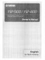
About this manual
• Make sure you read precautions in "Safety and Accesso U Information" (separate booklet) carefully before using this unit.
• This manual describes how to connect and operate this unit. For details regarding the operation of external components, refer to the
supplied owner's manual for each component.
• Operations in this manual use keys on the supplied remote control of this unit unless otherwise specified.
• :i" indicates a tip for your operation.
• An illustration of the remote control in the left pages of this manual indicates the keys to be used in two facing (left and right) pages.
• This manual is produced prior to production. Designs and specifications are subject to change in part as a result of improvements,
etc. In case of differences between the manual and the product, the product has priority.
2 En
to
connect specifically
to iPhone and has been certified by the developer to meet
Apple performance standards.
Apple is not responsible t_r the operation of this device or its compliance
with
Useful
features
Adjusting
..............................................................
volume level automatically
31
(UniVolume)
....... 31
Features
...........................................................................
4
General
operation
5
Using the sleep timer .......................................................
31
Controls
and functions
...................................................
6
Front panel .........................................................................
6
Configuring settings for each input source
(Option menu) ..............................................................
32
Front panel display .............................................................
7
Displaying
32
Rear panel ...........................................................................
Remote control ...................................................................
8
9
flow ..................................................
Using the HDMI
TM
control function ................................
the input signal information
..........................
Customizing
this unit (SET MENU) ...........................
SET MENU items ............................................................
Installation
Connections
....................................................................
10
...................................................................
12
Before connecting
components
........................................
12
Connecting
external components
Connecting
a subwoofer ...................................................
13
Connecting
the FM antenna .............................................
14
Preparing
the remote
control
.......................................
......................................
14
Installing
batteries
in the remote control ..........................
14
Operation
range of the remote control .............................
14
Changing
AUTO
OSD
SETUP
Installing
language
..............................................
(IntelliBeam)
the IntelliBeam
Using AUTO SETUP (IntelliBeam)
33
33
Basic SET MENU operation ............................................
MANUAL SETUP ...........................................................
34
34
SOUND SET MENU .......................................................
36
SOUND OUT MENU ......................................................
37
INPUT
38
MENU .................................................................
DISPLAY
System
Using
MENU ............................................................
configurations
an external
Controlling
(ADVANCED
amplifier
external
SETUP)
39
......... 40
.........................................
components
...............................
41
42
1S
.......................................
microphone
31
1S
.............................
15
...........................................................
16
Glossary
19
Specifications
................................................................
48
Saving settings .................................................................
19
List of remote
control
49
Loading
settings ...............................................................
19
Index ..............................................................................
........................................................................
21
the system
Playback
memory
Playing back sources ........................................................
21
Playing back TV sounds ...................................................
21
Playing back a player .......................................................
21
Muting
21
audio output .........................................................
Decoder
and input channel
Playback
indicators ..............................
Enjoying
CINEMA
22
DSP programs ..................................
22
23
Enjoying 2-channel sources
in surround sound .........................................................
24
Playing back 5. l-channel sources in
7.1 -channel sunound ....................................................
24
.....................................................................
25
Tuning into the desired FM station
(Frequency tuning) .......................................................
25
Registering
25
SIRIUS
FM stations and tuning in (Preset tuning).....
Satellite
Listening
Radio
to Satellite
................................
26
Radio ..............................................
26
TM
tuning
Connecting
the SiriusConnect
Activating
SIRIUS Satellite
SIRIUS Satellite Radio
Registering
Playing
tuner .............................
Radio
TM
subscription
TM
back iPodTWiPhone
TM
Radio
27
channels .............. 28
Lock .................................................
the SIRIUS Satellite
26
.......... 27
operations ..............................
SIRIUS Satellite Radio
Setting the Parental
Displaying
TM
TM
56
22
or stereo playback .............................
Changing the audio output method for surround
playback ........................................................................
FM tuning
codes ........................................
47
21
mode ..............................................................
Selecting sunound
.........................................................................
43
............................................
Using
................................
Troubleshooting
29
information
.... 30
....................................
30
TM
3En
INTRODUCTION
Wireless connection (yAired)
Digital Sound Projector
The Digital Sotmd Projector
technology
allows one slim trait to
control and steer multiple channels of sound to generate multichannel surround sound, thus eliminates the need for satellite
loudspeakers
and cabling normally associated
with conventional
surround sound systems. This unit also employs the beam modes that
let you enjoy the surround sound (5 Beam, Stereo+3 Beam, 3 Beam
for 5. l-channel audio, 5 Beam plus 2, Stereo + 3 Beam plus 2, 3
Beam for 7. l-channel
audio) and 2-channel
HDMI (High-Definition
@ HDM]
input x 4, HDMI
stereo playback.
output x 1
@ HDMI interface for standard, enhanced, or high-definition
video
(including 1080p video signal transmission)
as well as multi-channel
Deep Color video signal transmission
"x.v.Color" video signal transmission
(lip sync) information
capability
capability
High definition digital audio format signals capability
Multi-channel
Linear PCM signal capability
@ Simple and easy connections
with HDMI supported external
components
@ Functional link which enables the remote control of your TV to control
this unit (with an HDM] control-compatible
TV)
Power mode switch capability (on/standby)
Volume a@lstment
capability
TV sounds reproduce device selection capability
(this unit/TV)
AUTO SETUP (IntelliBeam)
This unit employs the automatic
sound beam and acoustic
optimization technology with the aid of the supplied IntelliBeam
microphone. You can avoid troublesome listening-based
speaker
setup and achieve highly accurate sound beam adjustments that best
match your listening environment.
Cinema
DSP
This unit employs the Cinema DSP technology developed by Ymnaha
Electronics Corp. that lets you experience movies at home with all the
original
dramatic
sound impact.
UniVolume
This unit employs the automatic volume adjustmeut function. You
can limit the volume level of the TV so that it will not increase
suddenly when whenever the contents being broadcast
commercials, etc.).
change (due to
Various digital audio decoders includes newly added HD
audio decoder, and sound technologies
@ Dolby TrueHD, Dolby Digital Plus, Dolby digital Surround
Digital, Dolby Pro Logic, Pro Logic I], Pro Logic IIx
@ DTS-HD
DTS-ES,
EX, Dolby
Master Audio, DTS-HD High Resolution Audio, DTS 96/24,
DTS, DTS-ES (discrete and matrix), DTS Neo: 6
@ Music Enhancer to improve
such as the MP3 format
@ Bass Extension
to produce
the sound quality
powerful
of compression
artifacts
bass sounds
Sophisticated FM tuner
@ 40-station
random
@ Automatic
preset tuning
and direct preset tuning
SIRIUS Satellite Radio
@ SIRIUS
Satellite
separately
@ SIRIUS Satellite
4 En
Radio tuning capability,
Radio intUrmation
using SiriusCounect
displaying
capability
kit (SWK-WI0)
(not available in some countries)
@ iPod/iPhoneinterlockfeaturetoturnon/offthisunitorswitchtheinput
source
Versatile
in conjunction
Remote
with iPod/iPhone
operations
Control
The supplied remote control comes with preset remote control codes
used to control external components connected to this unit.
Multimedia Interface)
digital audio based on HDCP
Automatic audio and video synchronization
capability
@ Wireless connection with iPod/iPhoue,
using Yamaha wireless transmitter
t_r iPod (PDX-50TX/PDX-50BC)
@ Wireless connection with subwoofer, using Yamaha wireless subwoofer
tuner, sold
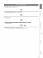
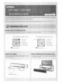
1
Install this unit and connect to other components.
"Installation" (page 10), "Connections" (page 12)
m
Run AUTO SETUP to optimize the beam and sound settings.
"AUTO SETUP (IntelliBemn)" (page 15)
z
Play back a source.
"Playback"
(page 21 ).
Change the playback method (surround/stereo), CINEMA DSP and/or beam modes settings.
"Playback mode" (page 22).
w
>
©
m
c
Configure this unit's settings and/or set remote control codes.
"Customizing this unit (SET MENU)" (page 33), "Controlling external components" (page 42).
m
m
©
>
m
z
x
SEn
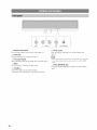
I
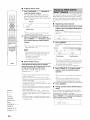
INPUT
@ Remote
control
Receives infiared
=
VOLUME
sensor
INTELLIBEAM
+
_ _ Power
signals fiom the remote control (page 14).
@ Power LED
MIC
1
(1_) key
Turns on the power of this unit or sets it to the standby mode
(page 21 ).
Lights up when the power is turned on (page 21).
• In the standby
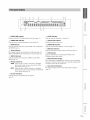
@ Front panel display
Shows information
about the operational
status of this unit (page 7).
receive infrared
signals.
mode,
this unit consumes
a small amonnt
signals from the remote control
of power
in order to
or to search for HDMI
@ INPUT
Press repeatedly
to switch between
input sources.
_5_ VOLUME +/Controls the volume level of all audio channels.
Control range: MIN (minimum),
SEn
01 to 99, MAX (maximum)
@
INTELLIBEAM
Connect the supplied
(page 15).
MIC jack
IntelliBeam
microphone
for AUTO SETUP
m
z
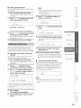
@ UNIVOLUME
indicator
Lights tip when the UniVoltune
@ CINEMA
@ SLEEP
function is turned on (page 3 l).
DSP indicator
indicator
Lights up when the sleep timer is set (page 31).
@ Volume
level indicator
Lights tip when a sound field prograu] is selected (page 22).
Displays the current voltune level.
@ HDMI indicator
@
Lights tip when the signal of the selected input source is input t]om
the HDMI IN jack(s).
Lights tip when the Music Enhancer
@ Tuner indicators
Lights tip when the bass extension
FM: Light tip when this unit is tuned into an FM station (page 25).
SIRIUS: MEMORY
flashes during the preset operation
(page 28).
(5_ SIRIUS indicators
_
@
ENHANCER
indicator
is selected
(page 37).
BASS EXT indicator
PCM indicator
m
Lights tip when this unit is reproducing
Modulation) digital audio signals.
PCM (Pulse Code
Light tip when this unit is tuned into a SIRIUS Satellite Radio
channel (page 26).
@ Multi-information
@ Wireless
Shows information with alphanumeric characters when you adjust the
parameters of this unit. CulTent input source and audio output method
are displayed when this unit is turned on.
TRNS
RECV
indicators
Lights tip when a wireless connection is established
between the Yamaha wireless subwoofer kit (SWKWI0) and this unit (page 13).
Lights up when a wireless connection is established
between the Yamaha wireless transmitter for iPod (PDX-
w
>
©
mode is turned on (page 37).
@ Input channel
c
m
display
indicators
The channel component
(page 21 ).
of the current input signal is displayed
50TX) and this unit (page 30).
@
Decoder
indicators
Light tip when the COlTesponding decoder operates
(page 21 ).
m
©
>
m
z
x
7En
!i!
i ii!iiiii!iig!ii!i!!iilJi!i!ili!ii!i!ilig!iiiiii
!ii i !iii !ii i! ii !ii ii! ii !iii i!i iii ! ii ii! ii !iii i!i iii !
\
.
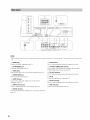
• The rear panel illustration
unit.
@
show's jacks and their names
to help you find them easily. They are not exactly the same as the ones on the actual rear panel of this
HDMI jacks
Connect
@
J
@
your HDM[ components
FM ANTENNA
@
(page 14).
jacks
Connect to the video jacks of your external components
@
SUBWOOFER
Connect
@ AUDIO
(page 12).
CONNECTOR
terminal
Connect the supplied
@ DIGITAL
jack
@
(page 26).
IN jacks
Connect to the digital audio output jacks of your external components
(page 12).
for commercial
use only.
power cable (page 12).
This is a control expansion
(page 12).
tuner (sold separately)
terminal
IR-OUT terminal
components
a SiriusConnect
terminal
_ AC_N
(page 13).
IN jacks
SIRIUS antenna
use only.
@ RS-232C
Connect to the analog audio output jacks of your external
Connect
for commercial
a Ymnaha subwoofer equipped with a SYSTEM
terminal to this unit (page 13).
@
@
SEn
SYSTEM
terminal
Use to connect
CONNECTOR
This is a control expansion
jack
your subwoofer
IR IN terminal
This is a control expansion
jack
Connect the FM antenna
@ VIDEO
(page 12).
terminal
for commercial
PRE OUT jacks
Connect your external amplifier
(page 41).
use only.
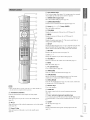
@ Input selector
keys
Use to select an input source (page 21). An input source key cmTently
selected lights up when the remote control is operated.
@ CINEMA
DSP program
Select the CINEMA
keys
DSP programs
(page 22).
@ SURROUND/STEREO
Switches between
@ Cursor
(_
surround
and stereo playback (page 22).
m
/ "_ / <1/ D) keys, ENTER
Select and adjust menu items.
@ TOP MENU
z
Displays the top menu ofa Blu-ray disc or DVD (page 42).
@ MENU
Displays the menu ofa Blu-ray disc or DVD (page 42).
@ OPTION
Displays the option menu (page 32). The remote control turns to
setting mode (@SETUP lights up).
@ SETUP
Displays the SETUP menu (page 33). Press and hold to directly enter
the LANGUAGE SETUP menu (page 15). Lights up when the
remote control is turned into the setting mode of the main unit.
w
>
©
@ RETURN
Returns to the previous menu screen (page 34).
m
@ CN _/'_
Changes the channels
@ VOLUME
of your TV/recorder
c
(page 42).
m
+/-
Increases or decreases
the volume level of this unit (page 2 l).
@ MUTE
Mutes the sound. (page 2 l).
@ TV operation
keys
Use to control your TV (page 42).
@
UNIVOLUME
Turns on or off the UniVolume
function
(page 31).
@ SUR.DECODE
Selects a decoder for surrouudj_layback
control turns to setting mode (Q)SETUP
(pa_e 24). The remote
ligl_ts up).
@ INTELLIBEAM
Enters the AUTO SETUP menu (page 16). The remote control turns
to setting mode (@SETUP lights up).
m
@ Numeric
keys
Use to enter numbers.
• When operating the keys located on the slide cover (INFO,
close the slide cover completely bet_re operation.
@ Transmission
SLEEP, etc.),
Sets remote control codes for external component
(page 42).
indicator
Lights up when infrared control
signals are being output.
@ TV (@)
Turns on the power of your TV or set it to the standby mode
(page 42).
Turns on the power of the selected component
or set it to the standby
component
operation
keys
Use to select or preset an FM station or Sirius Satellite Radio channel
or control playback of your external components (pages 25, 26 and
42).
Sets the sleep timer (page 31 ).
INFO
mode (page 42).
Power (_)
@ Tuner / external
operations
(_) SLEEP
@ AV (_)
©
©
@ CODE SET
key
Turns on the power of this unit or set it to the standby mode
(page 21 ).
Displays information
(page 32).
>
about signals currently
input to this unit
m
z
x
9 En
PREPARATION
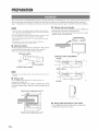
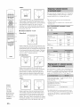
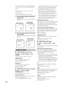
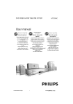
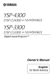
This section desclibes a suitable installation location to install this unit using a wall mount bracket, a rack, a table top stand o1 a floor stand. To
achieve desired surromld sound effects, install this unit where there are no objects such as furniture obstructing the path of sound beams
(page 11 ). Depending oll yore installation environment, connections with external components (page 12) should be done before installation.
•
Using a wall mount bracket
You can use the optional
• Make sure you leave an adequate
amount
of ventilation
space so that heat
can escape. We recommend installing this unit using a wall mount bracket, a
rack, a table top stand or a floor stand.
• Be sure to install this unit where it will not fall subject to vibrations, such as
wall mount
bracket
mount this unit on the wall in your listening
Attachment
of the wall mount bracket:
refer
supplied
with
the wall mount
recommend
•
moving
blurred or distorted,
as SPM-K30)
manual
bracket.
from an earthquake,
and where it is out of the reach of chiktren.
• When using a cathode-ray tube (CRT) TV, do not install this unit directly
above your TV.
• ]f the picture on your TV screen becomes
(such
room.
to the owner's
Wall mount bracket
we
this unit away from your TV.
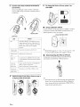
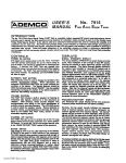
Attach the stands
Attach
you
the supplied
attach
stands
to this unit as shown
the left and right
unnecessary
if you
stands
correctly.
use the optional
wall
below.
These
mount
Make
stands
This unit
sure that
are
bracket.
Right stand (supplied)
TV
Dimensions when using SPM-K30
YSP-5100
2_1
......._and
23s
•
3ss
I
3s5
23_
(supplied)
Sc_ied)
I
_
SPM-K30
• Depending
on a rack, table top stand, or floor stand, the stands
730
4
730
_
(Option)
may not be
necessary.
•
Using a rack
You can install
commercially
It should
this
be large
above
or under
your
|
TV in a
_
YSP-4100
rack.
enough
this unit and strong
your
unit either
available
enough
to allow
adequate
to support
ventilation
the weight
of both
space
around
this unit and
TV.
When this unit is installed above your TV
o
107
(turn)
•
Using a table top stand or a floor stand
You can mount
available
When this unit is installed
lO En
under
our TV
table
both
your
top stand
TV and
o1 floor
this unit on a commercially
stand.
(ram)
to
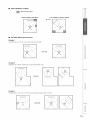
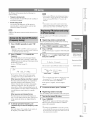
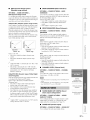
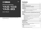
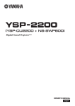
Ideal installation condition
Z
©
: Object such as furniture
c
©
Parallel installation
(with 5Beam)
Corner installation
z
(with Stereo+3Beam
40 ° to 50 °
•
For better listening environment
Example 1
Install
this
unit as close
to the exact
center
of the wall as possible.
w
>
©
m
c
m
Example 2
Install this unit so that the sound beams can be reflected offthe walls.
m
©
Example
3
Install this unit as close to the exact fiont of your normal listening position as possible.
>
m
z
x
11 En
Component video pin cable
•
Cables used for connections
The symbols on the left of cable names (such as _, ,
and ?ili)
correspond with the symbols described in "Connecting your TV and
Blu-ray disc player" (page 12) and "Connecting audio video
components"
•
(page 13).
Information on HDMI
An HDMI cable can transmit
For audio and video
both audio and vide() signals at the
same time. If your TV and other components have HDM[ jacks, use
HDMI cables for simpler and easier connections.
See also: "Using the HDM[ control function" (page 31), "INPUT
HDMI cable
MENU"
(page 38)
For audio
Audio pin cable (supplied)
Blu-ray disc
HD DVD
Dolby Digital, Dolby Digital Plus, Dolby TrueHD,
DTS, DTS-HD High Resolution Audio, DTS-HD
Master Audio, 2-channel PCM, multi-channel PCM
DVD video
Dolby
PCM
DVD audio
2-channel
Digital,
DTS, 2-channel
PCM, multi-channel
PCM, multi-channel
PCM
Optical cable (supplied)
• This unit automatically
converts
from the HDM] OUT jack.
• The HDMI of this unit supports
(HDCP),
Digital audio pin cable (supplied)
input video signals
High-Bandwidth
• We recommend
that you use an HDMI
the HDMI logo printed on it.
•
•
Content Protection
cable shorter than 5 in (16 ft) with
Priority order for audio input signals
plays back audio signals input to the DIGITAL
when "AUXI" is selected as the input source.
external components
the signals
input fiom
a single source component, this unit plays back digital audio signals
by priority. For example, if audio signals are input to the DIGITAL
IN (AUX 1) and AUDIO IN (AUX 1) jacks simultaneously, this unit
Video pin cable (supplied)
connections
Digital
When digital and analog audio signals are simtfltaneously
For video
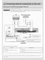
Connect
and outputs
IN (AUX 1) jack
(TV. Blu-ray disc player, etc.) to this unit. Do not plug the power supply cable into an AC wall outlet until all
are complete.
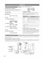
Connecting your TV and Blu-ray disc player
The following connection example shows a way to connect your TV and Blu-ray disc player by using the HDM[ jacks. When you connect them
by using the other jacks, refer to "Connecting audio and video components" (page 13). The symbols beside the cables correspond with the
symbols described
in "Cables
used for connections"
(page 12).
TV
Blu-ray disc player
"1. Pull out the cap
(if attached)
2. Check the direction
to AC wall outlet
12 En
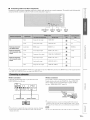
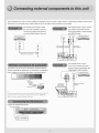
•
Connecting audio and video components
Determine
the connection
correspond
with
types
the symbols
depending
described
on the jacks
in "Cables
used
Z
available
on this unit and your
t_r connections"
(page
external
components.
The symbols
in the following
table
©
12).
c
©
z
VIDEO IN/OUT
jacks
Tv
External
component
with HDMI
Video
Composite
Audio
Analog
Audio/video
HDMI
Audio
Coaxial
Video
Component
Audio
Optical digital
video input
audio output
AUDIO IN
jacks
VIDEO
OUT
AUDIO
IN (TV)
HDMI
output
DIGITAL IN
jacks
HDMI IN
jacks
TV
HDMI 1-4
IN 1-4
output
External component
with component
video
output
digital outpnt
video output
DIGITAL
VIDEO
W
>
©
AUX2
IN (AUX 2)
m
IN (COMPONENT)
c
External component
with composite
video
output
Analog
Video
output
audio output
Composite
video output
DIGITAL
IN (AUX
AUX l
1)
AUDIO
IN (AUX
VIDEO
IN (VIDEO)
m
1)
2@'
• Video signals input t_om the VIDEO IN (VIDEO)jack
can be output not only to the VIDEO
the VIDEO IN (COMPONENT)
jacks are output to the HDMI OUT jack.
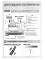
Wireline
connection
Connect
the monaural
SUBWOOFER
jack
Wireless
input jack
on your
subwoofer
OUT jack but also the HDMI
OUT jack. Video signals
input from
connection
You can make a wireless connection of your subwoofer by using the
Yamaha wireless subwoofer kit (SWK-WI0).
About SWK-WI0,
to the
on this unit.
refer to "Safety and Accessory Information"
See also: "WIRELESS
SETUP" (page 39)
SUB
(separate booklet).
m
©
__WOOFER
AUDIO
IN=
Monaural
input
System connector
V
Subwooter
}
• For proper transmission,
you need to set the group IDs of this unit and
SWK-WI0
to the same value. For the Group ID settings, refer to "Group
ID" (page 39) and "Safety
and Accessory
Information
(separate
booklet)".
>
2@'
• If the subwoofer is connected by using a system type connection,
changing
the power mode of this unit controls the power mode of the subwoofer
(Yamaha subwoofer).
• Be sure to use the product only in the country in where
m
z
it was purchased.
x
13 En
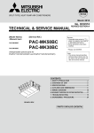
Connect the supplied FM antenna o1 your antenna to the FM ANTENNA
©
_
jack oll this unit.
(2E3 _
I
TVVOL
CH
Ante_naFiVl ANTENNA
VOLUME
__j,5,
,̧,_,
G!i3_
(5i3
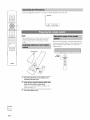
• Before installing batteries or using the remote control, make
sure that you read precautions on the remote control and
batteries in "Safety and Accessory
Information"
(separate
booklet).
The remote control transmits a directional
CD
point it toward the remote control
during operation.
Pull and hold
#
Within
6m (20ft)
_YAMAHA
Pull and hold the tab on the battery cover
and then open the cover.
Insert the two supplied batteries (R03P, UM4,
AAA) into the battery compartment.
Make sure you insert the batteries according to the
polarity markings (+/-).
3
@ENTER
@/,.
/ "_
@SETUP
14 En
infrared beam.
Use the remote control within 6 m (20 It) of this unit and
,0DES_
Close the battery cover.
sensor of this unit
Z
©
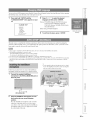
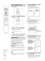
You can select an OSD language among English, German,
the following
French, Spanish,
Italian, Dutch and Russian.
Be%re operating
c
©
steps, select this unit as the video input oll your TV.
Press and hold (_}SETUP until the
"LANGUAGE SETUP" menu appears on your
TV.
2
Press (_)_
language
/ _
z
to select the desired
and then press (_)ENTER.
Choices: ENGLISH (English), DEUTSCH (German),
Frauqais (French), ESPANOL (Spanish),
", il uYi=JIUI=,P '@ ii iP'
ITALIANO
(Italian),
NEDERLANDS
(Dutch),
PyccKrffI (Russian)
-_ EN(iL :[SH
[;,ELFI'2;C:H
F t',an,;:.a s
ESF'_:i_OL,
Initial setting: ENGLISH
(English)
:[mL :[¢_HO
_sii_ the s%_em
NE:[)E:I:_:L,qN
[:,2:
3
To exit from the menu, press {L)SETUP.
iF_18/31
@_y
[ EN]ER ] ',',
E_"_i:..e_".
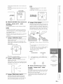
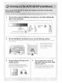
This unit creates a sound field by reflecting sound beams offthe walls of your listening room and by broadening the
cohesion of all the channels. Just as you would alTauge the speaker position of other audio systems, you need to set the
beam angle to enjoy the best possible
sound fiom this unit.
• After you have completed the AUTO SETUP procedure,
• The IntelliBeam microphone
is sensitive to heat.
be sure to disconnect
the ]ntelliBeam
w
>
©
microphone.
m
Keep the IntelliBeam
microphone
away from direct sunlight.
Do not place the IntelliBeam
microphone on top of this unit.
• You cannot
• You cannot
use the AUTO SETUP when "PREOUT"
is selected in "SOUND OUT" (page 38).
run the AUTO SETUP while playing back the iPod/iPhone
by using PDX-50TX. To run the AUTO SETUE
and then disconnect
booklet).
the iPod/iPhone
from PDX-50TX.
About
PDX-50TX,
refer to "Safety
and Accessory
Information"
c
m
stop playback
(separate
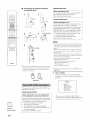
• Use the supplied cardboard microphone stand or a tripod
to >lace the IntelliBeam microphone at the same height as
our ears would be when you are seated.
Follow the procedure below to connect the IutelliBeam
microphone to this unit and place it in a proper location.
1
Connect the supplied IntelliBeam
microphone to the INTELLIBEAM MIC jack on
the front panel.
m
©
INTELLIBEAM
MIC
Place the IntelliBeam
level surface
microphone
on a flat
at your normal listening
position.
Place the hltelfiBeam
microphone
on the extended
center line of this unit and 1.8 m (6.0 it) or more
away from it. Also, make sure place the IutelliBeam
>
microphone within 1 m (3.3 it) upper or lower from
the center height of this unit.
z
x
15 En
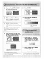
"BEAM
Assembling the supplied cardboard
microphone stand
OPTIMZ
ONLY"
(Beam optimization
only)
Use to optimize the beam angle so that the parameter
o
best matches your listening environment.
This menu takes about one minute.
"SOUND OPTIMZ ONLY"
-C_(_<>
Fit in
(Sound optimization
only)
Use to optimize the beam delay, volume, and quality so
that the parameters best match your listening
environment. You must optimize the beam angle with
"BEAM OPTIMZ ONLY" before starting "SOUND
TVVOL
CH
VOLUME
Fit in
3
4
Place horizontally
OPTIMZ ONLY". It is recommended that you should
select this optimization
feature in the following cases:
• If you have opened or closed the curtains in your
listening room before using this unit
• If you have manually set the beam angle.
This menu takes about three minutes.
(Z3 _
C_D
CE) _
,0DES_
o
_(N5
• It is normal for loud test tones to be output during the AUTO
SETUP procedure. Make sure that there are no children around
5
in the listening room while the AUTO SETUP procedure is in
progress.
• Make sure that your listening room is as quiet as possible. For
accurate measurement,
mrn off air conditioner or other devices
that make noises.
Run through
• To achieve the best results possible, vacate your listening room
until the AUTO SETUP procedure is completed so that you may
not obstruct the path of sound beams.
• If there are curtains in your listening room, we recommend
t_llowing the procedure below.
1. Open the curtains to improve sound reflection.
2. Run "BEAM Otr['IMZ ONLY".
3. Close the curtains.
_YAMAHA
4. Run "SOUND
OPTIMZ
ONLY".
• lfa subwoofer with adjustable vohnne and crossover frequency
controls is connected to this unit, turn it on, set the vohnne to
about half way and then set the crossover
nlaxinmm as shown below.
VOLUME
frequency
to the
screen while using SET MENU,
press
Press @SETUP,
CROSSOVER
The remote control keys to be used and available
operations in each step are displayed at the bottom
the screen.
O-@j
HIGH CUT
MIN
• To return to the previous
@RETURN.
of
MAX
Subwoofer
-_ ,,i"i_:HORY
,,AUT0 5ET'H.IF'
,,HAHUAt_ SETrUP
,,:i;OUt¢:, gi:T HEt4U
,,:i!;OUNi) OU°r HE!4Li
,, INF'U7 HE!.iU
oDI E:PLAY HEHU
[ .&:i.."[ ,F] _UP..'Do_,_r_
[ E:N"FE:R] ,','E:r_L,eP
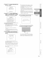
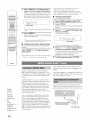
You can select one of the following AUTO SETUP types
depending
oll your purpose.
"BEAM+SOUND OPTIMZ"
(Beam
optimization
Use to optimize
quality
so that
environment.
this
and
the beam
sound
angle,
the parameters
best
It is recommended
optimization
feature
optimization)
delay,
•
•
If you make settings
for the first time
If the unit has been relocated
@RETURN
•
If your
•
If the objects
@SETUP
@INTELLIBEAM
16 En
room
in your
has been
listening
have been rearranged
This menu takes about three
and
your
listening
that you
in the following
@ENTER
listening
volume,
match
should
select
cases:
restructured
room
minutes.
(furniture,
etc.)
• You can also start the "BEAM+SOUND
procedure
OPTIMZ"
simply by hoMing down @INTELLIBEAM
more than two seconds.
In this case, proceed
to step 4.
for
Press @_ / v to select "AUTO SETUP" and
then press @ENTER.
PIIIIIIII
• If "ENVIRONMENT
CHECK IFAILED]" is displayed,
refer to "Error messages IYr AUTO SETUP" (page 18),
press @RETURN,
and then run the AUTO SETUP
procedure again.
• If "SUBWOOFER
_=LiliL _
l):_:A:='i_ <' .L, 0P'[ii=IZ
2:BEAi"i
OF"[Ti"IZ O.iL '_
:I.;':U}L_ i(: , OF"F:[H2.10HLY
c
©
is displayed
z
even though a subwoofer is connected to this unit and
turned on, check the connection and then increase the
volume level of the subwoofer and run the AUTO SETUP
procedure again.
• Depending on the environment
[ ._iCL."
[ _F] '.'UF'..'DO_a_"_
•IKhTE '_," El ",.:... "
of your listening
room, the
beam angles of front right and left and surround left and
right may be set to the same value even if "BEAM MODE
:5 BEAM"
Press @_ / "_ to select "BEAM+SOUND
OPTIMZ", "BEAM OPTIMZ ONLY" or "SOUND
OPTIMZ ONLY" and then press @ENTER.
'_iiiii
:NOT APPLICABLE"
©
is displayed
as a result.
Press @ENTER to confirm the results.
The menu screen disappears ill two seconds.
k:" !ilk'
p_'_::Pq_'q'ruiiq
;:i:. CHECK
F'].ea::-:.e Piac, e 1:,.he i"iiE: ai. 'ie.:s:!!i.
[[ _8[,'i..'6_'i:,..h_a.A'::l _"ovi
i:,.h8 i..i_'i i:,._
The }"i}X; ::_.ho_,.ilci be set.
a'i:,, es
1_,_.._e].iah_,_'i 5e.B'iL,eci,,
i"IGE!21.U_'_=[,'!_,_"iiL,
'iL..i_k_!%.B[)Obii:,. 3["i _"i.
{:ii:i:..e_" iTEH"ER'J :[:!_.Fressed,
"_i'T_""::_?bavi;...c
_ J
AUTO
Please
E;EfLiF' O}i"iF'LE-[E
_".e_,'_oue
1:.,he
Mrc
i:_'.om
[PE[U_'H]:Canc.el
Prepare to leave the room.
The best
room.
setting
Prepare
pressing
may not be done
to leave
@ENTER
if you
the room
>
©
are ill the
ill 10 seconds
• If you do not want to reflect the results, press @RETURN.
alter
ill step 5.
7
Disconnect the IntelliBeam microphone.
c
• Wait outside the room during the AUTO SETUP
procedure.
• The AUTO SETUP procedure takes about 3 minutes.
• To cancel the AUTO
press @RETURN.
SETUP procedure
after it is started,
Press @ENTER to start the AUTO SETUP
procedure and then leave the room within 10
seconds.
The measurement
_iiiii ",kiiii" ",i_b'i
(dill
results are stored ill the internal
memory of this unit until you run the AUTO SETUP
procedure again or configure the settings manually.
be';_i_"_i_"_ 1_::k:.ec.
[ RETUR!.i ] ',',
(}a h,::,e!
The
setup
AUTO
screen
SETUP
If all error
message
see "ElTor
automatically
changes
during
the
procedure.
occurs,
all error
is displayed.
messages
buzzer
sounds
For details
for AUTO
on error
SETUP"
If the AUTO SETUP procedure
rings the chimes.
©
and all error
messages,
(page
18).
is complete, this unit
!:!':,UL
!
i"iE:A_
;UR!:HENT (::OMF'L.E7
E
BEAi"I i"iOD_: _SBea_,'wF'ius2
E;LiBi,.:.:OOFE:R
_YE'i;
>
[ E:NF[ :R] ',',_;a,.,e Set..-UF',,
[REFUi;I:!.i]',',Dono'L, sa,..,e, se'L,-u_:,,
z
17 En
•
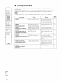
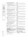
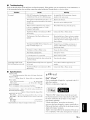
Error messages for AUTO SETUP
If an enor message
procedure below.
©
is displayed
oll your TV, check the error message list to solve the problem and then follow the
[ERROR E-1]: Press @ENTER
Other errors: Press @RETURN
to run the AUTO SETUP procedure again or @RETURN
to cancel the operation
to cancel the operation and then run the AUTO SETUP procedure again.
If the problem is difficult to be solved, configure
the settings manually in "MANUAL
TVVOL
CH
__j,5,
Remedy
CK)_Q
CE) G?D _(N)
,0DES_
CD
There is too much unwanted
your listening room.
noise in
Make sure that your listening room is as
quiet as possible. You may want to
choose certain hours during the day
when there is not much noise coming
from outside.
ERROR E-2
No MIC detected. Please check
MIC connection and re-try.
The lntelliBeam
is not
Connect the lntelliBeam
this unit firmly.
ERROR E-3
Unexpected control is detected.
Please re-try.
Some other
on this unit
ERROR E-4
Please check MIC position. MIC
should be set in front of the unit
and re-try.
The lntelliBeam microphone
placed in front ol this unit.
ERROR E-5
Please check MIC position. MIC
should be set above 1.8m/6.0ft and
The lntelliBeam microphone is not
placed in the righl distance h'om this
unit.
Make sure that the lntelliBeam
ERROR E-6
Volume level is lower than
expected. Please check MIC
position/connection
and re-try.
The lntelliBeam
Make sure that the lntelliBeam
microphone is firmly connected to this
unit and placed in a proper location. If
the problem persists, contact the nearest
authorized Yamaha service center for
assistance.
ERROR E-7
Unexpected error happened.
Please re-try.
An internal system error occurred.
connected
during
procedure
microphone
to this unil
ihe AUTO
or disconnected
SETUP
operations
were
while Ihe AUTO
was
collecl
perlormed
SETUP
ill progress.
because
the sound
is not
the sound
oulpul
cannot
by this unil
level
is ioo low.
_YAMAHA
@RETURN
@SETUP
18 En
1o
15
Do not perforl'n any other operations
while the AUTO SETUP procedure is in
progress.
Make sure that the lntelliBeam
rnicrophone
unit.
microphone
produced
microphone
procedure.
re-try.
@ENTER
page
ERROR E-1
Please test in quieter environment.
VOLUME
,̧,_,
(page 34).
See
Cause
Error message
SETUP"
15
is installed in fl'ont of this
15
microphone is installed more than 1.8 m
(6.0 ft) from the front of this unit mad
within 1 m (3.3 fl) from the center height
of this unit.
Repeat the AUTO SETUP procedure.
15
0
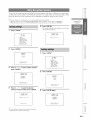
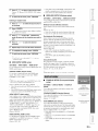
You can save the current beam and sound settings in the system memory of this unit. It is handy to save certain settings
C
©
according to the varying conditions of your listening environment. For example, if there are curtains in the path of sound
beams, the effectiveness of the sound beams will vary depending on whether the curtains are open or closed.
Z
2@t
• If there
are curtains
in your
listening
1. While
the curtains
are open,
2. While
the curtains
are closed,
room,
we
recommend
run "BEAM+SOUND
run
"SOUND
following
OPTIMZ"
OPTIMZ
ONLY"
the
below.
16) and
then
save
the settings
to "MEMORY
(page
16) and
then
save
the settings
to "MEMORY2".
5
1
procedure
(page
Press (])SETUP,
1".
Press @ENTER.
The current beam and sound settings are saved to the
selected memory number,
'/i i'iki'iiik",i'°=HUk
.._:!UT0 SE]UP
,,t'i_:)_.it.i_:il._
SETUP
,,SOUtX) SET t'iENU
,,SOUNP OU]' MEN,-'J
,, :[t.iPUT ME!.iU
° P :1:
2;F'L_W i"iEi'.iU
[ E]'ITE_':I _E)'d:.,e_"
2
Press @ENTER.
>
0
1
Press (])SETUP,
c
I )iJ'_F i:_
;;, ::,:i::ii.iF:
'=,k !
iqkt'_il
-_ ,,MEMORY
,,F!iJTO SE]UP
,,M-:6iUF!L SETUP
,,SOU_X) '.:_;ETPiE},[Li
,,SOUN[:, oLI°r i"iE[!4U
,, ][NF'UT t'iENLI
. P:[SF'LF!Y MEt.iLl
[ .£] .."[ ,_] ._iJP..'Do_,_'_
[ E]'ITER ] _E)I i:.,e_"
[A] .."i]_ ] '.'LIp..'Do_,_"_
[ EN°[ ER ] _Et"d:.,e_"
Press @ A / v to select "SAVE" and then
press @ENTER.
2
Press @ENTER.
'.,.2.:,['iL['ii.ii:'.,.'
':,Ht,.t
.:: ,[.
,
,,
b ::,t'IEi"IORY2
c.::,i"IEMORYS
ii_ik!_iiik',,'
) LOFli)
2 ) :_;i::iuE
[A].." [_F] ; (JP..'Do_,_t"_
[ E]',TE,,:.I '.'E)%e_"
[,_L].." [_F ] ._i.JP..'Dc,_,_"_
. ,.: .°.,.: .:], ,.:.",...."
Press @ _ / "_ to select the desired
memory number and then press @ENTER.
/ i i_iki_i!ik'"," '=,Ulik
©
3
Press @ENTER again.
!)!'!Et'!OF:':'
L
a)t'IEMORYi
t'IEMORY:_ Sa,..,e Ho_,d:'
c.::,i"IE]iORYS
[,¢.]..' ["_'] '.'UP..'[:,o_,_"_
[ E!.i°fER ] ::Zt%er.
>
_t
• If system
settings
number,
this unit
are already
overwrites
stored
the old
in the selected
memory
Z
settings.
19 En
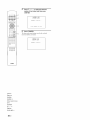
4
o
_
_
Press _ A / _ to select the memory
number to be loaded and then press
_ENTER.
(_
F'_..i:i_,h[E]'=TE[."I
5
i:.,o Load
Press _ENTER.
The beam and sound settings saved in the selected
memory number are loaded.
__j,5,
¸,,_
!,"[!_[!U_:":"
LUHL"
,00Es_
o
_YAMAHA
©Power
©AUXU2
©HDMI1
©HDMI1-4
©Input
selector
©TV
@ENTER
@A/_7
©MUTE
©VOLUME
20 En
+/-
keys
PLAYBACK
FEATURES
©
c
©
z
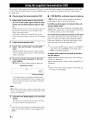
This section describes
how to playback
source input fi'om
your external components. For details on your external
components, refer to the owner's manual supplied with
each component.
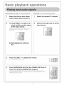
1
Press @Power (_) key to turn on this unit.
2
Turn on external components (TV, Blu-ray
disc player, etc.) connected to this unit.
3
Press one of the @Input selector keys to
select an external component as an input
source.
Input source name
1
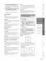
Select the player as the video input on the TV.
2
Press @HDMI1-4 or @AUXI/2 to select the
player as the input source.
For example, if the player is connected to the HDMI
IN 1jack of this unit, press (_HDMII.
3
Start playback of the player.
4
Mute the sound output on the TV.
• If your player supports the HD audio, check whether the audio
output setting on the player is set to the value which supports
HD audio output ("Auto", "Bitstream",
etc.).
• If your player does not support the HD audio, check whether
audio output setting on the player
PCM.
= = =-, =,a ,=, a
P'i_iHi
i i
• If your player
• You can change the input source name displayed on the
front panel display (page 38).
4
Start playback o! the external component
that you have selected as the input source,
or select a radio station on the tuner.
to this unit through
the
linear
the digital
connection,
check whether the audio output setting on the
player is set to digital output ("Bitstream",
"Dolby Digital",
"DTS", etc.).
• To enhance
your player
the surround sound effect, set the audio setting of
to the multi-channel
audio mode.
• You can use the supplied demonstration
DVD to check the
digital signals being inpnt from the player through the digital
connection (HDM], optical or coaxial). The 1111DiGiTAL
indicator lights up when this unit detects the digital audio signal
• FM tuning (page 25)
• Playing back iPod/iPhone (page 30)
5
is connected
is set to multi-channel
input.
Press @VOLUME +/- to adjust the volume.
Volume
=_
,=
1
Press @MUTE to mute the audio output.
2
Press @MUTE again to resume audio output.
•
Decoder indicators
.= ,.-,
Press @Power (@) key to turn this unit to the
standby mode.
1
Select the desired TV channel.
2
Press @TV to select the TV as the input
source.
3
Mute the sound output on the TV.
Depending on the input source and the selected decoder,
the indicators in the fiont panel display light up as follows:
©
>
z
21 En
iiiji
i i
i
!ilii
When PCM signals are being
input
©
When Dolby TrueHD
being input
PC[71
•
signals
are
DrlTRUE
Digital signals
rlrl EX
When Dolby Pro Logic is
selected as the surround decoder
[111PL
When Dolby Pro Logic II is
selected as the surround decoder
O0 PL]I
L_
_Surround
,_C
I_--
Front R
_--Surround
R
Depending on the channel component of the current
digital input signal, the input channel indicators in the
fiont panel display light up as follows:
....
stereo
[_
5. l-channel
are being input
_
When DTS HD High Resolution
signals are being input
[_
_
+ HD + HI RES
6. l-channel
[]
[_
[]
are
_g_cN
are
_[S
+ ES + DSCRT
When DTS ES matrix is selected
as the surround decoder
_
+ ES + MTR×
When DTS Neo:6 is selected
the surround decoder
[]
[]
+
__S
When DTS ES discrete is
selected as the surround decoder
• Extra (EX I/EX2) indicators light up when 7. l-channnel signals
recorded in a Blu-lay disc (etc.) are being input. Normally,
surround back channel signals are recorded in the extra
channels. This may vary depending on the disc.
as
+ Neo:6
_
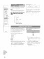
You can select the playback method
of the input source.
(surround or stereo), desired CINEMA
Use to select the playback method (SmTound or stereo).
See also: " Enjoying CINEMA DSP programs" (page 22),
"Changing the audio output method for surround
playback"
[_
[]
+ HD + MSTR
7. l-channel
_YAMAHA
[_
OOPLgx
When DTS HD Master Audio
When input
DTS 96/24 signals
being
back
Extra 1 _EX11 II!II_E)Ii_i_ii_-- Extra 2
LFE
2-channel
When Dolby Pro Logic IIx is
selected as the surround decoder
When DTS digital signals
being input
Front L --_
rlrl DiGiTAL
When Dolby Digital EX signals
are being input
signals
Center_
Surround
are
back (Auto or DTS)
Input channel indicators
HD
Dr1 DIIGJTAL PLUS
When Dolby Digital Plus signals
are being input
When Dolby
being input
• You can select an audio signal to be played
In "Decoder Mode" (page 32).
(page 23).
DSP program and decoder to enjoy playback
This unit is equipped with a Yamaha CINEMA DSP
(digital sound field processing) chip containing several
sound field programs used to enhance your playback
experience. Most of the CINEMA DSP programs are
precise digital recreations of actual acoustic environments
of t;amous concert halls, music venues, and movie theaters.
Press @SURROUND or @STEREO.
You can enjoy
@CINEMA
DSP
playback
high
and hi-fi
realistic
sound
sensation
with
stereo
with
surround
playback.
@OFF
@STEREO
@SURROUND
@ENTER
• Normal
sounds
(not sound beams) are output from the front
right and front left channels. When you play back multi-channel
sources, all signals except those from the front right and left
channels are mixed clown and output from the front right and
left channels.
• When the stereo playback
@4/D
@SETUP
22 En
and the decoder
is selected,
(page 24) become
CINEMA
ineffective.
DSP (page 22)
• When you enjoy the CINEMA DSP programs, press @
SURROUND
to select the surround playback, and then follow
the steps below.
• The CINEMA DSP programs
conditions.
are not available
Stereo playback is selected.
HD audio signals are being played
Audio signals with sampling
are being played back.
Audio
signals
in the t_llowing
back.
frequency
of higher than 96 kHz
are output from the PRE OUT jacks.
Press the desired
@CINEMA
DSP key.
The CINEMA DSP category name appears in the
flout panel display and the CINEMA DSP indicator
(page 7) lights up.
While the category
the @CINEMA
name is displayed,
Each time you press the key, program
• To turn offthe
press
DSP key repeatedly.
CINEMA
©
play, while offering movie-like
movie scenes in the game.
This program
press
@oFv.
•
Z
This program is suitable for role-playing and adventure
games. It utilizes the sound field effects for movies to
represent the depth and spatial feeling of the field during
c
©
SmTound effects in the
z
Mch Stereo
switches.
DSP program,
Game
downmixes
multi-channel
source to 2
channels and then outputs the sound fiom all speakers and
produces stereo sounds in wide range. It is ideal for
background music at parties, etc.
m
Movie (MOVIE)
z
Sci-Fi
This program clearly reproduces dialogs and special
sound effects of the latest science fiction films and lets
you feel a broad and expansive
cinematic
space.
Spectacle
You can set the number of beam output channels
audio output method.
1
Press @SETU P.
The "SET MENU" screen appears on the TV.
2
Use @ _. / "7 and @ENTER to select
"SOUND OUT MENU"- "SOUND BEAM OUT
CONFIG" - "CHANNEL OUT".
3
Press @ <1/ D to select the number of output
channels.
Choices: 5. lch, 7. lch
hfitial setting: 7. lch
This program reproduces the wide and grand environment
and lets you have added impressions on spectacular scenes
with strong visual impacts.
Adventure
This program reproduces the thrilling environment of the
latest action films and lets you feel the dynamic and
excitement
•
and
of t:ast-moving scenes.
Music (MUSIC)
Music Video
This program produces a vibrant environment and lets you
feel as if you are at an actual jazz or rock concert.
Concert
4
Press @ v
5
Press @ "_ to select the desired audio
output method.
Hall
This program
creates a rich surround
FN t_mi_g
SIRIUSSatellite
Radiio_ h_:fi:_
to select "BEAM MODE".
P_;@g_g
h_k iiP_'_d
T_v_
effect of a large
round concert hall with a great deal of presence,
emphasizing the extension of sounds, and lets you feel as
if you are seated close to the center of the stage.
6
Jazz Club
5Beam
To exit from the menu, press @SETUP.
_s@,_lff_;_h_s
Beam modes for "5.1ch"
This program recreates the acoustic environment of "The
Bottom Line", a famous jazz club in New York once and
lets you feel as if you are seated right in fiont of the stage.
•
Entertainment (ENTERTAINMENT)
Sports
This program reproduces
the energetic environment
of live
sports broadcasting, converging a commentator's
voice on
the center and broadening the overall atmosphere of the
stadium, and lets you feel as if you are seated at an actual
stadium or a ball park.
Drama
Outputs sound beams from the flout right and left, center,
m
and surround right and left channels. This mode is ideal
for enjoying surround sound effects to the fullest when
©
you watch 5. l-channel
audio discs.
Stereo+3Beam
This program stables reverberations that match a wide
range of movie genres fiom serious dramas to musicals
and comedies, and offers an optimum 3D feeling,
reproducing effects tones and background music softly but
cubically
around clear words.
Talk Show
This program reproduces excitement of live talk shows. It
enhances the ambience of gaiety while keeping the
conversations at a comfortable volume.
>
Outputs nonnal sound fiom the flout fight and left
channels and sound beams from the center and surround
right and left channels.
live recordings
m
This mode is ideal for watching
z
on a DVD.
x
23 En
3 Beam
o
This unit can decode
_7:7
Outputs sound beams flom the flont right and left and
cemer channels. For playback of multi-channel sources,
surround right and left channel sources are mixed into the
TVVOL
CH
VOLUME
2-channel
sources for 7. l-channel
or
5. l-channel playback so that you can enjoy a variety of
surround sound effects by switching the decoder.
fiont right and left channels. This mode is ideal for
enjoying movies with the whole t:amily. In addition, you
can use this mode when the listening position is close to
the backside of the wall.
•
• The decoders
are available
only when surround
(page 22) is selected.
• Available decoders vary depending
playback
on the "CHANNEL
OUT"
setting (page 23).
Press @SUR.DECODE repeatedly to switch
between decoders.
2ch _ 5ch
Beam modes for "7.1ch"
5BeamPlus2
Pro Logic
(Dolby Pro Logic)
o
Outputs sound beams flom the front right and left, center.
and surround back right and left channels. Surround right
and left channel sources are mixed into the fiont right and
left and surround back right and left channels. This mode
is ideal for enjoying surround sound effects to the fullest
when you watch 7. l-channel audio discs.
ST+3BeamPlus2
_YAMAHA
All sources
PLII
Movie
Movies
(Dolby Pro Logic I1)
Music
Game
Music
Games
Cinema
Music
Movies
Music
PLIIx
Movie
Movies
(Dolby Pro Logic
lIx)
Music
Game
Music
Games
Cinema
Music
Movies
Music
Neo:6
(DTS Neo:6)
2ch + 7ch
Neo:6
(DTS Neo:6)
Outputs normal sound flom the flout right and left
channels and sound beams from the center and surround
back right and left channels.
Surround right and left
channel sounds are output by using front right and left
channel sound and surround back right and left sound
beams. This mode is ideal for watching live recordings on
a DVD.
3 Beam
1
"'-...
@RADIO
@ENTER
This unit decodes 5. l-channel sources and then playback
them in up to 7. l-channel surround. One of the following
decoders is automatically
signals. Set "CHANNEL
selected depending on the input
OUT" to "7. l ch" (page 23).
PCM, Dolby Digital, Dolby
Digital EX, Dolby TrueHD,
Dolby Digital Plus
Dolby Pro Logic lIx Movie/
Music
DTS Digital, DTS ES matrix,
DTS HD Master Audio, DTS
HD High Resolution Audio
DTS ES matrix
DTS ES discrete
DTS ES discrete
@z&/_
@OPTION
Outputs sound beams flom the flout right and left and
center channels. For playback of multi-channel sources,
surround right and left and surround back right and left
@RETURN
@SUR.DECODE
@Numeric
keys
@TUNING
A
@MEMORY
/ V
channel sources are mixed into the fiont right and left
channels. This mode is ideal for enjoying movies with the
whole t:amily. In addition, you can use this mode when the
listening position is close to the backside
24 En
of the wall.
• Press @SUR.DECODE to switch between Dolby Pro Logic
Movie and Music. To switch to the Dolby Pro Logic Ilx Music
decoder, select "PLIIxMusic". To switch to the Dolby Pro Logic
IIx Movie decoder, select one of the decoders other than
"PLlIxMusic".
Z
©
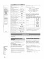
The FM tuner of this unit provides the following two
modes for tuning.
c
©
• When you press @Numeric
•
Frequency
tuning
mode
preset number
You can tune into a desired FM station by searching
specifying its fiequency.
Preset
tuning
o1
is selected.
keys during
preset tuning,
a
z
Set the tuner to the frequency
tuning mode using @TUNING
operation.
A
/v
prior to the
mode
• The reception is noisy and the sound is hard to listen,
switch to monaural mode to get better reception. In the
option menu, select "Mono" in "FM Mode" (page 32).
You can preset the fiequencies of FM stations by
registering them to specific numbers, and later just
select those numbers to tune into.
m
z
Adjust the FM antenna
reception.
connected
to this unit for the best
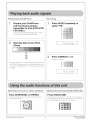
You can register up to 40 FM stations automatically
manually.
•
Registering stations automatically
The tuner automatically
1
Press @RADIO repeatedly to select "FM".
• If you select "FM"
with INPUT
on the front panel, press
signals and registers
Press @TUNING
ix / v
to specify
the
detects FM stations with strong
up to 40 stations.
1
Press @RADIO
2
Press @OPTION.
(_)RADIO on the remote control prior to step 2 so that you
can operate the procedures from step 2.
or
repeatedly
to select "FM".
The option menu (page 32) appears on the fiont panel
display.
3
frequency.
Press @ _
/ "_ to select
"Auto
Preset"
and
then press @ENTER.
The TUNED indicator on the fiont panel display
lights up when the tuner is tuned into a station. The
STEREO indicator also lights up if the program being
broadcasted is in stereo.
::!;,,
i:i:._!?o F::=
P e s e !?
See also: "FM Mode" (page 32)
This unit starts to preset FM radio stations in 5 seconds.
Lights up
_0 MEM0_
"TU_DI_RE0
i2' ivi
:..:""
:..:'' '2..'
iviLi ..,=.
Preset number
Frequency
The fiequency changes in the following manner
according to how you press @TUNING _ / v.
• You can select the preset number at which
When you press the key more than 1 second
The tuner searches the fiequency
of a station that is
detectable around the current fiequency. This is
effective when the tuner can receive strong signals
without any interference. Once the search starts,
release the key. When you keep holding the key, the
search continues even when a station is detected. This
If auto
you
press
and release
4
specify
keys to enter the frequency
the frequency,
"Preset
Complete"
©
Registering stations manually
The tuner increases or decreases the fiequency in
steps. Use this method when the tuner cannot receive
strong signals and stations are skipped during the
search.
@Numeric
station.
is complete,
To exit from the menu, press @OPTION.
You can manually
the key
To directly
preset
appears.
is useful when you want to tune in to a specific
station.
When
the preset starts
by pressing @ _/_
before pressing @ENTER.
• To cancel the operation, press @RETURN.
use
register FM stations with weak signals.
1
Tune into the desired FM station.
2
Press @MEMORY.
"Manual Preset" appears on the fiont panel display,
followed soon by the preset number to which the
station will be registered.
of the
Enter only integers. For example, if you want to set
the fiequency to 88.9 MHz, enter "889".
>
• By holding down @MEMORY t_r more than 2 seconds,
you can skip the following steps and automatically register
the selected station to an empty preset number (next to the
lastly-registered preset number).
m
z
25 En
Press @PRESET
• You can directly select a preset number by pressing
@Numeric
keys while calling a preset station.
_ / _ to select the preset
number to which the station will be registered.
When yeu select a preset number te which ne station
is registered, "Empty" appears. When you select a
o
¢P 9 ®
preset number to which any station has been already
registered, the fiequency of the station is displayed.
MEMO,Y
I", ,", ,",
-O_
C_<>
.
I....
• When you press @Numeric
keys during normal frequency
tuning, a frequency is entered. Set the tuner to the preset tuning
mode using @TUNING
A / v prior to the operation.
•
2
Preset number
O.
Press @RADIO
repeatedly
to select "FM".
Press @OPTION.
The option lllellt! (page 32) appears on the front panel
display.
• You can also specii_ya preset number using the @Numeric
keys.
TVVOL
Clearing preset stations
Use to clear the preset FM stations.
1
I
the
3
VOLUME
Press @ _
/ "7 to select
"Clear
Preset"
and
then press @ENTER.
Press @M EMO RY.
When registration
A preset station is displayed.
is complete, the front panel display
returns to the original state.
C_3i ; F::N 92 ,, !5 Nl...iz
• To cancel registration, press @RETURN or leave this unit
without any operations for about 30 seconds.
•
o
Preset station
Calling a preset station (Preset tuning)
You can call preset stations registered
manually.
automatically
• Tocancel the clearing operation, press @RETURN.
or
Press @ dx / "_" to select a preset station
be cleared,
Press @PRESET _ / W to select the desired
preset number.
to
press @ENTER.
The selected preset station is cleared. If the operation
is completed, "Cleared" appears. To clear the
multiple
• Preset numbers to which no stations are registered are skipped.
• "No Presets" is displayed if no stations are registered.
and then
5
preset stations, repeat step 4.
To exit from the menu, press @OPTION.
_YAMAHA
Family fiiendly packages are also available to restrict
channels featuring content that may be inappropriate for
children.
To listen to Satellite Radio, you'll need to connect a
SIRIUS Satellite Radio tuner (sold separately) to your
Sirius-Ready receiver. SIRIUS Satellite Radio is available
to residents of the US (except Alaska and Hawaii) and
Canada.
To subscribe
to SIRIUS,
U.S. and Canadian customers
call 1-888-539-SIRI (1-888-539-7474)
(US) or siriuscanada.ca
(Canada).
can
or visit sirius.corn
Satellite Radio delivers a variety of commercial-fiee
music fiom categories ranging fiom Pop, Rock, Country,
R&B, Dance, Jazz, Classical and many more plus
coverage of all the top professional and college sports
including play by play games fiom select leagues and
teams. Additional programming includes expert sports
talk, uncensored entertainment, comedy, l:amily
programming, local traffic and weather and news fiom
@RADIO
@ENTER
@OPTION
Once you've purchased a SIRIUS tuner you'll need to
activate it and subscribe to begin enjoying the service.
Easy to follow installation and setup instructions are
@RETURN
@Numeric keys
provided with the SIRIUS tuner. There are a variety of
programming packages available, including the option of
®o
@ENT
/
adding "The Best of XM" programming to the SIRIUS
service. The "Best of XM" service is not available to
@MEMORY
SIRIUS Canada
@PRESET _ / vv
SIRIUS Canada for any updates using the numbers and
web address below.
@TUNING A / v
26 En
operating instructions provided with the SiriusConnect
your most trusted sources.
@A/_"
@CATEGORY _
Connect the SiriusConnect tuner (sold separately) to the
SIRIUS jack on the rear panel of this unit. For details, see the
subscribers
at this time. Please check with
To AC wall outlet
tuner.
Z
• To ensure optimal reception of the SIRIUS Satellite Radio
signals, the antenna of the SiriusConnect
tuner must be placed
©
c
©
at or near a window with no obstacles in the path to the sky. The
orientation
of the antenna t_r the best reception differs
depending on the area. Refer to the instruction manuals
supplied
antenna.
with the SiriusConnect
tuner for the installation
You can mount it indoors or outdoors.
Press @RADIO
"SIRIUS".
of the
the SiriusConnect
to select
z
The SIRIUS indicator lights up on the flont panel
display and the SIRIUS Satellite Radio information
• Use the "Antenna Level" information
in the front panel display
(page 30) to check the antenna reception level and actiust the
orientation
of the antenna.
• You need to connect
outlet.
repeatedly
for the currently
panel display.
tuner to an AC wall
selected channel appears on the fiont
m
Light up
i 8 4 b.!e a !:.k.,e i..
• If"ANTENNA
ERR" appears on the front panel display, the
connection of the SiriusConnect
tuner or antenna is incorrect. In
such cases, check the connection of the SiriusConnect
tuner and
the antenna.
I
Channel
z
I
number
Channe
name
• When you select "SIRIUS" as the input source, this unit
automatically
recalls the previously selected channel.
• When yon have not activated your subscription yet, you
can only select "184" or "000".
• If a stares message or an error message appears on the
Be%re using the SIRIUS Satellite Radio feature, you need
to activate your SIRIUS Satellite Radio subscription. To
activate the subscription you need the Sirius ID which is
uniquely assigned to the SiriusConnect tuner. Sirius ID is
12-digit number and it appears on the package of the
SiriusConnect tuner, on the label of the SiriusConnect
tuner, and when you tune into the SIRIUS Satellite
channel "0" (see below).
•
front panel display,
(page 44).
"All Channel
• To select
Search
3
Contact
SIRIUS Satellite
Radio to activate
SIRIUS Satellite Radio online
Contact for activation
• Status messages appear on the front panel display during
the activation. For details, see "SIRIUS Satellite Radio"
(page 44). Once the activation
UPDATED"
appears.
is finished,
"SUB
mode"
on this
page.
by category, see "Category
on this page.
the desired
number,
channel
directly
see "Direct
number
by entering
access"
on
a channel
fiom the preset channels, see
"Calling a preset channel (Preset Search mode)"
(page 28).
• To select
• Yon can display the SIRIUS Satellite Radio int_rmation
on the front panel display (page 30).
• You can set the SIRIUS Satellite Radio preset channels
(page 28).
All Channel Search mode
Press @TUNING ^ / v repeatedly to search for
a channel within all channels.
information
URL: https://activate.siriusradio.com/
Phone: 1-888-539-SIRIUS
(1-888-539-7474)
Radio"
this page.
•
your subscription.
mode"
the channel
Press @0 and then @ENT to display the
Sirius ID of your SiriusConnect tuner.
"000 Sirius ID" and "xxxxxxxxxxxx"
("xxxxxxxxxxxx" indicates the 12-digit Sirius ID of
your SiriusConnect tuner) appears on the fiont panel
display.
Write the Sirius ID below.
ID:
Search
a channel
• To select
Press @RADIO repeatedly to select
"SIRIUS".
2
Satellite
Search for a channel by using one of the
SIRIUS Satellite Radio search modes.
• To select a channel fiom the all channel list, see
Radio
Displaying the Sirius ID of your
SiriusConnect tuner
1
see "SIRIUS
m
smEus
i2
i;£i
•.." "..' ,;.
Channel
i..i.i
.i.
II
,;, '.."
number
Channel
• You can search lUr a channel
@TUNING
,,% / v.
• Yon can skip channels
pressing
@CATEGORY
©
"i
,.".
name
quickly
to the previous
_
by holding
down
or next category
by
/ _.
>
m
z
x
27 En
Category Search mode
1
o
Press @CATEGORY _. / _ repeatedly to
select the channel category.
The CATEGORY
panel
display
When
you
category
indicator
during
select
tip on the front
lights
channel
category
the category,
You can use this feature to store up to 40 SIREJS Satellite
selection.
the first
channel
in the
is selected.
Radio channels. You can then recall any preset channel
easily by selecting the preset channel number as described
in "Calling a preset channel (Preset Search mode)" on this
page.
Light up
•
SIREUS
_0_
Registering preset channels
F' F'
Search a channel you want to set as a preset
channel in one of the SIRIUS Satellite Radio
Category
TVVOL
CH
name
search
VOLUME
• If you do not operate
Search
within
l0 seconds,
mode is automatically
modes.
Fer details, see "SIRIUS Satellite
(page 27).
the Category
Radie operations"
canceled.
sirius
__j,5,
While the CATEGORY
,̧,_
press @TUNING ^
for a channel within
indicator
lights up,
;ili ;iiiif...fj.!:, i
/ v repeatedly to search
the selected channel
2
category.
Press @MEMORY.
The MEMORY
CD
• You can search for a channel
holding
cZ) Ck_
@TUNING
^
quickly
by pressing
lights tip on the front panel
indicator
display.
and
/ v.
Light up
Currently
@6N
registered channel number
(or "- - -" if empty)
sirius
• This unit skips the channels when
Channel Search mode or Category
tUllowing cases (it is not malfimction
the channel is locked (page 29).
the channel is out of service.
you do not subscribe
•
MEMORY
this unit is in the All
Search mode in the
!
Preset
keys
the number
as "1",
"2" and
• To display the Sirius ID number
display, select channel "0".
123, press
"3".
displayed
registered.
on the front panel
• You can also select a preset number
within
@ENTER
• If the selected
channel
a few seconds
is locked, "PIN:
confirms
" appears
on the
(page 29).
• If the selected channel is not available, an advisory message
may appear. For details, see "SIRIUS Satellite Radio" (page 44)
@OPTION
@RETURN
@Numeric
Press @MEMORY.
•
Calling a preset channel (Preset Search
mode)
Prier
mode,
to selecting
you
"Registering
must
a preset
preset
preset
channel
SIRIUS
channels"
sirius
f:::'i;ili
i f...f:,.".
!:.. i
@CATEGORY
_
@MEMORY
@PRESET
,,_ / vv
@TUNING
^
/ v
/
in the Preset
channels.
Search
For details,
see
on this page.
Press @PRESET _ / W repeatedly to change the
preset channel number (1 to 40).
in "Troubleshooting".
keys
@ENT
28 En
4
the
front panel display. Enter the t_ur-digit Parental Lock code
number by using the @Numeric
keys or press @ENT to cancel
@4/_>
• If you select a preset number being used (currently
registered channel number appears next to the preset
nmnber), the current preset channel will be overwritten.
to
after you enter a one-
this unit automatically
using the @Numeric
keys.
• Instead of pressing @ENT to tune into the channel
immediately,
you can wait a few seconds until this unit confirms
the entered channel nmnber.
digit or two-digit nmnber,
entered channel number.
Press @PRESET ,_ / vv to select a preset
number to which the selected channel is
the
• To enter a one-digit or two-digit channel number, press the
@Nnmeric
keys on the remote control and then press @ENT
confirm the input number.
• If no key is pressed
number
the selected channel to an empty preset number (next to
the lastly-registered
preset number).
• To cancel the preset operation, press @RETURN.
In the All Channel Search mode or Category
search mode, press the @Numeric keys to enter
the desired three-digit channel number.
@Numeric
Channel
• By holding clown @MEMORY
l\_r more than 2 seconds,
you can skip the following steps and automatically
register
_YAMAHA
to enter
number
to the channel.
Direct number access
For example,
:L: ,.", =
I
I
of this unit):
•
Clearing preset channels
You can cleat" the assignments
Radio channels.
Press @OPTION
on the remote
The option menu for "SIRIUS"
panel display.
2
Z
of preset SIRIUS Satellite
©
• If a code number is already registered
and you enter the different
number. 'Wrong"
appears and the screen returns to step 3. Enter
the correct code nLimber.
control.
• If you fl_rget the Parental lock code or want
using "SIRIUS PIN" (page 41 ).
appears on the fiont
to change
Press @ _ / D to select the category
channel
Press @ _ / "7 repeatedly to select "Clear
Preset" and then press @ENTER.
c
©
it. reset it
z
of a
you want to lock.
smEus
m
Ci:iT;; Roc.k
s_mus
i
Preset number
Channel
7
name
Press
@ A / "_ to select
a channel
you want
z
to lock.
• To cancel the clearing operation, press @RETURN.
Press @ _, / "7 to select the preset number
to reset and then press @ENTER.
The selected preset number is reset. To reset another
preset number, repeat step 3.
4
smEus
i;ili
i 5 ::C i s £ e wi.,,.::i
8
Press @ENTER
to lock the selected
You can toggle channel
channel.
lock and unlock as you press
@ENTER.
To exit from the menu, press @OPTION.
smEus
0i5:L..0ci.{£
You can use the Parental Lock feature to limit the access
to the desired SIRIUS Satellite channels. This unit
g
automatically skips the locked channels when this unit is
in the All Channel Search mode or Categot 7 Search mode.
•
Setting the code number and locking
channels
desired
10
1
Press @OPTION
to be locked.
on the remote
The option menu for "SIRIUS"
panel display.
2
Press @ _
3
@ _
to select
a digit to edit) and
/ "_" (to select a number)
desired
4-digit
control.
and then press @ENTER.
Use @ <] / D (to select
To exit from the menu,
press @OPTION.
ID".
appears on the fiont
/ "7 repeatedly
"ParentalLock"
8 to lock all the
channels.
This unit is tuned into the last channel you select in
the "Parental Lock" screen. If the channel is locked,
this unit is tuned into "184 Weather" or "000 Sirius
Use this feature to set the Parental Lock code number
(PIN) and select the channels
Repeat steps 6 through
-, cH
•
Tuning into the locked channels
Tune into the channel with direct number access (page 28)
or Preset Search mode (page 28). When you tune into the
locked channel, "LOCKED CH" appears on the fiont
panel display, followed by the following message. Enter
the Parental lock code by using the @Numeric keys. To
cancel this operation, press @ENT.
to enter the
code number.
It" you have entered a code number before, enter the
same code nunlbeE
m
s_mus
Hew F:Zi'.i;;i;iiii;iiii;iiii;ili
©
• If an incorrect number is entered, "Wrong" appears on the front
panel display and this unit is tuned into the previously selected
channel.
The entered code number is needed for tuning in the
channel or unlocking the channel. Write it down below.
Code number:
4
Press @ENTER.
The confirmation
5
Press @ENTER
screen appears.
again to confirm
the code
>
number.
m
z
x
29 En
Display example (Fii..i:..:i.:i;'i..
" :iil;,:::,i._';;i)
sirius
Use this feature to display the SIRIUS Satellite Radio
infommtion
oll the fiont panel display.
• If the SIRIUS
• If a status message or an error message appears on the t_ont
panel display, see "SIRIUS Satellite Radio" (page 44).
signals,
Press @INFO repeatedly to toggle the following
SIRIUS Satellite Radio information display
modes.
By using the Yamaha wireless transmitterfor iPod (PDX50TX/PDX-50BC), you can use the iPod/iPhone as a
remote
control
and
See
playback
of your
iPod/iPhone
on
iPod/iPhone
- iPhone
"ACQUIRING"
• When an information
in where it was
iPod
• You cannot run the AUTO SETUP while playing back the iPod/
iPhone by using PDX-50TX. To run the AUTO SETUR stop
playback
50TX.
@INFO
30 En
"--'
appears.
Connect your iPod/iPhone and PDX-50TX, and
then start playback.
and then disconnect
of your iPod/iPhone,
the iPod/iPhone
from PDX-
When this unit is in the standby
mode,
this unit
as the input
this unit turns on
and selects "iPod" as the input source.
• You can also select the input source with @iPod.
• To adjust the volume level, use the volume control
iPod/iPhone or @VOLUME
+_ on this unit.
• This unit automatically
turns to the standby
t_llowing conditions.
The iPod/iPhone
is disconnected
The iPod/iPhone
_SLEEP
on the front panel display.
automatically
operates as follows.
When this unit is on, this unit selects "iPod"
source.
purchased.
• This unit does not support iPod (4th generation or before),
without Dock connector, iPod photo and iPod mini.
+/-
appears
is unavailable,
• When you start playback
3G
• Be sure to use the product only in the country
@UNIVOLUME
a character
models.
iPod touch
iPod nano
iPhone
@VOLUME
contains
About
• This unit supports the following
iPod 5th generation
iPod classic
@iPod
Radio information
PDX-50TX/PDX-50BC, refer to "Safety
Accessory Information" (separate booklet).
also: "iPod Interlock"
(page 39)
this unit.
_YAMAHA
and enjoy
Satellite
that cannot be recognized by this unit, the character will be
displayed with a space.
• When the antenna of the SirinsConnect
tuner cannot receive the
mode in the
from PDX-50TX.
is turned into sleep mode.
on the
Z
©
Registering HDMI components to TV
1
Select this unit as the input source of the TV.
2
Turn on the HDMI control device (Blu-ray disc
or DVD player) connected to this unit.
3
Select the HDMI control device (Blu-ray disc
or DVD player) as the input source of this unit
to check the video input.
c
©
z
This fuuctiou adjusts the volume level of the TV so that it
will uot iucrease suddeuly wheu wheuever the couteuts
beiug broadcast
chauge (due to commercials,
etc.).
Press @UNIVOLUME.
The UNIVOLUME
iudicator
lights
up ou the fi'out pauel
m
display.
z
• To turn off the UniVolmne
again.
• We recommend
playback
turning
the remote
OUT
•
• In case the HDMI control function does not work. check the
followings. Alsn, turning off (unplug) and turning on (ping) the TV
may be effective.
"HDMI (ONTROL" is set to "ON" on this unit (page 39).
The HDMI control function is enables on the TV.
If you changed the connection method or connected components.
repeat steps 1-3.
press (_)UNIVOLUME
off the UniVolmne
function
during
of music.
Yuu can operate
control
function,
the following
control
jack
of this
functions
TV when
supported)
function
Turning
of your
of this
the TV
is connected
unit with
(HDMI
Use this feature
to the HDM[
standby
unit.
on this unit or to the standby
(conjunction
with
TV)
•
Adjusting
•
Selecting
the volume
a device
reproduce
to
TV sounds
this unit or
TV)
-&
• Even if your TV supports the HDMI control fimction, some
fimctions may not be available. For details, refer to the manual
supplied with your TV.
• If you connect this unit and Blu-ray disc player or DVD player
(HDMI control function supported) with HDMI, you can also
control those devices with the HDMI control fimction. For
details,
refer to the manual
supplied
Tu use this function,
function
and
register
• For some HDMI
TV, DVD player/recorder
you
need
to set HDMI
the HDM[
components,
control function. Registering
required in this case.
a specified
set this
period
unit to the
of time.
Press @SLEEP repeatedly to set the interval
for the sleep timer.
The SLEEP indicator (page 7) flashes in the fiont
panel display while switching the interval for the
sleep timer.
---+5.i aai:::. .i.;?._;5
,;,,i n,=
5.i a-,..:::. 5'.._;5
mi n=
.5.i,.:-:,a,,
.... ,"50.,,_.,,,_,,
components
components
C' 7 ,....,...._.... 'TE:._ _.....;_,...
and Blu-ray
control
to the TV.
you only need to set the HDMI
HDMI
to automatically
after
with each device.
• We suggest that you use products (TM Blu-ray disc/DVD
player, etc.) from the same manufacturer.
• The HDMI control-compatible
components
include Panasonic
VIERA Link compatible
disc player.
1
mode
Wait for a few seconds without operating this
unit to confirm the setting for the sleep timer.
The SLEEP indicator lights up in the fiunt panel
display, indicating that the sleep timer is activated.
to TV is not
Setting the HDMI control function
• If this unit is set to the standby
setting is canceled.
mode,
m
the sleep timer
©
1
Turn on all devices connected to this unit
with HDMI.
2
Enable the HDMI control function on each
device.
For this unit, set "HDMI CONTROL" to "ON"
(page 39).
For external devices, refer to the manual supplied
with each device.
3
Turn off the TV and then turn on it again.
>
m
z
31 En
o
You can configure various settings for each input source
(TV. AUX 1/2, HDMII-4, iPod, FM and SIRIUS).
Available menu items vary depending
input source.
-C_<_<>
1
Press @Input
desired
2
selector
oll the selected
keys to select the
input source.
Press @OPTION.
VOLUME
Clear Preset (Clear
__j,5,
,̧,_
c_ _
cg)
3
4
Radio
(page 29).
r,,,e T l.":,".r,,,
Press @ _, / v
to select
the desired
menu
item and then press @ENTER.
cg) (ED _(_)
,00Es_
CD
preset station)
ParentalLock
(Parental lock)
Use to limit access to the desired SIRIUS Satellite
channels
i ,..t..io i
preset)
Use to clear the preset FM stations (page 26) or preset
SIRIUS Satellite Radio channels (page 29).
input source appears oll the flout panel display.
CH
Auto Preset (Automatic
Use to automatically detect FM radio stations and registers
them as preset stations (page 25).
The first item of the option menu for the selected
XVVOL
FM Mode (FM receiving mode)
Use to set the FM broadcasting receiving mode.
Choices: Stereo*, Mono
Select Stereo to receive in stereo mode by priority.
• Select Mono to receive in monaural mode.
Use to display information of the sampling flequency,
video signal type, and resolution for each input source on
Press @ 4 / D to select the desired
setting
the fiont panel display.
and then press @ENTER.
1
5
To exit from
•
Option
The following
source.
the menu, press @OPTION.
menu
HDMI1-4)
for each input
M i .i _"i'i _"_ "', 5) r,'_i=' i 'i _"_'..i
Decoder
Mode
Sampling
TV
Volume
Trim
Decoder
Mode
The sampling
conversion.
AUXIn2
Volmne
Decoder
Trim
Mode
Video signal (Video Signal In)
Signal type and resolution of video input signal.
FM
Volume
Trim
FM
Mode
Auto
Preset
SIRIUS
Volmne
Clear
Parental
Trim
Preset
Lock
Clear
Preset
Volume
Trim
Details of the menu items are as follows. The
configuration will be reflected to the input source
currently selected.
• The initial settings are marked with "*".
Volume Trim (Volume
trim)
Use to reduce any change in vohune when switching input
sources by correcting volume differences between input
sources.
@4/_>
@OPTION
@INFO
32 En
Press @INFO repeatedly to change items to
be displayed.
Trim
iPod
@ENTER
and
Volmne
_YAMAHA
@Input selector keys
(TV, AUXI/2,
and then press @INFO.
items
menu items are provided
2
HDMI 1-4
Select an input source
Adjustable range: -6.0dB
hfitial setting: 0.0dB
to +6.0dB
(in 0.5 dB steps)
Decoder Mode (Decoder mode)
Use to select DTS digital audio signals for reproduction.
Choices: Auto*, DTS
• Select Auto to automatically select audio input signals.
• Select DTS to selects DTS signals only. Other input
signals are not reproduced.
frequency
fiequency
(Audio
Sampling)
per second in analog- to-digital
SETTINGS
Z
©
c
©
z
You can manually configure
various settings for this unit in "SET MENU".
m
MEMORY
LOAD
Loads the beam
and sound settings
saved in the
19
z
menlory,
SAVE
Saves the current
beam and sound settings
to the
19
menlory,
AUTO SETUP
BEAM+SOUND
OPTIMZ
Optimizes the beam and sound settings
automatically.
16
BEAM
ONLY
Optimizes
the beam settings
16
Optimizes
the sound settings
OPTIMZ
SOUND
MANUAL
SETUP
OPTIMZ
SETTING
ONLY
PARAMETERS
At[justs the listening
automatically.
automatically.
room and listening
16
position
34
settings.
SOUND
SET MENU
BEAM
ADJUSTMENT
IMAGE
LOCATION
TONE
CONTROL
Adjusts
the various
Actiusts the sound position
channels.
Adjusts
AUDIO
SET
DELAY
DRC:Dynamic
INPUT
OUT MENU
MENU
MENU
the subwoofer
settings.
the dynamic
36
between
video signals
range.
36
37
Selects
the bass sound extension.
37
MUSIC
Selects
the compressed
37
ENHANCER
LEVEL
SOUND
BEAM
SOUND
OUT
INPUT
OUT CONFIG
Adjusts
the volume
audio enhancer.
of each channel.
the sound beam output settings.
37
Configures
the audio signal output settings.
37
Assigns jacks according
INPUT
RENAME
Renames
HDMI
SETUP
Configures
the HDMI
Configures
the wireless
Configures
the front panel display
E DISPLAY
OSD
SETUP
SETUP
SETUP
LANGUAGE
UNIT SETUP
Configures
SETUP
37
Configures
ASSIGNMENT
WIRELESS
DISPLAY
36
BASS EXTENSION
CHANNEL
SOUND
or low-
35
sound.
Configures
Adjusts
35
of the front right and left
Adjusts delay in output tinting
and audio signals.
Range Control
settings.
the output level of high-frequency
frequency
SUBWOOFER
sound beam
the displayed
to the component
input source.
settings.
to be used.
38
38
39
settings.
39
settings.
the OSD settings.
Changes
the language
used in the OSD.
Changes
the display unit of measurement.
39
40
40
40
>
m
z
x
33 En
In "SETTING PARAMETERS 113", configure
"INSTALLED POSITION".
1
o
Select
Press @SETUP.
'=,_ i
FLAT
TO
ANGLE
TO WALL
position
WALL*
of this
unit.
(parallel
OR CORNER
to wall),
(angle
to wall or
corner)
IH_NIi
-_ ,,i"!EHOR*?
,,_:IU°[O _;E"i UP
,,i"I_:!DiU_:IL.._:rLi_'
,,:i_;Oi.JNDLE r i"iENU
-O_
C_<>
the installed
Choices:
ANGLE TO WALL OR
CORNER
FLAT TO WALL
/
,, :[DiPLi°[ HEi'.iLi
.:E?,TE 2, "E ",.:....".
WVOL
CH
WLUME
__j,5,
,̧,_,
cg) _
CiD
2
Press @ _ / _ to select the desired menu
and then press @ENTER.
• If you change this setting "BEAM
changes autonaatically
(page 23).
'::"!'!fi!,!UfiL
' ZTT'
-_ :[ ::,:I_;E°[
7 :[NG F'gRgH! 7rER5
::::'..'g"? '_ .:i[:, :i:L".[:. .°
::!;::,i Hg(_iE: LOCFCF:[OH
(2D G?D _(N)
,00Es_
CD
menu,
setting
Configure "INSTALLED HEIGHT".
Specify the installed height of this unit.
Control range: 0.0 m to 3.0 m (0.0 ft to 10.0 It)
Initial setting: 1.0 m (3.5 It)
[.&[].." [_F[] ',',UP..'Do_,_"_
[ ELTE,.: '] '_E¢,.:.....
¢
• To return to the previous
MODE"
press @RETURN.
Press @ /', / "7 / <_/ _ and @ENTER to
configure each parameter.
• The initial settings
are marked
0.0 to 3.0 m
with "*".
.0 ft to 10.0 ft)
_YAMAHA
• The menu screen disappears if one of the @Input selector
keys is pressed while the SET MENU is being configured.
• Press (_) _
4
To exit from the menu, press @SETUP.
to the next page.
In "SETTING PARAMETERS 213", configure
the listening room settings.
Specify the length and width of the listening room.
Control range: 2.0 m to 12.0 m (6.5 ft to 40.0 It)
Use this menu to manually adjust the parameters related to
the sound beam output. To fine-adjust parameters
configured by AUTO SETUR use "BEAM
ADJUSTMENT"
and "IMAGE LOCATION".
•
to proceed
SETTING PARAMETERS (Setting
parameters)
When this unit is
installed parallel to wall,
specify the width of the
listening room and the
distance between this
unit and rear wall.
SET MENU _ MANUAL SETUP _ SETTING
PARAMETERS
Use to set the position
and the distance
@Input
selector
@ENTER
keys
of this
• If you make a_tiustments
"BEAM ADJUSTMENT"
adjusted.
of this unit
unit fiom
in your
listening
the listening
room
position.
in "SETTING PARAMETERS",
parameters are automatically
the
• If you make adjustments
in "SETTING PARAMETERS",
beam optimization
settings made in the AUTO SETUP
procedure will be lost.
the
When this unit is
installed at the corner of
the room, specify the
width of length of the
listening room.
@ _,/'_/4/1>
@_
@RETURN
@SETUP
In "SETTING
PARAMETERS
the distance
settings.
313", configure
Specify the distance between the listening position
and this unit. When this unit is installed parallel to
wall, you also need to specify the distance
the listening position and left wall.
34 En
between
Z
Control range (fiom this unit): 1.8 m to 9.0 m (6.0 ft
to 30.0 fl)
• Configure this setting only when you have adjusted
"HORIZONTAL
ANGLE".
Control range (from left wall): 0.6 m to l 1.4 m (2.0 fl
to 38.0 fl)
Control
range:
0.3 m to 24.0
m (1.0 ft to 80.0
©
c
©
It)
FLAT TO WALL
z
0.6 to 11.4 m
(2.0 to 38.0 ft)
1.8 to 9.0 m
(6.0 to 30.0 ft)
•
The length of each
arrow indicates the
beam travel length.
z
BEAM ADJUSTMENT (Beam adjustment)
SET MENU _
MANUAL
SETUP
_
m
Configure
BEAM
"FOCAL
LENGTH".
Adjust the distance fiom the fiont of this unit to the
focal point of output for each channel to achieve an
ADJUSTMENT
Use to manually adjust the various sotmd beam settings.
expansive feeling for each channel. Adjust toward (minus) to move the focus outward (widen the sweet
spot) and adjust toward + (plus) to move the focus
• The "BEAM ADJUSTMENT"
parameters are automatically
adjusted (except "Center" in "FOCAL LENGTH")
if you run
the AUTO SETUP (page 15) or if you configure "SETTING
toward the normal position
PARAMETERS"
(page 34).
• Depending on the beam mode settings
positions may not be available
is displayed.
Configure
"HORIZONTAL
In this case, "
the sweet spot).
Focal
length -
(page 23), some channel
for selection.
(nanow
w
>
©
point
"
m
ANGLE".
Sweet
spot
Adjust the horizontal angle (51sotmd beams for each
channel using test tones.
I
Adjust toward L (left) to move the direction of the
output to the left and adjust toward R (right) to move
Control range: -1.0 m to +13.0 m (-3.5 ft to +43.5 ft)
it to the right.
Control range: L90 ° to R90 °
(-)
(+)
c
• We recommend that you use the initial setting (-0.5 m or1.5 ft) for "Center".
• The width of the sweet spot becomes slightly wider than
the width of this unit if you run the AUTO SETUP
(page 15) or if you configure "SETTING
PARAMETERS" (page 34).
(+)
(-)
Example
Front left channel
• Press (_) _
Configure
to switch
Center channel
the channels.
"VERTICAL
ANGLE".
Adjust the vertical angle (51sound beams for each
channel using test tones.
Adjust toward - (minus) to move the angle downward
and adjust toward + (plus) to move the angle upward.
Control range: -45 ° to +45 °
•
IMAGE LOCATION (Image location)
SET MENU _ MANUAL
<)
SETUP
_ IMAGE
LOCATION
Use to adjust the direction
.
_ (+)
"_(_)
fiom which the fiont left and
right channel sound is heard so that each sound can be
heard closer to the center channel.
Use this feature to redirect audio signals if the sound
Configure
"BEAM
Adjust the distance
TRAVEL
LENGTH".
that sound beams travel after
coming fiom the fiont left and right channels
unnatural.
>
seems
m
z
being output and reflected offthe wall until they
anive at the listening position so that all sounds can
anive at the listening position
x
at the same time.
35 En
You can adjust this parameter only when "5BeamPlus2",
"5 Beam" or "3 Beam" is selected in "BEAM MODE"
Select SUBWOOFER
if you connect a subwoofer with
a subwoofer cable. LFE and low-fiequeucy
signals
fiom other channels are directed to the subwoofer.
(page 23).
Select FRONT
• To adiust the volmne of each channel, see "CHANNEL
LEVEL" (page 37)
Choices:
•
OFF*, ON
Select "ON" to configure
do not use a subwoofer. They are directed to the
subwoofer automatically when a wireless connection
between a subwoofer and this unit is established
the sound direction.
Adjust the image location for the front left
channel (LEFT).
The higher the percentage, the louder the output fiom
the center
With the front left
channel adjusted
Without adjustment
OR AUTO if you do not use a
subwoofer or connect a subwoofer by wireless. LFE
and low-fiequeucy
signals fiom other channels are
directed to the fiout right and left channels when you
properly. If the wireless connection is cut off. they are
directed to the fiout channels automatically.
CROSS
OVER (Crossover)
When "BASS OUT" is set to "SUBWOOFER",
you can
use this feature to select a crossover (cutoff) fiequeucy for
all low-fiequeucy
signals. All fiequeucies below the
selected fiequeucy will be sent to the subwoofer
Choices: 80Hz, 100Hz, 120Hz*
LFE LEVEL (Low-frequency
effect
level)
Adjust the output level of the low-frequency
Adjust the image location for the front right
channel (RIGHT).
The higher the percentage, the louder the output fiom
the center
With the front right
channel adjusted
Without adjustment
position.
effect (LFE)
channel according to the capacity of your subwoofer. This
setting is effective only when this unit decodes Dolby
Digital or DTS signals.
Choices: -20 dB to 0 dB*
DISTANCE
(Distance)
Adjust the distance of the subwoofer fiom the listening
position.
Choices: 0.3 m to 15.0 m (1.0 ft to 50.0 It)
Initial setting: 3.0 m (10.0 It)
•
AUDIO DELAY (Audio delay)
SET MENU _ SOUND SET MENU _ AUDIO
DELAY
Use to adjust delay in output timing between video signals
and audio signals.
AUTO LIP SYNC (Automatic
•
TONE CONTROL (Tone control)
SET MENU _
SOUND
SET MENU
_ TONE
•
CONTROL
Use to adjust the tonal quality of sound beams.
•
TREBLE
(Treble)
Use to adjust the high-fiequeucy
Choices: -10.0 dB to +10.0 dB
lipsync)
Select whether to automatically
adjust the audio output
delay when a TV that supports the automatic lipsyuc is
connected to the HDMI OUT jack of this unit.
Choices: ON*, OFF
Select ON if the TV connected to the HDMI OUT jack
of this unit supports the automatic lipsyuc. The audio
output delay is automatically adjusted.
Select OFF if the TV connected to the HDMI OUT
jack of this unit does not support the automatic lipsyuc
or you want to disable the automatic lipsyuc. You can
manually adjust the audio output delay in "HDMI".
response.
Initial setting: 0.0 dB
TV
BASS (Bass)
Adjust the audio output delay applied to signals input
Use to adjust the low-fi'equeucy response.
Choices: -10.0 dB to +10.0 dB
fiom the TV jacks.
Control range: 0 msec* to 400 msec
Initial setting: 0.0 dB
HDMI
•
SUBWOOFER SET (Subwoofer settings)
SET MENU _
SOUND
SUBWOOFER
SET
Use to configure
the subwoofer
BASS OUT (Bass
SET MENU
settings.
out)
Select where to output low-fiequeucy
effect (LFE) and
low-frequency (bass) signals.
Choices: SUBWOOFER,
FRONT OR AUTO*
36 En
Manually
adjust the audio output delay applied to signals
input fiom the HDM[ IN jacks. This setting is effective
only when "AUTO LIP SYNC" is set to "OFF"
Control range: 0 msec to 400 msec
Initial setting: 30msec
AUXI/2
Adjust the audio output delay applied to signals input
fi'om the AUX 1/2 jacks.
Control range: 0 msec to 400 msec
Initial setting: 30msec
•
DRC:Dynamic Range Control
(Dynamic range control)
•
BASS EXTENSION (Bass extension)
SET MENU _ SOUND
SET MENU _ SOUND SET MENU
EXTENSION
DRC:Dynamic Range Control
Use to adjust the dynamic range compression. Dynamic
range is the difference between the smallest sound that can
be heard above the noise of the equipment and the biggest
sound that can be heard without distortion.
Use to turn on or offthe
Adaptive
DRC (Adaptive
Select whether to automatically
dynamic
function is enabled,
in conjunction with the volume level. When this function
is enabled, the dynamic range is adjusted as follows.
When the volume level is low: Narrow the dynamic range.
Loud sound is played back softer, and soft sound which is
hard to be listened to is played back louder.
When the volume level is high: Widen the dynamic range.
From soft sound to loud sound, source sound is played
back without adjusting volume.
BASS
bass sound extension.
the BASS EXT indicator
©
c
©
When this
lights up on
z
the fiont panel display (page 7).
Choices: OFK MID*, DEEP
•
Select OFF to output bass sounds without change.
•
Select MID to output moderately-enhanced
sounds.
•
Select DEEP to output deep bass sounds.
range control)
adjust the dynamic range
SET MENU _
Z
•
bass
m
MUSIC ENHANCER (Music Enhancer)
SET MENU _ SOUND
SET MENU _
z
MUSIC
ENHANCER
Use to turn on or off the compressed audio enhancer.
When this timction is enabled, the ENHANCER indicator
lights up on the front panel display (page 7).
AUXI/2
Select whether to apply the compressed
for playback of AUXI/2 input sources.
Choices: ON, OFF*
i
•
off
Input level
Volume : low
Choices:
•
•
•
•
•
Input level
Select ON to enable the compressed audio enhancer for
playback of AUX 1/2 input sources.
Select OFF to disable the compressed audio enhancer
for playback
Volume : high
of AUX 1/2 input sources.
m
Select On to enable the adaptive dynamic range
control.
Select Off to disable the adaptive dynamic range
control.
Select whether to apply the compressed
iPod/iPhone playback.
Choices: ON*, OFF
audio enhancer to
•
Select ON to enable the compressed
iPod/iPhone playback.
audio enhancer
"Dolby/DTS DRC" is automatically set to "Max" when
"Off" is selected.
This setting is automatically set to "Ofl"' when the
UniVolume function is turned on while this setting is
automatically set to "On" when the UniVolume
function is turned off
•
Select OFF to disable the compressed
for iPod/iPhone playback.
DRC (Dynamic
w
>
©
iPod
On*, Off
Dolby/DTS
range of Dolby Digital
and DTS signals)
Select the amount of dynamic range applied when this unit
is decoding Dolby Digital and DTS signals
Choices: Max* (Maximum), Standard, Min/Auto
(Minimum/Auto)
•
•
•
Select Max to output sound without adjusting the
dynamic range of the input signals.
Select Standard to set the standard dynamic range
•
•
recommended for regular home use.
Select Min/Auto to set the dynamic range suitable for
low volume or a quiet environment, such as at night,
for bitstream signals except for Dolby TmeHD signals
(Min) or adjust the dynamic range for Dolby TrueHD
signals based on input signal information
(Auto).
•
"Adaptive DRC" is automatically set to "O114' when the
settings other than "Max" is selected.
c
m
for
audio enhancer
CHANNEL LEVEL (Channel level)
SET MENU _ SOUND SET MENU _ CHANNEL
LEVEL
Use to adjust the volume of each channel with test tones.
Control range: -10.0 dB to +10.0 dB
• Adjustable
channels
vary depending
on the "CHANNEL
OUT"
setting.
• "Surround Back R" and "Surround Back L" are not adjustable
when "SOUND OUT" is set to "SPEAKER".
•
SOUND BEAM OUT CONFIG (Sound
beam output configuration)
SET MENU _ SOUND
OUT MENU _ SOUND
BEAM OUT CONFIG
Use to configure
•
audio enhancer
the number of output channels
or audio
output method. For details, see "Changing the audio
output method for surround playback" (page 23).
•
SOUND OUT (Sound output)
>
SET MENU _ SOUND OUT MENU _ SOUND OUT
m
Use to configure the audio signal output settings.
z
x
37 En
SOUND
OUT (Sound output
redirection)
Use to redirect the output of audio signals. Audio output
of all the channels switches simultaneously.
Choices: SPEAKER*, PRE OUT
©
•
•
Select SPEAKER to output sounds fiom this unit.
Select PRE OUT to output audio signals fiom the PRE
OUT jacks of this unit. You also need to configure the
parameters fiom "BASS OUT" to "LFE Level"
described below.
• The parameters from "BASS OUT" to "LFE Level" are settings
for the PRE OUT jacks when they are selected as audio outpnt
jacks.
BASS OUT (Bass
XVVOL
CH
__j,5,
VOLUME
,̧,_,
sound
output
redirection)
Use to redirect the output of bass sounds. The settings
under "BASS OUT" are for the PRE OUT jacks.
Choices: SUBWOOFER,
FRONT*
•
Select SUBWOOFER
subwoofel:
•
Select FRONT
to output bass sounds fiom the
CD
• The input already
Front SP Size (Front
speaker
size for PRE OUT)
woofer is smaller than 16 cm. Low-fiequeucy
parts of
fiout right and left channel signals are output fiom the
subwoofel:
Center SP Size (Center
selected
in "AUDIO2"
the input selected in "AUDIO2"
and then reconfigure.
is not displayed.
change
"AUDIO2"
To set
parameter,
AUDIO2
Select the key to which the AUDIO IN (AUX 1) jacks are
assigned.
Choices: AUXI*, AUX2, HDMII, HDMI2, HDMI3,
HDMI4,
TV
• The input already
selected
in "AUDIO
the input selected in "AUDIO
and then reconfigure.
l" is not displayed.
1" change
To set
"AUDIO I" parameter,
OPTICAL1
Select the size of external fiout speakers.
Choices: Small, Large*
• Select Small if the diameter of the fiout speaker's
_YAMAHA
Select the key to which the AUDIO IN (TV) jacks are
assigned.
Choices: TV*, AUX 1, AUX2, HDMII, HDMI2, HDMI3,
HDMI4
to output bass sounds fiom the external
fiout right and left speakers.
,0DES_
AUDIO1
speaker
Select the key to which the DIGITAL IN (TV) jack is
assigned.
Choices: TV*, AUX 1, AUX2, HDMII, HDMI2, HDMI3,
HDMI4
• The input already
selected
in "OPTICAL2"
or "COAX"
is not
displayed. To set the input selected in one of these parameters,
change the corresponding
parameter, and then reconfigure.
size for PRE
OUT)
OPTICAL2
Select the size of external center speakers.
Choices: None, Small*
Select the key to which the DIGITAL IN (AUX 1)jack
•
•
Select None if no center speaker is used. Center
channel signals are mixed into the fiout fight and left
speakers.
Select Small if a center speaker is used. Low-fiequeucy
parts of center channel signals are output fiom the
subwoofer (or mixed into the fiout right and left
channel signals if subwoofer is not available).
HDMI4,
AUX2, HDMII,
HDMI2,
is
HDMI3,
TV
• The input already selected in "OPTICAL I" or "COAX" is not
displayed. To set the input selected in one of these parameters,
change
the corresponding
parameter,
and then reconfigure.
COAX
PRE OUT Volume (PRE OUT volume)
Adjust the output level of the PRE OUT jacks.
Control range: -30.0 dB to 0.0 dB
Initial setting: -18.0 dB
LFE Level (Low-frequency
assigned.
Choices: AUXI*,
Select the key to which the DIGITAL IN (AUX 2)jack is
assigned.
Choices: AUX2*, HDMII, HDMI2, HDMI3, HDMI4, TV.
AUXI
effect level for PRE
OUT)
Adjust the low-fi'equeucy effect output level of the PRE
OUT jacks. This setting is effective only when this unit
• The input already selected in "OPTICALI"
or "OPTICAL2"
not displayed. To set the input selected in one of these
parameters,
reconfigure.
decodes Dolby Digital or DTS signals.
Control range: -20 dB to + 0 dB '_
•
change
the corresponding
parameter,
INPUT ASSIGNMENT (Input assignment)
SET MENU _
@ENTER
INPUT MENU
INPUT
@RETURN
38 En
templates,
or enter an original name.
of input jacks on this
unit. The parenthetic references displayed
screen indicate the initial settings.
See also: "AUDIO SELECT" (page 39)
• Press @ _
RENAME
Use to change the uame of the input source displayed
when the input source is selected. Select a name fiom
Selecting a name from templates
Use to change the key assignments
@q/l>
@_
_
ASSIGNMENT
and then
INPUT RENAME (Input rename)
SET MENU --> INPUT MENU --> INPUT
•
is
to proceed to the next page.
in the menu
1
Press @ _ / "7 to select the input source to
be renamed.
2
3
Press @ q / _ to select a input source name.
Choices: TV, Blu-ray, DVD, HDDVD, STB, Satelite,
Game
•
Select OFF to turn off the HDMI control function. The
Z
•
standby consumption power of this unit decreases.
Select ON to turn off the HDMI control function.
©
•
WIRELESS SETUP (Wireless setup)
c
©
To exit from the menu, press @RETURN.
SET MENU _ INPUT
1
Press @ _ / _ to select the input source to
be renamed.
2
Press @ENTER.
WIRELESS
SETUP
z
between this unit
Wireless Function (Wireless function)
Select whether or not to use the wireless function
of this
m
unit,
"_'" appears above the new name display to indicate
the position to be entered.
3
MENU _
Use to configure the wireless connection
and PDX-50TX or SWK-WI0.
Entering an original name
Press @ q / _ to place the_ (underscore)
under the space or the character you want to
edit.
4
Press @ _ / "7 to select the desired
character.
5
Repeat steps 3 and 4 to edit other characters.
6
To complete the setting, press @ENTER.
7
To exit from
Choices: No, Yes*
• Select No to disable the wireless function
of this unit.
•
of this unit.
Select Yes to enable the wireless function
iPod Interlock (iPod interlock)
Select whether or not to use the iPod/iPhone
function. When the iPod/iPhone
interlock
z
interlock
function
is on,
this unit automatically turns on if you turn on the iPod/
iPhone when this unit is in the standby mode. In addition,
this unit is set to the standby mode if the iPod/iPhone
to the standby mode.
Choices: OFE ON*
• Select OFF to disable the iPod/iPhone interlock
the menu, press @RETURN.
•
is set
function. The standby consumption power of this unit
decreases.
Select ON to enable the iPod/iPhone interlock
w
>
©
function.
• A to Z, 0 to 9, a to z, and symbols (!, ?, <, >, etc.) are
available tbr input.
•
HDMI SETUP (HDMI setup)
SET MENU _
INPUT
MENU _
HDMI SETUP
Use to configure the settings related to HDMI signals and
HDMI control function.
SUPPORT
AUDIO (Support
Use to select a component
m
Group ID (Group ID)
c
The group ID is used for wirelessly connecting Ymuaha
products that support yAired. To establish a connection
among this unit, PDX-50TX and SWK-WI0, set the group
m
ID of these products to the same group.
Choices: AI*, A2, A3, BI, B2, B3
audio)
to play back HDMI audio
• PDX-50TX
supports
"1" (AI),
"2" (A2), and "3" (A3) only.
signals. This setting is effective only when "HDMI
CONTROL" is set to "OFF".
• HDMI video signals input to one of the HDMI IN .jacks of this
unit are always output from the HDMI OUT jack.
Choices: (Model name of this unit)*, OTHER
• Select this unit to play back HDMI audio signals on
this unit.
•
Select OTHER to play back HDMI audio signals on the
component connected to the HDMI OUT jack.
•
F.DISPLAY SETUP (Front panel display
setup)
SET MENU _ DISPLAY MENU _ F.DISPLAY
SETUP
Use to adjust the brightness and display settings of the
fi'ont panel display.
STANDARD
AUDIO SELECT
(Audio select)
Select whether or not to output HDMI audio signals input
to each HDMI IN jacks. This function is useful when you
want to enjoy another audio input source while watching
HDMI video sources. For example, if you set "HDMI 1" of
"AUDIO SELECT" to "OFF" and "OPTICAL I" of
"INPUT
ASSIGNMENT"
to "HDMII"
(page 38), you
can enjoy the audio source input to the DIGITAL IN
(AUX 1) jack while watching the HDMI video source
input to HDMI IN 1jack.
Choices: OFE ON*
HDMI CONTROL (HDMI control)
Use this function to link this trait and an HDMI controlcompatible
TV via HDMI. For details, see "Using the
HDMI control function"
Choices: OFF*, ON
(page 31 ).
DIMMER
(Standard
dimmer)
Use to adjust the brightness of the fiont panel display
when you operate this unit.
Choices:-2,
-1, OFF*
AUTO DIMMER
(Auto dimmer)
Use to adjust the brightness of the fiont panel display
when you do not operate this unit. The fiont panel display
automatically dims or turns off according to this setting if
no operation is perfonued for a specified period of time.
Choices: DISPLAY OFK -3 to -1, OFF*
•
Select OFF for the same brightness
DIMMER".
•
Select -3 to -1 to get dimmer
DIMMER").
•
Select DISPLAY
display.
as "STANDARD
(based on "STANDARD
OFF to turn offthe
>
fi'ont panel
m
z
x
39 En
•
©
TVVOL
CH
VOLUME
OSD SETUP (OSD setup)
•
LANGUAGE SETUP (Language setup)
SET MENU --> DISPLAY MENU --> OSD SETUP
SET MENU --> DISPLAY
Use to adjust the display position and select the
background color of the OSD.
SETUP
OSD SHIFT (OSD shift)
Use to adjust the vertical position of the OSD. Adjust
toward the - (minus) direction to raise the position of the
OSD, and adjust toward the + (plus) direction to lower it.
Choices: -5 to +5
Initial setting: _+0
Choices: ENGLISH (English), DEUTSCH (German),
Frangais (French), ESPANOL (Spanish),
ITALIANO (Italian), NEDERLANDS
(Dutch),
Use to select the language
OSD BACK COLOR (OSD background color)
Use to select the background color of the OSD.
Choices: Blue*, Gray, Black, Purple, Red
MENU --> LANGUAGE
used in the OSD.
PyCCKH6 (Russian)
Initial setting: ENGLISH
•
(English)
UNIT SETUP (Unit Setup)
SET MENU --> DISPLAY
MENU --> UNIT SETUP
Use this to change the display unit of measurement.
Choices: METERS, FEET*
• Select METERS to enter distances in meters.
• Select FEET to enter distances in feet.
__j,SE ,̧,_,
• If you change
change.
CK)_Q
this setting, the a@lsted
sound beam settings
may
(2D (ED _(N)
,00Es_
CD
This unit has additional
adjust and customize
1
2
_YAMAHA
menus that are displayed
in the fiont panel display. These menus offer additional
operations
to
the way this unit operates.
Press @Power _ key to set this unit to the
standby mode.
5
While holding down INPUT on the front
panel, press ©Power _ key on the remote
control.
6
Keep holding down INPUT until "ADVANCED
SETUP" appears on the front panel display.
Press @ _ / _>to select the desired
parameter.
Press ©Power
standby
_
key to set this unit to the
mode.
The new setting will be reflected
this refit next time.
when you turn on
2@'
• The initial settings are marked with "*".
TURN
ON VOLUME
(Volume
level at power-on)
Set the initial volume level when the power of this unit is
turned on.
INPUT
Control range: OFF*, 01 to 99, MAX (Maximum)
MAX VOLUME SET (Maximum volume setting)
Set the maximum volume level so that this unit will not
output sound beyond the limited volume level.
Control range: 01 to 99, MAX* (Maximum)
PANEL INP.KEY (Front panel input key)
3
Press @SETUP.
4
Press @ A / "7 to select
the desired
menu
and then press @ENTER.
Choices: RINPUT:
Example (when "DEMO MODE" is selected)
@Power
OOFF
voL
i)i ,i0 Pi0 i)i!!!:
@STEREO
°=
OSURROUND
@ENTER
2@'
• To return to the previous screen, press @RETURN.
@4/_>
@RETURN
@SETUP
40 En
Select whether or not to enable the INPUT key on fiout
panel key. To disable the operations, select "RINPUT:
OFF".
F.PANEL
ON*, RINPUT:
OFF
KEY (Front panel key)
Select whether or not to enable front panel key operations
(except ADVANCED SETUP operations). To disable the
operations, select "F.PANEL: OFF'.
Choices: F.PANEL: ON*, F.PANEL: OFF
R.INPUT
POWER (Power-on
by remote
control
DEMO MODE
input keys)
Select whether or not to automatically turn on this trait
when you select an input source on the remote control. To
enable the function, select "R.INPUT PW: ON".
Choices: R.INPUT PW: OFF*, R.INPUT PW: ON
AC ON STANDBY
(Standby
mode)
Z
Test the sotmd beam output fiom this trait to experience
the sound beam. To set this unit to the demo mode, select
"BEAM DEMO: ON".
©
•
after AC on)
OFF*, AC STANDBY:
To move the beam horizontally,
then turn on it again ("DEMO"
panel display). Playback
turn off this unit and
appears on the fiont
z
an input source and then press
®oFv.
recovered alter the power to this unit was lost temporally
(disconnect the AC power plug fiom the wall outlet, power
outage, etc.). To enable the function, select "AC
STANDBY: ON".
AC STANDBY:
c
©
Choices: BEAM DEMO: OFF*, BEAM DEMO: ON
Set this unit to the standby mode when the AC power is
Choices:
(Demo
•
To stop the beam movement,
•
To adjust the beam angle manually, press
®SURROUND
or ®STEREO
when the beam is not
press ®OFF
again.
m
moving.
ON
2@t
SIRIUS PIN (SIRIUS Satellite Radio PIN)
Reset the Parental Lock cord for SIRIUS Satellite Radio.
• After you checked the sound beam output, set this setting to
"BEAM DEMO: OFF".
Choices:
• If you set "SOUND OUT" to "PRE OUT", "DEMO MODE"
does not function.
MEMORY
CANCEL*,
PROTECT
RESET
(Memory
protect)
FACTORY
Protect the settings you have saved in the system memo17.
To protect the settings, select "PROTECT: ON".
Choices: PROTECT: OFF*, PROTECT: ON
PRESET (Factory
Reset all of the parameters
presets.
Choices: CANCEL*,
z
preset)
of this unit to the factory
RESET
w
>
©
m
You can connect
an external amplifier
to the PRE OUT jacks. Set "SOUND
configure "PRE OUT BASS Management"
parameters.
See also: "Changing the audio output method for surround
c
OUT" (page 37) to "PRE OUT" and then
m
playback"
(page 23)
PRE OUT I
@ FRONT PRE OUT jacks
Output fi'ont right and left channel signals.
@ SURROUND PRE OUT jacks
Output surrotmd right and left channel signals.
@ SUR. BACK PRE OUT jacks
Output surrotmd back right and left channel signals.
@ CENTER PRE OUT jack
Outputs center channel signals.
@ SUBWOOFER PRE OUT jack
Connect a subwoofer with a built-in amplifier.
• The following
is used.
fimctions
are disabled
when an external
amplifier
AUTO SETUP (page 15)
CINEMA DSP programs (page 22)
>
UniVolume (page 31)
MUSIC ENHANCER
(page 37)
m
BASS EXTENSION
(page 37)
Adaptive DRC (page 37)
x
z
41 En
_77
Depending oil the external AV component
you are using, you may not be able to operate the component
a remote control code is set. In this case, operate the component using the supplied remote control.
You can control
-C_<_<>
external components
control,
even if
Setting remote control codes
using the following
keys on the remote control of this unit by setting the
appropriate remote control codes (page 49). Before
operating the control keys, press one of the @Input
with the remote
1
While holding down @CODE SET, press
@Input selector key to which the remote
control code is assigned.
(_)Translnission indicator flashes twice.
@TV@
2
Release@CODE SET.
Turns on the power of your TV or set it to the standby
mode.
3
selector keys to select an external component
controlled.
to be
Press @Numeric
control
@AV@
keys to enter the remote
code (page 49) for your external
component.
Turns on the power of the selected component
the standby mode.
or set it to
Each time you press you press the key,
@Transmission
indicator flashes once. Once the 5digit remote control code is entered properly,
@Transmission
indicator lights up for approximately
2 seconds.
@ Cursor (_ / "7 / / / _) keys, ENTER
Use to select menu items.
@ TOP MENU
Displays
2@'
the top menu
of a Blu-ray
• To clear remote control
enter "00010".
disc or DVD.
code set to a selected
input source,
@ MENU
Displays
the menu
of a Blu-ray
disc
or DVD.
• If any key other than @Numeric
@ RETURN
Returns
to the previous
menu
@Transmission
indicator
mode is canceled.
screen.
@CN z_/_
Switches
between
available
for your
channels
Perform a test operation
control of this unit.
external
keys is pressed,
flashes
5 times and the setting
using the remote
_YAMAHA
component.
If the external component functions conectly, the
remote control code setup is successtid. If it does not
@ TV operation keys
TV
VOL
Adjusts
limction correctly, the remote control code may be
incorrect. Check the remote control code for your
external component (page 49) and try again.
+/the audio
output
level
of your
TV.
flom
your
TV MUTE
Temporarily
TV INPUT
@Transmission
indicator
Switched
®AV
®TV
nmtes
audio
the input
source
output
for your
TV.
• If no operation is pert%rmed after step 1 or in the middle of
step 2 within 30 seconds, @Transmission
indicator
TV.
flashes
@ Numeric keys
Use to enter
numeric
digits
or specify
a channel
number.
@Power
@Input
selector
keys
@
CODE
SET
Sets remote
@Cursor
(z_/_/4/
operations
D ) keys
control
(page
codes for external
Use to control
playback
of your
external
2
• The @TV0.D and (_FV operation
of the selected input source.
@VOLUME
+/-
operation
@Numeric
keys
keys
SET
@External component
operation keys
keys always work regardless
42 En
• Depending on external components,
some or all operations
may
not work. In this case, operate the component
using the supplied
remote controh
• If you operate your TV with the remote control of this unit
when the HDMI control function is activated, this unit or
external component connected
improperly
in some cases.
indicator
flashes
twice.
Release@CODE SET.
component.
.m /_
@CODE
While holding down @CODE SET, press
@SETUP.
(_)Translnission
@MUTE
@TV
1
3
MENU
@RETURN
@CH
Resetting all remote control codes
42).
@MENU
@TOP
•
component
@ External component operation keys
@ENTER
5 times and the setting mode is canceled.
to this unit with HDMI
works
Press @Numeric
keys to enter "99999".
Each time you press the @Numeric keys,
@Transmission
indicator flashes once. Once the
remote control code is entered properly,
@Transmission
indicator lights up for approximately
2 seconds and then the initialization is completed.
• If one of the other keys is pressed, @Transmission
indicator flashes 5 times and the initialization
is canceled.
APPENDIX
Z
©
c
©
z
Refer to the chart below when this unit does not function properly. If the problem you are experiencing is not listed below
or if the instruction below does not help, set this unit to the standby mode, disconnect the AC power supply cable, and
contact the nearest authorized Yamaha dealer or service centre:
•
General
m
Problem
Cause
This unit does not operate
properly,
Tile imern:d ruicrocumputer
by an extern:d electric shuck
lightning or excessive static
by a power supply with low
This unit fails to turn on
when ©Power (@) key is
pressed, or enters the
standby mode soon after the
power has been turned on.
This unit suddenly enters
the standby mode.
No sound.
See
Remedy
z
Disconnect tile AC power suppl3, cable from
the outlet and plug it in again after about 30
seconds.
12
The AC power supply cable is not firmly
connected to tile AC wall outlet,
Connect tile AC puwer supply cable firmly
to tile AC wall outlet.
12
This unit has been exposed tu a strong
external electric shock (such as lightning
and strong static electricity).
Set this unit to the standby mode, disconnect
the AC puwer supply cable, plug it back in
afler 30 seconds, and use it normally.
12
The internal temperature becomes too high
and the uverheat protection circuitry has
been activated.
W:dt for about une hour for this unit to cool
down and turn it back on.
The sleep timer has turned the unit off.
Turn oil tile power and play back the source
again.
21
w
>
©
1 ilcurrect
Connect the cables properly. If the problem
persists, the cables may be defective.
12
m
Select an appropriate input source with
INPUT or (_)luput selector keys.
21
Tile volume is turned down.
Turn up the volume.
21
Tile sound is muted.
Press @MUTE ur @VOLUME +_ tu
resume audio output and adjust tile volume
level.
21
Tile signals this unit cmmot reproduce (such
as PCM signals with inure than 96 kHz uf
sampling frequency) are being received
['lX)ii1tile source
corllponent.
Play a source whuse signals can be
reproduced by this unit.
Tile HDMI cumponents connected to this
unit do nut support the HDCP copy
protection standards.
Connect the HDMI cumponents that support
the HDCP copy protection standards.
12
"SUPPORT AUDIO" is set to "OTHER"
and HDMI audio signals are not being
played back on this unit.
Set "SUPPORT
"SET MENU".
39
Tile output level of tile channel is muted.
Raise the output level of the channel.
37
The beam setting is inappropriate.
Adjust the beam setting.
35
You play back the source in tile stereo mode.
Start surround playback.
22
Some audio output methods do not output
sound beams for certain channels.
Select another beam mode.
23
"BASS OUT" is set to "FRONT OR
AUTO" in "SUBWOOFER
SET".
Set "BASS
input
or output
cable
has been frozen
(such as
electricity) or
voltage.
page
CUllnections.
c
No appropriate
selected.
No sound
or too small
sound from a specific
channel
No sound from the
subwoofer.
input source has been
m
Change the systern settings of the source
CUlllponeI1t.
AUDIO" to this unit in
in
36
Tile group lDs of this unit and SWK-W 10
are not set to the same value.
Check whether tile group 1Ds uf this unit
and S WK-W10 are set to the same value.
39
"Wireless Function"
Set "Wireless Function"
to "Yes".
39
Set "CROSS OVER" currectly in
"SUBWOOFER SET".
36
OUT"
"SUBWOOFER
to "SUBWOOFER"
SET".
The source does not contain low bass signals.
No sound from the
subwoofer
connected
wireless.
Distorted
sound.
by
or too little bass
is set to "No".
"CROSS OVER" is set incorrectly
"SUBWOOFER SET".
in
43 En
Problem
Cause
Surround sound effects are
insubstantial.
Digital audio signals cannot be
played back. (Fit'1DIGITAL indicator
does not light up in the front panel
display.)
There is no wall in the path of the solmd beam.
Try placing a fiat object, such as a board, in the path
of the sound beam.
The playback component is connected
with an analog connection.
Connect them with an HDMI connection
The external component
audio signals.
to this unit
The protection circuitry was in operation because a
source with strong bass elements was played back.
"HDMI CONTROL"
MENU".
to the TV or this unit
Refer to the owner's ruanual supplied with your
component and check the setting.
Turn down the volume level.
21
Set "BASS OUT" to "SUBWOOFER"
"SUBWOOFER SET".
in
36
Connect a subwoofer and adjust settings Rw
"SUBWOOFER SET".
36
Connect the cable properly.
12
Set "HDMI CONTROL" to "ON" in "SET MENU".
39
properly.
is set to "OFF" in "SET
The HDMI control function is disabled on your TV.
Refer to the owner's manual supplied with your TV
and check the setting.
The number of the connected HDMI components
over the limit.
Disconnect
is
The automatic lipsync is not
effective even "AUTO LIP SYNC" is
set to "ON".
The TV does not support the automatic
"Not Available" appears on the
front panel display after key
operation.
The key is unable to functiun in the cmTent condition.
•
12
Refer to the owner's manual supplied with your
component and check the setting.
is disabled on the external component.
The HDMI control function
or a digital
counectiou.
is nut set to output digital
The cable is not connected
does
shaped
rooIIl.
On-screen display does not
appear.
not work properly.
page
Install this unit in a square or rectangular
The listening room is not a regular shape.
Bit streaming
There is noise interference when a
subwoofer is not connected to this
unit.
See
Remedy
lipsync.
some of the HDMI components.
Set "AUTO LIP SYNC" to "OFF'
adjust the audio output delay.
and then manually
36
FM tuner
Problem
FM stereo reception
Cause
is noisy.
See
Remedy
The characteristics of FM stereo broadcasts may
cause this problem when the transmitter is too far
away or the antenna input is poor.
page
Cheek tile antenna connections.
Try using a high-quality
14
directional FM antenna.
Use the manual tuning method.
25
There is distortion, and clear
reception cannot be obtained even
with a good FM antenna.
There is multiq_ath interference.
Adjust the antenna position to eliminate multi-path
interference.
The desired station cannot be
tuned into with the automatic
Tile signal is too weak.
Use a high-quality
tuning method.
Previously preset stations can no
longer be tuned into.
•
This unit has been disconnected
for a long period.
directional FM antenna.
Use the manual tuning method.
25
Preset the stations again.
25
SIRIUS Satellite Radio
Status
ANTENNA
ERR
message
Cause
Tile antenna is not connected
to the SiriusConneet
tuner properly.
SIRIUS LOADING
This unit is communicating
tuner.
CHECK TUNER
The SiriusConnect
44 En
See
page
Remedy
with the SiriusConnect
tuner is not connected to the
Cheek the connection
SiriusConnect tuner.
of the antenna aM
The message disappears
of seconds.
normally within several tens
SIRIUS jaek of this unit correctly.
Check the connection
this unit.
The SiriusConnect
wall outlet.
Connect the power cable of the SiriusConnect
the AC wall outlet.
tuner is not connected to the AC
26
of the SiriusConnect
tuner and
26
tuner to
26
Status
message
Cause
Z
See
page
Remedy
©
ACQUIRING
Thesignalistooweak.
UPDATE
The SiriusConnect
Adjust the orientation of the antenna of the
SiriusConnect tuner. Use the "Antenna Level"
information on the fi'ont panel display to check the
antenna reception level.
tuner is updating the channel list.
The period of the subscription
•
FW UPDATING
The SiriusConnect
SUB UPDATED
The subscription
tuner is updating the firmware.
information
z
Wait until the updating is complete.
Contact SIRIUS Satellite Radio to renew the
subscription.
is end.
c
©
27
m
Wait until the updating is complete.
is updated.
Remote control
z
Cause
Problem
The remote control does not work
and/or function
The remote control functions within a rnaximum
Wrong distance or angle.
properly.
Cannot operate external
components with the remote
control of this unit.
See
page
Remedy
14
range of 6 m (20 fl) and no more than 30 degrees offaxis ['FOII1the front panel.
Direct sunlight or lighting (from an inverter type of
fluorescent lamp, etc.) is striking the remote control
sensor of this unit.
Reposition
this unit.
The batteries are weak.
Replace all balteries.
14
The external component you want to operate is not
selected as the input source,
Press the desired (_)luput selector key to select the
external component you want to operate.
42
The remote control code was not correctly set.
Set the remote control code correctly or try another
code %r the same manufacturer using the "List of
remote COiltrol codes".
42
w
>
©
m
c
Even
if the remote
are some
control.
•
models
control
code
is correctly
thai do not resi')ond
set, there
to the remote
Use the remote control supplied with the external
COlllponellt.
m
iPod
Problem
No sound.
Cause
PDX-50TX
is connected
to another devk'e.
PDX-50TX and this unit are not connected
are set to different groups.
"Wireless
Distance
Function"
See
Remedy
page
Select the same group 1D as selected on this unit.
since they
is set to "No".
is too far.
Set both PDX=50TX and this unit to the same group.
39
Set "Wireless
39
Function" to "Yes".
Move PDX-50TX
closer to this unit.
There is a device (microwave oven, wireless LAN,
etc.) outputting signals in 2.4 GHz frequency band
nearby.
Move this unit away from the device. If the device is
1EEE802.11 n-compliant, change the channel setting
of the device so as not to affect the unit.
The iPod or iPhone is not connected to PDX-50TX
Connect the iPod or iPhone firmly.
m
firmly.
Controlling volume on the iPod or
iPhone does not work.
The firmware of the iPod or iPhone is not updated.
Download the latest iTunes soflware to update the
firmware of the iPod or iPhone.
The signal from PDX-50TX
or metallic objects, etc.
Change the way of holding, orientation, or position of
PDX-50TX to avoid the object blocking the signal.
is blocked by your body
The battery of iPod or iPhone is low.
Charge the iPod or iPhone.
The iPod or iPhone is in the process of connecting
with this unit.
Please wait for a while.
The protection circuitry has been activated by
excessive volume.
Turn down the volume.
The iPod or iPhone being used is not supported
this unit.
by
The iPod or iPhone is not connected to PDX-50TX
Use an iPod or iPhone supported
©
21
by this unit.
30
Connect the iPod or iPhone firmly.
firmly.
45 En
Problem
Cause
Remedy
See
page
Suddenly this unit produces
sounds even though an iPod or
iPhone is not connected.
This unit is connected to another device.
Change the group 1D of" this unit.
39
The iPod/iPhone
does not work.
"iPod Interlock" is set to "OFF".
Set "iPod Interlock" to "ON'.
39
46 En
interlock function
Z
©
•
Dolby Digital
•
Dolby Digital is a digital surround sotmd system that gives you
completely independent multi-channel audio. With 3 fiont channels
(left, center, and right) and 2 surround stereo channels, Dolby Digital
provides 5 full-range audio channels. With an additional channel
especially for bass effects, called LFE (low-fiequency effect), the
c
©
Dolby TrueHD
Dolby TrueHD is an advanced lossless audio technology developed
for high-definition disc-based media including Blu-ray Disc. Selected
as an optional audio standard for Blu-ray Disc, this technology
delivers sound that is bit-for-bit identical to the studio master,
offering a high-definition
z
home theater experience.
system has a total of 5. l-channels (LFE is counted as 0. l-channel).
By using 2-channel stereo for the sunouud channels, more accurate
moving sound effects and surround sound environment are possible
than with Dolby Surround. The wide dynamic range (from maximum
Supporting bitrates up to 18.0 Mbps, Dolby TrueHD can carry up to 8
discrete channels of 24-bit/96 kHz audio simultaneously.
Dolby TrueHD also remains fully compatible with the existing
nmltichanuel audio systems and retains the metadata capability of
to nfininmm volume) reproduced by the 5 full-range channels and the
precise sound orientation generated using digital sound processing
provide listeners with excitement and realism previously unheard o1:
Dolby Digital, allowing dialog normalization
control.
With this unit, any sound environment fiom monaural up to a 5. lchannel configuration can be fieely selected for your enjoyment.
•
Dolby Digital Surround EX
Dolby Digital EX creates 6 full-bandwidth
channel sources.
output channels
fiom 5. l-
For the best results, Dolby Digital EX should be used with movie
sound tracks recorded with Dolby Digital Surround EX. With this
additional channel, you can experience more dynamic and realistic
moving sound especially with scenes with "fly-over" and "flyarouud" effects.
•
•
DTS
and dyuanfic range
z
96/24
DTS 96/24 offers an unprecedented
level of audio quality for multi-
channel sound on DVD video, and is fully backward-compatible
with
all DTS decoders. "96" refers to a 96 kHz sampling rate compared to
the typical 48 kHz sampling rate. "24" refers to 24-bit word length.
DTS 96/24 offers sound quality transparent to the original 96/24
master, and 96/24 5. l-channel sound with full-quality full-motion
video for nmsic programs and motion picture souudtracks on DVD
video.
•
DTS Digital Surround
w
>
©
DTS digital surround was developed to replace the analog
souudtracks of movies with a 6-channel digital sound track, and is
Dolby Digital Plus
Dolby Digital Plus is an advanced audio technology developed t_r
high-definition
progranmfiug and media including HD broadcasts,
now rapidly gaining popularity in movie theaters around the world.
DTS, Inc. has developed a home theater system so that you can enjoy
and Blu-ray Disc. Selected as an optional audio standard for Blu-ray
Disc, this technology delivers multichauuel sound with discrete
channel output. Supporting bitrates up to 6.0 Mbps, Dolby Digital
Plus can calTy up to 7. l discreet audio channels simultaneously.
the depth of sound and natural spatial representation of DTS digital
surround in your home. This system produces practically distortioufiee 6-channel sound (technically, left, right, and center channels, 2
smTouud channels, plus an LFE 0. l-channel as a subwoofer, for a
Supported by HDMI version 1.3 and designed for the optical disc
players and AV receivers/amplifiers
of the future, Dolby Digital Plus
also remains fully compatible with the existing nmltichauuel audio
total of 5.1 channels). The unit incorporates a DTS-ES decoder that
enables 6. l-channel reproduction by adding the surround back
channel to existing 5. l-channel format.
systems that incorporate
•
Dolby Digital.
•
Dolby Pro Logic II
m
DTS
m
c
m
Neo:6
Neo:6 decodes the conventional
2-channel
sources
for 6-channel
Dolby Pro Logic I[ is an improved technique used to decode vast
numbers of existing Dolby Surround software. This new technology
playback by the specific decoder. It enables playback with the fullrange channels with higher separation just like digital discrete signal
enables a discrete 5-channel playback with 2 fiout left and right
channels, 1 center channel, and 2 surround left and right channels
playback. Two modes are available: Music mode for playing music
sources and Cinema mode for movies.
(instead of only l surround channel for conventional Pro Logic
technology). Music and Game modes are also available for 2-channel
sources in addition to the Movie mode.
•
•
technology developed for high-definition disc-based media including
Blu-ray Disc. Selected as an optional audio standard for Blu-ray Disc,
this technology delivers sound that is virtually indistinguishable
fiom
m
nmltichauuel playback fiom 2-channel or nmlti-chauuel sources.
There are three modes available: "Music mode" for nmsic sources,
the original, offering a high-definition home theater experience.
Supporting bitrates up to 6.0 Mbps for Blu-ray Disc, DTS-HD High
©
"Movie mode" for movie sources (for 2-channel
Resolution Audio can can 7 up to 7.1 discrete channels of 24-bit/96
kHz audio simultaneously.
DTS-HD High Resolution Audio also remains fully compatible with
the existing multichauuel audio systems that incorporate DTS Digital
Surround.
Dolby Pro Logic IIx
Dolby Pro Logic IIx is a new technology
enabling discrete
sources
only) and
"Game mode" for game sources.
•
Dolby Surround
Dolby SmTound uses a 4-channel analog recording system to
reproduce realistic and dynamic sound effects: 2 flout left and fight
channels (stereo), a center channel for dialog (monaural), and a
surround channel for special sound effects (monaural). The surround
channel reproduces sound within a ua1Tow fi'equeucy range.
DTS-HD High Resolution Audio
DTS-HD
•
High Resolution
Audio is a high resolution
audio
DTS-HD Master Audio
DTS-HD Master Audio is an advanced lossless audio technology
developed for high-definition
disc-based media including Blu-ray
Dolby SmTouud is widely used with nearly all video tapes and laser
discs, and in many TV and cable broadcasts as well. The Dolby Pro
Logic decoder built into this unit employs a digital signal processing
Disc. Selected as an optional audio standard for Blu-ray Disc, this
technology delivers sound that is bit-for-bit identical to the studio
master, offering a high-definition
home theater experience.
system that automatically
stabilizes the volume on each channel to
enhance moving sound effects and directionality.
Supporting bitrates up to 24.5 Mbps for Blu-ray Disc, DTS-HD
Master Audio can can 7 up to 7.1 discrete channels of 24-bit/96 kHz
audio sinmltaueously.
Supported by HDMI version 1.3 and designed
47 En
for the optical disc players and AV receivers/amplifiers
of the future,
DTS-HD Master Audio also remains fully compatible with the
existing multichannel audio systems that incorporate DTS Digital
Surround.
•
LFE 0.1-channel
This
channel
•
compared
fiequency
counted
HDMI
(High-Definition
supported,
an interface
receiver)
Multimedia
uncompressed,
between
any
source
and an audio/video
HDMI
supports
standard,
digital
all ATSC
standards
bandwidth
to spare
(such
interface.
as a set-top
monitor
audio
is the first indust
audio/video
enhanced,
as multi-channel
HDTV
Intert:ace)
all-digital
(such
box
as a digital
or high-definition
using
a single
and supports
to accommodate
cable.
8-channel
future
enhancements
•
television),
digitized,
video
This
as well
transmits
used
Content
in combination
Protection),
HDMI
that meets
the security
operators.
at
For further
with
HDCP
provides
requirements
inlkmnation
(High-bandwidth
a secure
with
of content
on HDMI,
providers
•
as a method
signal
could
space
AMP SECTION
Small
standard
color
the color
Output
The
channel
a low-fiequency
range
by the other
5/6 channels
is
in
systems.
under
which
an analog
without
using
audio
CDs and
for sampling
the size of the analog
Standing
lk_r pulse
as pulses
DVD
code
and then
signal
is
any compression.
of recording
is encoded
space
space
supported
than
sRGB,
not be expressed
gamut
audio.
The PCM
signal
modulation,
modulated
of sRGB
effective
for
by HDMI
While
standards,
more
version
and allows
before.
and can thus produce
particularly
Woofer
signals.
per
the
for recording.
"x.v.Color"
that
website
format
unit of time.
extensive
system
"http://www.hdmi.org/".
• Maximum
l-channel
and transmitted
uses a technique
A color
interface
visit the HDMI
is used
analog
Digital
and
enlk_rces
reproduction
5.1/6.
is a signal
recorded,
ve U small
and
audio/video
PCM
system
requirements.
When
or DTS
bass
PCM (Linear PCM)
Linear
audio,
to the full-range
Digital
or AV
digital
it only
of low
is 20 Hz to 120 Hz. This
U-
Providing
HDMI
lk_r this channel
as 0.1 because
Dolby
HDMI
is for the reproduction
range
remaining
"x.v.Color"
vivid,
still pictures
1.3. It is a more
the expression
natural
and
of colors
compatible
expands
images.
computer
with
the color
It is
graphics.
FM SECTION
• Tuning Range
[U.S.A. and Canada models] ................................................
[Other models] ..................................................................
Power
...........................................................
dia. speaker.
............................................
20 W/ch
2 W/ch
(4 _2, 100 Hz. 10% THD)
(4 f2, 1 kHz.
10c/_ THD)
87.5 to 107.9 MHz
87.50 to 108.00 MHz
Wireless
SPEAKER SECTION
• Frequency
• Speaker type ..................................................
2-way acoustic suspension
magnetic
Small dia. speakers ............ 4 cm ( 1-9116 in) cone magnetic shielding type × 40
Woofers ..................................................................... 11 cm (4-5116 in) cone × 2
Tweeters (YSP-5100 only) ................................
2.5 cm ( 1 in) balanced dome x 2
75 Hz to 20 kHz (- 10dB, Stereo mode)
90 Hz to 20 kHz (- 10dB, Stereo mode)
CONNECTIONS
• Input Jacks
TV, AUX 1 AUDIO IN ...............................................................
2 pairs (Analog)
TV, AUX 1 DIGITAL 1N
(FS=32 kHz, 44.1 kHz, 48 kHz, 64 kHz, 88.2 kHz, 96 kHz)
...............................................................................................
2 (Optical digital)
AUX 2 DIGITAL IN
(FS=32 kHz, 44.1 kHz, 48 kHz, 64 kHz, 88.2 kHz, 96 kHz)
..............................................................................................
1 (Coaxial digital)
AUX 1 VIDE()IN .........................................................................
1 (Composite)
[U.S.A., Canada, Korea, mid General models] .......................................
NTSC
[Other models] ...........................................................................................
PAL
AUX 2 VIDE() 1N ........................................................................
1 (Component)
HDMI 1N ............................................................................................................
4
• Output Jacks
SUBWOOFER
..................................................................................................
• Power Supply
[U.S.A. and Canada models]
[Australia
...................................................
model] .......................................................
AC 120 V, 60 Hz
AC 220-240
V, 50/60 Hz
[Europe and Russia models] ......................................
[Korea model] ............................................................
AC 220-240
AC 220-240
V, 50/60 Hz
V, 50/60 Hz
[General model] .........................................................
AC 110-120
V, 50/60 Hz
[China and Asia models] ............................................
AC 220-240
V, 50/60 Hz
.......................................................................................
55 W
• Power Consumption
• Standby Power Consumption
HDMI Control OFF/Wireless Power OFF ......................................
HDMI Control ON@Aired ON (factnry preset) ..............................
• System Connector Jack
1NTELLIBEAM MIC .......................................................
1 (Microphone input)
RS-232C .................................................................................
1 (System control)
SYSTEM CONNECTOR ..............................
1 (for subwoofcr power interlock)
1R 1N ......................................................................................
1 (System control)
1R-OUT ..................................................................................
1 (System control)
0.5 W or less
1.0 W or less
• Dimensions (W x H x D)
YSP-5100
Maximum dimension ............. 1200 x 212 x 90 mm (4%1/4 x 8-3/8 x 54/8 in)
With stands ...................... 1200 x 214 x 110.7ram (4%1/4 x 8-7/16 x 4-3/8 in)
YSP-4100
Maximum dimension ......... 1030 x 212 x 90 mm (40-17/32 x 8-3/8 x 5-5/8 in)
With stands .................. 1030 x 214 x 110.7ram (40-17/32 x 8-7/16 x 4-3/8 in)
• Weight
YSP-5100 ..............................................................................................
1
VIDEO OUT (composite input or menu screen) ......................... 1 (Composite)
[U.S.A., Canada, Korea, and General models] .......................................
NTSC
[Other models] ...........................................................................................
PAL
HDMI OUT .......................................................................................................
1
48 En
2.4 GHz
GENERAL
• Driver
• Frequency response
YSP-5100 ...............................................
YSP-4100 ...............................................
...................................................................................................
YSP-4100 ..............................................................................................
* Specifications
HDMI
interface
• HDCP
Digital
are subject
to change
without
notice.
of this unit is based on the l_llowing
(High-bandwidth
Digital Content
Content Protection, LLC.
11.0 kg
(24.3 lbs)
10.0 kg
(22.1 lbs)
Protection
standard:
System)
licensed
by
Z
©
BASIC
TV
0O101
BASIC
ACCENT
14801,
ACC UPHASE
16201
LINE
16201
BAUR
14801,
15701,
00401,
04601,
06701,
147/11, 14801,
16101, 16201
15701,
ACTION
14701,
ACURA
00101
ADDISON
01201,
01601,
08401
BAYSONIC
02701
ADMIRAL
01301,
02201,
05801,
BEAUMARK
02601
14701,
14801,
15001,
B E(
14701
15201,
18601
BEC RESE
BEKO
14701,
04701,
15401
06201,
091101,
09101,
16201
14701,
15701,
ADVENT
09601
ADYSON
14701,
15401
AEA
15701,
16201
AGB
06801
AIKO
01201,
15401
14701, 14801,
159(11, 16201
BELCOR
14801,
15701,
BELL
16301
15701,
16201
02001, 14701,
186/11, 18701
AIWA
16901,
17101,
17701,
BENC HMARK-BEAUMARK
147111, 14801,
00401, 14701,
18301
A KAI
0Ill 01,011301,
02901,
04601,
06801,
08901,
10501,
14701,
14801,
154111, 15701,
16201,
BEON
15701,
16201
AKITO
15701,
16201
AKURA
03701,
14701,
15701,
16201
A LBA
162Ol
BESTAR
BIGSTON
D-VISION
157111, 16201
CLARION
CLARIVOX
02701
00401,
15701,
16201
DWIN
DYNAMIC
09201,
14801
CLATRONIC
03301,04701,
157/11, 16201
14801,
DYNATECH
DYNATRON
15401
15701,
CLP CLASSIC
163/11
DYNEX
15701
COLORTYME
14701,
16301,
ECE
00401
COMPUTRON
CONCERTO
14801
16301,
ELBE
17901
03501,
16201
ELBIT
14701
ELECS
14701
CONCORDE
14801
CONDOR
04101,04701,
17901
14701,
14801,
157111, 162111
14701,
10301
15401
CONRAD
15701,
16201
CONTEC
00101,1127111,
15701, 16201,
CONIC
CONRAC
14801,
15701,
14701
14701
CROWN
16201
ELEKTRA
18601
ELEKTRONIKA
08501,
14801,
BLUE
08501, 11401,
157111, 16201
16201
BONDSTEC
BPL
03301,
15701,
BRADFORD
02701
BRANDT
01701,04201,
027/) 1
00101,
00401,
02501,
BRENDSTAR
14801
04801,
05101,
05301,
BRINKMANN
15701,
068/11,
14801,
15001,
BRIONVEGA
15701,
16201
147111, 15001,
16201
00101,
02701,
03401,
157111, 16201
NATIONAL
034111, 08301,
1471/1
BROC KWOOD
15401
BROKSONIC
03101, 05801,
16801
15701,
06901,
14701,
14801,
16201
15701,
16101,
ELITE
04101,
14701,
15401,
15701,
16201
02001,02301,05601,
ELTA
00101,
14801,
14901
08901,
I 1801,
12201,
EMERSON
02001,
02601,
02701,
14701,
15401,
16301,
03101,
04601,05801,
16601,
16701,
17901,
07901,
15401,
15701,
18101,
18401,
18601,
16201,
16301,
16801,
18701
17201,
17701,
17901,
CXC
02701
18201,
18501,
19301
DAEWOO
111)1()1,011301,011401,
00301,
10601,
16301,
14701,
15701,
14701
03301
MATHES
15801,
00901,01301,
15701,
01801,
O1201,01601,
02001,
ENVISION
BROKWOOD
16301
02401,026111,
02701,
EPSON
11001
B USH
00101,
04901,
00401,
08501,
04901,05601,
07901,
ERRES
00401,
08201,
13101,
14701,
14701,
14801,
m
15401,
15701,
16201
11401,
14701,
15701,
14801,
15401,
15701,
ESC
15701,
14801,
15701,
15901,
159111, 16101,
16201
15901,
16201,
1630 I,
ETH ER
00101,00301
14301,
14501,
ETRON
00101,
16201
14801,
0Ill 01, 011301, o0901,
16501,
14801
17901
AOC
00401,
16201
15401,
15701,
EUROMAN
EUROMANN
15701,
14701
16201
15701,
16201
EUROPA
157111, 16201
EUROPHON
06801,
BYDESIGN
APEX
01201,
01301,
01601,
CAMPLE
15401
02601,
02701,
05601,
CANDLE
00301,
14701,
15401,
16301,
16501,
17901
093/11, 09701,
09901
DAIC HI
DANSAI
15401,
16301,
178111, 17901
DAWA
14701,
14701,
15701,
15401
16201
DAYTON
00101
DAYTRON
14801,
15401,
15701,
C ARENA
15701,
16201
15901,
16201,
16301,
C ARNI¥_LE
00301
15701,
C APEHART
CARAD
DIGITAL
14401,
14601
AR SYSTEM
15701,
ARC EN CIEL
16001
CARREFOUR
14701,
16201
DE GRAAF
17901
02901,06901
ARCAM
16001
CARVER
00801,02401,
14701
DECCA
00401,06801,
ARDEM
15701,
CASCADE
00101,
15701,
16201
15701,
16201
ARISTONA
147111, 15701,
CASIO
15701,
16101,
16201
DEITRON
15701,
15901,
ART TECH
14701
CATHAY
00401,
14701,
15701,
ASA
01401
DENON
DENVER
Ill 801
14801,
ASBERG
14701,
CCE
00401,
15701,
16201
DESMET
ASORA
14801
CELEBRITY
00001
14701,
16201
ASTRA
14801,
15701,
16201
C ELERA
09701
DIAMANT
15701,
16201
ATLANTIC
14701,
15701,
16201
CENTURION
00401,
ATORI
14801
16201
16201
16201
16201
15701,
16201
14701,
15701,
162111, 17901
ATORO
14801
CGE
03301,
AUDIOSONIC
00401,
01701,
14701,
CGM
14801
14801,
15701,
15901,
14801,
16001
C HANGHONG
0970 l
16201
CHING
TAI
00101,
01201
AUDIOTON
14801
CHUN
YUN
00001,
00101,01201,
AUDIOVOX
14701
AUTOVOX
15501,
16101
AWA
00101,
14801,
15901,
16201
BAIRD
BANG
15801
& OLUFSEN
072O1
O27O1
CHUNG
157/11,
HSIN
00701,
14801,
15901
FERGUSON
m
00401,
01001,
16201
03201,
03801,04201,
15701,
15701,
16201
07101,
16201
14801,
15701,
FIDELIS
FIDELITY
14801
04601,
FILSAI
14801
01701,
157111, 16201
15801
DIGILINE
DIGISTAR
15701,
17001,
16201
17501
04401,
14801,
06801,
15101,
14701,
15701,
DIGITOR
15701,
16201
DIK
DIMENSIA
157111, 16201
18401, 18701
147111, 14801,
15901, 16101,
15701,
16201
DIXI
00101,00401,
14801, 15701,
C INERAL
01201,
05601
DUAL
14701,
16201
FIRST
14701,
162111
14801,
15001,
153111, 15601,
15701,
15801,
16201
16101,
16001,
©
15801,
01501,
14801
16301,
FENNER
01401,
16101
01201,
16201
00401,
DTS
15401,
15701, 16201
157111, 16201
029111,04401,
DORIC
00901,
15701,
EXQUISIT
FAMILY LIFE
FINLUX
14801
14701,
EXCEL
FINLANDIA
14801
00301,
15701,
14801
00101,
CITIZEN
14701,
16201
00401
01601,02701
15401
15701,
DIGATRON
C IMLINE
CITY
16201
DIAMOND
CIE
CIRCUIT
14701,
m
16201
ANSONIC
16201
c
17901
14801
00101,
w
>
©
00401,
CTC
CURTIS
16201
00101,
04801,
16201
ELIN
CRYSTAL
154(/1,
15701,
16201
16201
BRIORRYEGA
17901,
147/)1
15701,
16001
AMSTRAD
16301,
ELG
14701,
00301,00501,00801,
09401
z
ELECTRONIKA
00101,00401,02701,
15701,
A M PRO
15701,
00001
14701
14801,
14701,
ACTION
15001,
ELEC TROHOME
14801,
16201
15701,
m
ELEC TROBAND
ELEKTA
15401,
16201
148111
14801,
18901
15401,
19001
02701,
00801,
10101
TECH
16001
15401
CRAIG
CROSLEY
Z
15401
EDISON
COSMEL
C
©
ELECTRATUNE
ELECTRO
04701,05201,
14701,
H
14801
16201
ALLSTAR
ANITEC
CITY
02801
15501
16201
18201
17601,
16201
BLAUPUNKT
SKY
16301
15701,
04801,
14701
ANGLO
182111,
0Ill 01,00401,
157111, 16201
ANAM
18101,
BLACK
14701,
DIAMOND
17901,
15401,
16801,
CORONADO
14801
00201,
DUX
15701,
15901
DUMONT
DURABRAND
CONTINENTAL
14701, 14801,
159111, 16201
178111,
14801,
ALFA
ANAM
15401
15701,
BESTAR-DAEWOO
167o 1
AKIBA
AMERICA
18401,
16801,
18601
& HOWELL
162o 1
AIM
16701,
LINE
FIRSTAR
FIRSTLINE
00101, 03101
00101,03301,08501
FISHER
Ill 401, 02001,
02901,
04701,
16101,
18901
05701,
14701,
15701,
00401,04101,
157/11, 16201
14701,
FLINT
16201
FORMENTI
49 En
FORTRESS
{}131}1, 1541}1
HARRAD
1541}1
18701.
FRABA
15701,
1621}1
HARVARD
1}271}1. 15401
19101,
FRIAC
15701,
1621}1
HARWOOD
15701,
FRONTECH
02201,
033/)1,03701.
FUJITSU
FUJITSU
HAUPPAUGE
157/)1. 16201
1481}1, 16101
HAVERMY
1}13/)1
08701,
157/)1.
H( M
1}(/101,05101,
10401, 15401.
1621)1
GENERAL
15001
FUNAI
02501,
02701,03701.
1481)1, 15401,
FUTURE
177/)1,
15701,
17201.
15701.
1480 I.
15701,
JULIBEE
1621}1
HEMMERMANN
JVC
148/)1
00101.
00401,
14701.
GALAXIS
GALERIA
157/)1.
1481}1
1621}1
14801.
15701.
16201
GATEWAY
13301.
13401
HISENSE
19201
GBC
GE
1481}1, 1591}1
{}0301,00501,
00601,
HITACHI
1620/
01501.0/701,01801.
KAR(HER
077/)1.
02201.
0261tl,
118/)1.
04501.
06101,06901.
KATHREIN
{}7(/(}1, 15701.
12201,
16301,
126/)1, 1581)1.
l{}4t}l, 16601.
07301.
11701,
KAWASHO
16301,
14701.
1540 l, 15701.
KEC
{)270 [
17301,
1741}1, 1791}1.
15801.
161{}1, 16201.
KENDO
00401.
14701,
18401,
19101
187(}1, 1901}1.
16301.
17701,
15001,
15701.
186(/1,
18901
GENERAL
ELECTRIC
14801.
15901
TECHNIC
16201
HUA TUN
00101
HUANYU
04901.
HYPER
148/)1, 1551)1
HYPSON
00401./)371}1,
147(/1.
14801.
16201
14801
1591}1
157/)1.
{}2201, 1471}1, 15701.
IBERIA
1571}1, 16201
16201
ICE
{}37/)1. 048/)1,
147(/1.
14801,
16201
(}03/)1.
16301
15701.
MAGNAVOX
120t}1,
12601.
14701,
1571}1,
148(/1,
16201.
16301,
1721}1.
16201
17801,
179(/1
MAGNUM
15701,
16201
MAJESTI(
18401,
18601,
MANESTH
03701./)4101,
1541}1, 16301.
15701,
1481}1
KITION
1621}1
MANHATTAN
15701,
16201
KITON
15701
MARANTZ
00301.
00401,
(}08/)1,
KLH
1541}1
07/)1/1.
14701,
15701,
KNEISSEL
03501.
05401,
15301,
16201,
16301.
1791}1
15701,
15901.
16201
00401,
15901.
14701,
1621/1
15701.
KOBIC
148/)1
KOLIN
{}(/71}1,(}16/)1, {}27(/1
MASUDA
15701,
16201
KOLSTER
14701.
MATSUI
00101.
00401,
1571}1, 16101.
MATS1JSHITA
03401.
{}83/)1
MAVA
15401
MAXAM
148/)1
15701.
KOSMOS
KOYODA
157/)1, 16201
00101
MAXELL
14801
MCE
14801
MEDIATOR
01/41/1. 147/)1,
16201
MED1ON
08501.
{}471}1, {}5201.
157/)1,
GOLDSTAR
003/)1,
14701.
16201
00401.
162(/1
14701,
19401
14701,
15701.
14701,
15401,
14801, 1521}1.
1551)1, 1571}1.
INFINITY
{}(/8/)1, 14701
KTV
{}(/31}1, (}271}1, 15401
16201,
163/)1,
INGELEN
{}2201
KUASHO
147/)1,
1591}1.
{}47/)1
GPM
1481}1
GRADIENTE
0(/701,
INGERSOLL
1481}1
INNO
06801,
1471}1, 148(/1.
15201,
157/)1.
14801
GRAETZ
02201,
046/)1,
15701.
16201
L&S ELE(TRONIC
1621}1
INSIGNIA
16801,
17001,
172/)1.
LEADER
14801
17501.
18201.
17601,
19401.
18/)/)1.
19501
LECSON
LEGEND
1571}1, 1621}1
148/)1
LEN(20
1470 l. 14801,
15901, 16201
LENOIR
14801
MEMPHIS
MERCURY
15701, 16201
{}(/41}1.03701,
METZ
0551)1, 15701.
16201
MGA
0(/3/)1,01901,
15701. 16201,
(}2601,
163/)1,
16501.
1891}1.
INTERDISCOUNT
0020/
15701,
16201
14801.
15701.
INTERFUNK
16201
067/)1,
GRENADIER
148/)1
GRUNDIG
00401,02801,06301.
INTERNAL
15701,
1570h
16101. 16201
15917}1. 162(/1
07001,
INTERVISION
{}(/41}1.l)371}1,050(/1.
16201
IRRADIO
GTT
1481}1
HALER
17601,
18801
HALLMARK
02601,
15401,
163(//.
14701.
14901,
15701.
16201
1470t.
14801,
15l(/1.
15201.
16201
15501,
157/)1.
[ST
1471}1
IS13KAI
ITL
14701.
14801
1571}1. 16201
HANSEATIC
(/(/401,0410
ITS
(}4801,
16201
14801,
[, 046(/1.
(}701}1, 1471}1.
1481}1, 153/)1,
16101.
1571}1,
ITT
15701.
{}221}1,046/) I, 0690 I.
16101
1621}1
LG
1470 I.
157(/1,
[620l
00301.
00401,00901,
01601.
15701.
026(/1,/)91}/)1,
16201. 1631}1,
16501.
17701,
17901.
15701.
026(/1.
l)3401,/)58/)1,
11401.
168(/l.
14801,
179(/l.
18601,
18701
14801
14801,
1571}1. 16201
10301,
MI(
10301
ROSTAR
17901,
00501, (}06/)1,
16401, 166/)1.
17401,
18701
157/)1,
063/)1
1621}1
MINOKA
0511/1. 147/)1,
16201
16201
15701.
LIFE
LIFETEC
14801
14801.
1571}1, 15901.
LINITRON
16201
15401
01901. 021}01, 1126/) 1,
02701.03101,//3401,
MINUTZ
19101
MITSUBISHI
00301.
{}13/)1,(}16/)1,
16101
LLOYD
1541}1
06701.
157/)1,
1621}1
ITV
15701.
1591}1. 16201
LLOYD'S
14801
14701.
14801,
157/)1.
1621}1
JBL
00801,
14701
LODGENET
18401,
186/)1.
16201,
163(/1
LOEWE
06701.
1471}1, 15701.
15401
HARMAN/KARDON
0081}1
J(
PENNEY
163/)1. 1641}1, 16501.
16601.
16701,
1731}1.
17401.
17801,
17901.
18101.
18401,
1851)1.
1571}1.
14701,
ITT NOKIA
DAVIDSON
163/)1,
18401.
0(/2(/1.
15401.
{}681}1, 1471}1, 14801.
HANTOR
02001,
157/)1. 1621}1
MINATO
MINERVA
16201
LIESENKOTTER
15901.
162(/1
01901,
MI(ROMAXX
& TTER
00401.
15801,
16101,
00101.
19001
MIDLAND
18901
LIESENK
14701
{}03/)1,026/)1,027(/1
05201,
1570/.
LIESENK?TTER
HANKOOK
17901
MEMOREX
AUSTRIA
004(_h02201,03301.
04601.
02701
LEVIS
LEYCO
16201
GRUNPY
MELE(TRONICI5701,
10301
147(/1
1581}1, / 621}1
0741}1, 1571}1.
163/)1.
15701,
INTEQ
INTERACTIVE
18601
16201
01801,0261}1,
17901
{}041}1
INTERBUY
15901.
MEGATRON
16101
11)301, 1141t/.
INNOVATION
068/)1,
/57t}1,
15701,
INNOVA
/)1)401, 02901,/)43/)1.
07701,
16101
ELECTRONIC
KURAZAI
16201
/471}1, 1571}1.
KUBA
1571}1.
1471}1. 1481}1. 15201
16201
14701,
K15BA
1541}1
15701.
INNOHIT
0241}1, 15701.
GRADIN
(}2901,
00401.
16201
033/)1.
158/)1,
MARK
KORPEL
IMPERIAL
1481}1
15701,
16201
1471}1.
16201
KIOTA
16101.
1481}1
GOLDHAND
1471}1, 148/)1.
1871}1
14801,
16201
GMG
08201,
15401
14701.
16101.
1541}1
HIT
14801,
0(/3/)1,(}081}1,
1791}1
157/)1. 1621}1, 18001.
1571}1. 16201
IMA
177/)1, 17901, 18901
00401, 048/)1,049(/1.
0681}1
MAGNASONICI4701,
148/)1
ICT
148/)1
1651)1.
1471}1.
14801
KONKA
147/)1
GM
INDIANA
16201
KONI(- HI
GITEM
(}5001.
0(/3/)1.
03301./)681}1,
04801./)6301,/)68/)1,
00201.
0(/41}1,01701.
15001
KENWOOD
157(/l.
MAGNADYNE
MAGNAFON
16201
1481) 1
15401
MADISON
14801.
157(11, 162(11
KENNEDY
MACYS
14701.
16201
GIBRALTER
021}/)1,026/)1,
148/)1.
17901
HORNYPHONE
15701.
15801
En
14701,
07101,
14801
HARLEY
148(/1
M ELECTRONICS
02601,02701.
GENERAL
HANTAREX
(}44(/1, 04901.
06001.
15701,
1471}1
01401.
038(/1.
02201
HORNYPHON
00401,
18101.
147/)1.
KAPSCH
1611}1, 16201
18701
08701,
{}0101, 003/)1,012(/1.
1471}1
17901,
18401.
08401.
14701,
HORIZONT
17701.
/)17(/1, /)2201,
00101.
17901.
1661)1, 17401,
015(/1.
KAISUI
1211}1.
1471}1,
16301.
M ELECTRONIC(}{tI01.
18901
03001.
(}201}1,
02101./)2601,
05801,
14701
I}0401, (}68/)1, 15701.
16201
00501,0081)1,
04801,
KAISER
05701
1521}1.
00701.
05601,
{_)101,
148/)1
GRANDIN
/ 590/.
/)1201,
GELOSO
GEMSO1JND
GRANADA
LXI
14701
16201
1621t/
16101
JUMBOTRONIC
HINARI
GOREMJE
04501,04601,
0961}1. 1630 I, 1791}1.
]MB
HILINE
GOODMANS
LUXOR
JENS EN
(}56/)1
1571)1, 1621}1
GENEXXA
1791}1
148/)1
027/)1
GENERAL
15701.
16301,
03101
19501
GALAXI
GE(
1621}1
14701,
14701
HISAWA
15701,
LUXMAN
JINLIPU
15701.
16201
LUMATRON
LUX MAY
JETPOINT
16001
151/1)1,
15901.
02101,
157/)1. 16201
HIGHLINE
14801,
15701,
{}0101.00601,01201.
1471}1
HIFIVOX
14701.
JEAN
HEDZON
KITTY
LUMA
{}0001
HEATHKIT
HELLO
191}1)1.
J(-B
16201
16101
18201
1620 I
FUTURETECH
50
1621}1
18901,
18701
LOGIK
1651}1, 17901.
M I'V_,R
16201
1571}1. 1621}1, 18401.
18601.
18701
112(/1, 1191}1,
MONTGOMER'{
03901.
076(/1.
1571}1.
19001
{}4001,06801,
15201. 15301
WARD/840/,
1860/.
187Ol
16201
MORGAN'S
157111, 16201
OTTO-VERSANDI4701,
MOTOROLA
01301,
14701
PA( IFIC
MTC
00301,
14801,
14901
157/) 1, 1620 I
16701
SANKY
15401
17901
Z
©
PAEL
15101
04601,
SANSEI
05601
04701,
05201,
14701,
00401
O6701
01401,
PALLADIUM
14701,
14801,
SANSUI
05801,
14701,
14801,
16501,
17901,
15701,
16101,
16201
15001
15101,
152{11,
15701,
16201,
PALSONI(
15701,
16201
15401
15501,
15701,
15401,
16801
PANAMA
03701,
14801,
161O1
16201
16701,
MULTITECH
00101,
02701,
14701,
14801,
15401.
15701.
16101,
16201
QUELLE
16201
PANASONIC
00401,
00601,
00801,
02201,
03401,
08301,
163/11
177{11, 17901,
SAVE
157111, 16201
15701,
18401
1871}1, 1891}1
SBR
00401
147{11, 15701,
00401,
16201
16201
SCEPTRE
20201
RADIOMARELLI06801, 1571/I, 16201
RA DIOSH A(K 00301, 00501, (/21/1/I,
S(HAUB
NAD
02101,
02601,
04601,
16201,
16401
11301.
16301.
17901.
NAMSUNC
14801
16201
PANAVISION
157/11, 16201
PANAVOX
14801
PANORAMA
14801
PATHE
CINEMA03201,04101,
14701
00101,
00301,00601,
PAUSA
02001,
02101,
02401,
P( E/PEC
15401
026/)1,
05701,
06501,
PENNEY
00301,
00501,00601,
13201,
14801,
15701,
00901,
02101,
159111, 16201,
16301,
17901
NECKERMANN00401,07001,
147/)1,
14801,
15001,
16101,
16201
0(1401,
14701,
15701,
00401,
15701,
NEUFUNK
15701,
16201
NEWAVE
0tll01,
01201,
14801,
15801,
16201
NEXXTECH
17501
NIKKAI
00401,
NIKKO
14701,
15701
15001,
15301,
00501,
15601,
157111, 15801,
1}1101,01201,
02601,
16101,
162111
08601,
13901,
11501,
12201,
11801,
12501,
15801,
15701,
16201
16501,
16601,
PHILCO
00301,00401,
00801,
17901,
1841} 1, 187111,
16301,
16601,
Ill 801,02601,
02701,
19001
03301,
17201,
18101,
174111, 17901,
18201, 18401,
PH 1LIPS
REALISTI(
05801,
13101,
00301,
02001,02601,
15701,
02701,
16301,
16201,
16301,
16501,
184111, 18701,
17801,
17901
17901,
18901
16201
02601,
04901,
RE(TILIGNE
157111, 16201
07001,
08801,
12601,
REDIFFUSION
04601
SEI-SINUDYNE
157111, 15801,
15901,
REDSTAR
REFLEX
157/11, 16201
157/11, 16201
14701, 157111, 16201
02201,03501,
15001,
m
SELE(O
153/11
c
SEMIVOX
02701
SEMP
{}2101
SEMUA
154{11
SEN(ORA
148/11
16201
00401,
14701,
15701,
NOKIA
04601,
05901,061101,
06901,
08101,
17301,
17801,
16201
PILOT
00301,
14801,
15701,
01701,
10801
02201,
14801,
15901,
16201
R-LINE
{104111
16301,
RMB
15401
ROADSTAR
110101, 03701,
(/52(/1,
148O1, 15701,
16201
14701,
14801,
15701,
19201,
O( EANIC
02201,
04601
OKANO
14801,
15701,
16201
PRICE
19701,
19801,
19901,
PRIMA
20001
RUKOPIR
15701,
16201
RUNCO
00201,
O7501
00301,06501,
SABA
01701,
02201,
O4201,
1581) I, 16001
15401,
ONWA
02701,
05301
PRISM
00601,
OPERA
14701,
15701,
PROELCO
14701
OPTIMUS
02001,02301,03401,
PROFEX
00101,
ORBIT
14701,
ORIENT
14801
ORLON
00401,
16401
15701,
16201
PROLINE
15701,
16201
PROS(AN
00501,
16601,
18401,
18701
17401,
03101,
04101,
058111, 06801,
14701,
PROSONI(
15701,
15901,
148/11, 15401,
15701,
PROTE(
14701,
14801
00101,
00401,
05201,08501,
SAIVOD
15701,
SAKURA
14801
SALORA
02201,
04601,
15201,
16101
SAMBERS
06801,
15101,
15201
SAMPO
00101,
00301,
01201,
16201
14801,
15701,
©
16201
SINUDYNE
06801,
15701,
SKANTI(
04501
SKY
{}04{}1, 1570 l, 1620 I
SKYGIANT
{}27(}1
{}1301, 02001,02501,
SKYWORTH
00401
O2601, 1183/11, 13301,
SNYDER
14701
15401,
SOLAVOX
02201,
15701,
SONIKO
15701,
16201
SONITRON
02901
06901,
163/11, 179111,
16201
15701,
16201
03701,
ORMOND
15701,
16201
157111, 16101
{}0901 01101,01201,
SONNECLAIR
157/11, 16201
OSAKI
03701,
05101,
PROTECT
16201
{}2(}/)1 026/)1,
037(}1,
SONOKO
{}0101,00401,
14701,
15901,
16201
PROTON
00101,
14801,
15701,
16201
OSIO
15701,
16201
SONOLOR
02201,
02901
OSUME
15701,
16201
SONTEC
00401,
147{11, 15701,
OTF
14801
00101
0/)3/) 1, 00401,
00301,
02601,
O4701
07001,
07401,
148/11, 15401,
16301,
O7801
08901,
09801,
17901,
06701,
SAMSUNG
18901
10501
107/) 1
PROVISION
157111, 16201
14701
14801,
15201,
PULSAR
00201,
16301
15401
157111, 16201,
14701,
14801,
PULSER
14701,
14801,
15401
163/11
16501,
149111, 15501,
15601,
PYE
14701,
15701,
15901,
167/11
179111, 18101,
157111, 15801,
16101,
16101,
16201
18901
203/11
07001,
04101,
18901
147/11, 15001,
16101, 16201
ORLINE
VERSAND00401,
03301,
16201
m
16801
15701,
H
16201
16201,
OTTO
PROTE(
0370 I, (/68(/I,
14701
16201
15701,
14701,
00101,
15701,
18701,
SINGER
SAISHO
14701,
18601,
19301
17801
16101
149o 1
18401,
SIMPSON
PRINZ
PROFITRONI(
SIGNATURE
(/38(/1,
157111, 16201
14801
01301
16201
147111
14801,
ONCEAS
08301
15701,
SIERRA
SILVER
07701
OPTONI(A
SIERA
14701
SAGEM
14801,
157111, 16201
SILVA
14801
14701,
15401,
SILMA
PRINCESS
15901,
163/11
03201
14801
04601,
SHOGUN
SAC(S
OLYMPIC
16201
15701,
03101
16201
00401,02801,
17901
17501
14701,
SIEMENS
163/11, 16501,
14801,
SHIVAKI
14801
148/) 1
17001,
16201
06801
14801
09601,
15701,
SIAREM
ROYAL
16701
SHINTOSHI
14801
PRANDONI-PRINCE06801
CLUB
01201
00101,013/11,
ROS ITA
ROWA
PRINCE15101
14801
00101,
SHOW
15901,
PRANDONI
01201
O GENERAL
CHIA
163/11, 17901
157(11, 162(/I
15401,
14801
YING
1, 08301,
15401,
RODEX
19601
01201,
00301,013/)
SHENG
19501,
PORTLAND
16101
SH ARP
SHEN
16201
w
>
©
m
SENTRA
15701,
15701,
POPPY
NTC
{}5201, 15301,
16201
02301,
16201
15701,
RFT
14701,
17901
14701,
153/11
11301,
158/11, 16201,
POLAROID
15001,
(/371/1,
15701,
16001,
NO_/_.TRONIC
16201,
147111
02201,03501,
RI(OH
07101,
14701
REVOX/STUDER
09501,
15701,
NOVABEAM
15701,
03801,08601,
111701, 03801,
PLANTRON
14701,
16201
16201
REX
163/11
PIONEER
16101,
O1601,
15701,
PHONOLA
{16801, 15701,
16201
14701
00401,
16001
SEI
15701,
RE(ORD
REVOX
15101
14801,
16101,
RE(OR
14701
147ol,
NOGAMATI(
08501,
15701,
01201,
148111
NOBLIKO
189111
03701,
15401,
00401,
O9001
14801
18701,
SEG
00601,00801,
R EOC
NOBLEX
1771}1,
163/11, 17901
00001,00301,
REGENTE
PHILIPS
(F)
PHOENIX
17401,
147111, 14801,
182Ol
157111, 16201
16701,
14701,
17201,
162O 1
02001,
(12601,
PERFEKT
02601,
NORMEREL
{10501,00801,
021111, 02501,
16401
16201
15801,
SEARS
12801,
16301,
154(11, 15701,
09301,
17901
03101,
12601,
011301, 01201,
NOR(
02601, 16301,
02601,02701,
16201
162111, 16301
14701
S(OTCH
SCOTT
15401,
z
15501,
15701,
15701,
159111, 16101
147111, 14801,
00001,00301,
14701,
NONAME
04801,
08501,
15401
16201
17901
159111, 16101
00401,03301,
R(A
03701,
16301,
04601,
S(HNEIDER
12201,
02601
14701,
m
RADIOTONE
02601,
Z
LORENZ
162111
14801,
C
©
15701,
04101,
15701,
111301,
14801
14701,
PERDIO
16201
NETSAT
16/)01
15701,
(126111, (}27{}I
RADIOSTONE
NEC
00101,
SHACK15401
153/11,
16101
PATH E MAR(ONI
RADIO
RADIOLA
NATIONAL
16501,
15701,
18901
157/11
14701,
15901,
16201,
15301,
16301,
RADIALVA
12401,
15701,
10201,
14801,
16201,
14801
16201
NAKIMURA
04301,
PANASHIBA
15701.
16201
02701,
02901,
15701,
07001,
15701.
SANYO
147/11
MYRYAD
18101
Ill 4(11, 02001,
16201
R LINE
157(11, 16201
NAIKO
15701,
16201
MUSIKLAND
OLEVIA
15401,
SAMTRON
16301.
16201
NOR DMENDE
SAMSUX
06701,
15701,
ENT
0340 l, (/83(/1,
00901,
18101
NEWTECH
148/11
00601,
16401
154(11. 16101.
MULTITEC
NEI
PYMI
QUASAR
16201
SONY
16601,
00001,
08301,
11101,
116111, 127111, 12901,
15701,
SOUND
16201
& VISION
51 En
15701,
SOUNDESIGN
SOUNDMASTER
15801.
TELEFUSION
TELEGAZI
1611/11. 16201
157111, 16201
157111. 162111
04101.
00401, 05201,
1621)1
TELEOPTA
148t11
SOWA
(106111,0/19111, 01201.
TELERENT
184111. 18601.
02101,
02601
TELESONI(
15701.
SPE(TRI(IAN
14701,
15401
TELESTAR
148/11, 15701.
SQUAREVIEW
SSS
STANDARD
02501. 182111
(127111, 163/) 1
00101, 148/11, 15701.
TELETE(H
00101,
162f11
148111
CON(
VIDTECH
026111. 163111, 16501.
CONIA
17901
CROWN
VIEWSONIC
13301
CURTIS
VISION
(14101.
02405
06005
16201
VIZIO
18801
DAEWOO
03205.
15701.
VORTEC
14701,
157{)1, 16201
DANSAI
03205
VOXSON
02201,
147111, 15701,
DE((A
032t15
DENON
00005
16201
DIAMOND
03105.06/1/15
16201
TELEVIEW
15701,
162111
WALTHAM
(145t11, 15701.
02701, 148/11, 15701.
1621)1
TEMPEST
14801,
157111. 16201
WARDS
00301.
008/11, 02601,
DIGITREX
02105.
TENNESSEE
15701,
16201
11301.
14701,
1630H
14801
02201,03501,
TENSAI
04101,
14701,
14801.
16501.
17301,
17801,
Digitr_x
DISNEY
(15805
08405
15701,
15901.
16201
17901.
18401,
18601.
DUAL
05605.06/)/)5
18701,
_9101
DURABRAND
00401.
04101,
14701,
07405
00205
14801,
15701.
16201
16201
15001.
15301
TENSON
14801
157/11, 162111
TERA
003/11. 16301
WATSON
TESLA
SUNSTAR
14801,
157/11. 16201
TEVION
15701.
SUNWOOD
14701,
16201
148/11, 15701.
TEXET
159{)1
THOMAS
1470H
147{)1
THOMSON
(11701./138/11,
07101.
ORAVA
14701
162111
1481tl. 15401
WATT RADIO
16LOL
WAYCON
021t11
WEGA
157/11, 162111
WEGAVOX
14701.
14701,
157/11.
17701
WINSTON
14701,
148/11
HARMAN
HARMAN/KARDON
12501,
157/11.
WELTBLI(K
14701,
157111. 16201
16201
15801.
t600t,
16101.
WESTON
15701.
162111
SUPRA
SUPREMACY
148/11, 159111. 16301
15401
16201
00401 , 01401,
04601.
15701.
16201
SUPREME
{_101
1/671/l.
14701.
15101.
SUTRON
148/11
15701.
15801,
15901.
SYNCO
WHARFEDALE
WHITE
WESTINGHOUSE
16201
148111
(/2501.
THORN-FERGUSON
14701.
15001
07805.
16201.
08001.
14801,
(10301,00801,
07505
07405,
08605
07901.
148/11
SUPERTECH
THORN
07205.
01205.
08405.
{158111,
SUPERTEC
07605
05905.
011401. 04101,
16201
172t11
15701.
DV D201)0
ELTA
EMERSON
ENTERPRISE
FERGUSON
FISHER
FUNAI
GE
GO VIDEO
GOLDSTAR
GOODMANS
GRADIENTE
GREENHILL
GRUNDIG
148/11. 15701.
SUPERS(AN
SYMPHONI(
03305
16101
TESLA
LINE
08505
15701.
CYTRON
16201
SYLVANIA
06/1/15
INTERNATIONAL
147/11
15701,
SYC
1158115
VISON
16201
01205
06/)05
02O05
07805.
08405
003115. 02605.
02505
02905.
07405
05905.
01805
06005
02605,
(187115
00705,
06005
KARDON
08205
163/11, 168/11.
17701, 178/11.
TMK
026/11, 163/11. 17901
WINTERNITZ
14801
17901,
18201
TN(I
00201
WORLDVIEW
14701,
148111
TOBO
148/) 1
XRYPTON
15701,
16201
TOKAI
14701,
YAMAHA
00301.
O1801,
{18301,
HELIOS
10001.
11001,
135t11,
HITA(
01105.
01905
13601.
13701,
138111,
HITEKER
02105.
(}58(}5. (}7605
14001.
14101,
142t11,
INITIAL
08705
16301.
16501.
17901
INSIGNIA
I17405. 077/15, I178/15.
08705, (188115
JBL
082t15
JV(
009t15, 013/15
KENWOOD
025!11, 027111, 15401.
17201, 17701, 182111
00001.
00901,01201.
01301,
026/11. 056/11
15701,
15901,
16201
TOSHIBA
00901,02001,
02101.
06601.
07801,08301.
10901.
12101,
123/11.
13001.
13201,
167/11.
18101.
18901
05505
09205
HI
197/11
SYSLINE
00401.
T + A
05501
TACICO
o0101,
YAMISHI
15701,
TAI YI
00101
TOSONI(
15401
YAPSHE
O3401
TANDBERG
15!1/11
TOTEVISION
15401
YOKAN
15701,
00005,
00605
TANDY
{11301,022111
TOWADA
16101
YOKO
00401,03701,
14701,
KLH
02605,
08705
TASHIKO
01201,083/11
TRANS
14801,
162t11
KONKA
07705
TATUNG
00101,00401,
00601.
15701,
16201
YORK
14701
KOSS
0181t5
008111, 00901,
(120111.
TRANSONIC
15701,
162111
ZENITH
0021) 1.0121)1,02601,
KXD
073/15
02101,
147111.
TREVI
148/11
05801.
163111,
LENCO
06/1/15
TRIAD
147111. 15701.
/7901.
LENOXX
05905,
07505
TRILUX
14701
LG
02905.
07405
TRIUMPH
068/11.
LIFETEC
06/105
LIMIT
(13105
LIQUIDVIDEO
MAGNAVOX
1/88115
00105. 02205.
MARANTZ
1/1/71/5. 07405
MATSUI
06005
MBO
059t15
MEDION
06005
MEMOREX
038O5
MI(O
027/15
MI( ROSOFT
00305
157111. 16201
o12111,02601
06801,
15701.
162111. 18801
TC M
10301
TEA(?
00101,00401,
03701.
05201,057111.
114111, 15701.
TRIVISION
14801
TUNTEX
00101.
16101,
16201
TVS
115801
TVTEXT
148111
TE(
03301,
14801,
15701,
162111
15701,
16201
15001.
YAMAJI
{136/19
( ONTINENS
05101,
08501,
TEAK
LINE
95
16201
15701.
14701,
168/11. 17701,
162111
18601.
19301
157111. 16201
003/11.01201
DVD PLAYER
ACOUSTI(
SOLUTIONS
16201
UHER
162111
1128115, (156115
04101,
14701,
15901.
162t11
ULTRAVOX
15701.
15901.
14701
15701.
AIWA
AKAI
05605,
07505
16201
ALBA
02605
16201
AMSTRAD
APEX
02305
07605.
05705,
07105
TE(HNEMA
{141111
UMA
TE(HNI(S
006111, 034111,08301.
UNIC
14701,
UNIMOR
1470
UNITED
157111, 16201
1/21115. 02605.
03005.
MINTEK
02605,
UNIVERSAL
173/11, 191!11
1/351/5. 03605.
037/15.
MITSUBISHI
00205
UNIVERSUM
(J(¼0H 01401,
MUSTEK
02805.
Mx ONDA
06/)05
NAD
07405
TE( HNILAND
147/11
TE( HNISAT
15701,
TECHNOL
14801
TE(HWOOD
00601,
/ 641tl
/62111
LINE
15701,
16101.
179111
06401.
1480_
1571/1, 16101.
TE(O
O0101,0/16/)
UNIVOX
15701.
013/11,026/11,03701.
URANYA
14801
(1_0 L
1, 01201.
VANGUARD
148/) 1
TEDELEX
148111, 157/11. 16201
VE(O
14801
TEKNANT
14701,
VE(TOR
148/11
154111.
16301,
165!11, 167/11.
17801.
17901,
18401,
186/11, 187111.
18101.
1891)1,
1620/
VESTEL
00401,
14701,
VI(TOR
148/) 1
TELEAVIA
158111, 16001
TELECOR
157/11, 162111
TELEFAC
148111
VIDEOSAT
TELEFUNKEN
1117/11. 1136/11,04201.
VIDEOTE(
VIDEO
NESA
1/641/5.1/651/5.
06605.
NOR(
1/671/5.1/681/5.
06905.
ONKYO
001 ()5
OPPO
08905.
09005.09105
ORITRON
01805.
06005
PALSONIC
02105.
(158/15
PANASONIC
00005,
01605,
04205
PHILIPS
00105,
00705,
01705,
03905.
07805.
08405
01005
BLUE
15701.
02605
1/87/15
PARADE
15701.
SKY
026t15,1187/15
ENT
(/58/)5
PIONEER
08005,
060/)5
16201
BUSH
023/15. 05905
007/11. 03401,08301.
CENTREX
02105
POLK
08401
CENTRIOS
(18805
PORTLAND
075!15
CINEVISION
07405
PROLINE
06005
CLASSIC
05605
PROSCAN
00305
CLATRONIC
03405
PROSONIC
080/15
COBY
{173/15. {176/15. {1791/5.
QWESTAR
01805
14701.
033/11
15701.
16201
01605
AUDIO
08505
011405.010/15,
BRANDT
SYSTEM
HNI(
1716105.1162115. 06305.
BLUE
14801,
(}56(}5
BBK
1/7/)1/5
14701,
1187/15
1/88/15
1/88t15
BLAUPINKT
BLAUPUNKT
16201
VEXA
04105.05805
{178/15
AUDIOVOX
AXION
16201
00301
TEKON
52 En
147/11, 14801.
RESEARCH
00801,00901,01201.
019111, 02701,
01501.
03701.0_01,04701.
163/11, 16401.
08705
APEX DIGITAL
TECNISON
TEKNIKA
08705
14701,
17201,
SYNTAX
TE(H
08305,
08705
CYBERHOME
16201
14801,
14801,
EPT
16201
157/11, 162111
LINE
VIDION
18701
SUNKA1
SUNIC
08505
TELETON
15901,
STRATO
15701.
15701.
SOUNDWAVE
STARLUX
STERN
1/801/5,118//15,
00801
TELEMEISTER
148/11
STARLITE
15901
VIDIKRON
081101. 089t11, 15701.
159111, 162/11
026t11,/127111, 15401.
16301. 178/11. 179111
00705
O1505.
RCA
00305,
01005,
02605,
08705
O2102
AMERl(
01402
AN HIGH
FISHER
RIO
07405
ROADSTAR
05905
ROTEL
01305
SABA
06005
SAMSUNG
01105,
SANYO
02005
SCHNEIDER
06005
ANITE(H
O1902, 04502
{114(/2
SCOTT
058{/5, 06005
ASA
00402,
01502
SEARS
07805
05805
ASHA
ASUKA
02002,
00402
05502
SHANGHAI
SHARP
01405
AUDIO
SHERWOOD
03205
SHINCO
08705
SHINSONIC
00505,
SINGER
05905
SKYMASTER
05605
BASIC
SLIM
03305
BEAUMARK
ART
04505
00302,
06402
AMSTRAD
00002,
04702
ANAIM
00402, 01902, 02002,
02102,1 pc
= )( p=
ANAM
08705
SM ELECTRONIC
06402
FUNAI
00002,
04702,
05902,
03702,
038/12,
AUDIOVOX
00402, 02102, 05702
BAIRD
00002, 00602, 01602,
O49O2
01802,
02902,
05402,
04202,
O5902
05402,
05702,
061 (}2, (}64{}2
GOODMANS
00002,
00402,
01402,
O1602, 06102
01902,04602,04802,
05102, (15302
BRANDT
SV2000
07805
BROKSONIC
111702, (12602, 04402
SVA
05805
B USH
111402, 02102,
SYLVANIA
02205,
SYMPHONIC
078115, 08405,
(ALIX
(ANDLE
00402,
05402,
05702
05502,
TATUNG
03205
(ANNON
05602,
(16402
TEA(;
01005,
(ANON
00302
TECHNICS
00005
CARVER
01502
TENSAI
059115, 06005
CCE
01402,
02102
06005
CGE
00002,
04702
(IMLINE
01402
{}/1402, 05702
MATSUI
{}26/12, 02702,
GO-VIDEO
02102, 04702
05502
MATSUSHITA
MEDION
{}0302, 06402
{}26/12
GRADIENTE
00002,
MEI
{}/)302, 06402
GRAETZ
GRANADA
00602, 1116/12, 02002
11151)2, 111602
MEMOREX
{}0002, 00302,
ELECTRONIC
GRANADA
05702
016(}2, {}2002, {}2202,
04802
GRANDIN
00002,
11/14112,01402
055{)2, (}57(}2, {}5902,
GRUNDIG
01402,
01502,
06102,
04602
HANSEATIC
02502,
00402
00002,
m
Ol 4o2
TOSHIBA
00105,
( ITIZEN
00402,
112102, 04302,
05402,
(15502, 05702
05605
(OLT
01402
(OMBITE(H
02702
(RAIG
00402,
02002,
01002, 01402,
(15502, 05702
01402,
02102
00705,
04405
YUKAI
05605
ZENITH
00105,
01205,
(10805,
(ROWN
(URTIS
BD PLAYER
00302,
00402,
01102,
{}13/12, {}1602,
(YRUS
01502
05702
05402,
{}5802, {}6002,
DAEWOO
00902,
03402,
00702
00002,
ONKYO
00207
DEGRAAF
04702
PANASONIC
011807
DENON
PHILIPS
011607
DIMENSIA
PIONEER
01007,
DUA L
00602
SAMSUMG
011507
DUMONT
00002,
SHARP
SONY
01207
011407
DURABRAND
05702
YAMAHA
011007, 011107
DYNATE(
00002,
INSIGNIA
01602, 02102,
(14302, 06302
05802,
06/102
01502,
04702
H
ELCATECH
011002, 00402,
02602,
02702
00602,
02302,
02202,
(14902,
059112, 06602
ALBA
01402,
ACTION
00602,
02102,
NE(KERMANN
01502,/146/12,
Ill 4112
05002
00402,
ITT-NOKIA
04902
00702
ITV
00402,
02102
NOBLEX
NOBLIKO
02002, 05502
{146/12
05602
JC PENNEY
05402,
05502,
NOKIA
{}06/12, 016/12, 02002,
05702,
1158112, 06002,
06102,
06202,
01502,
01602,
(11602, 02002,
NES(O
00402
05602,
06402,
04702,
05902,
JCL
O6402
JENSEN
00602,
06202,
JV(
00602,
(1/)902, 01302,
05402,
05802,
(11402
06602
04902
(15702
EMEREX
00102
EMERSON
00002,
00302,
00402,
00802,
00902,
01702,
00602,
m
02402
OCEANI(
OKANO
{}0002, 00602
{}23/12, 02602
OLYMPUS
{}03/)2, 01902,
06002,
061 (12,/)66/)2
05702
NORDMENDE
{}65{)2, (}66/12, 067{}2
TROPHONIC
OPTIMUS
00402,
01102,
01602,
02802,
05502,
05702
Ill 4(12
KE(
00402,1)2102
OPTONICA
05502
KENDO
{}49(}2
ORLON
{}1702, 026/12, 02702,
KENWOOD
{}0602, (}1302, 05402,
04402,
05002
{}581}2, (}6002, 06102,
OSAKA
04702
{}6602
OSAKI
{}00t}2, 0t}402, 01402,
KLH
{}14(}2
04402,
04702,
05002,
KODAK
{}0302, (}/1402, 05702,
05502,
05702,
05902,
06102,
06302,
06402
ES(
02002,
FERGUSON
047/12
OTTO
VERSAND
{}6402
01502
KOLIN
{}0602,/)/1802
PALLADIUM
00402,
00602,
01402
02102
KOR PEL
{11402
PANASONIC
{}03/12, 01802,
01902,
00602,
02402
LEN(O
02102
FIDELITY
00002,
04702
LEY(O
Ill 4112
FINLANDIA
{11502,01602
LG
00402,
00702,
FINLUX
00002,
02902,
05902
(12302,
00702,
01502,
Ol 6/12,/14702,
04802,
I14902
FIRSTLINE
00402,
00802,
00902,
©
04802,
06402
KAISUI
{12002, 02102, 04302,
O2702
AMERICA
ITT
06402
NIKKO
00402,
02102
01402
05702
Ill 502
061 {}2, {}66/12
NEWAVE
1104112, (15702
VCR
AKIBA
05902,
INTEQ
INTERFUNK
ELE(TROHOME
ELE(
REPLAY
00602,
O4902
06302
AKAI
INSTANT
047O2
AIWA
{}19(}2, 04802
NEC
{}0002, (}47(}2
DECCA
AIKO
NATIONAL
IMPERIAL
DE GRAAF
00002
{}1602
O0702
05502
011707
ADVENTURA
01502
NAD
02002,
011307
01102
{}/1002, 04702
MYRYAD
( YBERNEX
MARANTZ
ADMIRAL
MURPHY
06202
04702,
055{)2, (}59(}2, {}6302
{}141}2
LOEWE
011706
{}0702, {}20t}2, 047{}2,
SYSTEMS
{}0002, 01402,
HYPSON
05402,
YAMAHA
MULTITE(H
(15902, 06402
DBX
1114116
O1002
{}0002, {}/)4{}2, 00602,
NETWORK
m
055{)2, {}59{}2, {}6302
05602,
0t1907
VI(TOR
04702,
05502,
LG
/108/16
{}/1002, 02002,
05402,
111402
PHILIPS
06402
MTC
03702,
DANSAI
HUGHES
c
{}/1302, 01102,
{}1402, {}20{}2, 02702,
01202,
/11307
DVD RECORDER
061}/12, (}62{}2
MOTOROLA
00602,
DENON
01107
06502,
00302,
02905,
03305
06102,
O6602
O5002
HI-Q
HITACHI
(}55{)2
015{)2, (}3502, {}5802,
05902,
MATHES
07405
ZEUS
02002,
HEADQUARTER
HINARI
02002
TE( HNOLOGY
{}0702, 06202, 06502
{}06(}2, (}/18/12, 01302,
01402
HCM
05402
00802,
04502,
MINOLTA
MITSUBISHI
HARWOOD
04305,
MGN
(}52(}2
w
>
©
05702
00005,
MGA
04602,
{}4602
02102
YAMAHA
{}04(}2, 02502,
06302
MINERVA
( INEVISION
0O305
{}1402
METZ
O1502
(INERAL
08405
MEMPHIS
HARMAN/KARDON
(OLORTYME
(}63/12
{}64O2
O5402
00305
XBOX
01902,
KARDON
01005
WESTINGHOUSE
026(}2, (}42{}2, {}4702,
DAVIDSON
HARMAN
z
00402,
04602,
HARLEY
0011) 5
05{)02
005{)2, {}1002, {}1102,
iUK)
O06O2
02702
1163/12
m
04602,
(}58(}2, {}6002,
MARTA
THOMSON
WHITE
06402
00402,
(12402
00502,
015{)2, (}56/12, 05902,
06402
GOLDSTAR
07805
VOXSON
00302,
{}0302, 01502,
& HOWELL
CONCEPTS
00002,
MARANTZ
06005
URBAN
Z
043/12
MAGNAVOX
01402
02002, 05502
C
©
04702
GOLDHAND
01402, 02102
05902
TRONI(
02002, 05502
{}0902, 01402
SUPERSCAN
04605
M ELE(
02802
STANDARD
DIGITAL
(}04{}2, 05702,
MAGNIN
MANESTH
BRANDT
02605
02002,
03502,
GO VIDEO
©
04902
00002,
05402, 05802, 06002
Z
01602,
MAGNASONI(
06302
01202,
00902
011505, 04005
08605
04602
{}1402, 02002
00802, 01102,
LXI
00002,
00302,
GENERAL
BLAUPUNKT
OPTA
LOGIK
LUXOR
O6302
SONY
THETA
00302,
00902
GARRARD
GE
DYNAMICS
056115, 05905
TEVION
00202,
00002,
05502,/156/12,
1}1502
LINE
05402,
FUJI
FUJITSU
GE(
02805
078/15, (18405
LOEWE
01602,
O6102
NATIONAL
BELL
SM ELECTRONICS
01002,
031 {)2, {}37/)2, {}4502,
048(}2, {}51{)2, {}5302,
LLOYD
04702,/15902,
LLOYD'S
00002
LOEWE
00402,
00902,
056{}2, {}64{}2
PATHE MARCONI
06302
00602
PENNEY
01502,
04502
{}03/)2, 004{}2, 00702,
02{}/12, {}37{}2, {}4202
53 En
PENTAX
00702,
05402,
06202,
SONIC
BLUE
03002,
03102
06502
SONTEC
00402
PERDIO
01/0/)2, 04702
SONY
PHILCO
00302,
05602,
06402
000t)2, 00102,
00302, 033/)2,
PHILIPS
00302,
03902,
O1502,
04002,
03202,
04602,
04702
STS
00702,
06402
PHONOLA
O1502
PILOT
00402,
05702
PIONEER
00702,
05802,
01302,
06002,
01502,
06202,
AUDIO
02002
PROLINE
01/0/)2, 04702
PROSC AN
PROTEC
O1202,
01402
PULSAR
0051)2
PYE
O1502
QUARTER
0611)2
QUARTZ
06102
QUASAR
00302,
06402
03702,
01502,
05002
04602,
QUELLE
RADIO
BRITISH
05902, 063/)2,
0001`)2, 04702,
0641)2
05902,
CABLETENNA
037/)3
CABLEVIEW
03703
CENTURY
043/)3
CITIZEN
1)641)4
COMCAST
04503
ABSAT
00104
COMTRONICS
03103
ALBA
01404
CONTEC
03503
ALPHASTAR
02504
AMSTRAD
03/)04
ATSAT
06404
AVALON
01304
00602,
02102,
GARRARD
03402,
04702,
GC ELECTRONICS
05902, 063/)2,
003/)2, 01902,
06602
04802,
00602,
00002,
04702,
00302,
057/)2,
00402,
0591)2,
06302,
006/)2
06402
01102
020/)2,
03802,
03502,
05502,
03702,
05602,
TELEFUNKEN
057/)2,
06202,
06402,
TENOSAL
00602,
01402
TENSAI
O1903
03803
GENERAL
BLAUPUNKT
INSTRUMENT
00103,
00402,
01403,
BRITISH
00803,
GENERAL
INSTRUMENT
(GI)
02803, 04503, 04703,
00503
HAMLIN
00303,
HITACHI
BROADCASTING
03/)04,
CANAL
DIGITAL
CANAL
SATELLITE
03104
CANAL+
03104
CHAPARRAL
00804
04703
CITYC
053(/4
JASCO
04303
COMAG
09004,
09104,
09704,
JERROLD
0011)3, 00803,
01303,
10104,
10304,
11604,
00002
01703,
0421)3,
11704,
11804,
12004
04703
CONNEXIONS
LG
0051)3
CROSSDIGITAL
MAGNAVOX
03203
00002,
00302,
00402,
THOMAS
00002
01002,
01102,
016/)2,
THOMSON
00602,
047/)2,
057/)2,
05502,
05902,
05602,
06102,
063/)2,
02402
O1202,
01302,
02402
00703
02803,
OM
01304
04604
THORN
00602,
01602
MEMOREX
00003
CYRUS
007/)4
06402
TIVO
03202,
033/)2
MNET
O1203
DAERYUNG
013/)4
02002,
00602,
05002,
00802,
05502
00902,
M()TOROLA
00803,
01303,
01703,
DAEWOO
063/)4
03102
TM K
TOSHIBA
02303,
02803,
0451)3,
D-BOX
02104,
01302,
01502,
03602,
04703,
04803
DIGENIUS
01104
DIREC
02002,
05502,
06202
01402,
02002,
o051)2
SABA
00602,
SAISHO
051)02
SALORA
00802
SAM PO
0041)2, 01102
SAMSUNG
00902,
02002,
05502,
06202
SANKY
00502,
O1102
SANSUI
00002,
00602,
O1302,
04402,
05802,
06002,
02402
01204,
O1504,
01704,
02204,
02304,
05702
NOOS
01803
02804,
04104,
I)46/)4,
UH ER
02002
NSC
036/)3
05104,
06904
UNITECH
02002,
OAK
0351)3, 03903
UNIVERSUM
00002,00402,01502,
PACE
00603,
02203
02002
PANASONIC
00/)/)3,
0021)3, 00403,
05502,
06102
VECTOR
05402, 05802,
006/)2, 013/)2,
06002
05802,
O6OO2
VIDEO
VIDEOMAGIC
/)0402
02702
VIDEOSONIC
02002,
SBR
O1502
VILLAIN
00002
05402,
05802,
WARDS
00002,
00302,
00702,
01002,
01102,
O1202,
00002,
01402,
01502,
01402,
01502,
02002,
05502,
05602,
05902,
06202,
06402,
06502
01702
SEARS
00002,
00302,
00402,
00702,
O1002,
O1602,
04202,
05702,
06102,
06202,
06402,
06502,
WHITE
06702
S EG
02002
SEI
O1502
YAMAHA
S ELECO
00602
SEMP
00902
SHARP
01102,
0351)2, 05902
SHINTOM
01402,
01602,
06202
SHOGUN
0551)2
SIEMENS
0041)2, 01502,
01602,
05902
SILVA
00402
SINGER
00902,
01402,
SINUDYNE
O1502,
05202
02604,
03704
DISTRATEL
00004
DMT
O4O04
DNT
00704,
01402,
05902
00002,
00302,
08704,
09604,
09904,
10004,
10404,
00504,
10604
013/)4,
01604,
00103
02604,
03104,
03604,
00003
04304
ENGEL
037(/4,
03804
EXPRESSVU
02604
FINLUX
01404
FOXTEL
07004,
07104,
07304,
07404
PULSAR
000/)3
VISUAL
06302,
06402
00602,
05402,
06002,
06602
01903
MATRIX
RCA
02403,
0251)3, 04303
05702,
REALISTIC
03803
06302,
REGAL
007/)3,
REMBRANDT
04703
RUNCO
00003
SAGEM
O181)3
SAMSUNG
00003,
01402,
SCIENTIFIC
05802,
03403
00903
0051)3
ATLANTA
00203,
SHAD"
04503
EC HOSTAR
01403,
O1903
FRACARRO
FTE
03604
03404
FUBA
013114
GALAXIS
GE
03404,
01504
GENERAL
01402
SIGNATURE
047/)3
GOI
YOKAN
O1402
SONY
02103
GOLD
YOKO
O2OO2
STARC OM
00103
GRUNDIG
ZENITH
00002,
00202,
00502,
SUPERCABLE
00803
HIRSC
04402,
057/)2,
05802,
TANDY
04103
05902,
06/)/)2
TELE+I
O1203
TOCOM
o281)3, o42o3,
o4403,
BOX
06402
ABC
00103,
04703
00203,
TORX
02803,
TRANS
PX
08204,
08304
03104
00604,
03004
00604,
013(14
HITACHI
01404,
I)281)4
HOUSTON
08504,
10704,
10804,
11004,
11904
11104,
113/)4,
o0103
TOSHIBA
04704
HMANN
04803
TV TUNER
07204,
INSTRUMENT
03504,
O26O4
YAMISHI
CABLE
O131)4
MULTIMEDIA
DREAMBOX
03303,
04602
SIGNATURE
03704
DISHPRO
098(/4,
0051)3, 01603,
QUASAR
RADIO SHACK
SYSTEM
02604,
05804
08604,
03303
03003,
WESTINGHOUSE
XR- 1000
03203,
NETWORK
DREAM
PIONEER
PVP STEREO
01602
04702
O1103,
04303
05502
00602,
00902,
01003,
03/)03,
00002,
00802,
00003
PHILIPS
TV
PHILIPS-MAGNAVOX
06002
SAVILLE
SCOTT
PARAGON
CONCEPTS
02002,
DISH
02703
RESEARCH
VICTOR
LORENZ
0551)2
00902
00902,
O1602,
03603
00904,
06602
01002,
TIME
04903
00402,
VECTOR
02802,
MOVIE
04904
NOKIA
TOTEVISION
02102
RUNCO
05204
03104
04803
GOLDSTAR
051)04
00604
SKY
O1303,
01703
02003,
TUNER
04303
01502,
02202,
TELEAVIA
54 En
(a'SAT
00002,
01202,
SCHNEIDER
SATELLITE
04503
00604
00702,
SC HAUB
043/)3
O
COGEC
00304,
00302,
SANYO
04303
ASTRO
RCA
00402,
O1503,
03403,
01203
05702
o5702
05103
00003,
FILMNET
05702
ROADSTAR
05003,
ASTON
00402,
RIO
ZENITH
013/)3
00402,
00602
OM
DIRECTOR
RANDEX
R EX
F|OS
04702,
RADIX
03/)/)2,
0321)3, 03603,
01302,
00302,
TEKNIKA
04603
03103,
00203,
00002
REPLAYTV
04702,
03803,
04303,
DAERYUNG
01502
02602
00402,
03703,
04003,
01,)902,
RADIOSHACK
R EOC
05902,
02903,
04103
VERIZON
00103
04303
0001`)2, 00602,
RADIOLA
REALISTIC
05202
016/)2,
TELEC
06402
TECO
VIEWSTAR
00803
06602
TECHNICS
02003
00802,
05602,
00002,
TEAC
SOUTH
03803,
00103
0451)3
00302,
047/)2,
05002,
00002,
037/)3,
CABLE
UNIVERSAL
00002,
01502,
TANDBERG
TANDY
03603
04003,
SYLVANIA
05602,
06502
03803,
BIRMINGHAM CABLE COMMUNICAT[ONS
TATUNG
06402
03703,
04303
01/01,)2, 04702
00002
05702
05702,
06302,
ARCHER
00103
TV86
UNITED
SUNSTAR
SUNTRONIC
06102
05602,
06102,
03803
BELL
SHACK
05502,
05902,
037/)3,
TS
UNIKA
02602
TASHIKO
04802,
ANTRONIX
06402,
06302
05602
03403
SUNKAI
SYMPHONIC
03802,
02903,
02003
AT&T
0151)2
PROFITRONIC
06202,
0451)3
ALLEGRO
AMERICAST
06502
067/)2
POLK
01,)202,
04102,
ADELPHIA
000/)3
HTS
00803
HUGHES
02604
NETWORK
SYSTEM
023/)4,
05104,
HUMAX
INVIDEO
03404,
03604
05304
JVC
02604
KATHREIN
00104,
01004,
00604,
01804,
06904
WISI
{}0604, 01304,
XSAT
{}0104
ZEHNDER
{}4004
ZENITH
{}3304
01404
Z
©
00704,
05604
C
©
KREISELMEYER
0{}6/)4
Z
LABGEAR
06304
LOGIX
03804
LORENZEN
01104
MAGNAVOX
02004,
02204
MANHATTAN
01404,
03804,
MARANTZ
00704
MEDIASAT
03104
MEMOREX
02204
METRONIC
00004
MITSUBISHI
02304
MOTOROLA
03504
MYRYAD
00704
NEXT
03504
LEVEL
NOKIA
01404,
04904,
O(TALTV
03704
ORBITE(H
04504
PACE
01404,
04204
m
z
02104,
05704,
02404,
06804
03/)04,
05204,
01904,
03/)04,
066/)4
PANASONI(
00904,
06504
PANDA
01404
PAYSAT
02204
PHILIPS
00204,
02004,
00704,
02204,
(11404,
02304,
03104,
069O4
04104,
05104,
w
>
©
PIONEER
03104
PRIMESTAR
08204,
PROMAX
01404
PROSCAN
01204,
RADIOLA
0{}704
c
03504
m
08304
m
01504
RADIOSHACK
RADIX
01304
RCA
0{}404, 01204,
032{}4
RFT
0O704
SABRE
01404
SAGEM
02904,
SAMSUNG
03804, 04604,
O62{}4
04804,
{}15{)4,
{}5904
{}6/)04,
SAT CONTROL
06404
SATSTATION
04204
SCHWAIGER
04704
SEEMANN
01304
SIEMENS
00604
SKY
03004,
03304,
(15204,
12104,
12204,
12304
SKY
HD
12404
SKY
MASTER
07504,
07604,
(17704,
07804,
07904,
08/)04
SKY+/SKY
Digital +)
08104
STARCHOICE
08204,
m
08304
SM ELE(TRONIC
05404
SMART
08804,
08904,
09204,
093/)4,
09404,
09504,
10204,
10304,
10504,
109114, 11204,
11404,
©
11504
SONY
STAR
01704,
CHOICE
03/)04,
06704
03504
STRONG
06404
TANTEC
01404
TECHNISAT
04404,
TELESTAR
04504
THOMSON
01404,
04504
03104,
{}3904,
06904
06104
Tivo
08404
TOPFIELD
05504
TOSHIBA
023/)4,
02704,
TPS
02904,
05904
ULTIMATETV
01204,
01704
UNIDEN
02004,
02204
UNIVERSUM
0t}604
VENTANA
0{}704
55
En
•
Numerics
2-channel source surround decode ...............................
3Beam. beam mode ......................................................
5.1ch beam mode ..........................................................
5. I-channel source 7. l-channel decode ........................
5Beam. beam mode ......................................................
5BeamPlus2. beam mode .............................................
7.1ch beam mode ..........................................................
•
24
24
23
24
23
24
24
A
AC IN .jack .....................................................................
8
AC ON STANDBY, ADVANCED SETUP ................ 41
Activating SIRIUS Satellite Radio subscription .......... 27
Adaptive DRC, Dynamic range control ....................... 37
Adaptive dynamic range control.
Dynamic range control ............................................ 37
A_[justing vohune level automatically UniVolume ...... 31
ADVAN( ED SETUP .................................................. 40
Adventure. (INEMA DSP program ............................ 23
All Channel Search mode. SIRIUS Satellite Radio ..... 27
Attaching stands, installation ....................................... 10
Audio / video component connection ........................... 13
AUDIO DELAY. SOUND SET MENU ...................... 36
Audio delay, SOUND SET MENU ..............................
AUDIO IN .jacks .............................................................
Audio Sampling, input signal information ...................
AUDIO SELE(T. HDMI setup ...................................
Audio select. HDMI setup ............................................
AUTO DIMMER. Front panel display setup ...............
Auto dimmer. Front panel display setup ......................
AUTO LIP SYNC. Audio delay ..................................
Auto Preset. option menu .............................................
AUTO SETUP ..............................................................
36
8
32
39
39
39
39
36
32
15
AUTO SETUP. Error messages ...................................
Automatic lipsync. Audio delay ...................................
Automatic preset, option menu ....................................
AUXI/2, Audio delay ..................................................
AV button. Remote control ............................................
18
36
32
36
9
AV key, controlling external component ..................... 42
•
B
BASS EXT indicator ......................................................
7
BASS EXTENSION. SOUND SET MENU ................ 37
Bass extension. SOUND SET MENU ......................... 37
BASS OUT. Subwoofer settings ..................................
Bass out. Subwoofer settings .......................................
Bass sound ontput redirection. Sound output ...............
BEAM ADJUSTMENT. MANUAL SETUP ..............
Beam a_[justment. MANUAL SETUP .........................
Beam mode. 5.1ch ........................................................
Beam mode. 7. Ich ........................................................
36
36
38
35
35
23
24
Blu-ray disc player connection .....................................
12
•
c
cardboard microphone stand assemble .........................
Category Search mode. SIRIUS Satellite Radio ..........
CENTER PRE OUT jack .............................................
Center SP Size. Sound output ......................................
Center speaker size for PRE OUT. Sound output ........
CH key, controlling external component .....................
CH keys, Remote control ...............................................
CHANNEL LEVEL. SOUND SET MENU ................
Channel level. SOUND SET MENU ...........................
CINEMA DSP indicator .................................................
16
28
41
38
38
42
9
37
37
7
CINEMA DSP program keys, Remote control .............. 9
CINEMA DSP programs ..............................................
22
Clear preset station, option menu ................................. 32
Clear Preset. option menu ............................................ 32
CODE SET key, controlling external component ........ 42
CODE SET key, Remote control ................................... 9
Concert Hall. CINEMA DSP program ......................... 23
Configuring input source settings ................................ 32
Connecting audio / video components ......................... 13
Connecting Blu-ray disc player .................................... 12
56 En
Connecting
external
Connecting
Connecting
Connecting
Connecting
Connections
FM antenna ...............................................
SiriusConnect tuner ..................................
subwoofer .................................................
TV .............................................................
.................................................................
components
.................................
]2
13
26
14
12
12
Controlling external component ..................................
Corner installation, placement .....................................
CROSS OVER. Subwoofer settings ............................
Crossover. Subwoofer settings ....................................
Cursor keys, controlling external component ..............
Cursor keys. Remote control .........................................
Customizing tiffs unit ...................................................
•
42
11
36
36
42
9
33
D
Decoder indicators ...................................................
7.21
Decoder Mode. option menu .......................................
Decoder mode. option menu ........................................
DEMO MODE. ADVAN(ED SETUP .......................
Demo mode. ADVANCED SETUP ............................
Front panel display .....................................................
6. 7
Front panel display setup, DISPLAY MENU .............. 39
Front panel input key, ADVAN(- ED SETUP .............. 40
Front panel key, ADVANCED SETUP ....................... 40
FRONT PRE OUT jacks .............................................. 41
Front SP Size. Sound output ........................................ 38
Front speaker size for PRE OUT. Sound output .......... 38
•
G
Game. CINEMA DSP program ....................................
General, troubleshooting ..............................................
Group ID, Wireless setup .............................................
•
23
43
39
H
H DMI control function ................................................
31
HDMI CONTROL. INPUT MENU ............................. 39
32
32
41
41
HDMI control, INPUT MENU ....................................
HDMI indicator ..............................................................
39
7
HDMI jacks ....................................................................
HDMI SETUP. INPUT MENU ...................................
8
39
DIGITAL IN .jacks .........................................................
8
Direct number access. SIRIUS Satellite Radio ............ 28
HDMI setup, INPUT MENU .......................................
HDMI. Audio delay .....................................................
HDMI, glossary ............................................................
39
36
48
Display language change .............................................
DISPLAY MENU ........................................................
Displaying input signal information ............................
15
39
32
DISTANCE, Subwoofer settings .................................
Distance. Subwoofer settings .......................................
Dolby Digital Plus, glossary ........................................
Dolby Digital Surround EX. glossary ..........................
Dolby Digital, glossary ................................................
Dolby Pro Logic II, glossary .......................................
Dolby Pro Logic IIx, glossary .....................................
Dolby Surround, glossary ............................................
Dolby TrueHD, glossary ..............................................
Dolby/DTS DR(-, Dynamic range control ...................
Drama. CINEMA DSP program ..................................
DRC:Dynamic Range (-TRL.
SOUND SET MENU ..............................................
36
36
47
47
47
47
47
47
47
37
23
DTS 96/24, glossary ....................................................
DTS Digital Surround, glossary ..................................
DTS Neo:6, glossary ....................................................
DTS-HD High Resolution Audio, glossary .................
47
47
47
47
37
DTS-HD Master Audio, glossary ................................ 47
Dynamic range control. SOUND SET MENU ............ 37
Dynamic range of Dolby Digitahmd DTS signals.
Dynamic range control ............................................
37
•
E
ENHANCER indicator ..................................................
F
F.DISPLAY SETUP. DISPLAY MENU ....................
I
IMAGE LOCATION. MANUAL SETUP .................. 35
hnage location. MANUAL SETUP ............................. 35
INFO key, Remote control ............................................. 9
INPUT ASSIGNMENT, INPUT MENU ..................... 38
Input assignment. INPUT MENU ................................ 38
Input channel indicators ........................................... 7.22
INPUT key, Front panel .................................................
6
INPUT MENU .............................................................
38
INPUT RENAME. INPUT MENU .............................. 38
Input rename. INPUT MENU ......................................
Input selector keys, Remote control ...............................
Input signal information display ..................................
Input source setting configuration ................................
Installing batteries, remote control ...............................
lntelliBeam ...................................................................
38
9
32
32
14
15
INTELLIBEAM key, Remote control ...........................
INTELLIBEAM MIC .jack .............................................
iPod Interlock. Wireless setup ......................................
iPod interlock. Wireless setup ......................................
iPod. troubleshooting ...................................................
iPod/iPhone playback ...................................................
IR IN terminal ................................................................
IR-OUT terminal ............................................................
9
6
39
39
45
30
8
8
7
ENTER key, controlling external component ............. 42
ENTER key, Remote control ......................................... 9
ENTERTAINMENT. CINEMA DSP program ........... 23
Entertainment. CINEMA DSP program ...................... 23
Error messages, AUTO SETUP ..................................
18
External amplifier using ..............................................
41
External conlponent connection .................................. 12
External conlponent control ......................................... 42
External component operation keys,
controlling external component .............................. 42
External component operation keys. Remote control .... 9
•
•
39
•
J
Jazz Club. CINEMA DSP program ............................. 23
•
L
LANGUAGE SETUP. DISPLAY MENU ................... 40
Language setup, DISPLAY MENU .............................
LFE O.l-channel. glossary ............................................
LFE Level. Sound output .............................................
LFE LEVEL. Subwoofer settings ................................
Linear P(.M, glossary ...................................................
Loading settings ...........................................................
Low-frequency effect level for PRE OUT.
Sound ontput ...........................................................
Low-frequency effect level. Subwoofer settings .........
40
48
38
36
48
19
38
36
F.PANEL KEY. ADVANCED SETUP ...................... 40
FACTORY PRESET. ADVANCED SETUP .............. 41
•
Factory preset. ADVAN(- ED SETUP .........................
FM antenna connection ................................................
41
13
MANUAL SETUP .......................................................
34
MAX VOLUME SET, ADVAN(. ED SETUP ............. 40
FM ANTENNA jack ......................................................
FM Mode. option menu ...............................................
FM receiving mode, option menu ................................
FM tuner, troubleshooting ...........................................
FM tuning ....................................................................
Frequency tuning, FM tuning ......................................
Front panel .....................................................................
8
32
32
44
25
25
6
Maximum volume setting, ADVANCED SETUP ....... 40
Mch Stereo. (-INEMA DSP program ........................... 23
MEMORY PROTECT, ADVAN(- ED SETUP ........... 41
M
Memory protect, ADVAN(- ED SETUP ...................... 41
MENU key, controlling extennd component ............... 42
MENU key, Remote control .......................................... 9
MOVIE. (-INEMA DSP program ................................ 23
Movie. CINEMA DSP pmgmm .................................. 23
Muhiqnformalion display .............................................
7
MUSIC ENHANCER, SOUND SET MENU ............. 37
SIRIUS
PIN, ADVANCED
SIRIUS
Salellite
Radio
el'runnel registration
SIRIUS
Satellite
Radio
PIN. ADVANCED
Music Video. CINEMA DSP program ........................
MUSIC. CINEMA DSP program ................................
Music. CINEMA DSP program ..................................
MUTE ke}, Rmnme conlrol ..........................................
Muting audio oulput ....................................................
SIRIUS
Salellile
Radio
subscriplion
SIRIUS
Satellile
Radio.
SIRIUS
Salellile
Radio _M tuning
•
23
23
23
9
21
N
SiriusCtmnecl
imlicalor
SLEEP
key. Remote
timer
SOUND
............................
41
...............
SETUP
acliwllion
lrouNeshooling
luner conrJeclion
SLEEP
Sleep
Numeric keys. conlrolling extemM component .......... 42
Numeric keys. Remote control ......................................
9
SETUP
28
... 41
...........
.....................
44
.................................
26
...................................
26
............................................................
control
7
..........................................
9
...................................................................
BEAM
31
OUT CONFIG.
.............................................
37
Sound beam output configuration.
SOUND OUT MENU .............................................
37
Operalion range, remote control ..................................
14
OPTION key. Remote comrol .......................................
9
OSD BACK COLOR. OSD selup ............................... 40
OSD background color. OSD setup ............................ 40
OSD language change .................................................
15
OSD SETUP. DISPLAY MENU ................................ 40
SOUND
OUT
MENU
37
SOUND
OUT.
SOUND
OSD setup, DISPLAY MENU ....................................
OSD SHIFT. OSD setup .............................................
OSD shift. OSD setup .................................................
Speclacle.
•
•
o
40
40
40
P
SOUND
27
OUT
..................................................
OUT
Sound
outpm
redirectiom
Sound
ompm.
SOUND
SOUND
SET
MENU
Specifications
Sports.
Sound
DSP pro_mlm
ST+3BeamPlus2.
beam
Stand
inslallalion
anachmenk
Standard
Parallel insl:dlaliom placement ....................................
Parent:d lock. inpm signal inlkmnation .......................
ParenlalLock, input signal infornmlion .......................
PCM indicator ...............................................................
Standby
mode
DIMMER.
dimmer.
Front
STEREO
key. Remote
Stereo+3Beam.
Subwoofer
control
beam
mode
conneclion
37
23
24
setup
setup
...............
39
SETUP
...............
41
.......................................
.................................................
9
14
PRE OUT jack ....................................
41
SET. SOUND
................
36
..................
36
Power-on by remote conlrol input keys,
ADVANCED SETUP ............................................
SUP,. BACK
41
SUR.DECODE
PRE OUT jacks .............................................................
PRE OUT Vdume. Sound output ...............................
PRE OUT vdume. Sound oulput ................................
Preset tuning. FM tuning .............................................
8
38
38
25
SURROUND
key, Remote
SURROUND
PRE OUT jacks
R
Registering SIRIUS Satellite Radio channels ............. 28
Remote control ..............................................................
9
Remole control code lisl ..............................................
49
conlrol
control
control
control
code reselling all ................................
code selling ........................................
preparation .........................................
sensor ...................................................
Remote controh troubleshooting .................................
Resetting all remote control code ................................
Resolution. input qgnal infonnation ...........................
RETURN key. controlling external component ..........
RETURN key. Rmnote control .....................................
RS-232C terminal ..........................................................
•
AUDIO.
Support
audio.
System
SYSTEM
42
42
14
6
45
42
32
42
9
8
s
Sampling frequency, input signal inlornmtion ............
Satellite radio lislening. SIRIUS Salellile Radio .........
Saving settings .............................................................
Sci-Fi. CINEMA DSP program ...................................
SET MENU .................................................................
32
26
19
23
33
•
HDMI
HDMI
setup
setup
39
41
memo U using
conlrd
control
.............................
9
................................
9
.....................................
..................................................
terminal
................................
..................................................
c
m
41
40
8
19
T
Table top stand/floor st:rod using, installation .............
Talk Show. CINEMA DSP program ...........................
TONE CONTROL. SOUND SET MENU ..................
Tone contrd. SOUND SET MENU ............................
10
23
36
36
TOP MENU key. contrdling exlernal componem ...... 42
TOP MENU key. Remote conlrol .................................. 9
Tmnsmission indicator. Remote conlrol ........................ 9
TREBLE. Tone contrd ................................................
36
TreNe. Tone control ....................................................
36
TRNS. Wireless indicators ............................................
7
Trouble@_oolirJg ...........................................................
Ttmer indicators .............................................................
43
7
m
Tuner operalion keys. Remote conlrol ........................... 9
TURN ON VOLUME. ADVANCED SETUP ............ 40
TV ................................................................................
36
TV buUom Remote control ............................................
9
TV connection ..............................................................
12
TV INPUT key. controlling exlerual component ........
TV key. controlling exlernal componenl .....................
TV MUTE key. conlrolling external component .........
TV operalion keys. Remote conlrol ...............................
TV VOL +/ key. controlling external component ......
TV. Audio delay ..........................................................
•
Selling parameters. MANUAL SETUP ......................
Selling rmnole control code .........................................
Selling saving ..............................................................
Selling Ihe Parental Lock. SIRIUS Satellite Radio .....
SETUP key. Remote conlrol .........................................
SIRIUS anlenna jack .....................................................
SIRIUS indic:,mrs ..........................................................
Unit selup. DISPLAY MENU ..................................... 40
UNIVOLUME indicalor ................................................
7
u
UNIT SETUP. DISPLAY MENU ...............................
UNIVOLUME key, Remote contrd ..............................
•
©
42
42
42
9
42
36
SET MENU operation .................................................
34
Selling Loading ...........................................................
19
SETTING PARAMETERS. MANUAL SETUP ........ 34
34
42
19
29
9
8
7
m
39
......................................
key. Rmnme
CONNECTOR
................................
w
>
©
8
.........................................
PRE OUT jacks
configurations
System
R.INPUT POWER. ADVANCED SETUP ................. 41
Rack uqng. inslalhnion ...............................................
10
Rear panel ......................................................................
8
RECV. Wireless indicators ............................................
7
Remole
Remote
Remote
Remote
SUPPORT
MENU
z
23
SUBWOOFER
•
.......................................................
SET MENU
48
.... 39
.........................................
SET
x
10
display
jack
setling_,. SOUND
m
48
SUBWOOFER
Subwoofer
z
10
39
39
7
39
39
36
PCM, glossa U .............................................................
48
Playback ......................................................................
21
Playing back iPod/iPhone ............................................
30
Power key. Ffront panel ................................................
b
Power key, Remote control ...........................................
9
Power LED ....................................................................
b
SUBWOOFER
©
w
w:,ll m_mnt br:,cket using, inslalhnion ..........................
Wireless Function. Wireless setup ...............................
Wireless InrJclion. Wireless setup ................................
Wireless indicamrs .........................................................
WIRELESS SETUP. INPUT MENU ...........................
Wireless selup. INPUT MENU ....................................
..........................
......................................
disph,y
•
x.v.Color, gloss:,ry .......................................................
......................................
panel
c
©
•
23
after AC on, ADVANCED
32
32
38
...................................
Front panel
Vdume Trim. option menu ..........................................
Vdume trim. option menu ...........................................
37
.............................
DSP program
Z
......................
output
OUT MENU
6
9
40
7
.........................
...............................................................
CINEMA
PANEL INP.KEY, ADVANCED SETUP .................. 40
MENU
...................................................
CINEMA
STANDARD
11
32
32
7
MENU
VOLUME +1 keys. From panel ....................................
VOLUME +/keys. Remote conlrd .............................
Vdume level at power-on. ADVANCED SETUP ......
Vdume level indicator ...................................................
40
9
v
VIDEO jacks ..................................................................
8
Video Signal In, input signal inl'onnation ................... 32
57
En
OYAMA
© 2009 Yamaha CorporationAll rights reserved
YAMAHA CORPORATION
U YC174A0/OMEN1
b:i:i:i_
When installing this unit parallel to the wati
:/:Z:
_:
/-
//"
}'V
Screws
•
•,L
"
(los _lancis.
supplied)
Leii
this unit in the corner
of a room
F_onl feltchanneI
-'--'_"
F[ont left chaJmel
.-_
chant.el
Cen[er channel
, ,_
Center
--,_
Flenl
--,_
Surround
tell channel
-_-i_
Suneund _eit channel
@
Surround
righ!
@
Suuound righlchanhel
stand
[suppled}
light
Object such as furniture
\
instafling
_:_,
,:.>
_
When
chan_"_eJ
cl_anaeI
_._.,. Front _;ightchannel
This example
shows
a way to make the most of the capability
video with higher quality via the HDMI cable. In addition,
cable, you can enjoy multi-channel
of this unit.You
can enjoy Blu-ray disc audio and
by inputting TV sounds to this unit through
the optical
audio from the TV.
TV
Blu=ray disc player
HDMI
f
1. Pull out the cad
2. Check
I IT ai[acnea
the direction
_
This unit
J
i
WOOFER
SIRIUS
,
To AC wa
S stem oonneotlo
y
n
•
•
(supplied
wkth Yamaha
Audio
connecuon
-_
au_let
(fo
|
subwoofer r _
@,©©
_
If you maKe a s/stem connecuon [ne power of the sub""
woofer automatically changes in conjunction with the power
of this unit (Yamaha subwoofer).
_
_oIf you connect a subwoofer
onnechon
for subwoofer"
by wireless, refer to "Wireless
described in the nght section,
j
Subwoofer
Connect
cables in the order of the circled numbers.
Supplied
(_) Optical
I
cable
(to play 8ack TV digital
Sold separately
(_) HDMI cable
sounds
on this unit',
(_ Power cable
([c display
the Blu-ray d sc video and this unit's menu screen on the TW
(_) HDMI cable
(to input the dig tal audiolvideo
f you connect tnls unit to an HDM control-compatible
p swer, select tne auolo OUtDUTcomponent,
SuDDlied CD-ROM'
TV (except
signals
of the Blu-ray disc to this unit_
some mooels) via HDMI, you san use tne remote c sntrol SUDE ea wltn your TV to turn or" or off the
ana aQjL.Sttne volume .evel of this unit For details, see % s ng the HDMI control function"
of "Owner's Manual
on tne
These examples
FM antenna.
show ways to connect
additional
components
(such as a tuner or game conse e), a subwoofer
Do not plug the power supply cable into an AC wall outlet until all connections
_°
your external
component
to
L
This example
shows
your external
component
AUXl
one of the HDMI IN jacks of this unit.
Tuner, game console,
a way to connect
using the
(optical digital or stereo analog)
and VIDEO
etc.
IN jacks
Tuner, game console,
J
etc.
o output
co_
f
Video pin cabl
sold separately]
iponent
Audiopir '
' al cable
(s01dsep.
ately)
HDMI cable
and an indoor
are complete.
This example shows a way to make
the most of the capability of this unit.
Connect
by wireless,
lsola separa[ely)_
_ "_
/(sold
separately)
,_RIUS
DIGITALIN _
This example shows a way to
This shows a way to connect
wireless
subwoofer
ref_
a subwoofer
kit (SWK-Wl0).
' and Accessory
by using the Yamaha
For instructions
Information"
{separate
on SWK-Wl0.
booklet).
Sub Noofer
For Droeer_ransmlsslon you need to set rne group IDs of this unit and SWK-W10
[e the same value. For the GroLo ID seTungof this unit. refer to "WIRELESS
SETUP"of "Owner's Manual" ;UDE ed CD-ROM).
Connect the supplieu
FM anter
3plied)
FM antenna.
connect your external component
using the AUX2 (coaxial digital) and
COMPONENT VIDEO IN jacks.
This example shows a way to connect a TV and Blu-ray disc player using the supplied cables. You can enjoy the
multi+channeI audio iron the B]u-ray disc player and the aria og/digital audio from the "IV. Use the video pin cable
Connect cables in the orde_ of the circled numbers.
TV
Supplied
Blu-ray disc player
(i) Video pin Cable
(to display this unit's menu screen
on the TV)
(_) Audio pin cable
(to play bac k _V analog sounds on
tl_is unit1
Q Optical cable
(to play bac_: TV digital sounos on
this :unit)
@ Digital audio pin cable
(to input digital audio signals of the
Blu:ray disc to _his unit}
@ Power cable
Subwoofer
• ff you make a _ystem connection.
subwoofe_" autom_)tlcalJy
chartOe£
It',e power oi the
In coniuthotten
with
the oe_+'e_ of this unit Yamaha subwoofet)
• l| you connect a sL+'bwoo_er by wireless,
[e_er to
"Wireless connection
for subwooier
,+described
in
This unit
,_ the
_
[
J(Do
not plug
me power
cable
_.,.conr_ections
are comp+e_e
_
into an AC ",++'alloutlet until all
To AC wall outlet
>}
J
i!ii,ns,a,,
bo.e.,es
,n,,oremote
contro,.
Operation
Make
sure you in?err
lhe batteries
accordmg
to the polarity
markmgs
left section
range
(+]..-}+
Pull the tab
WithiI
.....
. .
. P_ : .: - :: : "_::,::,
,
]?
j
concoct
,nte,,iOeam
mic.o,hone
to
the,OTE
.,C
jack on the front
panel.
ir necessar% use _ne su/Jplied
horlzonta;}y as shown below
cardboard
m_cro_hone
s_and. Asse_yble
the stared arid place the InteiliBeam
rnicropno,be
on _op of it
5
i;}i£d:l.
Ip.tetiiBeam microphol7e
2
Set the inteltiBeam
Use tt;e suooNed cardboard
wher_ you are sea_:ed.
(supplied}
_
microphone
microphone
_
!i•
i
at your normal listening position.
s_:and ora tr poa [o place the ]nteNiBeam microphone
at tiye same height as your ears would be
Place the
h_tofhBeam
exleneea
can[el
{6,0 tt) ,_r rno_e away
sure
place
m_c_opb, ene on the
l;lia of this _JtlJ!aria
from
tlte llitelllBea,.i]
:'dthin
I m f3 3 fl) upper
cehter
heighi
if Also
1110fof_l'lofle,
or i_wer
Press the Power (_) key on the
remote control.
The cower el lhis unit tLrlnS on
If a subwoofer with adjuslable volume ana crossover
ltequency conlrots s connected to this unit. _Llr_7_!on. se[
Ihe volume _o abou[ half way and the_ set the crossover
fiequency
_o the maximum as shown below,
.u_:
4
lrom
!he
of this ur]li
,i//,;:v:7,//: i{i:;L_:
¸
3
1,8 m
make
-w
•....
Turn on the power of your TV
and select this unit as the video
input on your TV.
If this unl[ fs oonl_eoted _o the HDL41 hspu[
snown in "Example _ A"), sw_tch the video
tf this unit is conl7ected to the video input
ShOWn in "Example -B") switch the video
o_1tl-_eTV (as
inou{ to "HDMt".
I on the TV (as
inp _ to "t"
Subwooler
.¢?
5
Press and hold INTELLIBEAM
for more than 2 seconds.
The tNTELLIBEAM
6
key is located
9
The fol[owipg screen appea_s on the TV _o_ 2 seconds
ttmen tlme menu screen disappears
from the TV.
I0
turn off a[r conditioner
Disconnect
the lnteiliBeam
microphone.
room is as quiet as possible.
Now the AUTO SETUP is complete,
m_croohone in a safe place.
or otner
The settings
Prepareto
and
inside of the slide cover.
Make sure that your listening
Fo_ accurate measiJremeni,
devices tI'_at make noises.
Press ENTER.
are automatically
Keep the IntetliBeam
savea in the systef'0 memory.
leave the room.
The best setting may not oe done if you are in tt;e room.
Prepare lo leave 1no room in 10 seconds atie_ pressJNa ENTER
in step 8.
:;'
-*
• When _eaving tt'_e room, bn}mg ttlt£ Outck Refer'once Guide with Vou
• Wait outside the room during ttle AUTO SETUP procedure
o The AUTO SETUP procedu_'e lakes about 3 minutes.
To cancei the AUTO SETUP proceaure after i_ is started _sress
RETURN.
-:::
8
Press ENTER
to start the AUTO
SETUP procedure and then leave
the room within 10 seconds.
I
The setup screen automatically
S_UP
p_ocedure
changes
1
the "SHOW
2
If "ENVIRONMENT
CHECK (FAILED)" is alsplayea, see "Erro_
massages lot AUTO SETUP" of "Owner's ManuaF' {on the
supplied CD_ROM) and then run the proceaure agal_
:*
or AUX1/2 to
select the Blu-ray disc player
asthe input source and start
playback of the demonstration
DVD.
dqring the AUTO
\,Vher- the AUTO SETUP procedure is complete,
RESULT" screen appears on the TV.
Press HDMll-4
Check whether the 13[-IDIGITAL
indicator lights up.
_-qr:
::
:i
• The result may differ depending on the envtronmenL
• if any error occurs, the co_respond[ng
error message appears on time
screen, ha th_s case see "krlor massages to/AUTO SETUP" o! "OwneP
s Manuai" (oiq the supplied CD-ROIvl).
• !_the i_d_ca[or aoes not iigl_t up. check the seihng for digiiat audio outpul
un the pfayei. For detaits, see "Using the supplied demonstration
DVD"
(page 7 of "Safety and Accessow lnbrmation"
(separate booklet)).
i=/ :::
SS
Enioying B_uoraydiscs in surround sound
IIE,
nioying TV in surround
sound
Select the Blu-ray disc player
as the video input on your TV.
Press TV to select the TV as the
input source.
1) Press HDMI1-4 or AUX1/2 to
select the Blu-ray disc player
as the input source.
For example, if the Blu-ray disc player is connected to the
HDMI IN I jack of this unit (as shown in "Example - A%
press HDMI1.
2) Start playback of a Blu-ray
disc.
Press VOLUME +/- to adjust
the volume.
If the TV speakers output sounds, mute it,
Press SURROUND and then the CINEMA DSP keys to
select the desired CINEMA DSP program.
Each time you press the CINEMA DSP key, program switches. For details on each program, see
"Enjoying CINEMA DSP programs '_of "Owner's ManuaP (on the supplied CD-ROM). To turn off the
CINEMA DSP program, press OFF.
-7-
S
%
P_aying back iPod/iPhone
FM tuning
Prepare your iPod/iPhone
and the Yamaha wireless
transmitter for iPod (PDX-50TX/
PDX-50BC).
For instructions
on PDX-50TX/PDX-50BC,
and Accessory
Information"
(separate
Press RADIO repeatedly
select "FM".
to
refer to "Safety
booklet).
.....
J
Press TUNING/_
Frequency
/ V.
is changed.
_' For proper transmission, you need to set the group IDs of this unit
and PDX-50TX to the same value, For the Group ID setting of this
unit, refer to "WIRELESS SETUP" of "OwneCs Manual" (supplbd
CD-ROM).
F t"i 9 2 ,, 5 i"iH z
.....
Selecting
surround
Press SURROUND
or stereo p_ayback
AdiustingvoBme bve_automatically(UHWOLUME}
or STEREO.
You can enjoy stereoscopic sound field with surround playback
sound with stereo playback.
#
Press UNIVOLUiViE.
and hPfi
You can limit the volume level of the TV so that it will not increase suddenly
when whenever the contents being broadcast
etc.). The UNIVOLUME
change
(due to commercials,
key is located inside of the slide cover.
.J
YAMAHA CORPORATION
@2009
Yamaha
Corporation
All rights
reserved,
--
8 --
_ YC174AO/QREN1
OYAMAHA
YSP-5100 / YSP-4100
Digital
Sound
ProjectorrM
For more detailed information,
refer to the Owner's Manual on the CD-ROM. To view the Owner's Manual, click
"English" in the screen displayed automatically
when you insert the CD-ROM into your PC. Then follow the onscreen instructions.
If the screen is not displayed automatically,
()pen the "index.html"
in the CD-ROM.
Caution: Do not attempt to play this CD-ROM on an audio CD player.
Including "Wireless
SWK-W 10 Owner's
transmitter
Manual"
for iPod PDX-50TX/PDX-50BC
Owner's
Manual"
and "Wireless
subwoofer
kit
Safetyand AccessoryInformation
1
CAUTION
RISKOFELECTRICSHOCK
DONOTOPEN
CAUTION:
TO REDUCE
ELECTRIC
SHOCK,
THE
RISK
DO NOT
OF
2
Keep these instructions.
3
Heed all warnings.
4
Follow all instructions.
5
Do not use this apparatus
6
Clean only with dry cloth.
7
Do not block any ventilation openings.
the manufacturer's
instructions.
REMOVE
Explanation
SERVICE
within
triangle,
alert you to the presence
voltage"
symbol,
is intended
to
consuh
of uninsulated
within
the product's
persons.
triangle
presence
is intended
(servicing)
for replacement
of the obsolete
outlet.
Only use attachments/accessories
Use only with the cart, stand, tripod, bracket
or table specified by the manufacturer, or
specified
by the manutitcturer.
sold with the apparatus. When a cart is used
use caution when moving the carWapparatus
combination to avoid iniury from tip-over.
in the
the appliance.
an electrician
12
and
instructions
accompanying
heat
11
an equilateral
operating
with
ampli tiers) thai
Protect the power cord from being walked on or pinched
particularly at plugs, convenience receptacles, and the point
where they exit flom the apparatus.
to alert you to the
of important
maintenance
literature
point within
(including
10
enclosure that may be of sulTicient magnitude
to constitute
a risk of electric shock to
The exclamation
Install m accordance
Do not defeat the safety purpose of the polarized or groundingtype plug. A polarized plug has two blades with one wider than
,,he other. A grounding type plug has two blades and a third
grounding prong. The wide blade or the third prong are provided
for your sal_zly. If the provided plug does not fit into your outlet,
Symbols
l]ash with arrowhead
an equilateral
"'dangerous
registers, stoves, or other apparatus
produce heat.
PERSONNEL.
of Graphical
The lighming
near water.
Do not install near any heat sources such as radiators,
COVER
(OR BACK). NO USER-SERVICEABLE
PARTS INSIDE.
REFER SERVICING
TO
QUALIFIED
Read these instructions.
13
Unplug this apparatus during lightning
storms or when unused for long periods of time.
14
Refer all servicing to qualified service personnel. Servicing is
required when the apparatus has been damaged in any way, such
as power-supply
cord or plug is damaged, liquid has been spilled
or objects have tilllen into the apparatus, the apparatus has been
exposed to rain or moisture,
been dropped.
does not operate normally,
or has
We Want You Listening For A Lifetime
Yamaha
and the Electronic
Industries
Association's
Consumer
Electronics
Group
equipment by playing it at a safe level. One that lets the sound coine through
blaring or distortion - and, most importantly,
without affecting your sensitive
Since hearing
damage
Association's
Consumer
2 En
from loud sounds
Electronics
is often
Group
undetectabIe
recommend
want you to get the most out of your
loud and clear
hearing.
until it is too late, Yamaha
you to avoid prolonged
exposure
without
annoying
and the Electronic
from excessive
Industries
volume
levels.
vaanlyou
LJSTENZNG
FCC INFORMATION
1. IMPORTANT
NOTICE:
DO NOT MODIFY
(for US customers)
THIS UNIT!
Compliance
This product, when installed as indicated in the instructions
contained in this manual, meets FCC requirements.
Modifications not expressly approved by Yamaha may void
your authority, granted by the FCC, to use the product.
problem
that
by using one of the toltowing
the
measures:
Relocate either this product or the device that is being affected
by the interference.
When connecting this product to accessories and/or another
product use only high quality shielded cables. Cable/s supplied
with this product MUST be used. Follow all installation
instructions. Failure to follow instructions could void your FCC
authorization to use this product in the USA.
Utilize power outlets that are on different branch (circuit
breaker or fuse) circuits or install AC line fiher!s.
In the case of radio or TV interference,
relocate/reorient
the
antenna. If the antenna lead-in is 300 ohm ribbon lea& change
the lead-in to coaxial type cable.
3. NOTE:
If these corrective
This product has been tested and found to comply with the
requirements listed in FCC Regulations, Part 15 for Class "B"
digital devices. Compliance with these requirements provides a
reasonable level of assurance that your use of this product in a
residential environment will not result in harmful interference
with other electronic devices.
measures do not produce satisfactory
results,
please contact the local retailer authorized to distribute this type
of product. If you can not locate the appropriate retailer, please
contact Yamaha Electronics Cor_., U.S.A. 6660 Orangethorpe
Ave, Buena Park, CA 90620.
The above statements apply ONLY to those products distributed
by Yamaha Corporation of America or its subsidiaries.
This equipment generates/uses
radio frequencies and, if not
installed and used according to the instructions found in the
This device complies
does not guarantee
by turning the unit "OFF" and "'ON", please try to eliminate
2. IMPORTANT:
users manual, may cause interference
of other electronic devices.
with FCC regulations
interference will not occur in all installations, ff this product is
found to be the source of interference, which can be determined
harmful to the operation
with Part 15 of the FCC Rules.
Operation is subject to the following two conditions:
1) this device may not cause harmful interference, and
2) this device must accept any interference received including
See user manual instructions if interference to radio reception
This equipment
(RF)
Exposure
compiles
Guidelines
with FCC!IC radiation
in Supplement
limits set forth for uncontrolled
C to OET65 and RSS-t02
levels of RF energy that it deemed to comply
installed
ankles).
exposure
interference that may cause undesired
is suspected.
of the IC radio frequency
without maximum
permissive
exposure
and operated with at least 20 cm and more between the radiator and person's
operation.
equipment
and meets the FCC radio fl-equency
(RF) Exposure
evaluation
rules. This equipment
(MPEL
body (excluding
has very low
But it is desirable that it should be
extremities:
hands, wrists, feet and
NOTICE
This equipment has been tested and found to comply with the limits for a Class B digital device, pursuant to part 15 of the FCC Rules. These
limits are designed to provide reasonable protection against harmful interference in a residential installation.
This equipment
generates,
uses and can radiate radio frequency
energy and, if not installed
and used in accordance
with the instructions,
may
cause harmful interference to radio communications.
However, there is no guarantee that interference will not occur in a particular
installation. If this equipment does cause harmful interference to radio or television reception, which can be determined by turning the
equipment
off and on, the user is encouraged
to try to correct the interference
......Reorient or relocate the receiving antenna
- Increase the separation between the equipment
- Connect
the equipment
- Consult
the dealer or an experienced
by one or more of the following
measures:
and receiver.
into an outlet on a circuit different from that to which the receiver is connected.
radio/TV
technician
for help.
approved
by the party responsible
FCC WARNING
Change or modifications
equipment.
not expressly
for compliance
FOR CANADIAN
CUSTOMERS
To prevent electric
shock, match wide blade of ping to wide slot and fully insert.
This Class B digital apparatus
POUR LES CLIENTS
complies
RESIDANT
Afin d'(viter
les risques de ddcharges
Cet appareil
numdrique
with Canadian
could void the user's authority
to operate
the
ICES-003.
AU CANADA
(lectriques,
de Classe Best conforme
veillez 'a ins&er 'a fond la large broche de la fiche dans la large tente de la prise de courant.
h la norme canadienne
ICES-003.
3 En
1
To assure the finest performance, please read this manual
carefully.
2
WARNING
Keep it in a safe place for future reference.
TO REDUCE THE RISK OF FIRE OR ELECTRIC SHOCK.
NOT EXPOSE THIS UNIT TO RAIN OR MOISTURE.
Install this sound system in a well ventilated, cool, dry, clean
place with at least 5 cm (2 in) of space above (or below) this unit
away from direct sunlight, heat sources, vibration, (lust.
moisture, and/or cold.
3
Locate this unit away from other electrical
translormers to avoid humming sounds.
appliances,
4
Do not expose this unit to sudden temperature
CAUTION
Use of controls or adjusm_ents or perlormance of procedures other
than those specified herein may result in hazardous radiation
exposure.
motors, or
changes from cold
to hot, and do not locate this unit in an environment
with high
humidity (i.e. a room with a humidifier) to prevent condensation
inside this mill which may cause an electrical shock, fire,
damage
5
to this uniL and/or personal
WARNING
THE POWER
CONNECTED
PROTECTIVE
injury.
Avoid installing this unit where fi)reign object may lhll onto this
unit and/or this unit may be exposed to liquid dripping or
splashing. On the top of this unit, do not place:
- Other components, as they, may cause damage and/or
discoloration on the surface of this unit.
This unit is not disconnected from the AC power
it is connected to the wall outlet, even if this unit
off by the power (IQ))key. This state is called the
this state, this unit is designed to consume a very
power.
Containers with liquid in them, as they ntay fail and liquid
may cause electrical shock t,,) the user and/or damage to this
unit.
7
Do not cover lhis unit with a newspaper, tablecloth, curtain, etc.
in order not to obstruct heat radiation. If the temperature inside
this unit rises, it may cause fire, damage to lhis unit, and/or
personal injury.
Do not plug in this unit to a walt outlet until all connections
complete.
8
Do not operate this unit upside-down.
causing damage.
9
Do not use force on switches,
10
When disconnecting
It may overheat,
SUPPIN CABI_E OF THIS UNIT MUST BE
TO 'FILE MAIN SOCKET OUTLET VIA A
EARTHING CONNECTION.
Radio waves may affect electro-medical
devices.
Do not use this unit near medical devices or inside medical
facilities.
........
Burning objects (i.e, candles), as they may cause fire, damage
to this unit, and/or personal injury.
6
DO
Do not
heart
use this
pacemaker
unit within
implant
22 cm (9 inches)
or defibrillator
source as long as
itself is turned
standby mode. In
small quantity of
of persons
with
a
implant,
IMPORTANT
are
Please record the serial number of this unit in the space below.
MOI)EL:
Serial No.:
The serial number is located on the rear of the unit. Retain this
possibly
knobs and/or cords.
Safety and Accessory
reference.
the power cable from the wall outlet, grasp
Information
in a sali: place for future
the plug; do not pull the cable.
11
Do not clean this unit with chemical
the finish. Use a clean, dry cloth.
12
Only voltage specified on Ibis unit must be used. Using this unit
with a higher voltage than specified is dangerous and may cause
fire, damage to this unit, and/or personal injury. Yamaha will not
be held responsible for any damage resulting from use of this unit
with a voltage other than specified.
13
solvents;
this might damage
To prevent damage by lightning, keep the power cord and outdoor
antennas disconnected from a wall outlet or this unit during a
lighming storm.
14
Do not attempt to modify or fix this unit. Contact qualified
Yamaha service personnel when any service is needed. The
cabinet should never be opened for any reasons.
15
When not planning to use this unit for long periods of time (i.e.
vacation), disconnect the AC power plug from the wall outlet.
16
Be sure to read the "Troubleshooting"
section (of "Owner's
Manual" on the supplied CD-ROM) on common operating errors
before concluding that this unit is taulty.
17
Before moving this unit, press the power (_) key,' to set it to
standby mode and disconnect the AC power plug l'rom the wall
outlet.
18
Condensation
will form when tile surrounding temperature
changes snddenly. Disconnect the power cable from the outlet,
then leave this unit alone.
When using this unit for n hmg time, this unit may become
Turn the power off, then leave this unit alone for cooling.
20
Install this unit near the AC outlet and where the AC power plug
can be reached easily,
21
The batteries shall not be exposed
sunshine, fire or the like.
4En
•
•
•
warm.
heat such as
Do not spill v, ater or other liquids on the remote control.
Do not drop the remote control.
l)o not leave or store the remote control it] the lollowing
conditions:
places of high humidity, such as near a bath
places of high temperatures,
such as near a heater or stove
-
•
•
•
19
to excessive
Notes on remote controls and batteries
•
*
•
•
•
places of extremely
low temperatures
dusty places
Insert the battery according to the polarity markings (+ and -).
Change all batteries if you notice the lk)llowing conditions: the
operation range of the remote control narrov_s or tile transmit
indicator does not flash or is dim.
If the batteries run out, immediately remove them from the remote
control to prevent an explosion or acid leak.
If you find leaking batteries, discard the batteries immediately,
taking care not to touch the leaked material. If the leaked material
comes into contact with your skin or gets into your eyes or month,
rinse it away immediately and consult a doctor. Clean the battery
compartment
thoroughly before installing new batteries.
Do not use old batteries together with new ones. This may shorten
the life of the new batteries or cause old batteries to leak.
Do not use different types of batteries (such as alkaline and
manganese batteries) together. Specification of batteries may be
different even though they look the same.
Belore inserting new batteries, wipe the compartment
clean.
If the remote control is without batteries lor more than 2 minutes,
or if exhausted batteries remain in the remote control, the contents
of the memory may be cleared. In such a case, install new batteries
and set the remote control code.
•
Dispose of batteries
according
to your regional
regulalions,
Check
that you have received
Accessories
supplied
all of the tk_llowing parts.
with YSP-5100NSP-4100
Remote control xl
Quick Reference Guide xl
Demonstration DVD xl
Safety and Accessory
Information xl
¥S_-_10_SP-4100
L ...........................................................
J
I
Manual
......
CD-ROM
Battery x2
(R03P, UMA, AAA)
xl
IntelliBeam microphone
xl
Optical cable xl
t
:,=_:<:_....
Digital audio pin cable
xl
_YAMAHA
Video pin cable xl
_
_S_¸_'
Audio pin cable xl
Power cable xl
)
)
(White/Red)
Indoor
FM antenna
xl
Wireless transmitter
for iPod xl (PDX-50TX)
Wireless
subwoofer
Stand (right/left) xl pair
Charging
cradle
Screw set (for stand)
xl set
xl (PDX-50BC)
Cardboard
microphone
stand xl
AC adapter for PDX-50BC
(MU12-2050100-A1)
xl
kit xl (SWK-Wl0)
i
5 En
By playing back the supplied demonstration DVD, you can check the digital signals being input properly from the Bluray disc player through the digital connection (HDMI, optical, or coaxial) and experience this unit's multi-channel
surround sound.
Playing back the demonstration
1
DVD
Select input sources both on this unit and
•
If DE] DIGITAL indicator does not light up
If FIB DIGITAL indicator does not light up on the front
panel display in step 4, check the followings.
your TV so that audio signal of DVD is input
to this unit and video signal is input to your
TV.
ttDMI connection: On your TV, select this unit as the
input source. On this unit, select the Blu-ray disc
player as the input source.
Audio/Video connection: Select the Blu-ray disc
player as the input source on both of your TV and this
unit.
2
Load the demonstration
DVD.
3
Select "Rain and Thunder" from the DVD
menu.
Display the DVD menu screen by using the remote
control of the Blu-ray disc player and then playback
"Rain and Thunder".
4
You need to connect these components with digital cables
(HDM! cable, optical cable, or coaxial cable) to playback
5. I-channel contents such as Dolby Digital.
Is an input source selected correctly on this unit?
Check that which input jack of this unit the Blu-ray disc
player is connected to. Then check whether the name of
input source displayed on the front panel display of this
unit is the same as that of the input jack used.
"4'-• If you connect the Blu-ray disc player to the HDMI IN
i jack, when you select HDMI 1 as the input source,
"HDM1 1" should be displayed.
Is digital audio output set correctly on the Bluray disc player?
HDMI connection: Set the digital audio output setting to
"AUTO" or "Bitstream".
panel display.
FI['I DIGITAL (Dolby Digital) indicator lights up.
Digital audio connection:
"Bitstream".
Enable "Dolby Digital/DTS"
or
indicator
l
•
mOt_ITAL
GL'_
vo_
Front panel display
If the indicator does not light up, the digital audio
signal of the demonstration
DVD is not input to this
unit. Check the connections
ray disc player.
and settings
of the Blu-
Note
• 01"1DIGITAL indicator does not light up when the Blu-ray disc
player is not playing back the demonstration DVD and the DVD
menu screen is displayed.
Experience the Dolby Digital 5.1ch surround
sound.
The sound of rain and buzzing of cicadas are heard
from all around the listening position.
• Enjoy the surround sound in surround playback mode
(page 22 of "Owner's Manual" (on the supplied CDROM )).
SEn
to this unit
Check the indicator displayed on the front
rlrl DIGITAL
5
Is the Blu-ray disc player connected
using a digital cable?
Refer to the owner's manual supplied with the Blu-ray
disc player lk_rthe settings.
PDX-50TX
is a wireless
transmitter
designed
for iPod or iPhone
technology
to establish a wireless connection
with another
of the iPod or iPhone on your Yamaha product.
Also the charging
extended time.
•
cradle
PDX-50BC
Yamaha
can be used for charging
2
Locate this unit away from other electrical
transformers
to avoid humming sounds.
3
Do not expose this unit to sudden temperature changes from cold
to hot, and do not locate this unit in an environment with high
the iPod or iPhone,
"yAired"
"yAired"
and enables
or to play music or movies
playback
for an
appliances,
TO REDUCE THE RISK OF FIRE OR ELECTRIC SHOCK,
NOT EXPOSE THIS UNIT TO RAIN OR MOISTURE.
CAUTION
Use of controls or adjustments or performance of procedures other
than those specified herein may result in hazardous radiation
exposure.
Radio waves may affect electro-medical
devices.
Do not use this unit near medical devices or inside medical
facilities.
Avoid installing this unit where foreign object may fall onto this
unit and/or this unit may be exposed to liquid dripping or
splashing. On the top of this unit, do not place:
Other components, as they may cause damage and!or
discoloration on the surface of this unit.
-
Do not use this unit within 22 cm (9 inches) of persons with a
heart pacemaker implant or defibrillator implant.
Burning objects (i.e. candles), as they may cause fire, damage
to this unit, and/or personal injury.
Containers with liquid in them, as they may fall and liquid
may cause electrical shock to the user and/or damage to this
unit.
Even if an iPod or iPhone is not connected
Do not plug in this unit to a wall outlet until all connections
complete.
to consume
of power.
Be sure to use this product only in the country
purchased.
in where it was
This transmitter
must not be co-located
or operated
in conjunction
with any other antenna or transmitter.
Do not use force on switches,
8
When disconnecting the power cable/AC adapter from the wall
outlet, grasp the plug; do not pull the cable.
9
Do not clean this unit with chemical
the finish. Use a clean, dry cloth.
10
Only voltage specified on this unit must be used. Using this unit
with a higher voltage than specified is dangerous and may cause
fire, damage to this unit, and/or personal injury. Yamaha will not
be held responsible for any damage resulting from use of this unit
with a voltage other than specified.
knobs and/or cords.
1
this might damage
11
Do not attempt to modify or fix this unit. Contact qualified
Yamaha service personnel when any service is needed. The
cabinet should never be opened for any reasons.
12
When not planning
disconnect
a very small quantity
are
7
vacation),
to this unit, this unit is
not disconnected from the AC power source as long as it is
connected to the AC wall outlet. In this state, this unit is designed
Do not cover this unit with a newspaper, tablecloth, curtain, etc.
in order not to obstruct heat radiation. If the temperature inside
this unit rises, it may cause fire, damage to this unit, and/or
personal injury.
solvents;
DO
motors, or
humidity (i.e. a room with a humidifier) to prevent condensation
inside this unit, which may cause an electrical shock, fire,
damage to this unit, and/or personal injury.
6
that supports
the Yamaha
WARNING
To assure the finest performance,
please read this manual
carefully. Keep it in a safe place for future retErence.
5
product
employs
Cautions
1
4
series. PDX-50TX
Connect the AC adapter to PDX-50BC
(charging cradle) and then connect the AC
plug to the AC wall outlet.
PDX-50BC
AC ada )ter
to use this unit for long periods of time (i.e.
the AC power plug from the wall outlet.
13
Be sure to read the "Troubleshooting"
section on common
operating errors before concluding that this unit is faulty.
14
Before moving this unit, turn off this unit, and disconnect
power plug from the wall outlet.
15
Condensation
wilt form when the surrounding temperature
changes suddenly. Disconnect the power cable from the outlet,
then leave this unit alone.
16
When using this unit for a long time, this unit may become warm.
Turn the power off, then leave this unit alone for cooling.
17
Install this unit near the AC outlet and where the AC power plug
can be reached easily.
18
Be sure to use the AC adaptors supplied with this unit. Using an
AC adaptor other than those provided may cause fire or damage
to this unit.
the AC
2
Remove the transparent
film on the pad.
7 En
3
Connect
your iPod or iPhone
to PDX-50TX
5
To charge the iPod or iPhone, place it on
PDX-50BC.
•
Group
(transmitter).
The green LED lights up if a wireless connection
between PDX-50TX
and another Yamaha product
established.
is
selection
switch
Use this switch to set the group ID. "lb establish a wireless
connection
(yAired) with another Yamaha product, set
/Status
LEDs
both the products
to the same group.
Group selection switch
PDXJ5;TX
LED
Status
An iPod or iPhone
off
stopped
playing.
is not connected,
However,
seconds
or 2 minutes
iPhone)
after connecting
lights
(depends
or has
up for 30
on the iPod/
or stopping
playback.
Flashes
green
Connection
m progress,
please
wait.
•
continuously
Flashes green
Adjusting
PDX-50TX
supports "1" (AlL "2" (A2), and "3" (A3)
on some Yamaha products that support "yAired'.
the volun_e level.
•
once
Disconnecting
To disconnect
Lights
A connection
up
is established.
to start playback
green
You are ready
of iPod on another
Yamaha
(transmitter),
l+ights up
green and
flashes red
Flashes red lkw2 seconds: An unsupported
iPhone or iPod is colmected.
Keeps flashing red: Connection failed.
Flashes red
(regardless of
green status)
The banery of the iPod or iPhone is tow.
pull the iPod or iPhone
upward.
t
product.
4
the iPod or iPhone
the iPod or iPhone from PDX-50TX
Adjust the angle of your iPod or iPhone so that it
is aligned parallel to PDX-50TX.
?_1-_
Disconnection
may be difficult under low temperature.
In this case, do not disconnect the iPod or iPhone by
force; loosen off the tab on the back of PDX-50TX
make the disconnection
easier.
I
]
SEn
to
•
Troubleshooting
Refer to the table below if the unit does not function properly. If the problem you are experiencing
is not listed below, or
if the instruction below does not help, contact the nearest authorized Yamaha dealer or service center.
Cause
Problem
No sound.
PDX-50TX
connected
and another
Remedy
Yamaha product are not
since they are set to different
The signals
are obstructed
because
obstacle between
and this unit.
the transmitting-side
There is a device
(microwave
LAN,
there
Set both PDX-50TX and another Yamaha
product to the same group.
Remove the obstacle.
is an
product
Move this unit to another position.
etc.) outputting
frequency
groups.
signals
oven, wireless
Move PDX-50TX away from the device.
in 2.4 GHz
band nearby.
The iPod or iPhone
is not connected
to PDX-
Connect the iPod or iPhone firmly.
50TX firmly.
The firmware of the iPod or iPhone is not
updated.
Download the latest iTunes software to update
the firmware ol'the iPod or iPhone. For delails,
refer to the owner's manual supplied with your
iPod or iPhone,
Controlling volume on the
iPod or iPhone does not work.
The signal from PDX-50TX is blocked by your
body or metallic objects, etc.
Change the way of holding, orientation, or
position of PDX-50TX to avoid the obiecl
blocking the signal.
The battery of iPod or iPhone is low.
Charge the iPod or iPhone.
The w)lume is turned down.
Turn up the volume.
It is in the process of a connection.
Please wait for a while.
The protection circuitry has been activated by
excessive volume.
Turn down the volume.
The iPod or iPhone being used is not supported
by this unit.
Use an iPod or iPhone supported by this
product.
The iPod or iPhone is not connected to PDX-
Connect the iPod or iPhone lirmly.
50TX firmly.
Specifications
Supported iPod
......... iPod (5th generation), iPod classic, iPod nano, iPod touch
Supported iPhone
................ iPhone, iPhone 3G , iPhone 3GS (as of August 2009)
Power supply
U.S.A. and Canada models ............................... AC 120 V,60 Hz
Other models ..................................... AC 100 to 240 V, 50/60 Hz
Power consumption .................................................................. 4 W
Power consumption wilhout connecting iPod/iPhone
................................................................................ tess than 1 W
Transmission lange .... Approx. 20 m (66 ft) lwilhout inlerfercnce)
Maximum playback duration
.................................. Approx. 10 hours (from full charged iPod)
Dimensions (W x D x H)
PDX-50TX ....... 45.4 x 21.6 x 81 mm (I-29/32 x 718 x 3-7132 in)
PDX-50BC ...... 56 x 20.5 x 74 nun (2-7/32 x 13116x 2-15116 in)
Weight
PDX-50TX ............................................................. 29 g ( 1.02 oz)
PDX-50BC .......................................................... 29,5 g (1.04 oz)
Specifications are subject to change without notice
yA@red
iPod
TM,
iPhone
TM
iPod is a trademark of Apple Inc., registered in the U.S.
and other countries.
iPhone is a trademark of Apple Inc.
iPod
Made
for
1
"Made for iPod" means that an electronic accessory
has been designed to connect specifically to iPod and
has been certifed by the developer to meet Apple
perlk)rmance standards.
"Works with iPhone'" means that an electronic
accessory has been designed to connect specifically to
iPhone and has been certified by the developer to meet
Apple performance standards.
Apple is not responsible lk}rthe operation of this device
or its compliance with safety and regulatory standards.
9
En
SWK-W10
is a wireless subwoofer kit that employs the Yamaha "yAired" technology to enable receiving subwoofer
signals via a wireless communication.
By connecting SWK-WI0
to your subwoofer (with internal amplifier) using a
subwoofer cable, you can enjoy bass sounds wirelessly received from the transmitting-side
Yamaha product. Also, since
the power and volume
simple to operate.
•
level of the subwoofer
are controlled
Cautions
1
2
To assure the finest performance, please read this manual
carefully. Keep it in a sate place for future reference.
Install this sound system in a well ventilated, cool, dry, clean
place and away from direct sunlight, heat sources, vibration, dust,
moisture and cold. For proper ventilation, allow the [bllowing
minimum clearances.
Top: 5 cm (2 in)
3
Locate this unit away from other electrical
transformers to avoid humming sounds.
appliances,
motors, or
4
Do not expose this unit to sudden temperature changes from cold
to hot, and do not locate this unit in an environment with high
damage to this unit, and/or personal injury.
Avoid installing this unit where foreign object may fall onto this
unit and!or this unit may be exposed to liquid dripping or
it is so
When using this unit for a long time, this unit may become warm.
Leave this unit a!one tbr cooling.
19
Install this unit near the AC outlet and where the AC power plug
can be reached easily.
WARNING
TO REDUCE
THE RISK OF FIRE OR ELECTRIC
SI1OCK, DO
NOT EXPOSE THIS UNIT TO RAIN OR MOISTURE.
CAUTION
than those specified
or performance
of procedures
herein may result in hazardous
other
radiation
exposure.
Even if a subwoofer
is not connected
to this unit, this unit is not
from the AC power source as long as it is connected
to the AC wall outlet. In this state, this unit is designed
a very small quantity of power.
to consume
Do not use this unit within 22 cm (9 inches) of persons with a
Burning objects (i.e. candles), as they may cause fire, damage
to this unit, and/or personal injury.
Containers with liquid in them, as they may fall and liquid
may cause electrical shock to the user and/or damage to this
unit.
heart pacemaker
Do not cover this unit with a newspaper, tablecloth, curtain, etc.
in order not to obstruct heat radiation. If the temperature inside
this unit rises, it may cause fire, damage to this unit, and/or
personal injury.
This transmitter
Do not plug in this unit to a wall outlet until all connections
Please record the serial number of this unit in the space below.
MODEL:
-
7
and/or
operations,
18
disconnected
splashing. On the top of this unit, do not place:
Other components, as they may cause damage
discoloration on the surface of this unit.
6
with transmitting-side
Use of controls or adjustments
humidity (i.e. a room with a humidifier) to prevent condensation
inside this unit, which may cause an electrical shock, fire,
5
in conjunction
are
complete.
8
Do not operate this unit upside-down.
causing damage.
It may overheat,
possibly
9
Do not use force on switches,
10
When disconnecting the power cable from the wall outlet, grasp
the plug: do not pull the cable.
11
Do not clean this unit with chemical
the finish. Use a clean, dry cloth.
12
Only voltage specified on this unit must be used. Using this unit
with a higher voltage than specified is dangerous and may cause
fire, damage to this uniL and/or personal injury. Yamaha will not
knobs and/or cords.
solvents; this might damage
be held responsible for any damage resulting
with a voltage other than specified.
from use of this unit
13
t)o not attempt to modify or fix this unit. Contact qualified
Yamaha service personnel when any service is needed, The
cabinet should never be opened for any reasons.
14
When not planning to use this unit for long periods of time (i.e.
vacation), disconnect the AC power plug from the wall outlet.
15
Be sure to read the "Troubleshooting"
section on common
operating errors before concluding that this unit is faulty.
16
Before moving this unit, disconnect
wall outlet.
17
Condensation will form when the surrounding temperature
changes suddenly. Disconnect the power cable from the outlet,
then leave this unit alone.
10 En
the AC power plug from the
implant or defibrillator
implant.
Be sure to use this product only in the country in where it was
purchased.
must not be co-located
or operated in conjunction
with any other antenna or transmitter.
IMPORTANT
Serial No.:
The serial number is located on the rear of the unit. Retain this
Owner's
Manual in a safe place for future reference.
The name plate is located on the bottom
( YAMAHA
MODEL
NO.
120 V _
3W
YAMAHA
MADE
SWK-WIO
60 Hz
CORPOP, ATION
IN MALAYSIA
of the unit.
1
Keep this unit and your subwoofer
internal amplifier) unplugged
outlets.
(with
5
Turn on the subwoofer.
6
Set the volume of your subwoofer to about
from AC wall
half way and then set the crossover
frequency to the maximum.
Set the group ID of this unit to one used on
the transmitting-side Yamaha product.
CROSSOVER/
VOLUME
-ilill
HIGH
CUT
!iiiiiiii ii !iii
MiN
MAX
Subwoofer
GROUP
ID switch
7
.,_,.
•
•
3
For information about the group ID of the transmittingside Yamaha product, refer to the manual supplied with
the product.
If the transmitting-side product is not equipped with an
A/B switch, set the A/B switch of this unit to "A".
Turn on the transmitting-side product.
The LED turns to green if a wireless connection
between this unit and transmitting-side product is
established.
Status LED
Install this unit near your subwoofer.
Place this unit on your subwoofer or mount this unit
on the wall using the hooking holes on the bottom
surface.
4
LED
Connect the cables in the following order.
Connect the AUDIO OUTPUT (SUBWOOFER)
of this unit and the input.jack of your subwoofer
using a subwoofer cable.
Plug the power cable of your subwoofer to the AC
OUTLET terminal of this unit.
(_ Plug the power cable of this unit to an AC wall
outlet.
Red
Status
This unit is turned off because the
transmitting-side product is also turned off.
Turn on the transmitting-side product to turn
on this unit.
Orange
A wireless connection is being established.
Please wait.
Green
A wireless connection is established
properly.
To AC wall outlet
Note
:i.......
t
• If your subwoofer is operable with the remote control, set the
subwoofer's power management setting to "Always On" to
make the power control of this unit functions properly.
This unit
!i!,woo!!!
(with internal amplifier)
No_ ¸
• Do not plug a subwoofer which power consumption is higher
than 100 W to the AC OUTLET terminal of this unit.
11
En
•
Troubleshooting
Refer
to the table
if the instruction
below
below
it" the unit
does
does
not help,
not function
contact
Problem
No sound.
properly.
the nearest
If the problem
authorized
Yamaha
you
are experiencing
dealer
Yamaha
Set both this unit and transmitting-side
since they are set to
Yamaha
product
The signals are obstructed because there is an
obstacle between the transmitting-side product
and this unit.
Remove
the obstacle.
There is a device
Move this unit away from the device.
different
or
Remedy
This unit and transmitting-side
are not connected
below,
center.
Cause
product
is not listed
or service
to the same group.
groups.
(microwave
LAN, etc.) outputting signals
frequency band nearby.
The connection
subwoofer
between
oven, wireless
Move this unit to another
position.
in 2.4 GHz
this unit and your
Check
the connection.
is improper.
The volume
is turned
down,
Raise the output
Adjust
level of the subwoofer.
the volume
control
of the transmitting-
side product to turn up the volume. The
subwoofer volume raises in conjunction
the operation
The wireless
connection
is unstable
for some
reasons.
Unplug
of the transmitting-side
with
product.
this unit from the AC wal! outlet
then plug it again.
Check
and
if the LED status
lights green.
The subwoofer
is set to the standby
the AC power of the subwoofer
ON.
mode when
is turned
to
Set the subwoofer's
The volume
is turned
down.
This unit and transmitting-side
up green,
product
are not connected
different
•
setting
interlocks
with the
on the subwoofer
Turn up the volume
fi'equency
The status LED does not light
management
power
AC power of the subwoofer.
Set audio setting
detection mode.
Too low volume.
power
so that the subwoofer
Yamaha
since they are set to
to audio
or adjust the crossover
on your subwoofer.
Set both this unit and transmitting-side
Yamaha
product
to the same group.
groups.
Specifications
Power supply
U.S.A. and Canada models ...............................
Australia model .................................................
Other models .....................................................
AC OUTLET .......................................................
AC 120 V, 60 Hz
AC 240 V, 50 Hz
AC 230 V, 50 Hz
Power consumption ..................................................................
3W
Power consumption without wireless connection ...... 1.5 W or less
AUDIO OUTPUT (SUBWOOFER) ................. 2 V/120 Hz or less
100 W maximum
Transmission range.... Approx. 20 m (66 f0 (without interference)
Dimensions (W x D x H) .........................
120 x 53.5 x 120.5 mm
(4-7/8 x 2-1/4 x 4-7/8 in)
Weight ....................................................................
* Specifications
are subject
to change
without
0.8 kg (I.8 Ibs)
notice
OYAMAHA
YAMAHA COP,POP,ATION
© 2009 Yamaha Corporation
All rights reserved.
Printed in Malaysia It WT51390
OYAMAHA
Registering Your New Yamaha
Product is Fast and Easy
Thank you for purchasing a new product from Yamaha Electronics.We'd like to
continue providing you with high quality products and better service. So,we've made
it simple to register your new product purchase online. Please take a few minutes to
visit our website at www.yamaha.comTYECIregistration/and
complete the
information and questions included there.We
forward to hearing from you.
appreciate your businessand we look
Failure to complete the registration form does not diminish your warranty rights in any way.
Product registration appfies to USA customers only.
WF 15740
YAMAHA Home Audio products are designed and manufactured to provide a high level of trouble-free per[ormance. YAMAHA Electronics Corporation, USA, is
proud of the experienced craftsmanship that goes into each and every YAMAHA Home Audio product. YAMAItA sells its Home Audio products only through a network
of high quality, specially authorized dealers and is pleased to offer the following Limited Warranty, which applies only to products purchased from our authorized dealers.
YAMAHA Home Audio products are backed by a nationwide network of high quality YAMAHA Authorized Service Centers, providing prompt, courteous, and professional service. We suggest that you read the Limited Warranty thoroughly, and invite you to contact your authorized YAMAHA dealer or the YAMAHA Electronics
Corporation, USA, Service Department if you have any questions.
NN'NNNNNN'_
.NNN'NN_NNN'NNNNNNN'NNNN
b.:41
.N.N'NN'N'NN'NNN'NN'NNN'NNNNNNNNNNNNNNNNNN
OYAMAHA
o°
N
N
<
>- LI}v ITED
WAI I A TY
HOME AUDIO PRODUCTS
..N
Type of Product
(beginning
'_
_-
•N
._
Duration of Warranty
from first consumer
purchase)
A/V and Stereo Receivers,
Processor
and Integrated
Amplifiers,
Separate
Amplifiers
and Preamplifiers,
Tuners, CD Players and Changers,
HDD Players and Recorders,
Powered Loudspeakers,
Media Controllers
and Speaker Systems purchased
individually,
as a pair, or as part of an Integrated
or Packaged
system ...............................................................................................
Cassette
Decks, BLU-RAY
Disc Players, DVD Players and Changers,
Integrated
Systems
(Receiver or Amplifier
combined
or on same chassis with CD or DVD Player),
Desktop Audio Systems (i.e. TSX and PDX Series), Multimedia
Speakers
and Accessories
_-._
"_
2 years
"_
.N
"_
........................................
1 year
"_
N
•_
._
_._
._
•_
•_.
.N
What is Covered
and what is Not Covered:
This warranty covers all defects in materials
or workmanship
in this product,
but DOES NOT COVER the following:
(1)
Damage,
deterioration
or malfunction
resulting
from:
a. Accident, negligence,
misuse, abuse, improper
installation
or operation or failure to follow instructions
contained in your Owner's
Manual.
b. Any shipment of the product. (Claims must be presented
to the carrier.)
c. Repair or attempted
repair by anyone other than YAMAHA
or an authorized
YAMAHA
Service Center.
(2)
Any unit which has been altered or on which the serial number has been defaced, modified
or removed.
(3)
Normal wear, battery replacement
and any periodic maintenance.
(4)
Any unit which has not been purchased
from an authorized
YAMAHA
Home Audio dealer in the USA. If you are uncertain as to whether a
dealer has been authorized
by YAMAHA,
please contact YAMAHA's
Service Department.
(5)
Any unit used for industrial
or commercial
purposes.
._
._
_
_i_
N
.N
Who may enforce
This warranty
the warranty:
is enforceable
only by the original
purchaser.
._"
N
"_
_._
.'
'_
_
_
_'_
"_"
_
'_
N
_'_
_'_
_"_
"_
'_
_'_
'_
N
N
N
What we will pay for and what you must pay for:
YAMAHA
will repair or replace units covered
by this warranty,
without charge to the consumer
for labor or materials.
Some repair parts may be
used or rebuilt replacements,
that meet or exceed Yamaha
specifications
for new parts, in exchange
for defective
parts. YOU ARE RESPONSIBLE
FOR ANY INSTALLATION
OR REMOVAL
CHARGES
AND FOR ANY INITIAL
SHIPPING
CHARGES,
if the product(s)
must be shipped for
warranty
service.
However,
we will pay the return
shipping
_
_-'_
within
the USA
if the repairs
Limitation
of Implied
Warranties:
ANY IMPLIED
WARRANTIES,
INCLUDING
WARRANTIES
OF MERCHANTABILITY
AND FITNESS
ARE LIMITED
IN DURATION
TO THE LENGTH
OF THIS WARRANTY.
SOME STATES DO NOT ALLOW
AN IMPLIED
WARRANTY
LASTS, SO THE ABOVE
LIMITATION
MAY NOT APPLY TO YOU.
are covered
by the warranty.
_-_
'_
'_
'_
"_
FOR A PARTICULAR
PURPOSE,
LIMITATIONS
ON HOW LONG
.N
Exclusion
of Damages:
YAMAHA'S
LIABILITY
FOR ANY DEFECTIVE
PRODUCT
IS LIMITED
TO REPAIR OR REPLACEMENT
OF THE PRODUCT, AT OUR
OPTION.
IF WE ELECT TO REPLACE
THE PRODUCT,
THE REPLACEMENT
MAY BE A RECONDITIONED
UNIT. YAMAHA
SHALL NOT BE
LIABLE FOR DAMAGES
BASED UPON INCONVENIENCE,
LOSS OF USE, DAMAGE
TO ANY OTHER
EQUIPMENT
OR OTHER
ITEMS AT
THE SITE OF USE, OR ANY OTHER
DAMAGES
WHETHER
INCIDENTAL,
CONSEQUENTIAL
OR OTHERWISE.
SOME STATES
DO NOT
ALLOW LIMITATIONS
ON HOW LONG AN IMPLIED WARRANTY
LASTS AND/OR
DO NOT ALLOW THE EXCLUSION
OR LIMITATION
OF
INCIDENTAL
OR CONSEQUENTIAL
DAMAGES,
SO THE ABOVE
LIMITATIONS
AND EXCLUSIONS
MAY NOT APPLY TO YOU. THIS
WARRANTY
GIVES YOU SPECIFIC LEGAL RIGHTS, AND YOU MAY ALSO HAVE OTHER RIGHTS WHICH VARY FROM STATE TO STATE.
Should
you have any questions
about
service
received
or if you need assistance
in locating
an authorized
YAMAHA
Service
Center,
please
contact:
OYAMAHA
_-_
_
_._
_._
to any destination
How you can get Warranty
Service:
(1)
If your YAMAHA
product(s)
require service, contact the authorized
YAMAHA
dealer and the dealer will advise you of the procedures
to be
followed. If this is not practical, contact YAMAHA
at the address, telephone number or Internet URL shown below. We may request that you
send the defective
product(s) to a local authorized
YAMAHA
Service Center, to an authorized
YAMAHA
Regional Service Center, or authorize return of the defective
product(s)
to YAMAHA
for repair.
(2)
Product(s)
shipped for service should be packed securely
and must be accompanied
by a detailed
explanation
of the problem(s)
requiring
service, as well as your sales receipt or other proof of date and place of purchase,
as evidence of warranty coverage.
(3)
Warranty
registration
is not required for warranty coverage.
N
_
charges
SERVICE
YAMAHA
6660
Corporation,
_-_
P_
'_
'_
-'_
N
.N
o°
.N
DEPARTMENT
Electronics
_
"_
_
USA
N
Orangethorpe
Avenue,
Buena Park, California
90620-1345
Telephone:
(800) 292-2982,
8 AM to 4 PM Pacific time
Internet URL:
http://www.yamaha.com/yec/
Do not return any product to the above address; it is not a service location.
YAMAHA
products
are backed by a nationwide
YAMAHA
authorized
Service Centers,
providing
prompt, courteous
and professional
service. For referral to your nearest
Preferred
Customer
Service Center
or authorized
YAMAHA
Regional Service
Center call 1-800-4 YAMAHA.
._._
network of high quality
authorized
YAMAHA
"._
"_
WR48160