Download Fanuc 31i-B5T
Transcript
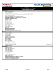
Series 31ί-B5 CNC for Turning STANDARD FEATURES Axis Control Digital Servo Function 1 Controlled Path 2 (up to maximum of 5) Simultaneously Controllable Axes (J801) (J803) Serial Encoder Interface Axis Names Selected from X,Y,Z,A,B,C Least Input Increment of 0.001mm, 0.0001", 0.001deg Inch/Metric Conversion (J876) Interlock per Axis Machine Lock Emergency Stop Overtravel Signal Stored Stroke Check 1 Mirror Image Follow-up Function Servo Off Mechanical Handle Feed Backlash Compensation Stored Pitch Error Compensation (J841) Operation Memory Operation DNC Operation MDI Operation Program Number Search Sequence Number Search Buffer Register Dry Run Mode Single Block Mode Manual Feed Mode (Jog) Manual Reference Point Return Manual Handle Feed (J835) Incremental Feed Interpolation Positioning (G00) Linear Interpolation Circular Interpolation Dwell (G04) Threading Skip Function (G31) Torque-limit Skip Automatic Reference Point Return (G28, G29) Reference Point Return Check (G27) 2nd Reference Point Return (G30) 31i-B5T 3/19/2012 (requires MPG) Page 1 Series 31ί-B5 CNC for Turning Feed Function Rapid Traverse Feedrate 240m/min (100m/min @0.0001mm increment) Rapid Traverse Feedrate Override (preset value, 25%, 50%, 100% settings) Feed per Minute Feed per Revolution Tangential Speed Control Cutting Feedrate Clamp Automatic Acceleration/Deceleration (Rapid Traverse: Linear; Cutting Feed: Linear or Exponential) Rapid Traverse Bell-Shaped Acceleration/Deceleration Feedrate Override 0-254% Jog Override 0-655.34 % Override Cancel Manual Synchronous Feed Programming EIA/ISO Automatic Identification Label Skip Parity Check Control In/Out Optional Block Skip Maximum Programmable Value - 8 digits Program Number - O with 4 digits Sequence Number - N with 5 digits Absolute or Incremental Command Programmable Data Input (G10) Decimal Point Input Setting in Diameter or Radius Plane Selection (G17, G18, G19) Rotary Axis Setting Rotary Axis Rollover Coordinate System Setting (G50) Automatic Coordinate System Setting Coordinate System Shift Direct Coordinate System Shift Setting Manual Absolute On/Off G Code System A Subprogram Calling Canned Cycles Multiple Repetitive Canned Cycles (G70-G76) (J877) Specifying the Radius of an Arc Auxiliary and Spindle Functions Miscellaneous Function - M with 8 digits Miscellaneous Function Lock High Speed M/S/T Interface Multiple Commands of Miscellaneous Functions (up to 3) Spindle Function - S with 5 digits Serial Spindle Interface (J850) Constant Surface Speed Control (J855) Spindle Override 0-254% 31i-B5T 3/19/2012 Page 2 Series 31ί-B5 CNC for Turning Tool Functions and Tool Compensation Tool Function - T7+1/T6+2 32 Tool Offsets Tool Position Offset Tool Nose Radius Compensation (J930) Tool Compensation Counter Input Tool Compensation Measurement Value Input A Part Program Storage & Editing 256KB Part Program Storage (J945) 63 Stored Part Programs Part Program Editing Part Program Protection Multi Part Program Editing (J956) Extended Part Program Editing Display Status Display Clock Function Current Position Display Program Display Parameter Setting Display Self Diagnosis Alarm Display Alarm History Display Help Function Run Time/Part Count Display (J971) Actual Cutting Speed Display Actual Spindle Speed/T Code Display Servo Adjustment Screen System Configuration Display English Language Data Protection Key Data Input/Output and Communications I/O Link or I/O Link i Interface A02B-0236-C192 in LCD Mount, A02B-0120-C192 in Stand Alone. Punch Panel with 2m Cable Reader/Punch Interface 1 (RS-232) (J900) External Workpiece Number Search External Data Input (J913) includes External Tool Offset External Message External Machine Origin Shift External Program Number Search Status Output Signal Other CD-ROM containing Product Manuals included in the BOM of the Root CNC Operation and Maintenance Handbook B-64487EN FS30ί/31ί/32ί-Model B Oper and Maint Handbook HONDA CONNECTOR Miscellaneous Conn: Qty 2 A02B-0120-K301 Qty 1 each A02B-0120-K323 & A02B-0120-K324 A02B-0236-K100 LCD or A02B-0265-K100 Stand Alone Spare Fuses A02B-0303-K001 8 CABLE CLAMPS Cable Clamps Grounding Bar 44B295864-001 GROUNDING BAR 11 SLOT 31i-B5T 3/19/2012 Page 3 Series 31ί-B5 CNC for Turning SERIES 31ί-B5 PACKAGE CHOICES Package A 2 Axes 2 Slot Rack LCD Mount Embedded Ethernet 15" LCD Color Touch PMC 24K Steps Serial Spindle CPU Card B2 Basic Function G421 Separate Type MDI (Vertical) Package B 2 Axes 2 Slot Stand Alone HSSB Embedded Ethernet PMC 24K Steps Serial Spindle CPU Card B2 Basic Function G421 G421 => Supports 2 Paths,12 axes (12 per path), 4 spindles (4 per path) => A02B-0323-C128 or equivalent PACKAGE DEPENDENT OPTIONS Automatic Data Back-up, 3 Sets of Back-up Data, SRAM + PPS PROFIBUS DP Master PROFIBUS DP Slave PROFIBUS DP Master PROFIBUS DP Slave HSSB Fast Ethernet Data Server 2nd Fast Ethernet Brd Fast Ethernet Data Server Remove HSSB 10.4" LCD A Color Tch 15.0" LCD Col w/ Tch CNC HSSB Card Sep MDI 2nd Fast Ethernet Brd 3rd Fast Ethernet Brd USB Memory I/O is available on LCD Mount CNCs & the LCD for S.A. 31i-B5T 3/19/2012 Page 4 Series 31ί-B5 CNC for Turning OPTIONS Series 31ί-B5 CNC Express Package A for Turning - 15" LCD Mount w/ Touch Screen. Series 31ί-B5 CNC Express Package B for Turning - 4 Slot Stand Alone. Choose Only 1. Package A Options PROFIBUS DP Master Board (J311, S731, J562#6552) Choose no more than two PROFIBUS DP Slave Board (J313, S732, J563#655C) Option Boards PROFIBUS Application Software, J535#655B, required for all PROFIBUS HSSB Board (High Speed Serial Bus) (J202) (includes Extended D/L Function,10m F/O cbl) 1st Fast Ethernet Board (J147) (Requires Ethernet or Data Server) Fast Ethernet Function (S707) (Uses FOCAS Protocol) Data Server Funct (S737,R953)(req's ATA Flash Mem Card)(Uses FTP for data transfer) 2nd Fast Ethernet Board (J147) (Additional Ethernet Port) Requires (S707). Manual Guide ί in Package A - Requires Custom Macro (J873) for full functionality. Manual Guide ί (S790) Manual Guide ί Multi Path Lathe (S786) for 2 or 3 paths. Requires (S790). Package B Options PROFIBUS DP Master Board (J311, S731, J562#6552) Choose no more than four PROFIBUS DP Slave Board (J313, S732, J563#655C) Option Boards PROFIBUS Application Software, J535#655B, required for all PROFIBUS 1st Fast Ethernet Board (J147) (Requires Ethernet or Data Server) Fast Ethernet Function (S707) (Uses FOCAS Protocol) Data Server Funct (S737,R953)(req's ATA Flash Mem Card)(Uses FTP for data transfer) 2nd Fast Ethernet Board (J147) (Additional Ethernet Port) Req's 1st Ethernet Board & (S707) 3rd Fast Ethernet Board (J147) (Additional Ethernet Port) Requires 2nd Fast Ethernet Board Use HSSB from Package B for the LCD. (Removes A02B-0207-J900) Required to order LCD. 10.4" LCD A Color w/ Tch Scrn (C084)(290x220mm), J682, Pen & Only one LCD 10m F/O cbl, A02B-0120-K323, A02B-0120-K324, A02B-0319-K191 15.0" LCD Color w/ Tch Scrn (C092)(400x320mm), J682, Pen & 10m Req MDI below. F/O cbl, A02B-0120-K323, A02B-0120-K324 CNC Side HSSB Board (incl's A02B-0207-J900,10m F/O cbl) Requires one Option Slot Without Standard CNC Display Unit - HSSB (J389) connects to Panel i or PC side HSSB. Without Standard CNC Display Unit - Embedded Ethernet (J390) connects to iPendant only Ethernet Display Function (R950 & J573#658N) Embedded Ethernet to PC, not for iPendant Sep Type MDI (Vert PC Type) (QWERTY) (290x160mm) A02B-0323-C128 or equivalent Sep Type MDI (ONG Type) (Vertical) (290x220mm) A02B-0323-C126#T or equivalent Sep Type MDI (ONG Type) (Horizontal) (230x220mm) A02B-0323-C125#T or equivalent Manual Guide ί in Package B - Requires Custom Macro (J873) for full functionality. Manual Guide ί (S790) RRequires (S790). Manual Guide ί Multi Path Lathe (S786) for 2 or 3 paths. 10.4" Color LCD A w/ Touch Screen does not support "Large Window Animation" in Manual Guide ί. High Speed Serial Bus (HSSB) includes: 31i-B5T Extended D/L Function J900 & 10m F/O Cable 3/19/2012 Page 5 Series 31ί-B5 CNC for Turning SERIES 31ί-B5 TURNING OPTIONS The following options may be ordered for Packages A or B Basic Function 0 G431 Basic S/W for up to 4 paths, 20 controlled axes, 12 per path, and 6 spindles, 4 per path Number of Paths Two Control Paths Minimum of 4 Axes Three Control Paths, requires G431 Basic Function Minimum of 6 Axes Four Control Paths, requires G431 Basic Function Minimum of 8 Axes Axis Control: up to 20 axes and 6 spindles are possible. 3rd Axis 4th Axis 5th Axis 6th Axis 7th Axis 8th Axis 9th Axis 10th Axis 11th Axis 12th Axis 13th Axis, Requires G431 Basic SW, changes to A13 Servo Card, 1 FSSB Servo Line 14th Axis 15th Axis 16th Axis 17th Axis 18th Axis 19th Axis changes to A24 Servo Card, 2 FSSB Servo Lines 20th Axis Number of Serial Spindles (default is one). >1 Spindle per path requires Multi Spindle Control. 2 Spindles 3 Spindles 4 Spindles 5 Spindles, Requires >= 2 Paths. 6 Spindles Multi Spindle Control. Required if more that one spindle is used per path. Analog Spindle. Analog Spindle (J860) replaces Serial Spindle (J850). Having Serial Spindle requires R584. Serial/Analog Spindle Control - includes Multi Spindle Control. 1 Serial Spindle and 1 Analog Spindle (R584, J850, J860) 2 Serial Spindles and 1 Analog Spindle 3 Serial Spindles and 1 Analog Spindle 4 Serial Spindles and 1 Analog Spindle, Requires >= 2 Paths. 5 Serial Spindles and 1 Analog Spindle 31i-B5T 3/19/2012 Page 6 Series 31ί-B5 CNC for Turning Axis Control Options Axis Control by PMC (up to 16 axes) (J804) Synchronous Axis Control (up to 6 pairs axes) (J843) Controlled Axis Detach (J807) Least Input Increment of 0.0001mm, 0.00001", 0.0001deg (J805) Dual Position Feedback (J704) Stored Stroke Check 2/3 (J840) Stored Limit Check Before Move (J749) Interpolation type pitch error compensation (S644) Bi-directional pitch error compensation (S656) Straightness Compensation (J747) (4 points) Interpolation Type Straightness Compensation (S639) (128 points) Position Switch (J846) Rotary Axis Control (J743) Operation Program Restart (J838) Tool Retract & Recover (J823) Manual Handle Retrace (J998) Manual Handle Feed 2/3 Units (J836) Manual Handle Interruption (J837) Change Active Offset Value with Manual Move (S825) Interpolation Polar Coordinate Interpolation (J815) Cylindrical Interpolation (J816) (requires 3rd Axis) Helical Interpolation (J819) (requires 3rd Axis) Thread Cutting Retract (J825) Variable Lead Threading (G34) (J827) Polygon Turning (J817) High Speed Skip (J848) Multi Step Skip (J849) 3rd, 4th Reference Point Return (J830) Reference Point Setting with Mechanical Stopper (J729) Linear Scale I/F w/ absolute address reference mark (J670). Requires Separate Detector I/F. Feed Function Bell Shaped Acc/Dec After Interpolation for Cutting Feed (J829) 2nd Feedrate Override (J810) Grinding Options Canned Cycles for Grinding (J640) (selectable per path with multiple repetitive cycles) 31i-B5T 3/19/2012 Page 7 Series 31ί-B5 CNC for Turning Programming Workpiece Coordinate System (G52-G59) (J894) Workpiece Coordinate System Preset (J917) Direct Drawing Dimension Programming (J870) Only one of these options Chamfering/Corner Rounding (J875) can be active per path. Special G Code B/C (J871) Custom Macro (J873) Additional Custom Macro Common Variables (J887) Interruption for Custom Macro (J874) Pattern Data Input (J884) Multiple Repetitive Canned Cycles II (J889) Canned Cycles for Drilling (J890) Mirror Image for Dual Turrets (G68, G69) (J881) Coordinate System Rotation (J893) Series 15 Tape Format (J882) Macro Executor (J888) 96K Reserved for System S/W. Choose only one Macro Macro Executor + C-language Executor (J734) 700K Reserved for System S/W. FANUC PICTURE Executor (R644) 2M Reserved for System S/W. Available with J888/J734. Custom Software Size 512KB (J738#512K) Not with J734 or R644. Custom Software Size 2MB (J738#2M) Not with R644. Custom Software Size 4MB (J738#4M) Choose only one Custom Software Size. Custom Software Size 6MB (J738#6M) Custom Software Size 8MB (J738#8M) Custom Software Size 12MB (J738#12M) PMC Options PMC with 32K Steps (H990#32K) PMC with 64K Steps (H990#64K) PMC with 100K Steps (H990#100K) Choose Only One. PMC with 300K Steps (H990#300K) Multi-path PMC function (3 paths) (R855#3) Multi-path PMC function (5 paths) (R855#5) Choose Only One. PMC symbol, comment, and message capacity expansion (512KB) (R856#512K) PMC symbol, comment, and message capacity expansion (1MB) (R856#1M) PMC symbol, comment, and message capacity expansion (2MB) (R856#2M) Only One. Function Block Function (R852) I/O Link expansion 2nd Channel w/ A20B-1007-0680 and 1m cable. I/O Link expansion 3rd Channel w/ A20B-1008-0360 and 1m cable. Dual Check Safety (S661) Req's I/O Link i,I/O Link 3rd Channel or PROFIBUS Master. 0 I/O Link ί will be used for Dual Chack Safety. Check here: Auxiliary and Spindle Functions 1st Spindle Orientation (J853) (Applies to 1st Spindle per Path) (req's Serial Spindle) Actual Spindle Speed Output (J856) (requires Spindle Encoder) 2nd Miscellaneous Function (B8-digit binary) (J920) Rigid Tapping (J828) (requires Canned Cycles, Analog Spindle requires Spindle Encoder.) See Drives Tab for Spindle Separately Mounted Position Encoder. 31i-B5T 3/19/2012 Page 8 Series 31ί-B5 CNC for Turning Tool Functions and Tool Compensation Assignable by parameter per path. 64 Tool Offset Pairs (J925) 99 Tool Offset Pairs (J926) Choose only one 200 Tool Offset Pairs (J927) Y-axis Offset (J934) (3rd or 4th axis required) Tool Geometry and Wear Compensation (J931) Tool Life Management (J935) Automatic Tool Compensation (S618) Direct Input of Measured Offset (J933) Part Program Storage & Editing Total PPS in the system, available to all paths. 512KB Part Program Storage (J946) (Approx 1280m) 1MB Part Program Storage (J947) (Approx 2560m) Choose only one 2MB Part Program Storage + 1000 Stored Part Programs (J948) (J953) (Approx 5120m) 4MB Part Program Storage + 1000 Stored Part Programs (J949) (J953) (Approx 10240m) 8MB Part Program Storage + 1000 Stored Part Programs (J959) (J953) (Approx 20480m) Playback (J879) FANUC Picture FANUC Picture Function (S879) Req's LCD w/ Tch Pnl, deletes J682, not w/ J734/J888/R644 FANUC Picture Function for non-Touch panel display (S944) Not w/ J734, J888 or R644 Ethernet or HSSB Options Use Embedded Ethernet for BOP2 or Ladder Edit Function Basic Operation Package (BOP2) Function (J814) & CD (Also works w/ embedded Ethernet) CNC Screen Display Function (J858) Application Disk for HSSB Application Disk for Ethernet CNC Screen Dual Display Function (S884) CNC Screen Display for 19" Panel ί (R624) 19" Panel ί requires one Enlarged CNC Screen Display for 19" Panel ί (R673) of these options Ladder Edit Function (J820) (Also works w/ embedded Ethernet) Ethernet/IP Adapter Function (R967), requires Ethernet (S707) Ethernet/IP Scanner Function (R966), requires Ethernet (S707) Display Graphic Display (J972) Requires LCD or CNC Screen Display Function Software Operator Panel (J960) Software Operator Panel General Purpose Switch (J961) Selection of Five Optional Language (R521) Touch Panel Control (J682) Req'd when iPendant w/ Touch Screen is the only display. Data Input/Output and Communications Compact Flash Card 128MB, Card Adapter B Compact Flash Card 1GB (suggested for use with Data Server) , 2 Card Adapters 2nd Reader/Punch Interface (RS-232) (J901) i AdaptS Check to override required DVD. i AdaptS (S898) maintains a constant load during part processing by modifying the feedrate override. This allows for the fastest possible cycle time based on the condition of the tool, part geometry and material variation. By maintaining the manufacturer’s recommended load on the tool, tool life can also be extended. i AdaptS works on the first serial spindle in the first path only. Req's J856,J873,J810,J738#2M,J734. i AdaptS S/W DVD D75F-0102-PB00 i AdaptS S/W DVD with FANUC Picture (R644). Req's R644 >=J738#6M. D75F-0103-PB00. 31i-B5T 3/19/2012 Page 9 Series 31ί-B5 CNC for Turning Cables Optional: Replace 10m cable for LCD orderable with Package B with one of the following: Fiber Optic Cable, CNC to LCD, 1m Fiber Optic Cable, CNC to LCD, 5m Fiber Optic Cable, CNC to LCD, 20m Different MDI's Separate Type MDI (ONG) (Vertical) Replaces Vertical QWERTY in Pkg A A02B-0323-C126#T or equivalent Separate Type MDI (ONG) (Horizontal) Replaces Vertical QWERTY in Pkg A A02B-0323-C125#T or equivalent Product Manuals Series 30ί/31ί/32ί-B Descriptions Series 30i/31ί/32ί-Model B Connection Manual Hardware Series 30ί/31ί/32ί-Model B Connection Manual (Function) Series 30i/31ί/32ί-Model B Maintenance Manual * Series 30ί/31ί/32ί-Model B Parameter Manual * Series 30ί/31ί/32ί-B User's Manual Common & Lathe * Series 30ί/31ί/32ί FAST Ethernet/Data Server Operator's Manual Manual Guide ί Operator's Manuals & Setup Guide Series 30ί/31ί/32ί Model B Operation and Maintenance Handbook 31i-B5T 3/19/2012 Page 10


