1
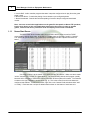
Nexus FEC Operator's
Manual & Technical Guide
© 2010 Zone Systems, Inc.
Nexus FEC Operator's Manual & Technical Guide
© 2010 Zone Systems, Inc.
All rights reserved. No parts of this work may be reproduced in any form or by any means - graphic, electronic, or
mechanical, including photocopying, recording, taping, or information storage and retrieval systems - without the
written permission of the publisher.
Products that are referred to in this document may be either trademarks and/or registered trademarks of the
respective owners. The publisher and the author make no claim to these trademarks.
While every precaution has been taken in the preparation of this document, the publisher and the author assume no
responsibility for errors or omissions, or for damages resulting from the use of information contained in this
document or from the use of programs and source code that may accompany it. In no event shall the publisher and
the author be liable for any loss of profit or any other commercial damage caused or alleged to have been caused
directly or indirectly by this document.
Printed: April 2010 in Dover, DE; USA
Publisher
Zone Systems, Inc.
Managing Editor
Daniel Shurina
Technical Editors
Simon Willetts
John MacBlain
Bhupesh Patel
Contents
3
Table of Contents
Foreword
Part I Nexus FEC User's Manual
1 Nexus ...................................................................................................................................
FEC Software
0
5
5
Nexus Start Server
.......................................................................................................................................................... 6
Uploading Pack
.........................................................................................................................................................
Settings
7
Uploading Pack
.........................................................................................................................................................
Sounds
7
Managing Packs
.........................................................................................................................................................
& Adjusting Pack Volume
8
Application License
..........................................................................................................................................................
Server (ALS)
9
Licensing Nexus
.........................................................................................................................................................
FEC
9
Nexus Control ..........................................................................................................................................................
Centre
9
Managing Game
.........................................................................................................................................................
Formats
10
Setting Pack
.........................................................................................................................................................
Names
12
Acacia Audio .......................................................................................................................................................... 13
Zone IO Server
..........................................................................................................................................................
(ZIOS)
14
Nexus Print Server
.......................................................................................................................................................... 14
Nexus Scoreboard
.......................................................................................................................................................... 14
2 Nexus...................................................................................................................................
FEC Control Hardware
15
Nexus License
..........................................................................................................................................................
Dongle
15
Nexus Radio Base
..........................................................................................................................................................
Unit
16
3 Nexus...................................................................................................................................
FEC Player Hardware
17
Nexus FEC Vest
.......................................................................................................................................................... 18
Nexus FEC Phaser
.......................................................................................................................................................... 18
Nexus FEC Outpost
.......................................................................................................................................................... 19
Part II Introduction to Equipment Maintenance
22
1 Assigning
...................................................................................................................................
the Right People
22
2 Maintaining
...................................................................................................................................
a Productive Work Area
23
3 Maintaining
...................................................................................................................................
Inventory and Scheduling
23
Part III Maximizing Equipment Up-Time
26
1 Weekly
...................................................................................................................................
Testing
26
2 Reactive
...................................................................................................................................
Maintenance & Troubleshooting
27
No Charge
.......................................................................................................................................................... 27
No Sound
.......................................................................................................................................................... 28
No IR Receive .......................................................................................................................................................... 28
No LED
.......................................................................................................................................................... 29
No Trigger .......................................................................................................................................................... 29
No Laser
.......................................................................................................................................................... 29
No IR Transmit
.......................................................................................................................................................... 30
Index
0
© 2010 Zone Systems, Inc.
3
Part
I
Nexus FEC User's Manual
1
5
Nexus FEC User's Manual
Congratulations on your ownership of the Nexus FEC product line by P&C Micros™. This
equipment is designed to be the industry standard for immersive game play and laser tag technology.
The FEC line of Nexus products boast aesthetically-pleasing light-weight packs, easy to use graphical
interfaces, illuminated vesting racks, and optional bases and reloads that create an experience that your
guests will never forget.
For all inquiries pertaining to your equipment, please refer to the following contact
information:
If you are located in North America or South America, your system is supported by Zone Systems, Inc.,
based out of Dover, DE.
Zone Systems, Inc.
1055 Barl Court
Dover, DE 19901; USA
Tel. (302) 730-8888
Fax. (302) 336-9698
Web. www.zonelasertag.com
If you are located in Europe, your system is supported by Zone EU Ltd., based out of Leicester, UK.
Zone EU Ltd.
171 Belgrave Gate, Leicester, LE1 3HS, UK
Tel. +44 116 2425225
Fax. +44 116 2425925
Web. www.zoneeu.co.uk
If you are located in Australia, your system is supported by P&C Micros, based out of Melbourne.
P&C Micros Pty Ltd
5 Harker St, Burwood, 3125, Australia
Tel. +61 (03) 98889333
Fax. +61 (03) 98889001
1.1
Nexus FEC Software
The following applications are running on the game PC in order to control the Nexus FEC laser game:
1. Nexus Start Server - The communication engine between the game PC, the packs, and arena devices
like outposts & reloads
2. Application License Server (ALS) - The licensing interface between the game server and the Nexus
License Dongle
3. Nexus Control Centre - The graphical user interface used to perform routine operations like starting /
stopping games and switching between game formats
4. Zone I/O Server (ZIOS) - The communication engine between the game server and remote clients like
the Scoreboard, Print Server, and Acacia Audio applications
© 2010 Zone Systems, Inc.
6
Zone Managers' Guide to Equipment Maintenance
5. Acacia RAP - Audio controller program that starts / stops the configured music play list as the game
starts / stops
6. Nexus Print Server - Controls the printing of score sheets on pre-configured printers
7. Nexus Scoreboard - Controls the real-time updating of scores to the pre-configured scoreboard
monitor
Note - there are several other applications on the game PC that pertain to Nexus FEC products,
but the ones above are the only applications that need to be running in order to operate
games, control arena music, print score cards and display scores on the scoreboard.
1.1.1
Nexus Start Server
The Nexus Start Server handles radio communication with the packs, as well as TCP/IP
communication with the base units. In the field to the right, there are two tabs; "packs" & "network".
The "packs" tab (shown below, Fig. 5) shows the installed packs and the "network" tab shows the
bases.
Fig. 5
One thing to notice is at the bottom right, where it reads "ALS Status". Make sure that it reads
"online," because if it is "offline," the game server is not communicating with the ALS program (usually
because ALS is not open) to retrieve the license information and the system will not work. The other tab
to select on the right "network" is shown below (Fig. 6). This is the screen from which the bases are
configured and enabled. To add or edit a base, right click on the "network" field and select either "add"
or "modify." Each base has a unique IP address that is written on the bottom of each base unit.
© 2010 Zone Systems, Inc.
Nexus FEC User's Manual
7
Fig. 6
1.1.1.1
Uploading Pack Settings
With Nexus FEC products, pack settings can be uploaded to packs through the radio.
Uploading the pack settings restores the programmed memory to the pack, and is often used to correct
malfunctions like incorrect LED patterns. To upload settings, right-click on a pack in the "packs" field,
choose "select" to put a star next to the selected packs (you can select as many packs as necessary);
then select the "upload" tab to the left and click the "upload" button. The small information screen below
(Fig. 7) will appear, then click ok to begin settings upload.
Fig. 7
1.1.1.2
Uploading Pack Sounds
With Nexus FEC equipment, the sounds can be uploaded to pack(s) through the radio. This
feature is used to reprogram packs if they are missing some or all of their sounds. To perform this, rightclick on a pack in the "packs" field to the right, choose "select" to place a star next to the pack ID (you
can select multiple packs if necessary). Then, select the "upload" tab to the right and click the
"sounds" button. A small confirmation window will appear, to which you answer "yes" to begin uploading
© 2010 Zone Systems, Inc.
8
Zone Managers' Guide to Equipment Maintenance
sounds. You will then notice a number appear in the Tx Buf column of the "packs" field next to the first
ID that was selected for program. This number will count down and reach "zero" when the upload is
complete.
Fig. 8
1.1.1.3
Managing Packs & Adjusting Pack Volume
To add / remove packs from the list of packs in the "packs" field, click on the "pack" tab to the
left and select "add pack" or "remove pack" to add / remove packs from the list. You can also adjust
pack volumes by right-clicking on a pack ID in the "packs" field, then choose "select" to place a star
next to the desired pack ID (you can select multiple packs if necessary), and click on the "set volume"
button to the left to adjust the pack volume of selected packs. The packs can also be blocked /
unblocked by right-clicking on a desired pack ID and choosing either "block" or "unblock". Note - a
blocked pack does not communicate with the game server, but an unblocked, offline pack
slows down the database, so every pack should ideally be either online or blocked.
Fig. 9
© 2010 Zone Systems, Inc.
Nexus FEC User's Manual
1.1.2
9
Application License Server (ALS)
The Application License Server (ALS) controls your license information and communicates
constantly with the Nexus License Dongle (connected to your PC by USB) and the Nexus Start Server.
The ALS program needs to run constantly in the background in order to run games. Upon opening the
ALS from the path My Computer -> C Drive -> Program Files -> P&C Micros -> Application License
Server, you should see a screen similar to the one below.
Fig. 11
Notice the "Site License Details" at the top of the display that shows information about your
particular site, and the "Days Remaining" at the top left. If you do not see this information when the ALS
is loaded, the license dongle is not properly connected. Try re-seating the license dongle into the USB
port and click Tools -> Dongle Port Scan from the ALS window. The scanner should find the dongle and
the information should appear.
1.1.2.1
Licensing Nexus FEC
The Nexus FEC system is licensed through the ALS program. To enter the new license, click
"Licenses", then "Update Site License Days". In the field that appears, type in the new alphabetic
license key and press "ok". The "Days Remaining" field will change displaying the amount of days
remaining on the new license.
1.1.3
Nexus Control Centre
The Nexus FEC Control Centre is the main user interface for routine laser game functions like to
switch between game formats, adjust game formats, change pack names, and of course to start / stop
games. Once the Control Centre is opened, the basic display appears, shown below (Fig. 12).
Fig. 12
© 2010 Zone Systems, Inc.
10
Zone Managers' Guide to Equipment Maintenance
The first thing to notice when the Control Centre is opened is the status at the left. Make sure
the status says "online" as above. If the status is "offline", either the Nexus Start Server or the ALS
program are not running. The most basic functions of the Control Centre are to start game, finish game,
or abort game:
Start Game: Begins the selected game format which will run for the preset time, and automatically finish
Finish Game: Ends the selected game early and tallies scores
Abort Game: Ends the selected game early, and deletes all scores from the aborted game
1.1.3.1
Managing Game Formats
Selecting a Game Format
To switch between game formats, click on the "Game Settings" button to expand the installed
game formats. From this window (below, Fig. 13), you can observe the preset configurations for the
selected game format in the field to the right, you can set the game time, and double-click on a game
format to select it for the next game.
Fig. 13
Adjusting Game Parameters
In order to change game parameters, click on the "Management" button at the top, enter the
pass code and press "E". Note - The default pass code is "1234" unless it has been changed. To edit
game parameters, highlight the desired game format and click the "settings" button. The below screen
will open (below, Fig. 14). Make desired changes and click "Done" to save changes.
© 2010 Zone Systems, Inc.
Nexus FEC User's Manual
11
Fig. 14
Adjusting Game Scoring
To adjust game scoring, access the above display from the "Management" button of the Control
Centre; and click the "Scoring" button to open the below display (Fig. 15). Simply select the desired
game format, then select the desired scoring event to edit from the below field, and set the score for the
applicable event at the bottom-right. Click the "Done" button when finished to save changes.
Fig. 15
© 2010 Zone Systems, Inc.
12
Zone Managers' Guide to Equipment Maintenance
Adding, Removing, & Renaming Game Formats
With Nexus FEC, it is possible to set up pre-configured games and rename them for quick
access later. To perform these functions, open the Control Centre, and click the "Management" button
to open the below display (Fig. 16). To add new games to your list, click "New" to remove undesired
games from your list, click "Remove", and to rename pre-configured games, click "Rename."
Fig. 16
1.1.3.2
Setting Pack Names
With Nexus FEC, you may set the pack names to any alias, up to 8 characters long. To
perform this operation, make sure the pack whose alias you wish to change appears "online" in the
Nexus Start Server. Next, open the Control Centre, click the "Packs" button and enter the pass code to
the right (default is "1234"). Enter the desired pack name (shown below, Fig. 17) and click "Save to all
online packs" to update the alias to the pack through the radio.
© 2010 Zone Systems, Inc.
Nexus FEC User's Manual
13
Fig. 17
1.1.4
Acacia Audio
Acacia Audio applications allow the option to configure a single playlist to play through the
game PC and start / stop when the game starts / ends. To configure a playlist, open the Acacia playlist
editor from start -> programs -> P&C micros -> Acacia Audio. A screen similar to the one below will
appear (Fig. 7):
Fig. 7
To load music files in to the editor, a single playlist must first be created. To create a single
playlist, click the "add" button at the left, name the playlist "default." The playlist must be named
"default" in lower-case letters. Once the playlist has been created, a list of available sound files will
populate in the field to the right. The files that already appear in this field are all arena sounds. Do not
© 2010 Zone Systems, Inc.
14
Zone Managers' Guide to Equipment Maintenance
add these arena sounds to the playlist. Instead, click "add" at the right to add .mp3 files into the
"available files" list. They will appear at the end of the list once they are added. Once all desired sound
files are made available, click "modify" in the middle to modify the single playlist. Now you can doubleclick on the song titles in the "available files" field to add them to the "default" playlist. Once your
"default" playlist is complete, exit out of the playlist editor, double-click on the Acacia Audio
Synchronizer at start -> programs -> P&C micros -> Acacia Audio to synchronize playlist. Finally, open
the Acacia RAP application in the same folder and leave RAP open and minimized to enable game
control of the playlist.
1.1.5
Zone IO Server (ZIOS)
The ZIOS application only needs to run in the background and can be opened from the path: My
Computer -> C Drive -> Program Files -> P&C Micros -> Zone IO Server. The ZIOS program allows the
Nexus Start Server to communicate with other applications, like the print server and scoreboard.
1.1.6
Nexus Print Server
The Nexus Print Server communicates scoring and game information to the printer for printing
score sheets. Normally, the print server is minimized and running in the background, but if you expand
the print server, a display will appear similar to the one below (Fig. 18). The field to the left lists the
most recent games played, so you can open a previously played game and select to either print score
sheets for some or all players using the fields to the right. The "Designer" button at the bottom-right
is used to adjust the print fields of the score sheets and should only be used with a Zone
Systems technician.
Fig. 18
As long as the print server is running, it will automatically print the score sheets from any game
once it is finished (provided the auto print feature is "on" at the bottom-right of the print server screen).
1.1.7
Nexus Scoreboard
The Nexus Scoreboard displays real-time updates on scoring information while a game is in
progress, and it displays score totals once a game is finished. The score totals from the previous game
will remain on the scoreboard until the next game is started. The scoreboard display is constantly
changing, but the basic background image is similar to below (Fig. 19).
© 2010 Zone Systems, Inc.
Nexus FEC User's Manual
15
Fig. 19
In order for the scoreboard to function properly, it must be configured to display on a
second monitor and the second monitor must accept either 1280x720 VGA or 1920x1080 VGA
resolution. To configure the second monitor, right-click on the desktop and click "properties" and
access the "settings" tab. Once in the Windows display settings, select to allow the "desktop to extend
to second monitor" and set the resolution of the second monitor to either 1280 x 720 or 1290 x 1080
(which ever is supported). Any time changes are made to the display settings or configurations, the
scoreboard must be closed down and re-opened.
1.2
Nexus FEC Control Hardware
Control hardware is comprised of a PC, monitor, Nexus dongle, and radio base unit, and a
network hub. The dongle is to remain plugged into a USB port on the game PC and the radio base unit
is to remain connected to a COM port (COM1 or COMA by default). The network hub is used to connect
to the arena bases as well as an internal network. With Nexus FEC, since the game PC uses TCP/IP
to communicate with the bases, the bases are assigned unique IPs and are treated as any other
network device like a printer or a fax machine would be treated on a standard LAN.
1.2.1
Nexus License Dongle
The Nexus License Dongle
The license dongle is a button reader that contains unique license information about your site.
The dongle is communicated with via the ALS (Application License Server). The dongle has to remain
plugged into the same USB port all the time in order for the games to run properly.
© 2010 Zone Systems, Inc.
16
Zone Managers' Guide to Equipment Maintenance
Fig. 20
1.2.2
Nexus Radio Base Unit
The Nexus Radio Base Unit may look similar to the picture below (Fig. 20) or it may be mounted
in a different type of box, but the basic functions are the same. The radio needs 12VDC power to work,
and it needs to be connected to the game PC via a serial connection to COM A (by default) to the game
PC. The indicators include the power LED, which shows that the unit is powered on; the Rx LED, which
shows that the unit is receiving information from the packs; and the Tx LED, which shows that the unit is
transmitting information to the packs.
© 2010 Zone Systems, Inc.
Nexus FEC User's Manual
17
Fig. 21
1.3
Nexus FEC Player Hardware
Nexus FEC Player Hardware consists of arena devices such as outposts, mines or reloads
(mines & reloads are not covered in this manual), as well as the vests & phasers.
Definitions
Let the "pack" be defined as the combination of the vest and the phaser (gun), while "vest" is
defined as the vest excluding the phaser and phaser cable. "PCB" stands for Printed Circuit Board.
Background
The NFEC vest is designed to be sleek and low-profile to minimize wear and tear on the
electrical components. While the laser is the visual sign of a pack firing, the infrared signal, or IR, that
emits from the gun is the actual means of deactivating the opposing pack.
Operation
There are 5 modes that each pack will cycle through during it's life:
1. IDLE - Indicated by a slowly flashing LED pattern; the vest is switched on, but not executing any
commands.
2. START - The LEDs will go dark as the countdown begins to start the game.
3. GAME MODE - Indicated by a rapid flashing LED pattern; The pack is now updating scoring
information to the game PC.
4. END - The "End Game" sound occurs as the pack returns to IDLE mode.
5. CHARGE - The shoulders flash a quick, yellow LED pattern when in charge mode (Note - the pack
must be switched "on" to properly charge the battery).
© 2010 Zone Systems, Inc.
18
1.3.1
Zone Managers' Guide to Equipment Maintenance
Nexus FEC Vest
The NFEC vest has 7 separate PCBs in it, excluding the pack radio unit, which include:
·
·
·
·
·
2 x shoulder PCBs
2 x chest PCBs
1 x back PCB
1 x charger PCB
1 x NFEC plugin
There are ribbon cables (vest cables) that connect the back to the shoulders (long), and similar
cables to connect the shoulders to the chest PCBs (short). By opening the back cover, you will see the
components shown below (Fig. 22).
Fig. 22
1.3.2
Nexus FEC Phaser
The NFEC phaser can be opened up by removing the 7 x 3mm hex screws and the left half-shell
can be removed by disconnecting the 6-pin connector that attaches it to the phaser PCB. The remaining
components will stay attached to the right half-shell for inspection (shown below, Fig. 23). When reattaching the two half-shells, the plastic trigger can be tricky. It has to be held in place while the two
shells are attached, and there are molds available for sale from Zone System that hold the plastic trigger
in place while the shells are re-connected.
© 2010 Zone Systems, Inc.
Nexus FEC User's Manual
19
Fig. 23
1.3.3
Nexus FEC Outpost
The NFEC "outpost" is also called the "base" (Fig. 9). The bases are connected individually to
the network hub that is connected to the game PC, and configured with unique IPs in the game server
(see section . The base will flash the LED color of the team to which it is assigned. Upon starting and
finishing a game, the bases will sound an alarm, and they will go through different modes of play as they
are tagged.
FIg. 11
Each base has 4 settings that are adjusted in the game parameters of the Nexus Control Centre
(see section 1.1.3.1). The available base settings are:
1. Off - You have chosen to turn off the Outposts/Bases.
2. Normal - You can only destroy it.
© 2010 Zone Systems, Inc.
20
Zone Managers' Guide to Equipment Maintenance
3. Defense - You can destroy it and it will give you a warning and then will tag you or anyone within the
vicinity of the Outpost/Base area
4. Aggressive - You can destroy it but it will not give you any warning and will destroy you or anyone
within the vicinity of the Outpost/Base area
© 2010 Zone Systems, Inc.
Part
II
22
2
Zone Managers' Guide to Equipment Maintenance
Introduction to Equipment Maintenance
It is encouraged that you spend some time familiarizing yourself with the system and your
equipment. With all manufactured items, there is a "bath-tub curve" for faults. This means that most
faults show themselves either in the first 5% or the last 5% of the product's lifespan. All our equipment
is built uniformly and tested thoroughly before it goes out the door, but there is no test as thorough as
real life. If there are any initial conflicts with your equipment, we all want to know about them before the
grand-opening if possible.
Each store is different and has different demands that must be met by the equipment and the
staff, so it is up to you to lay out the foundation of what will become your maintenance culture. This
includes assigning people to particular jobs, holding them accountable with periodic checklists, and
providing them with maintained inventory of spare parts so they can do their jobs well.
2.1
Assigning the Right People
Everyone should be involved in the maintenance culture, but an important decision is to assign
someone as the primary laser tag game technician. This should not be a 16 year-old person who is in
school until 4pm, but someone who is available during the daytime -- someone with whom our technical
support staff can develop a relationship to guide him/her through the more technically-intensive aspects
of his/her job. In many stores, the primary game technician is also a shift manager or it may be the
general manager.
Another important decision is to assign 1-2 shift employees as the equipment testers. There is
no rule that the tester(s) and technician(s) cannot be one in the same. Only the roles are divided.
Testers need only basic computer skills, but you should assign people who are going to be thorough
enough to pick up details like missing screws or buckles on the packs.
Finally, all staff members who are involved with running games should be versatile enough to
solve simple issues on-the-fly. For example, if you've got one pack with a bad gun and another pack
with a bad vest, everyone should think to combine the good gun with the good vest to make one working
pack out of two non-working packs.
To sum up, the following people are going to be involved:
1. Primary Game Technician
i. In charge of troubleshooting equipment glitches & making small repairs, & sending / receiving
repair orders to / from Zone Systems, Inc.
ii. Should be someone available during the day time
iii. Can expect to spend ~ 1-2 hours per week making repairs
2. Equipment Tester(s)
i. In charge of testing equipment, uploading settings / sounds to packs, & completing weekly
checklists to be handed over to management and the primary game technician
ii. Should be someone available when the store is closed for 1-2 hours per week to test
equipment
3. Game Shift Employees
i. In charge of labeling faulty equipment when it is brought to their attention, and may be
responsible for making quick 1-2 minute repairs.
ii. Should be enthusiastic about their job, well-trained on your company procedures for handling
maintenance, and versatile enough to think outside the box at times.
© 2010 Zone Systems, Inc.
Introduction to Equipment Maintenance
2.2
23
Maintaining a Productive Work Area
In order to properly maintain your equipment, a clean area is necessary in which tools and parts
are easily accessible. A clean, well-lit, flat-top bench should be made available that is large enough to
lay one vest flat from end-to-end. Adequate power outlets should be available as well as a maintained
tool kit. The recommended tool kit should include:
·
·
·
·
·
·
·
·
·
·
1 x 2.5mm hex screwdriver
1 x 3.0mm hex screwdriver
1 x pair needle-nose pliers
1 x pair side-cutters (snips)
1 x jewelers flat-head screwdriver
1 x jewelers philips-head screwdriver
1 x hot glue gun
1 x roll electrical tape
1 x multimeter -- with continuity, DC voltage, & DC current measurements
1 x soldering pen -- for soldering / desoldering wires only (not for use on circuit boards)
An additional option is to have an area near the work bench to hang 2-3 tagged vests and
available charging cables are an added benefit in order to test packs for charging or to keep packs
charged that are not being used.
2.3
Maintaining Inventory and Scheduling
Inventory:
To keep a well-maintained site, it is recommended that you keep a stocked inventory of
commonly-used consumable parts as well as a few replacement circuit boards for repairs. This will help
minimize your downtime and save shipping cost by handling common issues in-house rather than
sending easily-fixed problems to Zone Systems for repair. A list of replaceable parts to keep on hand
includes:
·
·
·
·
·
·
·
·
·
·
·
·
·
·
·
·
1 x box 4x25x3mm hex screws (phaser)
1 x box 4x20x3mm hex screws (phaser)
1 x box 4x16x3mm hex screws (phaser)
1 x box 4x12x2.5mm hex screws (vest)
4 x 1/2 phaser shells w/ components (2L, 2R)
3 x NG phaser cables
3 x NG vest cables (long)
3 x NG vest cables (short)
3 x NG phaser buckles (phaser)
3 x NG bungee straps (phaser)
4 x NG gundoms (gun)
1 x roll lead-free solder
5 x hot glue sticks
2 x NG batteries (spare)
2 x NG stand-alone battery chargers (to keep spare charged batteries)
2 x NG LCD displays
© 2010 Zone Systems, Inc.
24
Zone Managers' Guide to Equipment Maintenance
· 4 x NG speakers
· 2 x NG laser / IR modules w/ hand sensors
Please email [email protected] for pricing information.
It is not as common that faults occur with the circuit boards as with parts like cables and
plastics -- but in case it does happen, a list of recommended spare circuit boards to keep on site
includes:
·
·
·
·
·
·
1 x NG left shoulder board
1 x NG right shoulder board
1 x NG left chest board
1 x NG right chest board
1 x NG back board
1 x NG charger board
Scheduling:
The goal of effective scheduling is to be at 100% availability every Friday night. This means that
all your packs are functional by the start of your busiest days of the week. The key to successful
operation during your up-time lies with how successfully you handle your down-time. In other words,
take advantage of closed hours to maintain your equipment.
Scheduled maintenance is a two-fold attack. The first part consists of the equipment tester(s)
testing the equipment and completing the Zone Systems recommended checklist, available in the
appendix.
The second part of scheduled maintenance includes the primary game technician performing
repairs on any packs that have been taken out of service, then addressing issues brought to his/her
attention by the secondary game tech(s). This should be done during closed day-time hours.
© 2010 Zone Systems, Inc.
Part
III
26
3
Zone Managers' Guide to Equipment Maintenance
Maximizing Equipment Up-Time
Anyone who can use a screwdriver has an opportunity to save your store downtime. A couple
common faults that display themselves in games are that the gun stops working properly or the vest
completely dies. The game operators are busy, so they are not expected to perform actual repairs that
take longer than 2 mins -- however the faster and more accurate they can label a pack with a particular
issue saves the operator time he/she could be spending running games; and it saves the game tech
time isolating pack issues.
Preventative maintenance, for our purposes, consists only of testing and noting known faults.
This allows smaller problems to be addressed before they become big problems. Contradictory to
popular thought, spending a couple hours per week testing equipment actually decreases the amount of
time required for service. Over the years, we have seen many sites who do not address issues until they
put a pack completely out of service. The packs continue to pile up until the game tech has an
opportunity to work on them (usually once / week), but he/she is only addressing major issues and
seems to be unaware that while the packs that are out of service are going back in service, the following
week's issues have already begun manifesting in the packs that are, at this point, still operational.
Therefore, he/she never gets "ahead of the game."
3.1
Weekly Testing
Weekly Testing & Checklists
Please see Appendix for a basic testing checklist to be completed the following testing
procedure. Record the date, name(s) of tester(s), as well as any additional issues for the technician.
Testing Procedure
Have your tester(s) perform the following testing procedure once / week, preferably at the
beginning of the week, so the primary game technician has an opportunity to address the issues before
the following Friday:
1. Visually inspect each vest for missing or broken buckles and for missing screws. If a buckle is
broken or missing, note the pack ID on the checklist as "no gun buckle" or "no vest buckle" depending
on the location of the bad buckle. If a screw is missing, note the pack ID on the checklist as "no
screw."
2. Grab one vest and plug / unplug the charging socket. Make sure it goes in/out of charge mode
properly. If it does not, please determine if the appropriate voltage (~7.2 - 7.9 VDC; center-positive) is
received at the charging cable. If it is, mark the pack as "no charge." If proper voltage is not supplied by
the charging cable, mark the charging cable for the technician to address but do not use it in the
meantime.
3. Power cycle each vest (off & on) and listen for the boot-up sound. If no boot sound is audible, note
the pack as "no sound."
4. With all packs switched on, in "idle" mode -- start a solo game from the game server. Try shooting
each pack. If a pack's trigger does not engage properly, note the pack on the checklist as "no trigger."
If a pack shoots but does not fire laser, note the pack on the checklist as "no laser." Now try tagging
other vests with the pack being tested. If it does not tag other packs, note the pack on the checklist as
© 2010 Zone Systems, Inc.
Maximizing Equipment Up-Time
27
"no IR transmit."
5. Check to make sure that all packs make the firing sound during a game. If a pack does not make the
firing sound, upload sounds to the pack through the game server. If this does not work, note the pack on
the checklist as "no sound."
3.2
Reactive Maintenance & Troubleshooting
Regardless of the fault, troubleshooting pack hardware is always the same. Basically, take the
bad pack and compare to a good pack (100% working). Begin moving components from the bad pack
on to the good pack in a logical progression until the fault can be traced to a single component (that is,
the component which the fault follows). Once the bad component has been identified, either send that
component in to Zone Systems for repair (if it is a PCB) or replace with spare (see sect. 2.3 for
recommended spare parts inventory).
See section 1.3.1 - 1.3.2 for pics of back PCB and internal shots of the phaser shell.
3.2.1
No Charge
1. No Charge Identified by: (1) The pack may not go into charge mode when plugged in to a charging unit, or
(2) the pack may go into charge mode, but still behaves as though the battery is flat once removed from
charge.
Testing: Measure voltage at the charging cable. It should read ~ 7.2-7.9VDC center-positive at
the charging cable. However, (2) It is possible for the vest to go in charge mode, but no charge is
actually reaching the battery. To determine if charging is functional, use a modified charging cable with
an open + line to use with an ammeter (see Fig. 11, below). Note - a modified cable for current
measurement is available for sale from Zone Systems, Inc.
© 2010 Zone Systems, Inc.
28
Zone Managers' Guide to Equipment Maintenance
Fig. 20
Fixing: Whether the pack does not go into charge mode (1), or if the pack does go into charge
mode but does not take current (2); troubleshooting steps are the same. The problem could lie with
virtually any component on the vest, so disconnect the phaser to discount the possibility of a short in the
phaser. Then, plug into the modified charging cable. If it charges properly, the problem is with the gun
or the previously-used charging cable. If it does not charge properly, begin swapping components until
the cause is identified and send the faulty component to Zone Systems for repair. Note - Often, the
power switch becomes clogged with dust and lint, so if the pack is going in charge mode, but
no current is reaching the battery; try cleaning out the power switch with tech spray (available
for sale from Zone Systems).
3.2.2
No Sound
2. No Sound Identified by: The pack is missing some or all of the sounds
Testing: First, try uploading the sounds to the pack through the radio (see section 1.1.1.2).
Fixing: If uploading the sounds has no effect, the problem could be with the plugin, back PCB,
phaser.. or somewhere in between. First, open the phaser shell and test continuity across each of the
speakers. If a speaker is not continuous, it is blown; so replace. If the speaker is good, try swapping
the phaser cable. If neither of these fix the problem, begin swapping components from the bad pack on
to the good pack until the problem is isolated, then send the bad component to Zone Systems for repair.
3.2.3
No IR Receive
3. No IR Receive Identified by: The pack does not receive hits from other players.
Testing: Use the NFEC hand-held remote, press * to until in mode 4, then press "555" to enter
mode 5. Once in mode 5, aim the hand-held at each board on the questionable pack and press "7".
Each board should go into test mode and cycle through LED colors. If the board does not go into test
mode, the board does not receive IR.
© 2010 Zone Systems, Inc.
Maximizing Equipment Up-Time
29
Fixing: Isolate the faulty component by moving components from the bad pack on to the good
test pack one-by-one, beginning with the PCB(s) that are not properly receiving IR. Note, the problem
could be caused by the vest cables, as well as the boards. The problem could also be that the
settings have gone corrupt, so you could try uploading the settings from the game server
(section 1.1.1.1). Send the faulty component to Zone Systems for repair.
3.2.4
No LED
4. No LED Identified by: The pack is missing some of the LEDs
Testing: Use the NFEC hand-held remote, press * to until in mode 4, then press "555" to enter
mode 5. Once in mode 5, aim the hand-held at each board on the questionable pack and press "7".
Each board should go into test mode and cycle through LED colors. If a board does not go into test
mode, try replacing the vest cable(s) connected to the PCB in question, then try uploading the settings
(section 1.1.1.1).
Fixing: If all the LEDs on a particular PCB are out, the problem is most likely a problem with the
vest cables. If only some colors of certain LEDs are out, the problem is the actual LED, so send in the
PCB to Zone Systems for repair.
3.2.5
No Trigger
5. No Trigger Identified by: The phaser does not fire in game mode.
Testing: First, make sure that the hand sensor is working properly by moving your hand in front
of the sensor while in game mode. The pack should start making obnoxious noise whenever a hand is
not present. Note - if the hand sensor does not work, it is a different problem. Open the phaser
shell and try clipping the bit of plastic that covers the hand sensor, then glue the hand sensor
to the right 1/2 phaser shell. If the hand sensor works, but the trigger does not engage, continue to
fixing.
Fixing: Open the phaser shell and notice the bent metal tab that engages the microswitch. Try
bending this tab with small pliers to adjust the bend to make the plastic trigger engage better engage the
microswitch.
3.2.6
No Laser
6. No Laser Identified by: The phaser does not emit the laser when fired.
Testing: First, open the phaser and look for loose or disconnected wiring. Repair or replace any
dodgy wiring before moving forward.
Fixing: Start moving phaser components from the bad pack on to the good test pack one-byone, beginning with the laser unit inside the phaser shell, then moving to the phaser PCB, then the gun
cable. Isolate the bad component and either replace or send to Zone Systems for repair.
© 2010 Zone Systems, Inc.
30
3.2.7
Zone Managers' Guide to Equipment Maintenance
No IR Transmit
7. No IR Transmit Identified by: The phaser does not deactivate other packs when tagging them.
Testing: First, open the phaser and look for loose or disconnected wiring. Repair or replace any
dodgy wiring before moving forward.
Fixing: Start moving phaser components from the bad pack on to the good test pack one-byone, beginning with the IR transmitter unit inside the phaser shell, then moving to the phaser PCB, then
the gun cable. Isolate the bad component and either replace or send to Zone Systems for repair.
© 2010 Zone Systems, Inc.