1
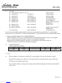
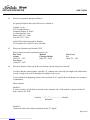
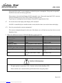
Revised Date: Feb 03, 2009
APPLICATION NOTES
Issued Date: Feb. 04, 2008
APN 1100-01
CU20025ECPB-W1J
Application Note
INDEX
1. BUS Setup
2. Initializing procedure
3. DDRAM address for CU20025ECPB-W1J
4. FAQ (Frequently Asked Questions)
5. Comparisons between U-version modules and LCDs
Noritake Co., Inc.
East Coast
Atlanta
Midwest
Chicago & Dallas
West Coast
LA
2635 Clearbrook Drive
Arlington Height, IL 60005
www.noritake-elec.com
Phone: (800) 779 – 5846
Fax: (847) 593 – 2285
(888) 326 – 3423
(800) 779 – 5846
(888) 795 – 3423
New Jersey
(888) 296 – 3423
Page 1 of 1 Downloaded from Elcodis.com electronic components distributor
APPLICATION NOTES
The
APN 1100-01
is the registered trademark of Noritake Vacuum Fluorescent Display (VFD)
This Application Note has been compiled as a support material for our customers using U-version Vacuum
Fluorescent Display Modules (described as U-version Modules in the following sections). This document
contains general product information; the user is recommended to refer to the most recent product specification.
Materials included in this document are meant to be reference data and actual results may vary.
Applicable Model:
CU20025ECPB-W1J
1. BUS Setup
1.1
M68/i80 Selection
The U-version VFD modules support an M68 interface bus (E&R /W) making it interchangeable with
LCDs. In addition, the U-version VFD can be configured to interface to i80 bus (WR/RD) via the
jumpers that are located on the printed circuit board. To short circuit the jumpers, a soldering iron will
be necessary and a sharp object such as a knife is required.
1.2
8-Bit/4-Bit Selection
In both the M68 and i80 interface modes, the data bus width can be selected for 8 bit or 4 bit operation.
The modes are switched from 8 bit to 4 bit by sending a software command. If you have chosen the 4bit mode, use the upper nibble (D7-D4). An example of the initialization sequence for each case will be
explained in detail in the next section.
2. Initializing Procedure
The U-version module has its BUS width set at 8 bits by default. The U-version allows the user to select
either 8 bits or 4 bits. 4 bits mode allows the users to take advantage of the LCD interchangeable function.
2.1
8 bit mode
(1) Wait 260m Sec. After Vcc>4.75
(2) Function Set
38H (RS=0)
(3) Function Set
38H (RS=0)
(4) Brightness Set
00H (RS=1)
(5) Display OFF
08H (RS=0)
(6) Display Clear
(7) Wait 2.3m Sec
(8) Display ON
01H (RS=0)
0CH (RS=0)
(9) Entry Mode
06H (RS=0)
: Power on reset
: 8 bit Bus Mode
: 8 bit Bus Mode
: 100% Brightness
: Display OFF, Cursor OFF
: Blinking OFF
: Display Clear Instruction
: Display ON, Cursor OFF
: Blinking OFF
: Cursor Increment
Page 2 of 2
Downloaded from Elcodis.com electronic components distributor
APPLICATION NOTES
2.2
APN 1100-01
4 bit mode
(1) Wait 260m Sec, After VCC>4.75
(2) Function Set
3xH (RS=0)
(3) Function Set
3xH (RS=0)
(4) Function Set
2xH, 8xH (RS=0)
(5) Function Set
0xH, 0xH (RS=0)
(6) Brightness Set
0xH, 8xH (RS=1)
(7) Display OFF
0xH, 8xH (RS=0)
(8) Display Clear
(9) Wait 2.3m Sec
(10) Display ON/OFF
0xH, 1xH (RS=0)
: Power on reset
: 8 bit Bus Mode
: 8 bit Bus Mode
: 8 bit Bus Mode
: Set 4 bit Bus Mode
: 100% Brightness
: Display OFF, Cursor OFF
: Blinking OFF
: Display Clear
0xH, CxH (RS=0)
: Display ON, Cursor OFF
: Blinking OFF
(11) Entry Mode
0xH, 6xH (RS=0)
: Cursor Increment
Note: In order to establish synchronization between the upper and the lower nibble, the U-version module
should be first set in 8 bit mode. To ensure synchronization, we advise that the task to be performed three times.
3. Display Data RAM Addresses for CU20025ECPB-W1J
Before writing the 2nd line on to CU20025ECPB-W1J, the RAM address pointer needs to be reassigned.
The U-version module has 80 character capacities for the display data RAM.
Modules with less than 80 displayed characters use selected area of the RAM for each row.
These selected areas are specified by the address assignment.
3.1
CU20025ECPB-W1J
Address assignment as follows:
00H
01H
40H
41H
LEFT
...................
...................
12H
52H
13H
53H
RIGHT
4. FAQ
4.1
When a character is rewritten or scrolled on U-version module, why does the character overlap?
The character overlap is not visible on a LCD due to their slow response time but can be visible on a
VFD because of its high response time.
To prevent this character overlap, when writing to the module the high period of the E signal should be
5µsec or less.
Page 3 of 3
Downloaded from Elcodis.com electronic components distributor
APPLICATION NOTES
4.2
APN 1100-01
Where can I purchase the Optical Filters?
Pre packaged Optical Filter and VFD set are available at:
Noritake Co.,Inc.
2635 Clearbrook Drive
Arlington Heights, IL 60005
www.noritake-elec.com
Phone: (800) 779 – 5846
Fax: (847) 593 – 2285
Optical Filter information can be found at:
www.noritake-elec.com/NTC/color_filter.htm
4.3
Where can I purchase the Noritake VFD?
Please contact our sales representatives near you
East Coast
Midwest
Atlanta
Chicago & Dallas
(888) 326 – 3423
(800) 779 – 5846
New Jersey
(888) 296 – 3423
4.4
West Coast
LA
(888) 795 – 3423
Why do 4 characters show up on the screen when only one character is entered?
It is likely that the control signals, especially “E” contains noise caused by the length of the cable and as
a result, a single write cycle is interpreted as multiple write cycles.
To prevent this from happening, observe the waveform of “E” signal with an oscilloscope for overshoot
or undershoot.
Other solutions:
Method 1:
A series resistance of 100 ohms is inserted on the controller side. If the module is operated in the i80
mode, insert it for “WR”.
Module
Controller
Resistance
Method 2:
Connect the cable with a diode termination on the “E” Signal.
Page 4 of 4
Downloaded from Elcodis.com electronic components distributor
APPLICATION NOTES
APN 1100-01
A resistor with a value of 100 to 200 ohms is connected at ground. Resistor with value of 200 to 600
ohms is connected at 5V.
OR
Note: High speed controller function can distort the waveform causing the signals to be processed as
multiple signals.
4.5
Comparison of In-Rush Current
The in-rush current for the CU20025ECPB-W1J follows:
Product Model
CU20025ECPB-W1J
Rush Current, Peak value (A)
Approx. 1.5
Sustained Period (ms)*
Approx. 0.4
* Sustained time is measured from the time in-rush current starts and until it falls to half the peak value.
4.6
Sleep Mode – Reducing the Power Consumption
Page 5 of 5
Downloaded from Elcodis.com electronic components distributor
APPLICATION NOTES
APN 1100-01
Sleep mode allows the U-version modules to reduce the power consumption. Sleep mode is especially
beneficial when used in a battery application.
Sleep mode is activated when Display On/Off command is sent. Sleep mode stops the DC/DC converter
and cut-off filament power to the VFD, resulting in longer tube life.
Typical power consumption when the display is turned off is approximately 5mA.
4.7
Do I need to detect the display after Display OFF command?
ON/OFF is controlled by the controller not the circuit, therefore there is no need to detect the display.
4.7.1
How do you monitor the current consumption?
The current consumption depends on the state of the display, on or off and can vary from 5mA to several
hundreds of mA.
5. What is the difference between CU20025ECPB-W1J module and LCD
CU20025ECPB-W1J
BUS Interface
M68 and i80
CG RAM SIZE
320 bit
CGROM Font
240 characters
No. of Lines
2 lines
Brightness Control
4 level brightness control function
Address / Data hold time
Min 700ns
RS, R/W set up time
Min 20ns
Data Delay From “E” and “WR”
Max 160ns
Execution Time
Faster than LCD except “Display
Clear”
Reset
C/R delay reset circuit. 100ms
typical
LCD General
M68 only
512 bit
192 characters
1 line or 2 lines
Min 20ns
Min 140ns
Max 320ns
Slower than LCD except “Display
Clear”
No delay circuit
Safety Information
The glass portion is exposed on VFD. Caution is advised when handling VFD.
Please read the user’s manual and the specifications before using the product.
Page 6 of 6
Downloaded from Elcodis.com electronic components distributor