1
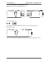
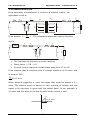
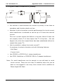
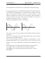
USER’S MANUAL
V1 - Rev. 01/2002
APPLICATION NOTES
TRANSFORMERS
CD Automation S.r.l.
Via F.lli Cervi, 42/44
20020 Cantalupo di Cerro Maggiore (MI) - Italy
Tel +39 0331 533512 – Fax +39 0331 533516
e-mail: [email protected]
web: www.cdautomation.com
C.D. Automation srl
Application Note – Transformer V1.0
Index:
1.
GLOSSARY
2
2.
PRINCIPLES
3
3.
THE TRASFORMER
4
3.1 REAL TRANSFORMER
5
3.1.1 INDICATIVE VALUE FOR REALISTIC TRANSFORMER
6
3.2 THE TRANSFORMER AND EQUVALENT CIRQUIT
7
3.3 UNLOAD TRANSFORMER
8
3.4 LOADED TRANSFORMER
10
3.5 TRASFORMER WORKING IN SHORT CIRCUIT
11
3.6 TRANSFORMER WORKING IN SATURATION
12
3.7 FORMULAS
13
3.8 THREE PHASE TRANSFORMER
15
4.
THYRISTOR STACKS TO DRIVE TRANSFORMER
16
4.1 THYRIASTOR STACK CONNECTED BETWEN SECONDARY AND LOAD
17
4.2 THYRIASTOR STACK CONNECTED BETWEN PRYMARY
18
4.3 THYRIASTOR STACK CONNECTED TO PRYMARY USING BURST FIRING(BF)
19
4.4 CD AUTOMATION UNIT TO BE USED
23
4.5 APPLICATION WITH THREE PHASE TRANSFORMERS
24
4.6 SCOTT TRANSFORMERS
25
4.7 WHY USE THYRISTOR UNIT IN FOURNACE
27
1
www.cdautomation.com
C.D. Automation srl
Application Note – Transformer V1.0
1. GLOSSARY
r1:
Primary windings resistance
r2:
Secondary windings resistance
re:
Primary windings resistance plus Secondary windings resistance
seen from the primary
RL:
Load Resistance
x1:
Primary leakage inductance
x2:
Secondary leakage inductance
xe:
Primary leakage inductance plus Secondary leakage inductance seen
from the primary
Z1:
Primary impedance consisting of the vectorial sum of r1 and x1
V1 :
Primary voltage
V2 :
Secondary voltage
I1:
Primary current
I2:
Secondary current
Im:
Magnetizing current generating the flux
Ip:
Eddy current in laminations (core losses)
Iϕ:
Vectorial sum of Im + Ip also called magnetizing current since Im>Ip
on power transformer
m1:
Number of winding on primary
m2:
Number of winding on secondary
f:
Voltage frequency
c1:
Electromagnetic force on primary
c2:
Electromagnetic force on secondary
www.cdautomation.com
2
C.D. Automation srl
Application Note – Transformer V1.0
2. PRINCIPLES
How works a transformer?
The principle on which works the transformer is based on general low of
electromagnetic induction
e=−
dϕ
dt
The magnetizing current generate a magnetic flux that is concatenated
with the secondary.
This flux is variable on time and it is sinusoidal, on secondary circuit that
is metallically insulated from primary is inducted on electromagnetic
voltage that give a voltage between the secondary terminals.
If we apply to primary a D.C. voltage the transformer does not work.
Infact the derivative of a constant value is zero, so “e” became zero.
3
www.cdautomation.com
C.D. Automation srl
Application Note – Transformer V1.0
3. THE TRANSFORMER
Φ
I1
I2
Φ1
Φ2
M2
M1
V2
R2
Transformers are used to modify parameters of electric power. They
receive energy with a certain value of voltage and current( primary of
transformer) and they delivery a voltage on secondary that is K time
bigger in voltage and K time lower in current or vice versa.
The apparance of the transformer are below represented
V1 = M 1
→
dΦ
→
dt
V1 M 1
=
V2 M 2
V2 = M 2
dΦ
→
dt
t
Φ=
1
V(0 ) dt →
M1
∫
0
→ V1 I 1 = V2 I 2
www.cdautomation.com
4
dΦ
V1
dt
=
dΦ
V2
M2
dt
M1
→
C.D. Automation srl
Application Note – Transformer V1.0
3.1 Real transformer
The transformer represented in the precedent paragraph is an ideal
transformer.
In a real transformer there is a power dissipation and flux dissipation.
Heating from
winding 1
Heating from
magnetic circuit
Heating from
winding 2
I2
I1
P1
P2
Q1
V2 Q 2
V1
Flux dispersion
on secondary
Flux dispersion
on primary
Coupling flux
The balance of power is represented above .
If we consider the principle of preservation of energy and in first
hypothesis we don’t consider power los.
P1 ≅ P2
Q1 ≅ Q2
V1 I 1 ≅ V2 I 2 ⇒
A1 ≅ A2
V1 I 2
=
V2 I 1
V1
= K Voltage Ratio
V2
V1 = V2
I2
= V2 K
I1
I1 =
I2
= K Current Ratio
I1
1
I2
K
5
www.cdautomation.com
C.D. Automation srl
Application Note – Transformer V1.0
3.1.1 Indicative value for realistic transformer
Heat from core
≅ 1÷5% of Input Power
Heat from winding
≅ 1÷5% of Input Power
Leakage fluxes
≅ 1÷10% of Flux φ
Efficiency η
≅
Noise
≅
www.cdautomation.com
90 ÷ 97% Depending on nominal power. With big
transformers the efficiency is very high ∼ 97%
20 ÷ 60dB Depending on magnetostriction of
lamination and windings vibration
6
C.D. Automation srl
Application Note – Transformer V1.0
3.2 The transformer and equvalent circuit
Equivalent circuit of a loaded transformer
r1
I1
x1
r2
m2
m1
I2
x2
I0
Ip
In
V1
E1
E2
V2
In a ideal transformer
E1 M 1
=
E2 M 2
E2 =
M2
E1
M1
If we assume that that transformer has K=1 we have the following
equivalent circuit.
r1
r2
x1
x2
I0
Ip
In
V1
V2
RL
This circuit is used in next pages to have more intuitive equivalent circuit.
7
www.cdautomation.com
RL
C.D. Automation srl
Application Note – Transformer V1.0
3.3 Unloaded transformer
Equivalent circuit of a unloaded transformer
r1
I1=0
x1
m2
m1
I2=0
r2
x2
I0
Ip
In
V1
E1
E2
ϕ0 ≅ 90°
x1I0
V1
cos ϕ0≅ 0
r1I0
-E1
ϕ0
I0
Ip
Iµ
E2
E1
We can simplify the circuit assuming K =
M2
= 1 . The unloaded
M1
transformer seen by thyristor unit is
I0
Ip
Iµ
V1
this means to have secondary open and to apply voltage on primary.
www.cdautomation.com
8
V2
C.D. Automation srl
Application Note – Transformer V1.0
The magnetizing current I 0 = I µ + I p and there a pick of current that is
normally bigger than nominal current. The fuses blow.
I '1 =
1
Vdt
x1
∫
In this case the thyristor unit see the transformer as a pure inductive load.
Very close to 90° delay.
V1
cos ϕ close to 0
ϕ0
I0
I0
B(t)
Φ(t)
Φ(t)
V(t)
t
Im(t)
H(t)
V(t)
Φ(t)
I0
t
To avoid to have the pick current I0 can be used two technique:
1. Phase angle firing with soft start and current limit
2. Burst firing using the Delay Triggering (DT) technique.
To avoid magnetic circuit saturation, the thyristor unit switch OFF
when load voltage is negative and switch ON only when is positive
with a setted delay on voltage zero crossing. In this way is possible
to switch ON when current is zero.
9
www.cdautomation.com
C.D. Automation srl
Application Note – Transformer V1.0
3.4 Loaded transformer
If the secondary of transformer is closed on a resistive load RL, the
equivalent circuit is:
r1
I1
x1
r2
m2
m1
I2
x2
I0
Ip
In
V1
E1
If we assume K =
E2
V2
M2
= 1 . The unloaded transformer seen by thyristor
M1
unit is
r1
r2
x1
x2
I0
Ip
Iµ
V1
V2
RL
•
The load seen by thyristor is mostly resistive
•
Power factor ≅ 0.8 ÷ 0.9
•
In burst firing is required a small phase delay from 15 to 40°.
If we consider that a complete cycle of voltage waveform is 20 msec. and
is equal to 360°
20
40 ≅ 2,1m sec
360
When delayed triggering is used, the delay that must be setted is 2,1
msec. The electric circuit is based on zero crossing of voltage and the
signal to fire thyristor is given with the setted delay. In our example is
2,1msec and this allow to fire the thyristor when current is zero
V
40°=2,1msec
I
.
www.cdautomation.com
10
RL
C.D. Automation srl
Application Note – Transformer V1.0
3.5 Trasformer working in short circuit
Short circuit voltage Vsc is the value of voltage on primary able to give a
circulating current equal to nominal with the secondary terminals in short
circuit.
In normal transformer is 5% of V1.
This means that if is done a short circuit on secondary with nominal
voltage on primary the circulating current becomes 20 times the nominal
one.
r1I0
r1
x1I0
x1
r2
x2
I0
Ip
Iµ
V1
V2=0
If for example Vsc is 5% this means that also E1 is 5% and the flux is
small.
The power loss are small and negligible because are proportional to
(0,05)2=0,025
Of nominal value when the transformer is loaded
The equivalent circuit assuming K =
r1
M2
= 1 is:
M1
r2
x1
x2
I0
Ip
Iµ
V1
V2
The current is limited only by impedance of primary an secondary winding.
•
Vsc = 5% of V1
•
Isc is 20 time the nominal current with full voltage
•
Power factor ≅ 0.7 ÷ 0.8
•
Current limited by winding impedance only
•
Leakage inductance is equivalent to an air coil it does not saturate
11
www.cdautomation.com
C.D. Automation srl
Application Note – Transformer V1.0
3.6 Transformer working in saturation
I1
r1
r2
x1
x2
V1
This circuit is simplified considering K =
M2
=1
M1
•
The current I1 is limited by r1 x1 only
•
The fuse of thyristor unit will blow and if is not properly sized for i2t
will blow also the thyristors
•
A normal transformer must never saturate
•
To avoid to have saturation, positive and negative must be equal.
Other ways a dc component will appear.
a
DC component
t
b
a>b
(a-b)/20 = DC component average value
www.cdautomation.com
12
C.D. Automation srl
Application Note – Transformer V1.0
3.7 Formulas
PLOSS
I1
I2
P1
V1
PL
V2
PL
Data
Incognita
V1=400V
I1= ??
V2=100V
KVA=100
PL=80KW
Solution 1
V1 I 1 = V2 I 2
400 * I 1 = 100 * 800
PL = V2 I 2
I1 =
100 * 800
= 200 A
400
I2 =
80.000
= 800 A
100
I2 =
PL
V2
Solution 2
V1
=K
V2
400
=4
100
I2
=K
I1
I1 =
1
I2
K
I1 =
1 80.000
= 200 A
*
4
100
The maximum current on primary is:
Pno min al ( KVA) = V1 I 1
I1 =
Pn ( KVA)
V1
=
100.000
= 250 A
400
We suggest to size the thyristor unit for 250A because in future is possible
to add other loads.
13
www.cdautomation.com
C.D. Automation srl
Application Note – Transformer V1.0
Solution 3
This is the easier solution based on balance of power
P1 = PLOSS + PL
We consider PLOSS negligible
P1 ≡ PL
P1 = V1 I 1
I1 =
P1 80.000
=
= 200 A
V1
400
www.cdautomation.com
14
C.D. Automation srl
Application Note – Transformer V1.0
3.8 Three phase transformer
I1
I2
V2=100
V1=400
P1
100KW
100KW
PL
100KW
Data
Incognita
V1=400V
I2= ??
V2=100V
PL=300KW
PL ≡ 100 + 100 + 100
To found total power it’s possible to do arithmetical sum (boucherout low).
With 3 phase loads we don’t suggest to use solution 1-2 used for 1 phases
transformer because K value depend on the different connection on
primary and secondary
Y/∆ - ∆/∆ - Y/Y - ∆/Y etc.
Solution
P1 = PLOSS + PL
We consider PLOSS negligible
P1 ≡ PL
P1 ≅ 3V1 I 1
I1 =
P1 ≅ 1,73 * V1 I 1
P1
300.000
=
= 433 A
1,73*V1 1,73* 400
15
www.cdautomation.com
C.D. Automation srl
Application Note – Transformer V1.0
4. THYRISTOR STACKS TO DRIVE TRANSFORMER
We have seen in previously pages that one transformer is used for
following purposes:
•
To have galvanic isolation between primary and secondary
•
To adapt the main supply voltage to the nominal load voltage
Ex.: main supply 400V, load supply 60V,
you need a tranformer 400/60V
www.cdautomation.com
16
C.D. Automation srl
Application Note – Transformer V1.0
4.1 Thyristor stack connected betwen secondary and load
I1=25A
V1=400A
•
I2=200A
Load
10KW
V2=50V
Normally this solution is not used because the current of secondary
is higher than primary. In our example I1=25A I2=200A. It’s easy to
understand that one unit of 200A cost a lot more than one of 25A
•
Advantage of this connection is that no attention must be paid to
the transformer but just to the load features.
In this case we can use a normal zero crossing firing.
Ex: CD3000S or CD3000A or CD3000M without option.
•
Same consideration for three phase load and is this case the
thyristor units will be CD3000A-2PH or CD3000A-3PH.
If you need communication use M family.
17
www.cdautomation.com
C.D. Automation srl
Application Note – Transformer V1.0
4.2 Thyristor stack connected on primary
I1=25A
I2=200A
Load
V2=50V 10KW
V1=400A
•
this solution is used because the current on primary is less than on
secondary and thyristor stack cost less
•
Attention to this connection must be paid because the inrush current
when transformer is switched on can be up to 20 times the nominal
current.
This over current causes fuse failure or thyristor failure if fuses are
not properly sized (i2t of fuse higher that i2t of thyristor , this can
happen only when the original fuses has been substituted without to
respect the proper i2t)
•
How is possible to reduce the inrush current??
Is necessary to select a thyristor unit with following features:
- Soft-Start
- Current Limit
•
Use CD3200 or CD2200 for 1 phase transformer
•
Use CD30, Multidrive or CD3000E-3PH for 3 phases transformer.
Note: For small transformer can be enough to use soft-start to avoid
inrush current. There are not rules to establish when this can be
done so we suggest to use every time current limit in addition to
Phase Angle Soft Start
www.cdautomation.com
18
C.D. Automation srl
Application Note – Transformer V1.0
4.3 Thyristor stack connected on primary using Burst Firing (BF)
This firing mode is used to switch ON-OFF a transformer on primary.
I1
I2
V1
V2
RL
With this circuit the power is controlled in non continuous mode.
The firing technique used is Burst Firing (BF)
Ex.:
If we set Power at 50% = 4 Cycles ON – 4 Cycles OFF
we will have at 75% = 12 Cycles ON – 4 Cycles OFF
(see Duty Cycle Tecnique in application note)
This technique allows to use zero crossing avoiding to have electrical noise
and interference typical of Phase Angle Firing.
Unfortunately Burst Firing used on primary transformer generate an inrush
current in the transformer able to blow fuses.
To avoid this problem CD Automation uses a technique named “Delay
Triggering” (DT).
The most important features of this firing are :
Switch OFF when current is negative and goes to 0
Switch ON when current is zero and immediately after became positive.
V(t)
I0
t
CD Automation thyristor units with Delayed Triggering switch OFF when
voltage is negative and switch ON only when voltage is positive, this
19
www.cdautomation.com
C.D. Automation srl
feature
is
Application Note – Transformer V1.0
necessary
to
avoid
saturation
of
magnetic
circuit
of
transformers.
To understand we have refer to the curve of Flux Intensity(B) related to
Ampere Turns m1xI1(H).
It’s important to consider that the current is not in phase with voltage but
has a delay. The electronic circuit detect the zero voltage but when the
voltage is zero the current has a negative value.
y
V(t)
I0
V
I’1
•
45°
x
t
I1
The instantaneous value is the projection on y axis I’1 that is a
negative value that is in same direction of residual flux and allow
excess current to flow with consequent fuse failure. The technique
used is to switch ON after a delay time from the V1 zero crossing.
•
The vectors are rotating anticlockwise. Complete rotation of 360°
that is complete period. One period is 20msec at 50Hz.
Thus if delay of current is 45° the unit must switch ON with a delay.
360
20
=
45
X delay
www.cdautomation.com
X delay =
20 * 45
= 25 m sec
360
20
C.D. Automation srl
Application Note – Transformer V1.0
B
Negative
magnetising
current
Residual positive with H=0
Residual negative with H=0
H
Positive
magnetising
current
In magnetic circuit there is a residual magnetism that can be positive or
negative depending on when the current was switched OFF. If we have
residual flux positive and we switch ON when the current is positive we
have the magnetic saturation due the sum of (residual positive + flux
positive). In this case the current rise and fuses blow.
If we switch OFF negative the residual flux is negative and switching ON
positive the total flux is smaller than normal one.
Residual flux + flux positive < Normal flux.
In this mode we have no saturation.
21
www.cdautomation.com
C.D. Automation srl
Application Note – Transformer V1.0
y
V1
I1
x
Delayed angle depend on the feature of the transformers with delay of 2,5
msec we switch ON when current is zero and after which becomes
positive.
Residualnegative + Flux positive = Flux value below nominal.
In this case there are no problems for saturation and there is no inrush
current. The fuses does not blow.
www.cdautomation.com
22
C.D. Automation srl
Application Note – Transformer V1.0
4.4 CD Automation unit to for one phase applications
For this application use CD3000A or M configured for delayed triggering.
For 3 phase application use: CD3000E-2PH configured for delay triggering.
On CD3000E the enhanced type of CD3000 family is possible to set the
delay of firing and the number of half cycle on which to apply it. In the
majority of transformer is enough to set one half cycle. When the delay is
not known because we don’t know the angle between the vectors of
voltage and current set 2,5msec = 45° delay.
The delay is adjustable from zero to 90°(5msec).
V
V
I45°
I90°
I45°
t
2,5ms
t
The inrush current will be minimized and the benefits of Burst Firing will
be realised.
The use of this technique has been experimented with normal resistive
loads and silicon carbide elements.
Don’t use this technique with cold resistance like KantalSuper or other
resistance that have a very low value when cold. In this case for the
thyristor unit is like to switch ON a transformer with secondary in short
circuit.
For this application use Phase Angle with Soft Start and current limit.
The suggest unit for one phase loads are CD2200 or Cd3200.
The suggest unit for three phase loads are CD3000E-3PH , CD30 or
MULTUDRIVE.
23
www.cdautomation.com
C.D. Automation srl
Application Note – Transformer V1.0
4.5 Application with three phase transformers
It’s important to keep in mind that the tree limb fluxes must be equal by
maintaining the three voltage on primary equal with Phase Angle Firing.
This means that if the loads on each phase are equal also the currents will
be equal and viceversa. If loads are unequal and customer want to adjust
the voltage to equalise the power in the 3 zones is not easy and can be
done just with cautions and for small percentage. Avoid to do it is too
dangerous. This means that a three phase transformer
can not be
treaded like three one phase transformers because there is an interaction
between the phases.
A extra complication are the harmonics generated by phase angle. To
maintain the harmonics inside the transformer is used a delta connection
on primary. The current in the windings consist of a range of harmonics in
addition to the fundamental current. The effect of the harmonics an a core
transformer is an overheating on the transformer core and on metallic
steel case because the lost fluxes try to close via any metals in the
vicinity. With delta connection the flux of the harmonics will add in a ring
round the core with a resultant of zero.
Anyway in the field three applications where the primary is a star
connection. Despite the guideline these applications are working with
satisfaction probably because the transformers are lightly loaded and
designed to work with low induction. One of the rules used by CD
Automation when a transformer is ordered is:
•
Increase the nominal power of the transformer of 20%
•
Increase the nominal value of primary and secondary voltage of
10%.
The transformer ratio remain the same but the transformer works
at low value of induction..
www.cdautomation.com
24
C.D. Automation srl
Application Note – Transformer V1.0
4.6 Scott transformers
The Scott-wound Transformer is designed to have one three phase
primary (normally star connected) and two one phase secondaries.
2nd secondary
1 secondary
th
This type of transformer is not very popular but there are application
where there are two zones and is necessary to balance the load on the
three phases. The solution is a Scott-Transformer.
Typical applications are two zone furnaces and salt baths where, for
supply reasons, energy for only two zones is taken from a three phase
main voltage supply.
All the attentions paid for normal three phase transformers must be used
also for Scott Winding Transformer.
Flux patterns are more critical than in normal transformers and so it’s
necessary to use a longer soft start.
It’s suggested to have a Soft Start (Ramp) of 2 sec minimum.
In this application must be used Phase Angle and the harmonic content in
load current are reflected on primary and on primary star connected the
current on the three limbs can be different.
25
www.cdautomation.com
C.D. Automation srl
Application Note – Transformer V1.0
Another precaution is to use thyristor rated 1600V (reverse pick voltage)
because can happen to have parasite voltage that damage Thyristers
when are in off conditions. This happens when
the secondary are not
galvanically isolated.
If supply voltage is 400V use thyristor unit for 500V that as standard uses
1600V RPV. The Scott Transformers must work at low induction value 1
Wb/m2
A good practice is also to use on primary a filter rated for 50 Hz.
The CD Automation Thyristor units to drive Scott Transformer are:
•
CD30
•
MULTIDRIVE
www.cdautomation.com
26
C.D. Automation srl
Application Note – Transformer V1.0
4.7 Why use thyristor unit in fournace
Electrical powered fournaces are becoming more important mainly for
these reasons:
a) Clean ambient inside furnace;
b) Very high efficiency;
c) High capacity to maintain a stable temperature over a wide range of
set points;
d) Capacity to optimising temperature uniformity;
Anyway to maintain points c) and d) using contactors is necessary to use
a temperature cycle time of 20 sec. This means that at 50% power
demand, that is a normal working condition after the Start up of the
furnace, the contactors switch ON every 20 sec. and in one day 4.320
times considering 24 hours (normally furnaces don’t stop)
In one year there are 320 working days:
total switches Æ4320 x 320= 1.382.400
After 0,5 million of operation the contacts of contactor must be
substituted. This is a big cost because:
-
Every month the contacts done with precious metals have to be
substituted.
The cost of a medium size contactor 200A is 150 Euro;
-
Every year the contactor has to be substituted because the mechanical
life is finished. The 200A contactor cost is 500 Euro
-
in addition when service or maintenance are done, there is a stop
of the production with relative costs.
27
www.cdautomation.com
C.D. Automation srl
Application Note – Transformer V1.0
THYRISTOR UNITS
•
The thyristor units are more expensive than contactor.
•
The payback is very short because there are no maintenance or
service costs and the life of one thyristor unit can be 10 years.
•
In addition is also possible to use a cycle time very short (up to
20msec ON and 20 msec OFF this firing is known as Single Cycle
very useful with low interthia systems). For Burst Firing see our
application note on Firing modes available on CD Automation
thyristor units.
•
With Thriystor units is possible to adjust the power on different
zones when are controlled by one temperature control only.
SCR
SCR
SCR
A
B
C
The output of the controller is a power demand from the process. If above
process is a furnace and heating elements A – B – C are equal, but the B
is central and has a lower heating losses, we can decide to send the same
signal to A and C loads and to reduce the power with a devider of input
signal on zone B. This can be done in digital mode on CD3000A-M family
and Multidrive
www.cdautomation.com
28