1
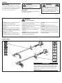
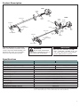
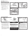
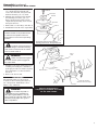
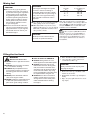
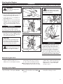
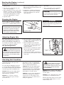
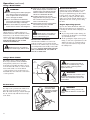
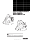
English................1
Español.........SP_1
Françias........FR_1
SHINDAIWA OWNER’S/OPERATOR’S MANUAL
T282 TRIMMER
T282X TRIMMER
T282
T282X
WARNING!
Minimize the risk of injury to yourself and others! Read this
manual and familiarize yourself with the contents. Always wear
eye and hearing protection when operating this unit.
Part Number 89027 Rev. 11/08
Introduction
The Shindaiwa 282 series is designed and
built to deliver superior performance and
reliability without compromise to quality,
comfort, safety or durability.
Shindaiwa engines represent the leading
edge of high-performance engine
technology, delivering exceptionally high
power with remarkably low displacement
and weight. As an owner/operator, you’ll
soon discover for yourself why Shindaiwa
is simply in a class by itself!
Contents
IMPORTANT!
The information contained in these instructions describes units available at the time
of publication.
Shindaiwa Inc. reserves the right to make
changes to products without prior notice,
and without obligation to make alterations
to units previously manufactured.
PAGE
Safety............................................................3
Product Description....................................5
Specifications...............................................5
Assembly......................................................6
Mixing fuel.................................................10
WARNING!
The engine exhaust from this
product contains chemicals known to
the State of California to cause cancer, birth defects or other reproductive harm.
PAGE
Filling the fuel tank...................................10
Starting the Engine . ................................11
Stopping the Engine.................................12
Adjusting Engine Idle...............................12
Checking Unit Condition.........................12
PAGE
Operation...................................................13
Maintenance..............................................15
Long Term Storage...................................18
Troubleshooting Guide............................19
Emission System Warranty Statement...22
IMPORTANT!
The operational procedures described in this manual are intended to help you get the most from this unit as well as to protect you and
others from harm. These procedures are guidelines for safe operation under most conditions, and are not intended to replace any safety
rules and/or laws that may be in force in your area. If you have questions regarding your 282 Series, or if you do not understand something in this manual, contact your local authorized Shindaiwa dealer. You may also contact Shindaiwa Inc. at the address printed on the
back of this Manual.
Attention Statements
Throughout this manual are special “attention statements”.
DANGER!
A statement preceded by the
triangular attention symbol and the
word “DANGER” contains information
that should be acted upon to prevent
serious injury or death.
WARNING!
CAUTION!
A statement preceded by the
triangular attention symbol and the
word “WARNING” contains information
that should be acted upon to prevent
serious bodily injury.
A statement preceded by the word
“CAUTION” contains information
that should be acted upon to prevent
mechanical damage.
IMPORTANT!
A statement preceded by the word “NOTE”
contains information that is handy to know
and may make your job easier.
A statement preceded by the word
“IMPORTANT” is one that possesses special significance.
NOTE:
Warning and Operational Labels
50 FEET
(15m)
2
Read and follow this operator's
manual. Failure to do so could
result in serious injury..
Beware of thrown or
richocheted objects
Always wear a harness when
operating this unit with a blade.
A harness is also recommended
when using trimmer line.
Wear eye and hearing protection
at all times during operation of
this unit. Wear head protection
where there is a risk of falling
objects.
DO NOT use this unit with
a blade!
If unit is used as a brushcutter,
beware of blade thrust. A jammed
blade can cause the unit to jerk
suddenly and may cause the operator to lose control of the unit.
Make sure no one is within
15 M / 50 feet of an operating machine.
8”
BARRIER
DO NOT operate this unit with a
blade unless the unit is equipped
with a Shindawia-approved handlebar or barrier.
Muffler, muffler cover and surrounding area will be high in temperature.There is risk of getting
burned.
Safety
Work Safely
WARNING!
Trimmers and brushcutters operate at
Never make unauthorized
very high speeds and can do serious damattachment installations.
age or injury if they are misused or abused.
Never allow a person without training or
Stay Alert
instruction to operate this unit!
You must be physically and mentally fit to
operate this unit safely.
WARNING!
Never operate
power equipment of any kind
if you are tired or if you are under the
influence of alcohol, drugs, medication or any other substance that could
affect your ability or judgement.
WARNING!
Use Good Judgment
ALWAYS inspect unit before each use.
Replace any damaged parts.
Inspect for broken, missing or improperly
installed parts or attachments.
ALWAYS use the proper cutting tool for
the job.
NEVER run the engine when transporting the unit.
NEVER extend trimming line beyond the
length specified for your unit.
ALWAYS keep the handles clean.
NEVER run the engine indoors! Make
sure there is always good ventilation.
Fumes from engine exhaust can cause
serious injury or death.
ALWAYS keep the unit as clean as practical. Keep it free of loose vegetation,
mud, etc.
ALWAYS stop the unit immediately if
it suddenly begins to vibrate or shake.
ALWAYS hold the unit firmly with both
hands when cutting or trimming, and
maintain control at all times.
ALWAYS disconnect the spark plug wire
before performing any maintenance work.
ALWAYS, if a saw blade should bind fast
in a cut, shut off the engine immediately.
Push the branch or tree to ease the bind
and free the blade.
Safety Labels
READ THE
OPERATOR’ S M ANUAL
WEAR HEARING AND ANSI Z8 7 .1
APPROVED EYE PROTECTION
50 FEET
(15m)
T282
KEEP BYSTANDERS AWAY
AT LEAST 5 0 FEET (1 5 m)
BEWARE OF THROWN OR
RICOCHETED OBJECTS
DO NOT OPERATE THIS
M ACHINE WITH A BLADE
Shindaiwa Inc.
19422-00028
T282X
IMPORTANT!
Safety and Operation Information Labels: Make sure all
information labels are undamaged and readable. Immediately replace damaged or missing information labels.
New labels are available from your local authorized
Shindaiwa dealer.
3
Safety (continued)
The Properly Equipped Operator
Wear hearing protection devices and a
broad-brimmed hat or helmet. A helmet
is required when using a blade-equipped
brushcutter to clear small trees.
Always wear eye protection such as
goggles or safety glasses to shield
against thrown objects.
Always wear a harness when operating the unit .
It adds comfort and helps ensure safety by limiting
movement fore and aft. When the harness is
adjusted properly, the unit should balance with the
cutting attachment parallel to the ground.
Prolonged exposure to excessive noise
is fatiguing and could lead to impaired
hearing.
Always operate with both hands
firmly gripping the unit.
Wear close-fitting clothing to
protect legs and arms. Gloves
offer added protection and are
strongly recommended. Do not
wear clothing or jewelry that
could get caught in machinery
or underbrush. Secure long hair
so that it is above shoulder level.
NEVER wear shorts!
When operating with a blade, make sure
the handle is positioned to provide you with
maximum protection from contacting the
blade. Always make sure the handlebar
is installed in accordance with the
manufacturers instructions.
Always make sure the
appropriate cutting attachment
shield is correctly installed and
in good condition. Do not
operate the unit if the
cutting attachment shield
is missing, loose, or
broken.
Long-term exposure to vibration
can damage your hands.
Keep a proper footing and do not
overreach. Maintain your balance at all
times during operation.
Keep away from the rotating
trimmer line or blade at all
times, and never lift a moving
attachment above waist-high.
Wear appropriate footwear (non-skid
boots or shoes): do not wear opentoed shoes or sandals. Never work
barefooted!
Be Aware of the Working Environment
Avoid long-term
operation in very hot
or very cold weather.
Reduce the risk of bystanders
being struck by flying debris. Make
sure no one is within 15 meters
(50 feet)— that’s about 16 paces
of an operating attachment. Stop
immediately if a child, pet, or person
comes within a 15 meter (50 feet)
radius. Outside this radius, there is still
a risk of injury from thrown objects.
Make sure
bystanders or
observers outside the
15 meter (50 feet)
“danger zone” wear
eye protection.
15 METERS
(50 FEET)
Be extremely careful
of slippery terrain,
especially during rainy
weather.
Always make sure
the appropriate
cutting attachment
shield is correctly
installed.
Be constantly alert for
objects and debris that
could be thrown either
from the rotating cutting
attachment or bounced
from a hard surface.
If contact is made with a hard object,
stop the engine and inspect the cutting
attachment for damage.
4
Do not operate the unit
if the cutting attachment
shield is missing, loose,
or broken.
15m
(50ft)
Beware of a coasting
blade when brushcutting or
edging. A coasting blade
can injure while it continues
to spin after the throttle
trigger is released or after
the engine is stopped.
ALWAYS clear your work area of trash
or hidden debris that could be thrown
back at you or toward a bystander.
When operating in rocky terrain or
near electric wires or fences, use
extreme caution to avoid contacting
such items with the cutting attachment.
Product Description
T282
Ignition
Switch
Fuel
Tank
T282X
Throttle
Trigger
Outer Tube
Ignition
Switch
Strap
Gearcase
Cutting
Attachment Shield
Throttle
Interlock
Handle
Grip
Outer Tube
Trimmer Head
Throttle
Trigger
Barrier
Bar
Gearcase
Fuel
Tank
Hanger
Cutting
Attachment Shield
Trimmer Head
Using the illustration as a guide, familiarize yourself with your machine and its
various components. Understanding your
machine helps ensure top performance,
long service life and safer operation.
IMPORTANT!
WARNING!
Do not make unauthorized
modifications or alterations to any of
these units or their components.
The terms “left”, “left-hand”, and “LH”;
“right”, “right-hand”, and “RH”; “front” and
“rear” refer to directions as viewed by the
operator during normal operation.
Specifications
Engine Name
Engine Model
Engine Type
Dr y Weight (Without guard and strap)
Dimensions
Bore x Stroke
Displacement
Maximum Power Output
Fuel/Oil Ratio
Fuel Tank Capacity
Carburetor Type
Ignition
Spark Plug
Air Cleaner Type
Starting Method
Stopping Method
Transmission Type
EPA Emission Compliance Period*
*Specifications are subject to change without notice.
T282
T282X
S282EV
2-cycle, catalyst
5.7 kg/12.6 lb.
6.0 kg/13.2 lb
1785 x 315 x 345 mm/70.3 x 12.4 x 13.6 in. 1790 x 375 x 330 mm/70.5 x 14.8 x 13 in.
1.38 x 1.18 in./ 35 x 30 mm
28.9 cc/1.7 cu. in.
1.4 HP (1.0 kW) @ 8000 (min-1)
50:1 with ISO-L-EGD or JASO FD class 2-cycle mixing oil*
750 ml/25.4 oz..
Walbro, WYK, diaphragm-type
One-piece electronic, transistor-controlled
BPMR6A
Non-reversible foam filter element
Recoil
Slide switch
Automatic, centrifugal clutch w/bevel gear
Category A
*The EPA emission compliance period referred to on the emission compliance label located on the engine, indicates
the number of operating hours for which the engine has been shown to meet Federal emission requirements. Category C = 50 hours (Moderate), B = 125 hours (Intermediate) and A = 300 hours (Extended)
5
Assembly
This unit comes fully assembled with the
exception of the cutting attachment shield
and cutting attachment.
■■Kit containing cutting attachment
Prior to Assembly
Before assembling, make sure you have all
the components required for a complete
unit and inspect unit and components for
any damage.
■■Engine and shaft assembly
■■Cutting attachment shield
■■Cutting attachment
shield, mounting bracket and hardware,
this owner’s/operator’s manual and tool
kit for routine maintenance. Tool kits
vary by model and may include a spark
plug/screwdriver combination wrench,
and a scraper.
Handle and barrier bar X unit
The handle is attached at the factory and
positioned vertically.
Handle
1. Loosen socket headed capscrew at the
base of handle and rotate the handle 90
degrees.
NOTE:
Handle
Outer Tube
Keep handle forward of handle positioning label!
2. Position the handle forward of the Handle
Positioning Label at the best position for
operator comfort (usually about 254 mm
(10 inches) ahead of throttle housing).
3. Tighten the socket headed capscrew
securely.
6
Hanger
Throttle
Assembly
Barrier Bar
Handle Positioning Label
Assembly (continued)
Cutting Attachment Shield
1. Insert the cutting attachment shield
between the outer tube and the cutting
attachment mounting plate.
NOTE:
It may be necessary to loosen the retaining nut and clamp screw to adjust cutting
attachment shield mounting plate.
2. Fit the two shims and the bracket over
the outer tube and loosely install the
four socket-head screws.
3. Tighten the four socket-head cap
screws to secure the cutting attachment shield.
T282
Socket-Head
Cap Screws
Bracket
Cutting
Attachment Shield
Shim
Clamp Screw
Shim
CAUTION!
Make sure the clamp screw and
retaining nut are securely tightened
before tightening the four socket-head
cap screws.
Outer Tube
Drain
Screw
Line Cutter
Mounting Plate
Retaining
Nut
4. Attach the subshield to the cutting
attachment shield by snapping the
hooks into the hook receivers..
CAUTION!
Make sure the subshield is completely
hooked at the hook receiver.
WARNING!
NEVER operate the unit without the cutting attachment shield
installed and tightly secured!
T282X
Socket-Head
Cap Screws
Bracket
Outer Tube
Shim
Clamp Screw
Shim
Mounting Plate
Drain
Screw
Retaining
Nut
Cutting Attachment
Shield w/subshield
Line Cutter
7
Assembly (continued)
Adjust Throttle Lever Free Play
The throttle lever free play should be
approximately 4-6 mm. Make sure that the
throttle lever operates smoothly without
binding. If it becomes necessary to adjust
the lever free play, follow the procedures
and illustrations that follow.
1. Loosen the air cleaner cover knob and
remove the air cleaner cover.
2. Loosen the lock nut on the cable
adjuster.
3. Turn the cable adjuster in or out as
required to obtain proper free play.
4. Tighten the locknut.
5. Reinstall the air cleaner cover.
4-6 mm
Throttle Free
Play
Throttle Lever Free Play
Cable
Adjuster
Remove air cleaner cover
Lock Nut
Adjust as required to obtail 4-6 mm
free play
Install trimmer head T282
Retaining Plug
To install a trimmer
head onto a T282X,
first remove the shaft
bolt, bolt guard
(see the next page).
Holder
Output
shaft
1. Turn the trimmer over so that the gear
case output shaft faces UP.
2. Remove and discard the black plastic
protective cap from the output shaft.
3. Rotate the holder until the hole in the
holder aligns with the notch on the
gear case. Use the long end of the hex
wrench to lock the holder and output
shaft.
4. While holding the hex wrench, thread
the trimmer head onto the output shaft,
turning counter-clockwise. Using hand
pressure only, tighten the trimmer head
firmly on the output shaft.
8
Hex Wrench
IMPORTANT!
The trimmer head has a left-hand thread.
For removal turn the trimmer head
clockwise.
5. Remove the hex wrench.
6. Adjust the trimmer line length to reach
no further than the line cutter on the
cutting attachment shield. Trim to the
correct length if necessary.
The unit should now be
completely assembled and ready
for use with a trimmer head.
WARNING!
A standard grass trimmer with
a loop handle should NEVER be operated with blade-type attachments.
For blade use the trimmer must be fitted with a bicycle-type handlebar or
a barrier bar that is located in front
of the operator to reduce the risk of
the operator from coming in contact
with the cutting attachment (per ANSI
B175.3). When using a blade, the unit
must also be equipped with a harness
or strap.
Assembly (continued)
Installing Brushcutter Blade T282X
1. Turn the unit upside down so the gear
case output shaft is facing UP and
remove the shaft bolt, bolt guard and
holder B from the gear case shaft.
2. Align the hole in blade holder A with
the matching hole in the gear case
flange and then temporarily lock the
output shaft by inserting a hex wrench
through both holes.
3. Fit the blade over the flange on holder A.
4. Install blade holder B on the output shaft.
Shaft Bolt
Bolt Guard
Holder B
Gear Shaft
Holder A
CAUTION!
Install the blade so its printed surface
is visible to the operator when the
brushcutter is in the normal operating
position.
WARNING!
Temporarily lock the output shaft by
inserting a hex wrench through both holes
The blade must fit flat against
the holder flange. The blade mounting
hole must be centered over the raised
boss on blade Holder A.
WARNING!
Blade
Output
Shaft
Holder B must fit flush against
the blade and the splines engaged to
the output shaft.
5. Install the bolt guard and then the blade
retaining bolt. Using the combination
spark plug wrench/screwdriver, tighten
the bolt firmly in a counter-clockwise
direction.
6. Remove the hex wrench.
Blade Holder B
Hex Wrench
IMPORTANT!
Discard blades that are bent, warped,
cracked, broken or damaged in any way.
Use a sharp blade. A dull blade is more
likely to snag and thrust.
WARNING!
Do not attach any blade to
a unit without proper installation of
all required parts. Failure to use the
proper parts can cause the blade to fly
off and seriously injure the operator
and/or bystanders.
Tighten the assembly
(blade not shown for clarity)
The unit should now be
completely assembled and ready
for use with a blade.
9
Mixing fuel
CAUTION!
■■Never use any type of gasoline
containing more than 10% alcohol
by volume! Some types of gasoline
contain alcohol as an oxygenate.
Oxygenated gasoline may cause
increased operating temperatures.
Under certain conditions, alcoholbased gasoline may also reduce
the lubricating qualities of some
2-cycle mixing oils.
■■Generic oils and some outboard
oils may not be intended for use in
high-performance 2-cycle engines,
and should never be used in your
Shindaiwa engine.
CAUTION!
This engine is designed to operate
on a 50:1 mixture consisting of
unleaded gasoline and ISO-L-EGD
or JASO FD class 2-cycle mixing oil
only. Use of non-approved mixing
oils can lead to excessive carbon
deposits.
■■Use only fresh, clean unleaded gasoline
with a pump octane of 87 or higher.
■■Mix all fuel with a 2-cycle air-cooled
mixing oil that meets or exceeds ISO-LEGD and/or JASO FD classified oils at
50:1 gasoline/oil ratio.
CAUTION!
Mix and pour fuel outdoors where
there are no sparks and flames.
Examples of 50:1 mixing quantities
Gasoline
liters
2.5
5
10
20
-
1
1
1
1
2-cycle mixing oil
milliliters
50
100
200
400
ml
ml
ml
ml
IMPORTANT!
Mix only enough fuel for your immediate
needs! If fuel must be stored longer than 30
oil with fuel stabilizer is not
days and
used, it should first be treated with a fuel
stabilizer such as STA-BIL™.
Oil is a registered JASO FD classi-fied
oil and also meets or exceeds ISO-L-EGD performance requirements. Shindaiwa One is recommended for use in all Shindaiwa low emissions engines. Shindaiwa One also includes a
fuel stabilizer.
Filling the fuel tank
WARNING!
Minimize the Risk of Fire
■■NEVER smoke or light fires near the
engine.
■■ALWAYS stop the engine and allow
it to cool before refueling.
■■ALWAYS Wipe all spilled fuel and
move at least 3 meters (10 feet) from
the fueling point and source before
starting.
■■NEVER place flammable material
close to the engine muffler.
■■NEVER operate the engine without the
muffler and spark arrester screen in
place and in good working condition.
10
■■FUEL IS HIGHLY FLAMMABLE.
■■ALWAYS store gasoline in a con-
tainer approved for flammable liquids.
■■ALWAYS inspect the unit for fuel
leaks before each use. During each
refill, check that no fuel leaks from
around the fuel cap and/or fuel tank.
If fuel leaks are evident, stop using
the unit immediately. Fuel leaks must
be repaired before using the unit.
■■ALWAYS move the unit at least 3
meters (10 feet) away from a fuel
storage area or other readily flammable materials before starting
the engine.
1. Place the unit on a flat, level surface.
2. Clear any dirt or other debris from
around the fuel filler cap.
CAUTION!
Slowly remove the fuel cap only after
stopping the engine
3. Remove the fuel cap, and fill the tank
with clean, fresh fuel.
4. Reinstall the fuel filler cap and tighten
firmly.
5. Wipe away any spilled fuel before starting engine.
Starting the Engine
IMPORTANT!
Engine ignition is controlled by a two position switch mounted on the throttle housing labeled, “I” for ON or START and “O” for OFF or STOP.
WARNING!
WARNING!
Never start the engine from
the operating position.
Keep all parts of your body
away from the rotating cutting attachment and hot surfaces.
1. Slide the ignition switch to the “I” position.
2. Press the primer bulb until fuel can be seen
flowing in the transparent return tube.
3. Set the choke lever to the CLOSED position if engine is cold.
4. While holding the outer tube firmly with
left hand. Use your other hand to slowly
pull the recoil starter handle until resistance is felt, then pull quickly to start the
engine.
Primer Bulb
Slide ignition to ON
Return Tube
Press
primer bulb...
Closed
Hold
the unit
firmly...
IMPORTANT!
The primer system only pushes fuel through
the carburetor. Repeatedly pressing the
primer bulb will not flood the engine with fuel.
5. When the engine starts, slowly move
the choke lever to the “OPEN” position.
If the engine stops after the initial start,
close the choke and restart.
Move the choke lever to the
CLOSED position
CAUTION!
Do not pull the recoil starter to the
end of the rope travel. Pulling the
recoil starter to the end of the rope
travel can damage the starter.
...and pull recoil
starter handle
upward
Open
IMPORTANT!
If the engine fails to start after several
attempts with the choke in the closed
position, the engine may be flooded
with fuel. If flooding is suspected, move
the choke lever to the open position
and repeatedly pull the recoil starter to
remove excess fuel and start the engine.
If the engine still fails to start, refer to the
troubleshooting section of this manual.
WARNING!
The cutting attachment may
rotate when the engine is started!
When the engine starts
■■After the engine starts, allow the
engine to warm up at idle for 2 or 3
minutes before operating the machine.
Make sure the
attachment is clear
of obstructions!
After engine starts, move
choke to OPEN position
■■After the engine is warm, pick up the
unit and clip on the strap or harness.
See the section on "Using the Strap".
■■Advancing the throttle makes the cut-
ting attachment rotate faster; releasing
the throttle makes the attachment stop
running. If the cutting attachment continues to rotate refer to “Engine Idle
Adjustment” for engine idle adjustment procedures.
Starting a warm engine
Starting a warm engine involves all of the
steps of starting a cold engine, EXCEPT:
■■Do not press the primer bulb.
■■The choke should be in the OPEN (
position.
)
If the engine does not start, follow the
cold engine starting procedure.
11
Starting the Engine (continued)
Starting a flooded engine
1. Slide the ignition switch button to the
STOP position.
2. Disconnect the spark plug wire, and
remove the spark plug.
5. Hold the throttle control lever
depressed and crank the engine several
times to clear excess fuel from the combustion chamber.
3. If the spark plug electrodes and ceramic 6. Reinstall the spark plug and tighten it
firmly. If a torque wrench is available,
insulator are fouled or soaked with fuel,
torque the spark plug to 17–19 N·m
clean or replace the plug. For spark plug
(150- 168 lb.-in.).
specifications and gapping procedure,
refer to the “Maintenance” section.
7. Repeat the warm engine starting
procedure.
8. If the engine fails to start, consult the
troubleshooting guide provided.
CAUTION!
Incorrect spark plug installation may
cause serious engine damage!
4. Open the choke.
Stopping the Engine
Idle the engine briefly before stopping
(about 2 minutes), then slide the ignition
switch to the “O” (Engine OFF) position.
OFF
CAUTION!
A coasting blade can cause injury while
it continues to spin after the engine is
stopped or throttle trigger is released.
Maintain proper control until the blade
has completely stopped rotating.
IMPORTANT
When the unit is turned off make sure the
cutting attachment has stopped before the
unit is set down.
Slide ignition to OFF
Adjusting Engine Idle
The engine must return to idle speed
whenever the throttle lever is released.
Idle speed is adjustable, and must be set
low enough to permit the engine clutch to
disengage the cutting attachment.
Idle Speed Adjustment
WARNING!
The cutting attachment must
NEVER rotate at engine idle!
If the idle speed cannot be adjusted by
the procedure described here, return
the trimmer to your Shindaiwa dealer
for inspection.
1. Place the trimmer on the ground, then
start the engine, and then allow it to idle
2-3 minutes until warm.
2. If the attachment rotates when the
engine is at idle, reduce the idle speed
by turning the idle adjustment screw
counter-clockwise.
3. If a tachometer is available, the engine
idle speed should be final adjusted to
2,750 (±250) min-1 (rpm).
4. Carburetor fuel mixture adjustments are
preset at factory and cannot be serviced
in the field.
Idle Adjusting
Screw
Adjusting engine idle
Checking Unit Condition
NEVER operate the unit with the cutting
attachment shield or other protective
devices removed!
Use only authorized Shindaiwa parts and
accessories with your Shindaiwa trimmer.
Do not make modifications to this unit without written approval from Shindaiwa, Inc.
ALWAYS make sure the cutting attachment is properly installed and firmly
tightened before operation.
NEVER use a cracked or warped
cutting attachment: replace it with a
ser viceable one.
12
The cutting attachment may be spinning during carburetor adjustments.
Wear your protective equipment and
obser ve all safety instructions.
ALWAYS make sure the cutting attachment fits properly into the appropriate
attachment holder. If a properly installed
attachment vibrates, replace the attachment with new one and re-check.
ALWAYS stop the engine immediately
and check for damage if you strike a
foreign object or if the unit becomes
tangled. Do not operate with broken or
damaged equipment.
WARNING!
A cutting attachment shield or
other protective device is no guarantee of protection against ricochet. YOU
MUST ALWAYS GUARD AGAINST
FLYING DEBRIS!
NEVER allow the engine to run at high
RPM without a load. Doing so could damage the engine.
NEVER operate a unit with worn or damaged fasteners or attachment holders.
When transporting, make sure the engine
is not running and the blade is covered
with the blade cover.
Operation
Shoulder Strap T282X
IMPORTANT
WARNING!
Always wear a shoulder strap
when operating this unit with a blade.
Wearing a shoulder strap with a grass
trimmer can increase operator comfort
during extended periods of operation.
Strap
Adjust the shoulder strap so the shoulder
pad rests comfortably on the off-side shoulder and the cutting path of the cutting attachment is parallel to the ground. Make sure all
hooks and adjustment devices are secure.
NOTE:
Using a shoulder strap when operating
this unit with a blade allows you to maintain proper control of the unit and reduces
fatigue during extended operation.
1. Hook the strap hook to the hanger on
the outer tube.
2. Wear the shoulder strap so that the
hook stays at your right hand side.
3. Adjust the length of the shoulder strap
so that you can hold and operate the
machine comfortably.
Cutting grass with a trimmer head
Your Shindaiwa unit may be equipped with
Engine Operating Speeds
one of several Shindaiwa trimmer head mod- Operate at full throttle while cutting grass.
els, each with features for specific applicaTrimming and Mowing Grass
tions and/or operational requirements.
Hold the grass trimmer so the trimmer
NOTE:
head is angled slightly into the area to be
For proper operation, always refer to the
cut. To ensure maximum trimmer-line serinstructions accompanying the trimmer
vice life, cut only with the tip of the trimhead being used.
mer line. Cut grass by swinging the unit’s
trimmer head from left to right. Keep the
Trimmer head styles:
trimmer head horizontal.
Semi-automatic. Trimmer line is indexed
when the operator taps the trimmer head on
the ground during operation.
Manual. The operator indexes line manually with the grass trimmer stopped.
Fixed. The operator must stop the unit and
add new lengths of trimmer line manually.
Flail. This device, designed for clearing
weeds and light brush, features three nylon
blades attached to the head by pivots.
CAUTION!
Use only flexible, nonmetallic line recommended by the manufacturer. Never use, for
example, wire or wire-rope, which can break
off and become a dangerous projectile.
CAUTION!
■■ Do not push the rotating line into trees,
wire fences or any material that could
tangle or break line ends.
■■ Operation of trimmer without a cutting
attachment shield and using excessive line length can lead to premature
clutch failure.
■■Operation at low rpm can lead to
premature clutch failure.
WARNING!
Remove all objects such as
rocks, broken glass, nails, wire, or
string, which can be thrown or become
entangled in the cutting attachment.
NOTE:
Additional hardware may be required to
mount the Fixed Line or the Flail type
trimmer heads.
Edging
Tilt the handle about 100° to the left (from
horizontal) and move forward, holding
the trimmer or brushcutter vertically as
shown.
Tilt the handle about
100° to the left
13
Operation (continued)
Using a Blade T282X
WARNING!
■■ Whenever you strike a hard object with a
blade, always stop the brushcutter and
carefully inspect the blade for damage.
■■Before working with a blade-equipped NEVER OPERATE THE BRUSHCUTTER WITH A DAMAGED BLADE!
unit, always inspect and clean the
area of objects that could interfere
■■A blade-equipped unit must be
with or damage the blade.
equipped with a bicycle-type handlebar or barrier bar as well as a har■■Never use a blade near sidewalks,
ness or shoulder strap.
fence posts, buildings or other objects
that could cause injury or damage.
■■Always make sure the cutting attach■■Never use a blade for purposes other ment shield is properly installed
before operating this unit.
than those for which it was designed.
Blade Thrust
“Blade thrust” is a sudden sideways or
backward motion of the brushcutter. Such
motion may occur when the blade jams or
catches on an object such as a sapling tree
or tree stump. BE CONSTANTLY ALERT
FOR BLADE THRUST AND GUARD
AGAINST ITS EFFECTS!
WARNING!
Blade thrust can occur without
warning if the blade snags, stalls or binds
WARNING!
Blade thrust is more likely to
occur in areas where it is difficult to
see the material being cut.
Brushcutter Handlebar
A brushcutter handlebar or barrier bar
helps prevent the operator from moving
forward, or the unit moving rearward, thus
preventing inadvertent bodily contact with
the blade. ALWAYS KEEP THE HANDLEBAR OR BARRIER BAR SECURELY IN
PLACE ON THE UNIT!
Brushcutter harness
A harness provides additional protection
against blade thrust. In addition, a harness gives significant support and comfort
to help ensure safe and efficient operation. When operating a unit with a blade,
make sure both the handle and harness are
adjusted to the size of the operator using
the unit.
Engine Operating Speeds
Operate the unit at full throttle while cutting. Best fuel efficiency is obtained by
releasing the throttle when swinging back
after a cut.
■■To prevent possible engine damage, do
not allow the brushcutter to run at high
speeds without a load.
■■ Avoid operating the engine at low speeds.
Doing so can lead to rapid clutch wear. In
addition, slow-speed operation tends to
cause grass and debris to wrap around
the cutting head.
Using a Blade T282X
Ten
O'clock
WARNING!
DO
N
T
O
T
Blade
Rotation
CU
The blade rotates counter-clockwise.
For best performance and to minimize
being stuck by debris, move the blade
from right to left while advancing on your
work. Position the blade so cuts are made
between the blade’s 8 o’clock and 10
o’clock positions (as viewed from above).
DO NOT cut between the 10 o’clock and 5
o’clock positions.
OK To Cut
When cutting wood with a
blade, feed the blade slowly—never
strike or “slam” a spinning blade
against the wood.
WARNING!
Eight
O'clock
Five
O'clock
DO NOT use 2-tooth or nonShindaiwa approved 4-tooth cutting
blades with Shindaiwa trimmers and
brushcutters.
Vertical Cuts
Hold the brushcutter with the blade at a
90° angle to the ground so the blade’s bottom edge rotates toward the operator.
Move the blade from top to bottom through
the cut, and cut only with the bottom edge
of the blade.
14
Cut on the left side
of the blade. KEEP
YOUR BODY OUTSIDE
THE PATH OF BLADE
ROTATION.
WARNING!
When making vertical cuts,
never allow the blade to exceed waist
height.
Maintenance
General maintenance
IMPORTANT!
MAINTENANCE, REPLACEMENT
OR REPAIR OF EMISSION CONTROL
DEVICES AND SYSTEMS MAY BE PERFORMED BY ANY REPAIR ESTABLISHMENT OR INDIVIDUAL; HOWEVER,
WARRANTY REPAIRS MUST BE PERFORMED BY A DEALER OR SERVICE
CENTER AUTHORIZED BY SHINDAIWA
INC. THE USE OF PARTS THAT ARE NOT
EQUIVALENT IN PERFORMANCE AND
DURABILITY TO AUTHORIZED PARTS
MAY IMPAIR THE EFFECTIVENESS OF
THE EMISSION CONTROL SYSTEM AND
MAY HAVE A BEARING ON THE OUTCOME OF A WARRANTY CLAIM.
WARNING!
Non-standard accessories,
cutting attachment, or replacement
parts may not operate properly with
your unit and may cause damage and
lead to personal injury.
WARNING!
Before performing any maintenance, repair, or cleaning work on
the unit, make sure the engine and
cutting attachment are completely
stopped. Disconnect the spark plug
wire before performing service or
maintenance.
Muffler
This unit must never be operated with
a faulty or missing spark arrester or
muffler. Make sure the muffler is well
secured and in good condition. A worn or
damaged muffler is a fire hazard and may
also cause hearing loss.
Spark Plug
Keep the spark plug and wire connections
tight and clean.
Fasteners
Make sure nuts, bolts, and screws (except
carburetor adjusting screws) are tight.
NOTE:
Using non-standard replacement parts
could invalidate your Shindaiwa warranty.
Daily maintenance
Prior to each work day, perform the
following:
■■Remove all dirt and debris from the
engine, check the cooling fins and
air cleaner for clogging, and clean as
necessary.
■■Clean any debris or dirt from the cutting attachment.
■■Check the entire unit for leaking fuel
or grease.
■■Check for loose or missing screws or
components. Make sure the cutter
attachment is securely fastened.
■■Make sure nuts, bolts, and screws
Blades
Keep blades sharp and check blade
condition frequently. If a blade’s performance changes suddenly, stop the
engine and check the blade for cracks or
other damage. Replace a damaged blade
IMMEDIATELY!
WARNING!
■■Never repair a damaged blade by
welding, straightening, or by modifying its shape. An altered blade
may break during operation, resulting in serious personal injury.
■■DO NOT use 2-tooth or NONShindaiwa approved 4-tooth cutting blades on Shindaiwa trimmers
or brushcutters.
■■Blades are not interchangeable
between Shindaiwa edgers and
trimmer/brushcutter models.
Operating any unit with a blade or
attachment not approved for that
unit can be hazardous and may
cause serious injury.
■■ Carefully remove any accumulations of
dirt or debris from the muffler and fuel
tank. Check cooling air intake area at
base of crankcase. Remove all debris. Dirt
build-up in these areas can lead to engine
overheating, fire, or premature wear.
(except carburetor idle speed adjusting
screws) are tight.
10-hour maintenance
Perform more frequently in dusty or
dirty conditions.
Remove and clean or
replace the element
Remove the air cleaner filter. Clean or
replace as necessary. To clean filter wash
it thoroughly in soap and water. Let it dry
before reinstalling the filter.
CAUTION!
Do not operate the unit if the air
cleaner or filter is damaged, or if the
filter is wet or water soaked.
Unscrew
Fastener
15
Maintenance (continued)
10/15 hour maintenance
Ever y 10 to 15 hours of operation:
Remove and clean the spark plug. Adjust
the spark plug electrode gap to 0.024 - 0.028
inch (0.6 - 0.7 mm). If the spark plug must
be replaced, use only an NGK BPMR6A or
equivalent resistor type spark plug of the
correct heat range
(0.6–0.7 mm)
0.024–0.028 inch
CAUTION!
Before removing the spark plug, clean
the area around the plug to prevent
dirt and debris from getting into the
engine’s internal parts. .
Clean the spark plug
and check the gap at
the electrode.
NOTE
The NGK BPMR6A also meets the
requirements for electro magnetic compliance (EMC).
spark plug ga
50 hour maintenance
Ever y 50 hours of operation, lubricate gearcase (more often in dusty or
dirty conditions):
Lubricate gearcase
Without cutting attachment
installed on gear case:
■■Remove and clean the cylinder cover
New
grease
and clean grass and dirt from the cylinder fins.
■■Remove the cutting attachment, cut-
ting attachment holder and gear shaft
collar. Remove the filler plug from the
side of the gear case and press new
grease into the gear case until old
grease is pushed out. Use only lithiumbase grease such as Shindaiwa Gear
Case Lubricant or equivalent.
Old
grease
Gear shaft
collar
Without cutting attachment installed on gearcase
■■Remove mainshaft and lubricate both
ends of the splines.
With cutting attachment installed
on gear case:
Drain
Screw
Lubricate gearcase
■■Remove and clean the cylinder cover
and clean grass and dirt from the cylinder fins.
■■Remove the filler plug and drain
screw from the side of the gear case
and press new grease into the gear
case until old grease is pushed out.
Use only lithium-base grease such
as Shindaiwa Gear Case Lubricant or
equivalent.
■■Remove mainshaft and lubricate both
ends of the splines.
16
New
grease
Old
grease
Cutting attachment
not shown
With cutting attachment installed on gearcase
Maintenance (continued)
50 hour maintenance
Remove and replace the fuel
filter element.
Before reinstalling the new filter element,
inspect the condition of all the fuel system components (fuel pick-up line, fuel
return line, tank vent line, tank vent, fuel
cap and fuel tank). If damage, splitting
or deterioration is noted, the unit should
be removed from service until it can be
inspected or repaired by a Shindaiwatrained service technician.
Hooked wire
CAUTION!
Make sure you do not pierce the fuel
line with the end of the hooked wire.
The line is delicate and can be damaged easily.
Fuel filter maintenance
Fuel filter element
135 hour maintenance
Engine Cover
Engine Cover
Screws
Muffler Cover
Muffler
Cover
Screw
Muffler
Muffler
Screws
Gasket
Screws
Spark Arrester
Outlet
Spark Arrester
Screen
Cover
Muffler Gasket
Muffler and spark arrester maintenance
Ever y 135 hours of operation,
remove and clean the muffler.
WARNING!
Never operate the unit with
a damage or missing muffler or spark
arrester! Operating with a missing or
damaged spark arrester is a fire hazard
and could also damage your hearing.
If the engine becomes sluggish and low
on power, check and clean the spark
arrester screen.
1. Remove the spark plug boot.
2. With a 4mm hex wrench remove the 1
muffler cover and 3 engine cover screws
and the engine cover. The muffler cover
is attached to the engine cover at the
top and front by tabs. To remove push
inward at arrow area while pulling outward. See insert image.
3. With a Phillips type screwdriver remove
the 5 screws holding the spark arrester
screen and cover to the muffler.
4. Remove the screen and clean it with a
stiff bristle brush.
5. Remove the 3 muffler bolts and the
muffler.
6. Inspect the cylinder exhaust port for
any carbon buildup.
7. Gently tap the muffler on a wood surface to dislodge any loose carbon.
8. Reassemble the spark arrester, muffler
and engine cover in the reverse order
of disassembly.
IMPORTANT!
If you note excessive carbon buildup, consult
with an authorized Shindaiwa servicing dealer.
17
Maintenance (continued)
Blade Sharpening
When the cutting edges of the blade
become dull, they can be resharpened
with a few strokes of a file.
Multiple-tooth Circular Blade
In order to keep the blade in balance, all
cutting edges must be sharpened equally.
Round
File
Shindaiwa Tornado™ Blade
To sharpen the cutters on a Shindaiwa
Tornado™ Blade, use a 7/32-inch round
file. File the leading edge of each tooth to
a razor edge. The top plate of each tooth
should angle back 30°.
27041
30°
300
Use a round file to maintain a radius of
0.04 to 0.06” (1 to 1.5 mm) at the base of
each tooth. Cutting edges must be offset
equally on each side.
Round File
WARNING!
Sharpen only the cutting teeth
of a blade. DO NOT alter the contour
of the blade in any way.
WARNING!
Wear protective gloves when
handling or performing maintenance
on the blade.
Long Term Storage
Whenever the unit will not be used for 30
days or longer, use the following procedures to prepare it for storage:
■■Clean external parts thoroughly.
■■Drain all the fuel from the carburetor
and the fuel tank.
IMPORTANT!
All stored fuels should be stabilized with
a fuel stabilizer such as STA-BIL, if
oil with fuel stabilizer is not used.
CAUTION!
Gasoline stored in the carburetor for
extended periods can cause hard starting, and could also lead to increased
service and maintenance costs.
18
■■Remove remaining fuel from the fuel
lines and carburetor with the fuel
drained from the fuel tank. To do so:
1.Prime the primer bulb until no more
fuel is passing through.
2.Start and run the engine until it stops
running.
3.Repeat steps 1 and 2 until the engine
will no longer start.
■■Remove the spark plug and pour
about
1/4 ounce of 2-cycle mixing oil into the
cylinder through the spark plug hole.
Slowly pull the recoil starter 2 or 3
times so oil will evenly coat the interior
of the engine. Reinstall the spark plug.
■■Before storing the unit, repair or
replace any worn or damaged parts.
■■Remove the air cleaner element from
the carburetor and clean it thoroughly
with soap and water, let dry and reassemble the element.
■■Store the unit in a clean, dust-free area.
Troubleshooting Guide
ENGINE DOES NOT START
What To Check
Possible Cause
Faulty recoil starter.
Does the engine crank?
NO
Fluid in the crankcase.
Remedy
Consult with an authorized servicing
dealer.
Internal damage.
YES
Good compression?
Loose spark plug.
Tighten and re-test.
Excess wear on cylinder, piston,
rings.
Consult with an authorized servicing
dealer.
NO
Fuel incorrect, stale, or contaminated;
mixture incorrect.
Refill with fresh, clean unleaded gasoline
with a pump octane of 87 or higher mixed
with a 2-cycle mixing oil that meets or
exceeds ISO-L-EGD and/or JASO FD
classified oils at 50:1 gasoline/oil ratio.
NO
Check for clogged fuel filter and/
or vent.
Replace fuel filter or vent as required.
Restart.
Primer pump functioning incorrectly.
Consult with an authorized servicing
dealer.
The ignition switch is in “O” (OFF)
position.
Move switch to “I” (ON) position and
restart.
Shorted ignition ground.
Consult with an authorized servicing
dealer.
NO
YES
Does the tank contain
fresh fuel of the proper
grade?
YES
Is fuel visible and moving
in the return line when
priming?
YES
Is there spark at the spark
plug wire terminal?
YES
Check the spark plug.
NO
Faulty ignition unit.
If the plug is wet, excess fuel may be in
the cylinder.
Crank the engine with the plug removed,
reinstall the plug, and restart.
The plug is fouled or improperly gapped.
Clean and regap the plug to 0.6 mm - 0.7 mm.
Restart.
The plug is damaged internally or of the
wrong size.
Replace the spark plug. Check the
“Specifications” section for the correct
plug for your unit. Restart.
19
Troubleshooting Guide (continued)
LOW POWER
What To Check
Is the engine overheating?
Engine is rough at all speeds.
May also have black smoke
and/or unburned fuel at the
exhaust.
Possible Cause
Operator is overworking the unit.
Operate at slower rate.
Carburetor mixture is too lean.
Consult with an authorized servicing
dealer.
Improper fuel ratio.
Refill with fresh, clean unleaded gasoline with a
pump octane of 87 or higher mixed with a 2-cycle
mixing oil that meets or exceeds ISO-L-EGD and/
or JASO FD classified oils at 50:1 gasoline/oil ratio.
Fan, fan cover, cylinder fins dirty or
damaged
Clean, repair or replace as necessary.
Carbon deposits on the piston or in the
muffler.
Consult with an authorized servicing dealer
Clogged air cleaner element.
Clean or replace the air filter
Loose or damaged spark plug.
Tighten or replace the spark plug. Restart.
Check the Specifications page in this
manual for the correct spark plug for this
unit.
Air leakage or clogged fuel line.
Repair or replace fuel filter and/or fuel
line.
Water in the fuel.
Refill with fresh fuel/oil mixture.
Piston seizure.
Faulty carburetor and/or diaphragm
Consult with an authorized servicing
dealer.
Overheating condition.
Consult with an authorized servicing
dealer.
Improper fuel.
Check fuel octane rating; check for
presence of alcohol in the fuel. Refuel as
necessary.
Carbon deposits in the combustion
chamber.
Consult with an authorized servicing
dealer.
Engine is knocking.
20
Remedy
Troubleshooting Guide (continued)
ADDITIONAL PROBLEMS
What To Check
Possible Cause
Clogged air filter.
Poor acceleration.
Engine stops abruptly.
Engine difficult to shut off.
Cutting attachment moves at
engine idle.
Attachment will not move.
Clogged fuel filter.
Engine will not idle down.
Clean or replace the air filter.
Replace the fuel filter.
Lean fuel/air mixture.
Consult with an authorized servicing
dealer.
Idle speed set too low.
Adjust: 2,750 (±250) min-1.
Switch turned off.
Reset the switch and re-start.
Fuel tank empty.
Refuel. See Fuel section of manual.
Clogged fuel filter.
Replace fuel filter.
Water in the fuel.
Drain; replace with clean fuel. See Fuel
section of manual.
Shorted spark plug or loose terminal.
Clean or replace spark plug. Check the
Specifications page in this manual for the
proper spark plug for your unit. Tighten the
terminal.
Ignition failure.
Replace the ignition unit.
Piston seizure.
Consult with an authorized servicing
dealer
Ground (stop) wire is disconnected or switch is
defective
Test and replace as required.
Overheating due to incorrect spark plug
Idle engine until cool. Replace the spark plug.
Check the Specifications page in this manual
for the proper spark plug for your unit.
Overheated engine.
Idle engine until cool.
Engine idle too high.
Set idle: 2,750 (±250) min-1.
Broken clutch spring or worn clutch spring
boss.
Replace spring/shoes as required.
Loose attachment holder.
Inspect and re-tighten holders securely.
Shaft not installed in powerhead or gearcase.
Inspect and reinstall as required.
Broken shaft.
Damaged gearcase.
Excessive vibration.
Remedy
Consult with a authorized servicing
dealer.
Warped or damaged attachment.
Inspect and replace attachment as
required.
Loose gearcase.
Tighten gearcase securely.
Bent main shaft/worn or damaged bushings.
Inspect and replace as necessary.
Engine idle is set too high.
Set idle: 2,750 (±250) min-1.
Engine has air leak.
Consult with a authorized servicing
dealer.
21
Emission System Warranty Statement
Your Warranty Rights and Obligations
Owners Warranty Responsibilities
The California Air Resources Board, the U.S. Environmental
Protection Agency and Shindaiwa Corporation are pleased to
explain the exhaust and evaporative emission control system warranty on your new small off-road (non-road) engine.
In California, new small off-road engines must be designed,
built, and equipped to meet the State’s stringent anti-smog standards. In other states, new 1997 and later non-road engines must
meet the Federal EPA’s stringent anti-smog standards.
Shindaiwa Corporation must warrant the emission control system on your small off-road engine for the periods of time listed
below, provided there has been no abuse, neglect, or improper
maintenance of your small off-road engine.
Your engine exhaust and evaporative emission control system
includes parts such as the carburetor, fuel tank, the ignition system and, if equipped, the catalytic converter. These components
are specifically listed below.
Where a warrantable condition exists, Shindaiwa Corporation
will repair your small off-road engine at no cost to you including
diagnosis, parts, and labor.
As the small off-road engine owner, you are responsible for the
performance of the required maintenance listed in this owners
manual. Shindaiwa Corporation recommends that you retain all
receipts covering maintenance on your small off-road engine, but
Shindaiwa Corporation cannot deny warranty solely for the lack
of receipts or for your failure to ensure the performance of all
scheduled maintenance.
As the small off-road engine owner, you should be aware, however, that Shindaiwa Corporation may deny you warranty coverage if your small off-road engine or a part has failed due to abuse,
neglect, improper maintenance, or unapproved modifications.
You are responsible for presenting your small off-road engine
to an authorized Shindaiwa Corporation Dealer as soon as a problem exists. The warranty repairs should be completed in a reasonable amount of time, not to exceed 30 days.
If you have any questions regarding your warranty rights and
responsibilities, you should contact a Shindaiwa Corporation customer service representative or your local Shindaiwa Dealer.
Consequential Damages
Manufacturer’s Warranty Coverage
When sold within the U.S., this engine’s emission control system is warranted for a period of two (2) years from the date this
product is first delivered to the original retail purchaser.
During the warranty period, Shindaiwa Corporation will, at
their option, repair or replace any defective emission-related
component on this engine. During the original Warranty Period,
these Warranty Rights are automatically transferable to subsequent owners of this product.
What is Covered by this Warranty
1. Carburetor Internal Components
■■ Throttle Valve, Needle, Jet, Metering Diaphragm
2. Fuel Tank
3. Ignition System Components
■■ Ignition Coil
■■ Flywheel Rotor
4. Catalytic Converter (if originally equipped)
The emission control system for your particular Shindaiwa
Corporation engine may also include certain related hoses and
connectors.
22
In the event that other component parts of this product are
damaged by the failure of a warranted part, Shindaiwa Corporation will repair or replace such component parts at no charge to
you.
What is Not Covered
■■ Failures caused by abuse, neglect, or improper
nance procedures.
mainte-
■■ Failures caused by the use of modified or non-approved
parts or attachments.
This Warranty is Administered by:
Shindaiwa Corporation
11975 SW Herman Road
Tualatin, OR 97062
(503) 692-3070
NOTES
NOTES
Shindaiwa Inc.
11975 SW Herman Rd.
Tualatin, Oregon 97062
U.S.A.
Telephone: 503 692-3070
Fax: 503 692-6696
www.shindaiwa.com
Shindaiwa Corporation.
6-2-11, Ozuka-Nishi,
Asaminami-Ku, Hiroshima
731-3167, Japan
Telephone: 81-82-849-2220
Fax: 81-82-849-2481
© 2008 Shindaiwa Inc.
Part Number 89027
Rev. 11/2008
Shindaiwa is a registered trademark of Shindaiwa Inc.
Specifications subject to change without notice.