1
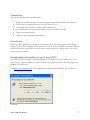
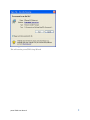
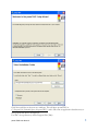
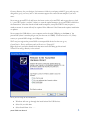
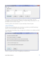
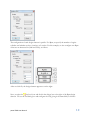
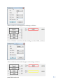
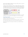
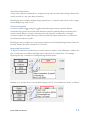
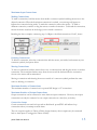
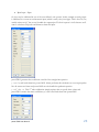
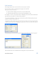
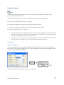
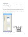
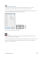
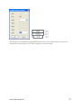
EMBEDDED SPACES INC. (ESI) Technical Documentation ESI powerTWO User Manual V1.5 2011/07/12 powerTWO User Manual 1 Table of Contents Terminology........................................................................................................................................................ 1 Introduction ........................................................................................................................................................ 1 Downloading and installing a copy of powerTWO ...................................................................................... 1 Software Updates ............................................................................................................................................... 5 When An Update Is Available ..................................................................................................................... 5 A powerTWO Update ............................................................................................................................. 5 A powerONE Update .............................................................................................................................. 6 Identifying powerONE controllers ................................................................................................................. 7 By Serial Number .......................................................................................................................................... 7 By Firmware Version .................................................................................................................................... 7 powerONE controller status ............................................................................................................................ 7 Creating Designs ................................................................................................................................................ 9 Creating Design Objects .............................................................................................................................. 9 Quick Example #1 – Rpm and 2 Leds .................................................................................................. 9 Design Element Changes ...........................................................................................................................12 Connections .................................................................................................................................................13 Types of Connections ............................................................................................................................13 Connection Attributes............................................................................................................................13 Connector Symbols ................................................................................................................................14 Inspecting Connections .........................................................................................................................14 Maximum Input Connections ...............................................................................................................15 Making Connections...............................................................................................................................15 Deleting Connections.............................................................................................................................15 Moving Connections ..............................................................................................................................15 Maximum Number of Connections .....................................................................................................15 Maximum Number of Output Connections.......................................................................................15 Connection Loops ..................................................................................................................................15 Maximum Number of Input Connections ..........................................................................................16 Steps ..............................................................................................................................................................16 Step Value Sorting ..................................................................................................................................17 powerTWO User Manual i Adding A Step Value ..............................................................................................................................17 Removing A Step Value .........................................................................................................................17 Design Element Errors...............................................................................................................................17 Design Element Warnings .........................................................................................................................17 Selecting and Moving Design Elements ..................................................................................................17 Selecting a Single Design Element .......................................................................................................17 Quick Moving a Single Design Element .............................................................................................17 Selecting Multiple Design Elements ....................................................................................................18 Moving Design Elements with Mouse ................................................................................................18 Moving Design Elements with Cursor Keys ......................................................................................18 Inspecting Design Elements .................................................................................................................18 Modifying Design Elements..................................................................................................................18 Aligning Design Elements .....................................................................................................................18 Distributing Design Elements ..............................................................................................................19 Managing Multiple Designs .......................................................................................................................19 Tool Icons ....................................................................................................................................................19 Downloading a Design ...............................................................................................................................19 Monitoring a Design ...................................................................................................................................20 Recording Telemetry from a Design ........................................................................................................20 Recorded Data File Names ...................................................................................................................21 Logging Designs ..........................................................................................................................................21 Logging Data File Names ......................................................................................................................21 Units Management ...........................................................................................................................................22 Default Units ................................................................................................................................................22 User-defined Units ......................................................................................................................................22 Calibration ....................................................................................................................................................22 Unit Conversions.........................................................................................................................................24 Units checking .............................................................................................................................................25 Design Elements ..............................................................................................................................................26 User .....................................................................................................................................................26 User Inputs ..............................................................................................................................................26 powerTWO User Manual ii User Outputs ...........................................................................................................................................30 Can OBD-II .......................................................................................................................................34 Can OBD-II Pids ....................................................................................................................................35 Rpm .....................................................................................................................................................36 Led .......................................................................................................................................................37 Switch ..................................................................................................................................................38 Input Decoder ...................................................................................................................................38 Logical Operators ........................................................................................................................................40 Logical Operator Example ....................................................................................................................40 And .................................................................................................................................................40 Or ....................................................................................................................................................41 Xor ..................................................................................................................................................41 Timer or Delay ..................................................................................................................................42 Delay .........................................................................................................................................................42 Oneshot ....................................................................................................................................................42 Retriggerable ............................................................................................................................................42 MinMax...............................................................................................................................................43 Count ..................................................................................................................................................43 Rslatch .................................................................................................................................................44 Compare .............................................................................................................................................45 Differentiator ......................................................................................................................................46 powerTWO User Manual iii Integrator .............................................................................................................................................47 LogActive ...........................................................................................................................................48 Notes ...................................................................................................................................................48 Ambient Light....................................................................................................................................49 Ambient Temperature ......................................................................................................................50 Vbatt....................................................................................................................................................50 Main Menu Options ........................................................................................................................................52 File Menu ......................................................................................................................................................52 File->New ................................................................................................................................................52 File->Open ..............................................................................................................................................52 File->Save.....................................................................................................................................................52 File->Save As ..........................................................................................................................................52 File->Save All ..........................................................................................................................................52 File->Close ..............................................................................................................................................52 File->Close All ........................................................................................................................................52 File->Revert.............................................................................................................................................52 File->Recent ............................................................................................................................................52 File->Print ...............................................................................................................................................52 File->Print Preview ................................................................................................................................52 Edit Menu .....................................................................................................................................................53 Edit->Undo .............................................................................................................................................53 Edit->Redo ..............................................................................................................................................53 Edit->Select All.......................................................................................................................................53 Edit->Invert Selection ...........................................................................................................................53 View Menu ...................................................................................................................................................53 View->Snap .............................................................................................................................................53 View->25%, 50%, 75%, 100%, 150% and 200% ..............................................................................53 powerTWO User Manual iv View->Zoom In (F2) .............................................................................................................................53 View->Zoom Out (F3) ..........................................................................................................................53 Tools Menu ..................................................................................................................................................53 Tools->Options ......................................................................................................................................53 Tools->Advanced ...................................................................................................................................54 Actions ..........................................................................................................................................................55 Actions->Download ..............................................................................................................................55 Actions ->Monitor .................................................................................................................................55 Actions ->Record ...................................................................................................................................55 Actions ->Logging..................................................................................................................................55 Actions ->Real-time Clock ....................................................................................................................56 Actions ->Wifi ........................................................................................................................................56 Actions ->User Units .............................................................................................................................56 Actions ->User Conversions ................................................................................................................56 Help ...............................................................................................................................................................56 Help->Check for Updates .....................................................................................................................56 Help->About ...........................................................................................................................................56 Download .....................................................................................................................................................56 Record ...........................................................................................................................................................56 Monitor .........................................................................................................................................................56 OEMs and VARs ........................................................................................................................................56 Trouble Shooting.........................................................................................................................................57 powerTWO Log Files ............................................................................................................................57 powerONE Diagnostics ........................................................................................................................57 powerTWO User Manual v powerTWO User Manual 1 Terminology This manual uses the following terminology: design: a powerONE design that contains design elements such as Rpm, Leds and more design element: a specific element in a design, such as a Led powerONE: a powerONE controller (physical hardware) powerONE firmware: the software running on the powerONE controller VAR: a value added reseller OEM: an original equipment manufacturer Introduction The powerTWO application is a graphical user interface (GUI) that manages powerONE designs. Designs can be created, modified, and downloaded to one or more powerONE controllers. Designs can be monitored by powerTWO, showing current values interactively. Design values can also be recorded for later analysis. Downloading and installing a copy of powerTWO powerTWO has been qualified to run under Windows XP, Windows Vista and Windows 7. If you don‟t have any of those available, it‟s time to acquire one or pack up the unit. The following are the Windows XP interactions. Visit http://www.emspace.com, select QuickStart and download powerTWO. You will then see: Click Run. powerTWO User Manual 1 Click Run again. This will start the powerTWO Setup Wizard. powerTWO User Manual 2 Click Next. Click Next and Next at the next two windows. This will place powerTWO in C:\Program Files\Embedded Spaces Inc\powerTWO\, and it will create an application data directory to store powerONE device descriptions. For Win7 the top directory will be Program Files (X86). powerTWO User Manual 3 Create a directory for your designs, for instance a folder in your laptop called P2_pox, and copy any design files (.pox) you have, into it. Ask customer support for some relevant samples if you have none. Now start up powerTWO. It will locate the latest version of powerTWO and suggest that you load it. “ powerTWO update is available”. Select it to start the update manager, close powerTWO and follow the instructions. After the download and install completes, start powerTWO. It may request a windows restart. A restart will only be required if the Microsoft .Net Framework requires installation or updates. Now connect the USB cable to your computer and to the mini USB plug on the front of the powerONE (there is another plug at rear, but that one is ODBII). You don‟t need a +12 (Vbatt) source yet. powerONE is happy on USB power. Win7 may just register the powerONE as an unspecified device. In that case go to; Control Panel > Devices and Printers and you‟ll see it as “Unspecified”. Right click on it and select Install from that menu and it will bring up this wizard. XP and Vista will go directly to the wizard. Now, the last steps in the installation: Windows will now go through the install wizard for USB devices Select No, not this time Select Install from a list …… powerTWO User Manual 4 Select Search from the best driver in these locations and browse to C:\program files\Embedded Spaces Inc\powerTWO. On Windows 7, use C:\Program Files (x86)\... instead It will install the powerONE as a com port The next time you attempt to use the powerONE, powerTWO will tell you if it needs to download any information for the powerONE device to your host PC Select the Tools> Options pulldown o Select the Design tab and choose degrees F or C. o Select the General tab and Re-open last files at Startup; this option ensures that any designs you last had open are opened again whenever powerTWO starts. o Change anything else to taste but leave Search and Events alone unless directed there by Customer Service. Software Updates By default, powerTWO will periodically check for software updates (both for powerTWO and for powerONE). Update checking takes only a few seconds. We strongly encourage users to enable software update checking and to apply any updates that are available. Software update checking requires an active internet connection. If your firewall notifies you that an application ESIpowerTWO.exe is attempting to access the internet, it is the powerTWO application and you should let it proceed. Similarly, if your firewall notifies you that an application ESIUpdateManager.exe is attempting to access the internet, it is the Update Manager that wants to download new updates, and you should let it proceed. When An Update Is Available A powerTWO Update Normally, powerTWO is configured to check for powerTWO updates when it starts. If an update is available, a notification appears in the task bar area, as follows: You can then click the notification to run the Update Manager which will download and install the newer powerTWO. If your current version of powerTWO is 1.2.79 and a newer version 1.2.81 is available, the Update Manager would appear as follows: powerTWO User Manual 5 Click Update to download and start installing the newer version of powerTWO. Note that powerTWO cannot be installed while it is running, so the Update Manager will prompt you to close powerTWO if you haven‟t done so already. Alternately, updates can be checked for at any time with Help->Check for Updates. A powerONE Update Notification for powerONE updates only occurs when you perform a powerONE related target operation, such as downloading or monitoring a design. For example, when downloading a design, you might receive notification of an available powerONE update, as follows: Click Ok to install the new version to all applicable powerONE devices. powerTWO User Manual 6 You have the option to ignore the powerONE update for a day, or forever. If you have chosen to ignore the powerONE update, you can be reminded again by unchecking the applicable options in Tools->Options->Updates. Once you click OK, you‟ll be presented with a form that lists each attached powerONE device. Press Flash to update the firmware. Identifying powerONE controllers By Serial Number Every powerONE has a unique serial number. A unique serial number is required for all USB connected device to allow the Operating System to distinguish between multiple devices. By Firmware Version Every powerONE has a firmware version. A version is indicated by V with a version number and the date and time that version was built; a unique serial number is included, as follows: powerONE V1.1.11 – 2011/07/05 13:06:20; sn 81152724 This identifies the powerONE as version 1.1.11, built at 2011/07/05 13:06:20. The powerONE has a unique serial number of 81152724. powerONE controller status All powerONE target operations provide the status of each connected powerONE with respect to the operation being performed. The target status appears to the left of the controller description and may be one of: Assign Serial Number: the powerONE does not have a valid serial number and a valid serial number must be assigned to it. Incompatible: the powerONE is incompatible and needs newer firmware Needs application: the powerONE does not have valid firmware Needs download: the powerONE needs a download of the current design or a download of newer firmware Ready: the powerONE is ready to perform the requested operation Unrecognized: the powerONE firmware is not recognized Up to date: the powerONE is up to date and the requested operation does not need to be performed on it Will Downgrade: the powerONE has more up to date firmware than the firmware that is about to be programmed into it powerTWO User Manual 7 powerTWO User Manual 8 Creating Designs Create a new, empty, design with File->New. Save the new design with File->Save to a folder of your choice. Creating Design Objects On the main tool bar, you will see the following tool icons: These same icons are also accessible on a popup menu if you right-click in the design. When you click on any of the icons above and move the mouse into the design, your cursor will be the tool icon that you have chosen. To get back to a normal cursor, either select the pointer icon on the tool bar or press the ESC key. To create a new design object, click on the spot in the design where you want to place the design element. A dialog box will appear so you can configure the design object. Designs can contain only a certain number of design elements, depending on the type of the design element. For example, a design can contain only 1 Rpm design element, but up to 12 Led design elements. After a design element is created, the cursor will return to a pointer if no more design elements of that type can be created. Quick Example #1 – Rpm and 2 Leds Topics Covered Creating and positioning design elements Making connections For the purposes of this example, we are going to create a Rpm design element with 2 Rpm values, 1 yellow Led that will light when the current Rpm value is at least 1000 and 1 red Led that will blink at a period of 250 ms when the current Rpm value is at least 5500. For the yellow Led, we‟ll choose Led0 which is the left-most Led on the front of the powerONE. For the red Led, we‟ll choose Led 5, which is in the middle on the front of the powerONE. Last, but not least, we will connect the Rpm values to their respective Leds. Please note that, for illustrative purposes, this example omits many details. To create the Rpm design element, select the the following dialog box: powerTWO User Manual Rpm tool icon and click in the design. You will see 9 The configuration of each design element is specific. For Rpm, we specify the number of engine cylinders and whether we have 4 strokes or 2 strokes. For this example, we also configure two Rpm values we are interested in (1000 and 5500), as follows: After we click Ok, the design element appears as on the right.: Next, we select the Led tool icon and click in the design, but to the right of the Rpm design element. We see the Led dialog box and configure the Led, giving it the name Shift, as follows: powerTWO User Manual 10 After we click Ok, the Led appears in the design, as follows: Now, we‟ll add the second Led, this time clicking just under LED5, as follows: After we click Ok, the second Led appears in the design, as follows: powerTWO User Manual 11 Finally, we connect the Rpm Value 1000 to the Activate input of LED0. Likewise, we connect the Rpm Value 5500 to the Blink input of LED5. Connections are made by holding the mouse down over a connector (either a square or diamond) and dragging the mouse to another connector. To connect LED0, hold the mouse down over the square connector of Rpm Value 1000 and drag the mouse to the l connector of LED0. Similarly, to connect LED5, hold the mouse down over the square connector of Rpm Value 5500 and drag the mouse to the b connector of LED5. Once we have done this, we see the connections, as follows: Congratulations! We now have a, albeit, simple design that can be downloaded to the powerONE unit and run (as soon as we physically connect the Rpm input on the back of the powerONE). Design Element Changes Changes to design elements are categorized as major or minor. Major changes change the functionality of a design, while minor changes do not. Major design changes that have not been saved are indicated by an asterisk (*) next to the design name. Minor changes to designs that have not been saved are indicated by a plus sign (+). Major design changes require that the design be downloaded to the powerONE; minor design changes do not. powerTWO User Manual 12 Connections Types of Connections There are two types of connections to any design element: an input connection and an output connection. An input can be connected to an output, and vice versa. In addition, a connection has attributes. Connections can only be made if each connector has the same attribute. Connection Attributes Logical Connections The most common connection attribute is a logical connection which is true or false. For design elements that have multiple logical input connections, extra indicators are used to show the functionality of the input connection. Recalling the above example, a Led has a normal logical input connection, indicated by l, that causes the Led to turn on or off, but it also has another logical input connection, indicated by b, that causes it to blink instead. The following is the complete list of logical connection attributes: b: blink c: clear d: disable e: enable l: logical o: override p: preset s: stepvalue v: value +: count up -: count down >: compare greater than Value Connections A value connection, indicated by v, outputs a value that can be received by a value input connection. Recalling the above example, the Rpm design element has a v connection that can be used to output the actual Rpm value (as opposed to a step). powerTWO User Manual 13 Step Value Connections A step value connection, indicated by s, outputs the step value associated with a design element that can be received by a step value input connection. Recalling the above example, the Rpm design element has a s connection that can be used to output the actual Rpm step value (1 or 2). Connector Symbols Connector symbols are rectangles or diamonds. Rectangle connector symbols indicate connections that cannot be inverted while diamond connector symbols indicate connections that can be inverted. Where an output connection cannot be inverted, as indicated by a rectangle connector symbol, the output value may still be inverted if the input connection it is connected to has a diamond connector symbol. Recalling the above example, the l step output connections from the Rpm design element cannot be inverted, whereas the input connections to a Led can. Inspecting Connections To inspect a connection, rest the mouse over the connector symbol. Text will display to indicate the type of connection, its attributes and what other connections it is connected to. For example, inspecting the step 2 connection of the Rpm design element shows: Similarly, if we rest the mouse over the blink connector of Led 5, its attributes are shown, as follows: powerTWO User Manual 14 Maximum Input Connections Making Connections To make a connection, hold the mouse down inside a connector symbol and drag the mouse to the desired connection. When the destination connection is reached, a text message will appear to indicate the connection being made. To make the connection, release the mouse. To make a different connection, continue to drag the mouse to another connection. To discard the connection, release the mouse anywhere in the design, just not inside a connector. Recalling the above example, connecting step 2 of Rpm to the blink connection of Led 5, shows: Deleting Connections To delete a connection, select the connection line with the mouse, not inside, but between any two connector symbols, then press delete. Moving Connections To move a connection, hold the mouse down over a connection line and drag the mouse to another connection. The connection furthest away from the mouse will be broken while the connection closest to the mouse will be maintained. Moving a connection and releasing the mouse outside of a connector symbol performs the same action as deleting a connection. Maximum Number of Connections The maximum number of connections in a powerONE design is 127 connections. Maximum Number of Output Connections Output connections can be connected to more than one input connection. However, most input connections can only be connected to one output connection at a time (but, see below). Connection Loops Certain connections can result in loops and are disallowed. powerTWO will indicate loop connections when you attempt to make them. The sole exception applies to Timer or Delay design elements, whose outputs may be connected back to their inputs to retrigger the Timer or Delay. powerTWO User Manual 15 Maximum Number of Input Connections To avoid ambiguity, the maximum number of inputs connections for all design elements (except for input connections to logical operators) is 1. For example, a value input connection cannot be connected to more than one value output connection. Similarly, a step value input connection cannot be connected to more than one step value output connection. Use logical operators to connect more than 1 logical output connection to a logical input connection. Use the Or operator if any one logical output connection should activate a logical input connection. Use the And operator if all logical output connections should activate a logical input connection. Logical operators can have up to 8 logical input connections. Multiple logical operators can be connected together to process more than 8 logical input connections, if required. In the following example, the red Led 11 is turned on whenever the Rpm input value is 6500 or higher, or when the water temperature (ECT) from Can is 95 ° Celsius or higher: Steps Any design element that has values can have associated steps. Not unlike steps on a ladder, if you are on step 3 of a ladder, you are also above steps 1 and 2. Recalling Example #1 above, the Rpm design element was configured with 2 Leds, as follows: powerTWO User Manual 16 In this example, the Rpm design element has 2 steps with values 1000 and 5500. Any time the Rpm value is less than 1000, neither step 1 nor step 2 is true (or active). When the Rpm value is, for example, 2350, step 1 is true, but step 2 is not. When the Rpm value is 5500 or higher, both step 1 and step 2 are true. Steps are a fundamental concept in powerONE designs. They are used in Rpm inputs, Can inputs, User inputs (Analog, Frequency and Interval), Count and Input Decoder design elements. Step Value Sorting Step values are sorted in ascending order automatically. When a step value is changed, it is sorted in ascending order and its connections are moved. Adding A Step Value To add a new step value, double click the design element, increase the number of steps and enter a new step value. The step values will be sorted automatically and their associated connections will be moved. Removing A Step Value To remove a step value, double click the design element and decrease the number of steps. The highest step values will be removed along with their associated connections. Design Element Errors Errors in design element are flagged with an error flag at the top of the design element. Hold the mouse over the design element to show the errors. All errors in design elements must be resolved before a design can be downloaded to powerONE. Design elements that have errors are also displayed in red. Design Element Warnings Warnings in design elements are flagged with a warning flag at the top of design elements. Warnings need not be resolved before a design can be downloaded to powerONE, but they indicate that the functionality of a design may be different than expected. Selecting and Moving Design Elements Selecting a Single Design Element To select a single design element, click the design element. Quick Moving a Single Design Element To quick move a single design element, hold the mouse down on the design element and drag it to the desired location. powerTWO User Manual 17 Selecting Multiple Design Elements Using a Selection Rectangle Hold the mouse down outside of any design element and drag the mouse to make a selection rectangle that will select all design elements that it encompasses. Release the mouse to select the design elements. Once design elements are selected, Ctl-Click can be used to select or deselect additional design elements. Using Ctl-Click Ctl-Click a design element. If the design element is not selected, it is selected. If the design element is selected, it is deselected. Using Shift-Click Shift-Click a design element to select all design elements between the first selected design element and the mouse position. Moving Design Elements with Mouse Once multiple design elements are selected, hold the mouse down over any selected design element and drag to move all selected design elements. Moving Design Elements with Cursor Keys Use the left, right, up or down cursor keys to move selected design elements in the indicated direction. Use Ctl with left, right, up or down to move the selected design elements 10 times as far as with just the cursor keys alone. Use Shift with left, right, up or down to move the selected design elements 25 times as far as with just the cursor keys alone. Inspecting Design Elements To inspect a design element, rest the mouse over the design element. Text that describes the specifics of the design element will appear. When more than one design element is selected, no text will appear. Modifying Design Elements To modify a design element, double the design element. A dialog box with the specifics of the design element will appear, allowing modifications to be made. Aligning Design Elements Whenever two or more design elements are selected, their left sides or their tops may be aligned. With the design elements selected, right-click the mouse. Choose Align->Left or Align->Tops. powerTWO User Manual 18 Distributing Design Elements Whenever three or more design elements are selected, they may be distributed with equal spacing, horizontally or vertically. With the design elements selected, right-click the mouse. Choose Distribute->Vertically or Distribute->Horizontally. Managing Multiple Designs Multiple designs appear as multiple tabs. To switch to a different design, click its associated tab. Tool Icons The following Tool Icons are available on the main tool bar. These same Tool Icons are also available by right-clicking in a design. To create a new design element, selects its icon from the tool bar and drop it into your design with a mouse click. Normal cursor (or press ESC) Led User input or output Switch Can (OBD-II) input Input Decoder Logical Or Logical Xor Count Events Rslatch Timer or Delay Compare Integrator LogActive control Vbatt Ambient Temperature Design Notes Design degree units; c is Celsius, f is Fahrenheit Rpm input Logical And MinMax Differentiator Ambient Light Warnings Downloading a Design Once a design is created and contains no errors, it can be downloaded to a powerONE with the Download command available on the tool bar. After the design is downloaded, the powerONE will restart and start running the downloaded design. Designs are downloaded over USB. Designs can be downloaded to more than one powerONE if multiple powerONEs are connected. powerTWO User Manual 19 Monitoring a Design Once a design has been downloaded, the actual values and connection states of the design running on the powerONE may be monitored with the Monitor command available on the tool bar. To stop monitoring, use the Stop Monitor command on the tool bar (only visible when monitoring). Major design changes cannot be made while monitoring is in progress. Minor changes, such as moving design elements, can be made. Monitoring data is sent to the host PC via the USB connection on the front of the powerONE. The following design shows our now familiar example when the current Rpm value is 1302: Note that Rpm step 1 is highlighted because the Rpm value is 1000 or higher and that the connection to Led 0 is blue because it is active. When the Rpm value reaches 6054, the design will be shown as: Note that both Rpm steps are now highlighted, that both connections are now blue and that Led 5 is shown in red when it was captured (though it will be blinking). Recording Telemetry from a Design Once a design has been downloaded, the actual data values may be recorded from the powerONEwith the Record command available on the tool bar. Designs cannot be modified while recording is in progress. Recording data is sent to the host PC via the USB connection on the front of the powerONE. To record, choose the sample rate and how long to record for. powerTWO User Manual 20 Recording also allows an option to add a timestamp to the text file name. Use this option if you want to record multiple runs of the same powerONE without overwriting previous recorded data. To stop recording before all requested samples have been recorded, click Stop Record available on the tool bar (only visible when recording). Recorded Data File Names Recorded data is available in a text file in the folder that you chose at the beginning of recording. The text file can be imported into a Spreadsheet application. The name of the text file is powerONE-Record-<timestamp>-<serialnumber>.txt if the timestamp option was chosen, powerONE-Record-<serialnumber>.txt if the timestamp option was not chosen. Logging Designs As opposed to recording data, the powerONE can log design data in non-volatile onboard memory. The onboard memory, however, is limited (depending on the powerONE hardware version), as compared to recording data. Data is logged only when the design contains a LogActive design element and then only if the input to the LogActive design element is true. This allows conditions to be defined under which data is logged. Logging data is a good choice when it is not possible to locate the host PC inside the vehicle while the vehicle is in operation. To log designs, first download your design to the powerONE. Then, configure the data to log using Actions->Logging->Configure. After operating the vehicle, connect a host PC to the USB connection on the front of the powerONE and select Actions ->Logging->Get to get the logging data. Logging data is configured by specifying the interval at which the data is to be logged and by the amount the data has to change before it is logged. Once the onboard logging memory fills, the oldest logging values are replaced by newer logging values. Logging Data File Names Logged data is available in a text file in the folder that you choose when logging data is retrieved. The text file can be imported into a Spreadsheet application. The name of the text file is powerONE-Log-<serialnumber>.txt. powerTWO User Manual 21 Units Management The User input types [Analog, Frequency and Interval] each carry engineering-unit definitions which are properties of the data coming in that particular UserIO. The units are passed along with the data and are considered by powerONE every time it handles an input datum. Default Units The default units are: Volts: for an analog input Hz: (hertz) for a frequency input and ms: (milliseconds) for in interval input Rpm User-defined Units We often wish to use other units to express a control or monitoring design. The default units (Volts, Hz, ms, Rpm) are pre-populated, but we add our own units from the Action Menu item “User Units”. The precision specified defines the displayed precision when a value is monitored. This menu is also accessible from the User-input specification pulldown for units, item .manage. The latch is a special case: If its value input is connected to another object it inherits the units with the value. If its value comes only from a preset, then it must select the units to accompany the value Calibration User Inputs may be defined in their native units: Analog Input – Volts Frequency Input – Hz Interval Input – ms powerTWO User Manual 22 Rpm Input – Rpm Or, they may be calibrated in one of the user-defined unit systems. In this example an analog input is calibrated to convert an accelerometer input (which is really volts) into fpsps. This is feet/sec/sec, usually written as fps2, but we can‟t handle the superscripts. We don‟t express it in Gs because we‟ll want to calculate real speeds and distances from this input. powerTWO generates the coefficients a and b of the straight-line equation y = ax + b; and loads them into powerONE. It then performs this calculation at every input update. Not all sensors are linear and powerONE can also handle the quadratic equation y = ax2 + bx + c. This 2nd order calibration simply requires that we specify three values and powerTWO extracts the three coefficients; a, b and c and loads them into powerONE. powerTWO User Manual 23 Unit Conversions Some design elements must convert values from one unit system to another Unit conversions are linear, so the designer must supply a scale and offset. There are two forms of conversion: Scale then Offset: multiply the user unit by a scale, then add an offset Offset then Scale: add an offset to the user unit, then multiply by a scale For example, to convert a user unit from Celsius to Fahrenheit, the conversion form would be Scale then offset, the scale would be 9/5 and the offset would be 32. To convert from Fahrenheit to Celsius, the conversion form would be Offset then Scale, the scale would be 5/9 and the offset would be -32. A Comparator would normally change units only when its two inputs are of the same type but from a different system. In this case it‟s comparing two speeds, but one is feet/sec and the other miles/hr. We had already given the rule for this conversion using the Action Menu item “User Conversions”. The conversion menu is also accessible from the .manage item on any conversion select. powerTWO User Manual 24 Integrators and differentiators normally change units. An integrator performs a time integral and is used to change things like acceleration to velocity, fuelflow to mass, and current to charge, etc. So anything that is ft/sec2 to ft/sec, lb/sec to lbs or amperes to ampere-secs (coulombs). A differentiator measures the rate of change of a value and is the complement to an integrator. If we have a velocity input, a differentiator will tell us the acceleration. For a changing weight input in lbs it will give use change rate in lb/sec. Units checking powerTWO validates the unit consistency as a value is passed from one object to the next. Normally the units are just passed along also, but when a value is passed to an object that has its own unit definition, they must match and powerTWO will show a diagnostic if they do not. powerTWO User Manual 25 Design Elements User A User design element corresponds to one of the 8 UserIO connections on the back of the powerONE, numbered from 0 to 7. All user design-elements can be given a user-defined name to indicate their purpose. UserIOs can be configured as inputs or as outputs. User inputs can further be assigned as Analog, Freq, Interval or Sense. User outputs can further be assigned as Control, Pwm Entry or Pwm Table. UserIOs are identical with two exceptions: User2 through User7 can sample at 200 Hz when used as Freq inputs and can handle a wide range of input voltages. User0 and User1 can sample at 10,000 Hz when used as Freq inputs, but require a „high‟ input level of at least 11.5Volts. User6 and User7 can modulate at up to 2,000 Hz when used as Pwm outputs, whereas User0 through User5 can modulate at up to 200 Hz when used as Pwm outputs. User Inputs Sense User Inputs A sense user inputs reads a logic input, determines whether the input is high or low and outputs a logical value. The following example shows a sense input which is connected to the ignition circuit of an “always-powered” powerONE. When created, the sense user input appears as on the right. powerTWO User Manual 26 Analog User Inputs Analog user inputs read voltage inputs and convert them to digital values. Voltage inputs may vary from 0 to 17.8V V. Higher voltages are clamped at this level and will not damage a powerONE unless they exceed 50 Volts. Analog user inputs provide the digital value, the associated step value and steps as outputs. See the “Units Management section” for Units selection, definition and calibration. The sensitivity for an analog input is how much the input value must change before a change is recognized. The following example is an analog input calibrated to an ECT(Engine Coolant Temperature) sensor. The sensor has an output voltage of 12.0 at 0 degrees and an output voltage of 3.0 at 250 degrees, with 2 steps (150 and 210), as follows: When created, the analog input appears as on the right. See the “Units Management section” for Units selection and definition and for calibration. powerTWO User Manual 27 Freq User Inputs Freq user inputs measure the frequency of a logic input, i.e. how often the logic input changes. UserIOs 0 & 1 measure frequencies up to 10 kHz and require an input high level of 11.5 Volts or more. UserIOs 2 to 7 measure frequencies up to 200 Hz. Freq user inputs provide the frequency value, the associated step value and steps as output. The following example is a frequency input calibrated to a magnetic sensor on a driveshaft. With a 3.43 differential & 20" tire (5.24 ft. in circumference) 1 shaft rev = 5.24/3.43 = 1.53 ft 88 fps (60mph) = 57.6 Hz We‟ve chosen steps at 176 fps and 220 fps (120 and 150 mph), as follows: When created, the Freq input appears as on the right. See the “Units Management section” for Units selection and definition and for calibration. powerTWO User Manual 28 Interval User Inputs An Interval user input measures the interval, in ms, between changes in the logic input signal. Its actual resolution is 2.5 msec. Whether intervals in logic input signal are to be measured for the logic signal‟s high or low state must be specified. Interval user inputs output the interval value, the associated step value, and steps. The following example is a interval input calibrated to a magnetic sensor on a front wheel. With a 20" tire (5.24 ft circumference) 88 fps(60 mph) = 16.8 Hz We‟ve chosen steps at 176 fps and 220 fps (120 and 150 mph), as follows: When created, the Interval user input appears as on the right: See the “Units Management section” for Units selection and definition and for calibration. powerTWO User Manual 29 User Outputs All user outputs have inputs, override, and disable input connections, which are active high or low. In addition, all user outputs specify whether their output is high or low. When the input connection to a user output becomes true, its output becomes true. When the override connection to a user output becomes true, its output becomes true. An override connection takes precedence over the input connection. When the disable connection to a user output becomes true, its output becomes false. A disable connection takes precedence over the override connection. Control User Outputs Control user outputs provide a logic output high or low. Control user outputs use the input connection that triggers their logic output. The following example creates a Rev Limiter which outputs a logic Low when its input connection is true, as follows: When created, the Control user output appears as on the right: Note that active low signal on the right that indicates that this Control user output is active low. During monitoring, this signal will change between low and high, depending on the state of the Control user output. powerTWO User Manual 30 Pwm Entry Output Pwm Entry user outputs provide pulse-width modulation outputs and are triggered by their input connection. User 0 through User 5 provide a lower speed output rate of up to 200 Hz, while User 6 and 7 provide a high speed output rate of up to 3,000 Hz. Pwm Entry outputs are defined in frequency and duty-cycle by specifying their on-time and offtime. They may run continuously when their input is true or they may optionally be configured for a delay before the output begins and an output duration. If they are given a delay and duration, they may also be given a repeat count; in which case they deliver a pulse-train. All times are in milliseconds. The following example creates a Pwm Entry output: When created, the Pwm Entry output appears as on the right: This would delay issue 5 - 50 Hz chirps, each ½ second long and separated by ½ second. Note that the waveform on the right indicates that this output is a Pwm output. During monitoring, the Pwm waveform will be shown as will the frequency and duty-cycle. An active high or low signal will be shown when the Pwm output is not active. powerTWO User Manual 31 Pwm Table User Output Pwm Table user outputs provide up to 8 different Pwm Entry configurations. Whereas Pwm Entry user outputs are triggered by a logic input, Pwm Table user outputs are triggered by a value or step value input to allow different table entries to be selected. The following example creates a Pwm Table user output with 2 entries which are selected by a step value. The second entry (shown here) will modulate the fan at 1 kHz and a 40% duty-cycle. The following example shows the above Pwm Table user output connected to the step value output connection of an Rpm to select the first Pwm Table entry when the Rpm Value is 1000 or higher and the second Pwm Table Entry when the Rpm Value is 6500 or higher: powerTWO User Manual 32 The more interesting case takes a value input and interpolates between the column values. This provides variable-speed and variable duty-cycle operation with the simplest possible definitions. In this example, a cooling fan is off until the temperature reached 100 degrees. Then from 100 to 200 degrees it advances linearly from 0% to 25% duty-cycle at 2 kHz. And from 200 to 230 degrees it advances from 25% to 100 % duty cycle at 2 kHz. powerTWO User Manual 33 Can OBD-II A Can design elements reads a Can (Controller Area Network) OBD-II PID value from the ECU (Engine Control Unit) and provides the OBD-II value, associated step value and associated steps as outputs. The interval at which the OBD-II value is read and the sensitivity (by how much the OBD-II value must change before a change is recognized) can be specified. When an OBD-II value has temperature units, it is configured according to the temperature units selected. The following example creates a Can design element that reads the VSS (Vehicle Speed): Once created, the Can design element appears as on the right: powerTWO User Manual 34 Can OBD-II Pids The following table lists the OBD-II Pids that have been defined for powerONE. Name LOAD ECT FPR MAP RPM VSS ADV IAT MAF TPS RUNTM FRP BARO LOAD_ABS TP_R AAT O2S Mode 1 1 1 1 1 1 1 1 1 1 1 1 1 1 1 1 1 Pid 4 5 10 11 25 13 14 15 16 17 31 34 51 67 69 70 20 Units % ° kPa kPa Rpm Km/h 1 ° % Sec kPa kPa % % ° V Description Total engine load Engine coolant temperature Fuel pressure (kPa gauge) Intake manifold pressure (kPa absolute) Engine RPM Vehicle speed Timing advance Intake air temperature MAF air flow rate (g/s) Throttle position (%) Runtime since start (seconds) Fuel rail pressure Barometric pressure (kPa absolute) Absolute load value (%) Relative throttle position (%) Ambient air temperature Oxygen Sensor ° relative to #1 cylinder powerTWO User Manual 35 Rpm An Rpm object reads the engine Rpm. Up to 12 Rpm steps may be defined for use in controlling other function. Because the RPM input may originate from an ECU or the ignition system or elsewhere, we must define the number of pulses per revolution (ppr). This definition may be by cylinder and strokes or stroke count, or directly as pulses per revolution. The sensitivity specifies how much the Rpm value must change before that change is recognized. For Rpm to function, the Rpm input on the back of powerONE must be physically connected. Simulate may be enabled to have the powerONE simulate Rpm values for test purposes without having to connect the Rpm input on the back of the powerONE. Simulated Rpm values increment from 0 to 12000. A warning flag appears on the top of the Rpm design element when simulation is enabled. The following example defines Rpm for an 8 cylinder, 4 stroke engines and assigns 3 step values (1000, 3000 and 5500), as follows: When created, the Rpm design element appears as on the right: powerTWO User Manual 36 Led A Led object controls one of the 12 Leds (10 yellow, 2 red) on the front of the powerONE. Leds have two input connections: one to turn the Led on and another to blink the Led at a specified interval. When both inputs are connected, the blink input takes precedence over the Led on input, if both inputs are active at the same time. Leds blink at a 50% duty cycle. Input Active specifies whether the input connection is active when high or low. Blink Active specifies whether the blink connection is active when high or low. The following example creates a Led Warning that blinks the right-most red Led (Led 11) at a period of 250 ms or 4 Hz (125 ms on, 125 ms off), as follows: When created, the Led appears as on the right: powerTWO User Manual 37 Switch A switch provides a logic high or low output that can be connected to other logic inputs. Common uses for switches are to turn on a certain Led or to turn on or off a LogActive design element. The following example creates a Switch Logging which always outputs a logic High, as follows: When created, the Switch appears as on the right: Note that the signal on the right of the switch reflects the configured output state. Input Decoder An Input Decoder decodes up to 3 logic inputs and provides up to 8 steps. The least significant bit (lsb) to an Input Decoder is connected to the top connection, while the most significant bit (msb) is connected to the bottom connection. All input connections to an Input Decoder must be made. The following example creates an Input Decoder Gear with 2 User sense inputs that provides 4 step values, as follows: When created, the Input Decoder appears as on the right: powerTWO User Manual 38 Note that a newly created Input Decoder always shows an error since input connections to it have not been made. Once we connect User6 as the most significant bit (msb) and User0 as the least significant bit, the Input Decoder appears as: powerTWO User Manual 39 Logical Operators Use Logical Operators to combine multiple inputs and determine whether: all inputs are true (And) any input is true (Or) inputs are not the same (Xor) Most design elements do not accept more than one input connection and so depend on Logical Operators to combine multiple inputs into one.. Logical Operators accept up to 8 inputs. To evaluate more than 8 inputs, connect 8 inputs to a Logical Operator, connect its output to another Logical Operator and connect more inputs to the second Logical Operator. Xor Logical Operators evaluate to true when an odd number of inputs are true, false otherwise. Logical Operator Example There are many uses of Logical Operators. Here, we provide just one example. The result of a Logical Operator is High (True) or False (Low) The following example illustrates a Logical Or Operator that outputs a logic True to turn on the red Led 5 if the current Rpm value is 5500 or higher, or if the water temperature is 280 or higher: And A Logical And operator evaluates up to 8 logical inputs and outputs a logic High value if all inputs are true, a logic Low value otherwise. Use Logical And operators to determine if all inputs are true. powerTWO User Manual 40 Or A Logical Or operator evaluates up to 8 logical inputs and outputs a logic High value is any of the inputs are true, a logic Low value otherwise. Xor A Logical Xor operator evaluates up to 8 logical inputs and outputs a logic High value if an odd number of inputs are high, a logic Low value otherwise. powerTWO User Manual 41 Timer or Delay A Timer or Delay design element is configured for a time period and outputs a logic High value upon completion. It has an InActive input which starts the time period and a ClearActive input which stops operation and forces the output to Low. Both these inputs may be configured to be active High or Low. There are three types of timers. Delay A delay timer replicates the waveform seen at its input but delayed for the specified period. Oneshot Each time the input of a oneshot timer changes from Inactive to Active, the timer begins counting down for the specified period. The output goes to High at the end of that period. While the timer is running, any activity on the InActive input is ignored. Retriggerable A retriggerable timer is very similar to a oneshot timer. The exception is that a new transition to active, occurring before the timer expires, renews timing to another full period. Here is an example of a delay timer used to create a 40 Hz oscillator. Notice the output connection to the input. powerTWO User Manual 42 MinMax A MinMax design element measures an input value and determines its minimum or maximum. It also accepts a clear input connection that clears the measured value. It can also output the measured value to another value input connection. The following example creates a MinMax design element to measure the maximum Rpm value, as follows: Once created, the MinMax design element appears as at right: Count A Count design element counts occurrences of multiple events and outputs a step and the associated step value. The input connections to a Count design element are: enable (e): enable or disable the Count clear (c): clear the count value preset (p): preset the count value increment (+): increment the count value decrement (-): decrement the count value powerTWO User Manual 43 The following example creates a Count design element ECounter that counts up to 4 events, as follows: Once created, the Count design element appears as at right: Rslatch An Rslatch design element latches an input value when commanded by the set input. It also accepts a clear input connection to clear the latched value. It can also output its value to another design element. An Rslatch also has a preset value that initializes the latch before an input value is latched. The following creates a rslatch that latches its input value when commanded to by the output of an Or operator, as follows: powerTWO User Manual 44 The units of a latch value are normally inherited from the object connected to the value input. There is a special case in which the latch has no connection at its value input. Then its value comes only from the preset and the designer must select the units to accompany the value. Compare A comparator takes two input values and compares them. It outputs the signed difference (A – B) and a logical output which is true when input A is greater than input B. A comparator can only evaluate inputs which are expressed in the same units. Comparisons of pounds and volts are ridiculous, but we often have compatible values expressed in different unit systems like metric from an OBD system and US/Imperial from a direct gauge input. A comparator can convert any of its input values from one user unit to another. The output of a compare is in the post-conversion units if any conversion took place. An example can be found in the Unit Conversions section. The following compares a left wheel speed sensor and a right wheel speed sensor: Once created, the Compare appears as: This might be useful for a simple traction-assist which applies braking to the more-rapidly spinning wheel. powerTWO User Manual 45 Differentiator A differentiator measures the rate of change of its input value. For example, if we have a velocity input, a differentiator will give us the acceleration. For a changing weight input in lbs it will give us the rate of change in lb/sec. In the scale input you must look after the integration or differentiation constant and any change of time-base. A differentiator always implies a unit conversion. Luckily the usual conversion factor is 1, as in the following example; the result of differentiating a voltage is just volts/sec. More information about conversions can be found in the Unit Conversions section. The following creates a differentiator with an interval of 100 ms. The example input value is in volts and the differentiator converts its input value from volts to volts/sec. Extending the interval beyond the minimum of 2.5 ms has the effect of smoothing (low-pass filtering) the output and with that filtering it also delays the output. Once created, the Differentiator appears as: powerTWO User Manual 46 Integrator An integrator performs a time integral and is used to change things like acceleration to velocity, fuelflow to mass, and current to charge, etc. So anything that is ft/sec2 to ft/sec, lb/sec to lbs or amperes to ampere-secs (coulombs) An integrator always implies a unit conversion. Luckily the usual conversion factor is 1, as in the following example; the result of integrating an acceleration is just a velocity. More information about conversions can be found in the Unit Conversions section Any integrator has a couple of peculiarities: - - Drift. Errors accumulate in the same way that the desired signal does and an integrator will wander away from the “real” output given enough time. The Clear input is used at the start of any integration to establish a valid beginning datum. Clearing the speed output of an integrator at the stat-line is normal. The vehicle is stopped! Wind-up. Sometimes one uses an integrator to accumulate error. A second order control system with an integral term does exactly this and is prone to having the integrated errorterm wind-up to a meaningless or improperly dominant value. The Maximum and Minimum setting let one limit wind-up within a reasonable positive and negative range. The following creates an integrator that integrates its input value over a period of 2.5 ms: Once created, the integrator appears as at right. The integration interval selected is normally the smallest available (2.5 ms) although longer periods might be used for a quiet (non-noisy), slowly-changing input. powerTWO User Manual 47 LogActive The LogActive design element has a single input connection that defines whether or not logging data should be saved onboard the powerONE. As opposed to recording design data on a host PC, the powerONE has a limited amount of onboard space for logging. LogActive can be used to log only when certain conditions are true. The following example creates a LogActive design element, as follows: Once created, the LogActive design element appears as seen at right above: See Actions ->Logging for more information about logging. Notes The Notes design element allows arbitrary text to be added to powerONE designs. To manage large notes, the Notes design element can be reduced in size by dragging the rectangle at its bottom right. The following example creates a Notes design element, as follows: powerTWO User Manual 48 Once created, the Notes design element appears as: Multiple Notes design elements may be present in a design. Notes design elements are outlined in purple to distinguish them from other design elements. Ambient Light The Ambient design element reads the ambient light sensor on the powerONE. It outputs the ambient light value, the associated step value and steps. The following example creates an Ambient design element and assigns 2 steps (200 and 100): Once created, the design element appears as at right: powerTWO User Manual 49 Ambient Temperature The Ambient Temperature design element reads the ambient temperature sensor on the powerONE. It outputs the temperature value, the associated step value and steps. The following example creates an Ambient Temperature design element with no steps so that the temperature can be displayed when the design is monitored: Once created, the design element appears as: Vbatt The Vbatt design element reads the battery voltage on the powerONE. It outputs the battery voltage, its associated step value and steps. The following example creates an Ambient Temperature design element with one step at 11.5 volts steps so that the voltage can be displayed when the design is monitored and so the design can measure a low-voltage condition: powerTWO User Manual 50 This feature is not functional on powerONE before version 5. In earlier versions, Vbatt can be monitored by connecting it to a UserIO configured as an analog input. powerTWO User Manual 51 Main Menu Options File Menu Note that most actions on the File menu stop monitoring if monitoring is in progress. File->New Creates a new design. New designs are named <Untitled nn> where nn is a unique number. Use File->Save to give the new design a name. File->Open Open an existing design.. File->Save Save changes to the current design. File->Save is enabled only when the current design has been modified. File->Save As Save the current design to another file name. File->Save All Save all designs that have been modified. File->Save All is enabled only when at least one open design has been modified. File->Close Close the current design. File->Close All Close all open designs. File->Revert Revert the changes made to the current design. File->Recent Open a recently closed design. See Tools->Options->Menus to configure how many recently closed designs are tracked. File->Print Print the current design. File->Print Preview Show the print preview for the current design. powerTWO User Manual 52 Edit Menu Edit->Undo Undo the last editing action. Edit->Undo is enabled only when the current design has at least one modification. Edit->Redo Redo the last editing action that was undone. Edit->Redo is enabled only when at least one editing action has been undone. Edit->Select All Select all elements of the current design. Edit->Invert Selection Invert the currently selected elements in the current design. View Menu The View menu controls the design magnification and whether or not design elements are snapped into place. View->Snap If snap is enabled, design elements are snapped into place in multiples of 10 display coordinates. View->25%, 50%, 75%, 100%, 150% and 200% Set the magnification to the indicated scale. View->Zoom In (F2) Use F2 to quickly zoom in to the next magnification scale. View->Zoom Out (F3) Use F3 to quickly zoom out to the next magnification scale. Tools Menu Tools->Options The Tools->Options menu allows selection of general powerTWO options. The categories are: General: how powerTWO starts Design: design options Updates: update checking Oem: OEM options Menus: menu control Search: file search options; use only if directed by Embedded Spaces Inc engineering powerTWO User Manual 53 Events: powerTWO event logging; use only if directed by Embedded Spaces Inc engineering Tools->Options->General The General options are: Reopen Designs at Startup: check to automatically open any designs that were previously open Show Tips at Startup: show powerTWO tips when powerTWO starts Tools->Options->Design The Design options are: Temperatures: choose Celsius or Fahrenheit as the temperature units for design elements that are temperature related. The chosen temperature units are reflected on the Degree tool icon on the main tool bar. Note that changing the temperature units does not change any existing design elements. The selected temperature units apply only to design elements that are subsequently created. Tools->Options->Updates The Updates options are: Check for updates: choose between Whenever powerTWO starts, Once a day, Once a week or Never. powerONE update checking: if you have previously ignored a powerONE update, you can unignore it here. Tools->Options->Oem The Oem options are: OEM Key: a key assigned by ESI to an OEM. Enter your assigned key to brand powerTWO for you. Once a valid OEM key is entered, you will have the opportunity to enter a company name as well. The company name will appear when powerTWO starts and in the title bar of windows along with your design. Tools->Options->Menus The Menus options are: Maximum Recent Items: specify the maximum number of items on the File->Recent menu. Tools->Advanced Use Tools->Advanced for advanced operations. powerTWO User Manual 54 Tools->Advanced->Flash->powerONE Use Flash->powerONE to load powerONE firmware to selected powerONE devices. This option is normally reserved for engineering use. The following example shows the flash application form where 3 powerONE devices are connected. One of the powerONE devices has up to date firmware and is therefore not selected for flashing, while the other two devices have older firmware and are therefore selected for flashing. Tools->Advanced->Serial Number->Assign Use Serial Number->Assign to assign a unique serial number to a brand new powerONE device. This option is normally reserved for manufacturing. You cannot assign a new serial number to a powerONE device that already has a serial number. Tools->Advanced->Diagnostics Use Diagnostics to retrieve powerONE target diagnostics data when requested to by ESI support. Actions The Actions menu provides access to standard powerONE target operations such as downloading a design, monitoring a downloaded design, etc. Actions->Download Use Actions->Download to select one or more attached powerONEs to download the current design to. Actions ->Monitor Use Actions->Monitor to select a powerONE for which to monitor the current design. Actions ->Record Record the current design from a selected powerONE. Actions ->Logging Configure logging on a selected powerONE. Actions ->Logging->Configure Configure logging for a selected powerONE. Select the design element values that you wish to log onboard the powerONE. Actions ->Logging->Get Get logging data for a selected powerONE. powerTWO User Manual 55 Actions ->Logging->Clear Clear the logging data for a selected powerONE. Actions ->Real-time Clock The Actions ->Real-time Clock menu is used to set or get the real-time clock on a selected powerONE. Actions ->Real-time Clock->Get Read and display the real-time clock on a selected powerONE. Actions ->Real-time Clock->Set Set the real-time clock on a selected powerONE to the date and time of the host PC. Actions ->Wifi Configure Wifi for a selected powerONE. Actions ->User Units Manage user units for the current design. Actions ->User Conversions Manage user conversion for the current design. Help Help->Check for Updates Select to check for powerONE and powerTWO updates. This operation is not necessary unless you have disabled update checking on the Tools->Options menu. Help->About Select to show powerTWO and Windows version information. Download Download the current design to one or more attached powerONEs. Record Record design data from one attached powerONE. Monitor Monitor design data from one attached powerONE. OEMs and VARs ESI may assign an OEM or VAR an OEM key that may be used to brand the powerTWO GUI under the OEM brand. See Tools->Options->OEM for more information. powerTWO User Manual 56 An OEM key may also be used by powerONE and powerTWO update checking to supply updates only for a particular OEM. Trouble Shooting powerTWO Log Files powerTWO maintains a collection of log files that record its activities. Log files are created in a folder named „powertwo‟ underneath your Document folder. The latest log file is powerTWO.txt. Previous log files are powerTWO-1.txt, powerTWO-2.txt, etc. ESI support may request that you e-mail the contents of powerTWO log files for further analysis. Note that the latest powerTWO log file can only be viewed when powerTWO is not running. powerONE Diagnostics The Tools->Advanced menu contains a Diagnostics option that allows you to retrieve diagnostics data from a powerONE. ESI support may request that you retrieve diagnostics data and forward the result to ESI for further analysis. powerTWO User Manual 57