1
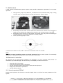
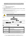
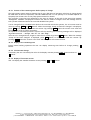
GUIDE D’UTILISATION, INSTALLATION MAINTENANCE ET USAGE HIGH PRESSURE PROPORTIONAL HUMIDIFIER CENTRAL UNITS AND SOLENOIDS CARDS USER, INSTALLATION AND MAINTENANCE GUIDE Ver. 13.01.UK 2 Index 1 PACKAGE CONTENT 3 2 SECURITY MEASURES 3 3 WORKING PRINCIPLE 3 4 MANUFACTURER 4 5 CONFORMITY DECLARATION 5 6 CHARACTERISTICS 6 7 INSTALLATION PRINCIPLES 6 8 INSTALLATION 6 8.1 8.2 8.3 9 10 HYDRAULICS CONNECTIONS ELECTRICAL CONNECTIONS SETTING OF THE BYPASS CONTROL VALVE MAINTENANCE ELECTRONIC CONTROLLER 10.1 NORMAL OPERATION DISPLAY 10.2 ELECTRONIC CONTROLLER BASIC PROGRAMMING 10.2.1 Counter of the remaining time before pump oil change 10.2.2 Display of the remaining time 10.2.3 LCD Contrast change 10.2.4 Display of Firmware version 10.3 ELECTRONIC CONTROLLER ADVANCED PROGRAMMING (ONLY FOR MAINTENANCE/FITTER) 11 ALARM MESSAGES Elsteam S.r.l - via E.fermi, 496 - 21042 Caronno Pertusella (va) - Tel.+39 02 9659890 - Fax +39 02 96457007 E-mail: [email protected]/[email protected] - Web: http://www.elsteam.com p.iva 01463940120 - c.f.05046150156 - trib.di busto a. 16415-c.c.i.a.a. varese 174164 - cap.soc.i.v. euro 10400,00 7 7 8 9 9 9 10 11 11 11 11 12 14 3 Please before using your equipment read this guide carefully, by noting all the precautions and safety instructions reported in it. Keep your equipment in good operative conditions. Familiarize with the working and security instructions related to the operation of your apparatus before trying to make it function. Keep this guide and any other booklet provided with your apparatus to be able to refer to them later. 1 Package content The High Pressure Humidifier package is composed of: The high pressure humidifier central unit This user guide The high pressure pump user manual The inverter user manual A yellow cap for the pump oil to replace the red one (to be used only for transport) 2 Security measures People who are not familiar with this type of apparatus or which did not read attentively this guide do not have to be authorized to use the humidifier. The humidifier is designed to be used on alternative 220Vac 50/60 Hz only. Do not try to connect it to a different type of supply. Check that the sector supply voltage corresponds to that of the apparatus. Your humidifier must always be switched-off before any maintenance operations. All operations of maintenance and repairs must be carried out by the manufacturer, his technical service or any other qualified personnel to avoid any problem. Do not cover any opening of the humidifier and do not insert objects in the openings 3 Working principle The high pressure humidifier performs an adiabatic humidification by atomization of softened water or standard water at high pressure. The system is composed of a central unit, comprising a high-pressure pump with associated control system of the pressure in the network, a card for proportional control of the distribution network and by a series of atomizing nozzles arranged in the environment to be humidified or inside the AHU. The basic system includes a “Solenoid Card” used to control solenoids installed on the distribution network to have proportional opening of nozzles based on the control system request. The system can include a (optional) “Zone Card” used to control different areas with ON/OFF control system using a single central unit. Elsteam S.r.l - via E.fermi, 496 - 21042 Caronno Pertusella (va) - Tel.+39 02 9659890 - Fax +39 02 96457007 E-mail: [email protected]/[email protected] - Web: http://www.elsteam.com p.iva 01463940120 - c.f.05046150156 - trib.di busto a. 16415-c.c.i.a.a. varese 174164 - cap.soc.i.v. euro 10400,00 4 4 Manufacturer Manufacturer Elsteam S.r.l. Sede legale – amministrativa Via ENRICO FERMI 496, 21042 CARONNO PERTUSELLA (VA) - ITALY Contatti Tel.: (0039) 029659890 Fax: (0039) 0296457007 Email: [email protected] Web: www.elsteam.com Elsteam S.r.l - via E.fermi, 496 - 21042 Caronno Pertusella (va) - Tel.+39 02 9659890 - Fax +39 02 96457007 E-mail: [email protected]/[email protected] - Web: http://www.elsteam.com p.iva 01463940120 - c.f.05046150156 - trib.di busto a. 16415-c.c.i.a.a. varese 174164 - cap.soc.i.v. euro 10400,00 5 5 Conformity declaration IL COSTRUTTORE ELSTEAM S.r.l. Azienda Via Enrico Fermi, 496 210142 VA Indirizzo Cap Provincia Caronno Pertusella Italy Città Stato DICHIARA CHE LA MACCHINA High Pressure Proportional Humidifier HPN Descrizione Modello hpn 2008 Serie/Matricola Anno costr. High Pressure Proportional Humidifier Denominazione commerciale Room and AHU Humidifying Uso previsto E’ conforme alle direttive comunitarie 2006/95/CEE “Direttiva Bassa Tensione” del Consiglio 27 Dicembre 2006 89/336/CEE “Compatibilità Elettromagnetica EMC” modificata da: - Direttiva 91/263/CEE del Consiglio del 29 aprile 1991 - Direttiva 92/31/CEE del Consiglio del 28 aprile 1992 - Direttiva 93/68/CEE del Consiglio del 22 luglio 1993 - Direttiva 04/108/CEE del Consiglio del 15 dicembre 2004 Claudio Cattaneo Dirigente Responsabile Funzione ELSTEAM S.r.l.- Via E. Fermi 496 – 21042 – Caronno Pertusella (VA) - ITALY Società 2008 Anno Elsteam S.r.l - via E.fermi, 496 - 21042 Caronno Pertusella (va) - Tel.+39 02 9659890 - Fax +39 02 96457007 E-mail: [email protected]/[email protected] - Web: http://www.elsteam.com p.iva 01463940120 - c.f.05046150156 - trib.di busto a. 16415-c.c.i.a.a. varese 174164 - cap.soc.i.v. euro 10400,00 6 6 Characteristics Technical Data HPN2 HPN4 HPN8 HPNDEMI3 Output Pressure 80 bar Min.Input Pressure 1 bar HPNDEMI5 HPNDEMI7 Nozzles Output Capacity Max. Capacity [l/h] 120 240 480 150 300 420 Max. Nozzles 11 24 47 16 26 37 Electrical Connection Power [kW] 0.6 1.1 2.2 1.0 1.5 2.2 Current [A] 4 6 10 5 7 10 Voltage 220V, 50/60 Hz, Single Phase Mechanical Characteristics Dimensions (LxHxP) 560mmx430mmx330mm Width (kg) 7 Installation Principles The figure below shows the basic working principle of the proportional humidifier. The output signal of the humidistat (0-10V) controls the solenoids controlled card (for proportional working mode) as well as the activation (threshold set at 1V) of the high pressure system. 8 Installation The cabinet of the humidification system must be installed in a ventilated and protected place. It must be placed on a flat and stable surface. For a correct use and operation, as well as for an easy maintenance, leave enough free space around the machine. To enable the correct ventilation of the unit is necessary to ensure a free space of at least 20 cm in the vicinity of the perforated panel for ventilation, which is located on the right wall of the machine. Do not place the machine in dangerous and/or explosive/inflammable places. Elsteam S.r.l - via E.fermi, 496 - 21042 Caronno Pertusella (va) - Tel.+39 02 9659890 - Fax +39 02 96457007 E-mail: [email protected]/[email protected] - Web: http://www.elsteam.com p.iva 01463940120 - c.f.05046150156 - trib.di busto a. 16415-c.c.i.a.a. varese 174164 - cap.soc.i.v. euro 10400,00 7 After installation the red cap of the oil tank, used for the transport, must be replaced by the yellow one, used for normal working operation, provided with the system. The access internal parts of the cabinet remove screws that secure the top and side panels. During the first installation and all the operations of maintenance please take care of the temperature sensor installed at the exit of high pressure pump. Its damage may cause the breakage of the high pressure system. Before first switch-On replace the RED transport cap with the cap with a built-in dipstick provided. 8.1 Hydraulics connections The connection between the pump and distribution network must be realized using pipes which supports nominal pressure of 100bar (minimum), due to the high pressure (80 bar) in the network. It is preferable to use stainless steel material to limit as much as possible deposits that can clog the filters nozzles. Hydraulic connections are positioned on side panels of the cabinet. Input water connection is 3/4" and is on the right side of the cabinet, output is 3/8" and is on the left side. Before installing the nozzles, it is mandatory to carry out a cleaning phase of the pipes installed to remove all deposits in the pipes. This will avoid clogging the nozzles filters. The High Pressure Humidifier can work with standard or dematerialized water. Different pumps materials (STAINLESS STEEL for dematerialized water, BRASS for standard water) are used in the two versions. Two filters (5m and 1m) are installed on the input water circuit of the humidifier to remove deposits present in the pipes that can clog filters and damage the pump. The water pressure at the input must not be lower than 1bar. 8.2 Electrical Connections Prior to carrying out any inspection or service on the machine, it is necessary to disconnect it from the main electrical supply. Make sure, that nobody can reconnect it during the technical service. Every installed electrical and electronic equipment or basic structure must be earthed. All operations of electrical installation MUST be performed by qualified personnel (eg electrician or staff with appropriate training) only. The customer is responsible for the use of qualified personnel. Before starting installation: Check that the supply voltage and the frequency correspond to those indicated on the rating plate. The dimensions of the supply cable must suit the machine absorption and comply with the current regulations. Put the cable in the relevant cable passage hole and then tighten. Elsteam S.r.l - via E.fermi, 496 - 21042 Caronno Pertusella (va) - Tel.+39 02 9659890 - Fax +39 02 96457007 E-mail: [email protected]/[email protected] - Web: http://www.elsteam.com p.iva 01463940120 - c.f.05046150156 - trib.di busto a. 16415-c.c.i.a.a. varese 174164 - cap.soc.i.v. euro 10400,00 8 Power connections and control signals terminals are located inside the top of the cabinet (to access it is necessary to remove the top panel of the cabinet). It is recommended to isolate the machine from the mains before any and every case in the absence of protective panels. The power lines must be connected the circuit breaker. Controller Terminal Block N° Name Description 3 ALARM 4 ALARM 5 REQ 6 REQ 7 0V Ground reference voltage (0V) 8 REG Input Control Signal (0-10V) 9 V+ 10 RTH 11 ACOUT Alarm Normally opened contact. (Max. 2A, 230V). NOT USED Positive Reference Voltage (12V) NOT USED Draining solenoid driving signal (connect to solenoids board pin.3) All connections between the controller and the solenoid card are made at the factory. The user must connect the output signal of the humidistat to the terminals 7 (-) and 8 (+) taking care of polarities. 8.3 Setting of the bypass control valve The high-pressure system has a bypass valve for regulating the output pressure. At first power on is necessary to control the adjustment of this valve. In the case of a successful installation, you can adjust the maximum pressure (turning clockwise the valve). It is advisable to adjust the output pressure up to a pressure of about 80 bar. It's also possible to reduce the output pressure in case “Etb” message is displayed on the inverter display. Elsteam S.r.l - via E.fermi, 496 - 21042 Caronno Pertusella (va) - Tel.+39 02 9659890 - Fax +39 02 96457007 E-mail: [email protected]/[email protected] - Web: http://www.elsteam.com p.iva 01463940120 - c.f.05046150156 - trib.di busto a. 16415-c.c.i.a.a. varese 174164 - cap.soc.i.v. euro 10400,00 9 9 Maintenance A high pressure humidification system requires some periodic maintenance operations for its proper operation: Change the oil pump every 500 hours, as indicated on the attached manual pump, closing the inlet water and removing the top caps and bottom as shown in figure Periodically clean the filter of the nozzles and check that the nozzles are not clogged. A signal that can indicate the clogging of the nozzles is the increasing noise of the pump. Periodically check the wear of the nozzles. The nozzles worn may cause the blocking of the machine due to an excessive reduction of output pressure Check periodically pump oil level: If oil level is not within zone, add or remove oil in the tank. Check for oil leaks. NOTE The high pressure humidifier presents a thermal protection for the pump system. Be extremely careful not to damage the temperature sensor mounted on the pump. 10 Electronic Controller All operation of the high pressure humidifier are managed by a micro controller based board. All information is provided through a 16 characters by 2 lines display. Its main functions are: Switch On/Off of the system Check the real working time of the system Provide information about replacement of spare parts and pump oil. Display information about parameters Provide different alarms 10.1 Normal operation DISPLAY During normal operation the electronic controller display show on the first line main parameters of the system: Elsteam S.r.l - via E.fermi, 496 - 21042 Caronno Pertusella (va) - Tel.+39 02 9659890 - Fax +39 02 96457007 E-mail: [email protected]/[email protected] - Web: http://www.elsteam.com p.iva 01463940120 - c.f.05046150156 - trib.di busto a. 16415-c.c.i.a.a. varese 174164 - cap.soc.i.v. euro 10400,00 10 H P P o N u t = x x T . x b a W i r : System State: “u” : indicates proper operation of the system “!” : indicates temperature protection intervention “x” : indicates that no request is present : Pump temperature indication bar : Minimum operating time of the pump. At startup/shutdown of the pump “t” character is displayed. During the inhibit time (factory setting: 60 s). During this period system shutdown or startup is inhibited. “W” character indicates that input water solenoid is opened “i” character indicates that input water flow is sufficient for system operation. If “i” is not shown, there is a problem in input water flow or pressure. The second line indicates the pressure value in the nozzles network. 10.2 Electronic controller basic programming During the first programming of the controller is advisable to disconnect the control signals (Pin 8 of the terminal) to avoid that the humidifier is put into operation. To enter the basic programming mode press the SET button for 2 seconds, until the following message is displayed: Humidify System -- Enabled -To modify the value of a field or to move between fields use + and - buttons. During value changing, the value of the field blinks. To end the programming of a field press the OK button to set the new value, CANC button to cancel modification or OK , SET or CANC for more than 3 seconds to exit programming phase. Programming phase automatically ends without current parameter update if no button is pressed for 3 seconds. Note: To save updated values do not abandon programming pressing CANC button. Basic menu programming fields are: Display Humidify System Description Enable or disable the humidifier "Enabled", System on "Disabled", System off Display the effective working time of the system Life Time This field is read only. Cannot be modified by the user Display the remaining time before pump oil change Change Oil Timer This field is read only. Cannot be modified by the user Elsteam S.r.l - via E.fermi, 496 - 21042 Caronno Pertusella (va) - Tel.+39 02 9659890 - Fax +39 02 96457007 E-mail: [email protected]/[email protected] - Web: http://www.elsteam.com p.iva 01463940120 - c.f.05046150156 - trib.di busto a. 16415-c.c.i.a.a. varese 174164 - cap.soc.i.v. euro 10400,00 11 10.2.1 Counter of the remaining time before pump oil change The high pressure pump requires changing the oil every 500 hours of operation (the first oil change should be made after 50 hours of operation). Use SAE 15W40 mineral oil. The quantity of oil needed depends on the pump flow. Please refer to the pump system manual for details. The controller counts the time remaining for the next oil change. At the end of that period the message "ChangeOil xxxxxh" is displayed to inform user that oil must be changed. After this message there is still a period of 50 hours before the controller BLOCKS the system. If oil is changed before scheduled time (before the controller blocks the system), the oil counter must be reset by pressing SET and OK buttons. When the message “Pump Oil has been changed” is displayed, press OK button to confirm and reset the counter. By pressing CANC button the counter is not reset and the system will stop at counter expiration. At expiration of extended period the system will stop working and following message will be displayed “System Failure - Change the Oil of the Pump”. Once the oil is changed do not forget to reset the oil counter by pressing OK button. When the message “Pump Oil has been changed” is displayed, press OK button to confirm and reset the counter. By pressing CANC button the counter is not reset and the system will remain blocked. 10.2.2 Display of the remaining time During normal working operation the user can display remaining time before oil change pressing button. - 10.2.3 LCD Contrast change If necessary the user can modify the value of the display contrast pressing CANC button and one of + or - button. 10.2.4 Display of Firmware version User can display the installed firmware version pressing + and - buttons. Elsteam S.r.l - via E.fermi, 496 - 21042 Caronno Pertusella (va) - Tel.+39 02 9659890 - Fax +39 02 96457007 E-mail: [email protected]/[email protected] - Web: http://www.elsteam.com p.iva 01463940120 - c.f.05046150156 - trib.di busto a. 16415-c.c.i.a.a. varese 174164 - cap.soc.i.v. euro 10400,00 12 10.3 Electronic controller advanced programming (only for maintenance/fitter) Advanced programming mode allows maintenance people and fitters to modify additional parameters depending on the working conditions of the HPN system. To enter the advanced programming mode press SET and + buttons for 2 seconds, until the following message is displayed: Humidify System -- Enabled -Advanced menu programming fields are: Display Description Enable or disable the humidifier Humidify System "Enabled", System on "Disabled", System off Display the effective working time of the system Life Time This field is read only. Cannot be modified by the user Display the remaining time before pump oil change Change Oil Timer This field is read only. Cannot be modified by the user Set the system flow rate Pump Rate Indicates the nozzle system flow rate, not the pump one. In the current version must be set to minimum value. Will be used to provide information about real water consumption. Minimum value of external controller signal (only proportional controller) Minimum External Signal xxx/100% This value is expressed in percentage of 10V. In case of noise on the external signal line, parameter value can be increased. (Default value 10%) Max time to reach standard pressure in the nozzles network Output Pressure Timeout= xxx sec If within this period from system start, pressure in the nozzles pipe has not reached the default value, the embedded controller stops the system providing the following error message “Low Output Pressure”. To restart the system after failure solution, press OK . (Default value 60 sec) Minimum System On/Off time Minimum On/Off Time = 000 sec To avoid frequent stop and start of the pump (that can damage it) a minimum period is set by electronic controller. During this period switch on and off of the system is inhibited unless the circuit breaker is used (NOT RECOMMENDED). In cases of frequent starting and stopping of the pump, increase the value. (Default Value : 60 sec) Elsteam S.r.l - via E.fermi, 496 - 21042 Caronno Pertusella (va) - Tel.+39 02 9659890 - Fax +39 02 96457007 E-mail: [email protected]/[email protected] - Web: http://www.elsteam.com p.iva 01463940120 - c.f.05046150156 - trib.di busto a. 16415-c.c.i.a.a. varese 174164 - cap.soc.i.v. euro 10400,00 13 Standard value of pressure Std Pressure xxx bar This parameter allows the fitter to modify the default value of the pressure in the nozzles network. (Default Value: 80bar) Pressure transducer Coefficient 4..20mA Coeff. P P= xx.xbar)yyyyy On the second line of the LCD display the pressure value and probe coefficient are showed. (Default Value: 8850) To confirm the changes made to a field, use SET or OK. To exit the advanced programming mode, press SET or OK. To store the changes in the FLASH memory of the microcontroller press SET or OK for more than 3 seconds. Using the CANC key changes to a field will not be stored in FLASH and new values will be valid until the next switch off the humidifier (using circuit breaker). Elsteam S.r.l - via E.fermi, 496 - 21042 Caronno Pertusella (va) - Tel.+39 02 9659890 - Fax +39 02 96457007 E-mail: [email protected]/[email protected] - Web: http://www.elsteam.com p.iva 01463940120 - c.f.05046150156 - trib.di busto a. 16415-c.c.i.a.a. varese 174164 - cap.soc.i.v. euro 10400,00 14 11 Alarm Messages To remove alarm conditio0n and restart the system press OK key. Message Cause Possible Solution Message Cause Possible Solution Insufficient Water Lack of input water Clogged filter nozzles Defective input flow meter Inverter security error Check input water flow. Check inverter display for error messages. If “Etb” message is displayed the output pressure security pressure switch stopped the system. Check the output bypass valve. Turn it counterclockwise to reduce output pressure. Remove one nozzle from the network and try the system. Press OK key to remove alarm condition and restart the system. If the alarm condition stops: Replace nozzle filters and restart the system If the system is still in alarm: Check input water filters If the system is still in alarm, please contact ELSTEAM or your distributor for input flow meter replacement part. Check Load Valve Driver Driving of input water solenoid failure If “W” character is displayed in the first line, check solenoid connections and voltage (12V). Press OK key to remove alarm condition and restart the system. If the system is still in alarm, please contact ELSTEAM or your distributor for part replacement. Message Cause Possible Solution NTC failure The pump temperature probe is damaged. Contact ELSTEAM or your distributor for part replacement. Message Cause Possible Solution Low Output Pressure The pressure in the nozze pipe cannot reach the default value within the set period. Check distribution network and output connection pipe for draining. Check the output bypass valve. To increase the output pressure turn clockwise the valve. Message Cause Possible Solution Pump Overheating, check atomisers Pump temperature high. Check nozzle filters Check the output bypass valve. Turn it counterclockwise to reduce output pressure. Elsteam S.r.l - via E.fermi, 496 - 21042 Caronno Pertusella (va) - Tel.+39 02 9659890 - Fax +39 02 96457007 E-mail: [email protected]/[email protected] - Web: http://www.elsteam.com p.iva 01463940120 - c.f.05046150156 - trib.di busto a. 16415-c.c.i.a.a. varese 174164 - cap.soc.i.v. euro 10400,00