1
™
DOMINO-1
Micromint
Chips
Microcomputer/controller
with embedded BASIC interpreter
FEATURES
DESCRIPTION
• 10-100 millisecond instruction execution time
• Small size—complete computer/controller with I/O in less than
1.0 cubic inches (1.1” × 1.79” × 0.5²)
• Low power—only 150 mW typical
• Operates on +5 V at 30 mA (typical)
• Communications through RS-232A, RS-422, or RS-485 serial
port up to 115.2 kbps; internal on-chip level shifters
• Full floating-point BASIC for easy programming
• On-chip firmware that measures period and frequency and
supports two PWM outputs and I²C bus
• 32-KB SRAM for “enter and execute” program testing
• 32-KB EEPROM nonvolatile storage for autostart applications
• 2 × 10 square-pin header carries all signals (mates with ribbon
cable or PCB)
• Optional 2-channel, 12-bit ADC, 7000k samples/second
Assembly, 250K samples/second BASIC
• 11.059 MHz system clock
• 2 interrupts and 3 timers
• Parallel I/O—12 bits with 3 shared with ADC and I²C
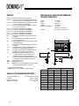
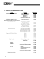
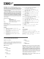
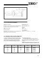
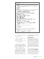
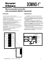
The DOMINO-1 microcontroller is a rugged, miniature
controller with a fast, control-oriented, processor masked
BASIC interpreter. DOMINO-1 programs can be entirely BASIC
or a mixture of BASIC and assembly language routines with a
BASIC CALL instruction.
DOMINO-1 is designed to be a 100% stand-alone, lowpower, embedded controller, which only requires a user to
apply power to function. DOMINO-1 is both RS-232A and RS485 compatible without extra components. Based on a CMOS
80C52 processor, DOMINO-1 provides a ROM-resident BASIC
interpreter, 32 KB of static RAM, 32 KB of nonvolatile
EEPROM, 12 parallel I/O lines, a 2-channel sample-and-hold
12-bit A/D converter, integral drivers/receivers for RS-422/ 485
and RS-232A communications.
Additional firmware enables program calls to directly read
frequency and period, set PWM pulse width and duty cycle,
communicate with I²C bus peripherals, and save programs to
EEPROM that can be auto started.
1 Ground
ADC0 19
2 Port 1.7
ADC1 18
3 Port 1.6
T1 17
4 Port 1.5
T0 16
5 Port 1.4
Line receiver
Line driver
SRAM
EEPROM
with utilities
80C52
with
BASIC
interpreter
*Int1 15
6 Port 1.3
*Int0 14
7 Port 1.2
Tx+ 13
8 Port 1.1
ADC
Tx– 12
9 Port 1.0
optional
Rx– 11
10 Rx+
8–12
2
+5
Gnd
Domino connector
+5V 20
Serial I/O
RS-232A, RS-422,
and RS-485
TTL I/O
Analog inputs
5-V power
Bottom view
1
Bottom view
© 1997 Micromint, Inc.
Rev. 2.0
January, 2000
1
™
DOMINO-1
PINOUT
Ground Single point digital and analog ground
Port 1.7 TTL I/O bit 7 (available through BASIC; optional
ADC uses Port 1.7 as CS input and I2C as CLK)
Port 1.6 TTL I/O bit 6 (available through BASIC; both ADC
and I2C use Port 1.6 as Data I/O)
Port 1.5 TTL I/O bit 5 (available through BASIC; optional
ADC uses P1.5 as CLK)
Port 1.4 TTL I/O bit 4 (available through BASIC)
Port 1.3 TTL I/O bit 3 (available through BASIC)
Port 1.2 TTL I/O bit 2 (available through BASIC)
Port 1.1 TTL I/O bit 1 (available through BASIC)
Port 1.0 TTL I/O bit 0 (available through BASIC)
Rx+
RS-422/485 noninverted serial (receive pair/recxmit pair)
Rx–
RS-422/485/232A inverted serial (receive pair/
rec-xmit pair/receive)
Tx–
RS-422/485/232A inverted serial (transmit pair/recxmit pair/transmit)
Tx+
RS-422/485 noninverted serial (transmit pair/recxmit pair)
*Int0
TTL interrupt input and general-purpose I/O bit
(available through assembly language)**
*Int1
TTL interrupt input and general-purpose I/O bit
(available as interrupt through BASIC)**
T0
Serial transmitter disable control, TTL timer/
counter input and general-purpose I/O bit
(available through assembly language)**
T1
TTL timer/counter input and general-purpose I/O
bit (available through assembly language)**
ADC1
Analog input 1 (0–5 V)
ADC0
Analog input 0 (0–5 V)
+5V
Regulated 5-V input for digital and analog circuitry
(analog inputs referenced to this input)
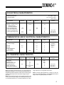
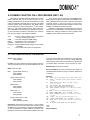
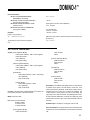
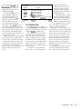
MECHANICAL AND ENVIRONMENTAL
CHARACTERISTICS
Length
Width
Height
Weight
Operating temperature
Humidity
A
TM
DOMINO
Operating temperature
Industrial
Storage temperature
Voltage on Vcc to Vss
2
Commercial 0°C to +70°C
–40°C to +85°C
–50°C to +125°C
0 to +7 V
Microcontroller
pin 1
MODEL
B
S/N
C
J I
E
D
G
F
H
* Triggered on the falling edge
** Refer to Section 5.0 (Controlling I/O Bits Directly)
ABSOLUTE MAXIMUM RATINGS
1.79 inches
1.1 inches
0.5 inches
18.5 grams
0 to +70°C
(optional –40 to +85 °C)
0 to 100% (noncondensing)
Dim
A
B
C
D
E
F
G
H
I
J
Inches
Min
Max
1.790
1.800
1.095
1.105
0.495
0.505
0.090
0.110
0.880
0.900
0.185
0.230
0.095
0.105
0.095
0.105
0.023
0.027
0.095
0.115
Millimeters
Min
Max
45.47
45.72
27.81
28.07
12.57
12.83
2.29
2.79
22.35
22.86
4.70
5.84
2.41
2.67
2.41
2.67
0.584
0.686
2.410
2.92
™
DOMINO-1
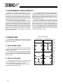
DC ELECTRICAL CHARACTERISTICS
Operating temperature
Operating voltage
Characteristic
Supply Voltage (Vcc)
Supply Current (Icc)
(RS-422/485 50-Ω
termination disabled)
Input Low Voltage (Vil)
Input High Voltage (Vih)
Output Low Voltage (Vol)
Output High Voltage (Voh)
Ta = 0°C to +70°C
Vcc = 4.75 V to 5.25 V
Vss = 0.0 V
Minimum
Typical
Maximum
Units
4.75
5.00
30-50
5.25
V
mA
0.9
5.5
V
V
V
V
V
–0.5
1.9
0.45
4.5
2.4
Condition
Iol=1.6 mA
Ioh=–10 µA
Ioh=–400 µA
COMMUNICATION LINE DC ELECTRICAL CHARACTERISTICS
Characteristic
Minimum
Typical
Differential Driver
Output Voltage
RS-422
RS-485
Maximum Receiver
Input voltage
ESD Protection
2.0
1.5
Maximum
Units
Condition
5.0
V
5.0
5.0
V
V
Unloaded
See Note 1
R=50 Ω
R=27 Ω
±14
V
V
2000
A/D CONVERTER CHARACTERISTICS
Characteristic
Resolution
Linearity Error
Offset and Gain Error
Voltage Reference
Analog Input Range
Analog Input Impedance
Minimum
12
4.5
Typical
Maximum
± 3⁄4
±2
5.0
–0.5 to Vcc+0.05
250k
Note 1: RS-232A is characterized as a ±5-V bipolar signal (as
opposed to RS-232C at ±12 V). Drivers and receivers are actually RS-422 and the interface is an RS-423 connection (single
ended to differential). Domino RS-232A Voltage output is
0-5V only.
Note 2: Two diodes are tied to each analog input which will
conduct when the input voltage is one diode drop below ground
or one diode drop above Vcc. To achieve absolute 0–5-V input
5.5
Units
Condition
bits
bits
bits
V
V
Ω
VREF is Vcc
See Note 2
See Note 3
range requires Vcc to be greater than 4.950 V.
Note 3: The ADC input impedance is a function of clock frequency. The sampling frequency of the DOMINO ADC built-in
utility results in a typical impedance of 250 kΩ.
3
™
DOMINO-1
1.0 PROGRAMMING CHARACTERISTICS
DOMINO-1 is a complete computer/controller in one tiny
package. The embedded BASIC interpreter and firmware provide the user with a direct means to enter and save an
autostarting control program without expensive development
tools. Such powerful advantages facilitate completing a programming task in record time. You can write, test, and save
code in nonvolatile storage directly on DOMINO-1.
The friendly, control-oriented BASIC command set allows
easy access to the integrated digital and analog I/O functions.
Conversion calculations are a breeze thanks to BASIC’s floating-point number crunching. Because of the power of a highlevel language such as BASIC, useful programs often take less
than a dozen programming statements. Nonetheless,
DOMINO-1 has over 30 KB of space reserved for your application code and the utilities. For application notes, please
visit www.micromint.com.
Even though DOMINO-1 is optimized for BASIC programs,
assembly language programs are easily accommodated as
callable routines. A DOMINO-1 application program can be all
BASIC, BASIC with callable assembly language routines, or
virtually all assembly language with the only BASIC command
being an introductory CALL.
DOMINO-1 contains all the communication interface hardware. It can be used standalone to monitor analog and digital
inputs and to provide control outputs directly to machine or
network interfaces. When connected serially, DOMINO-1 can
serve as a remote device, reporting monitored conditions to
your PC or receiving commands to control external components. If multiple DOMINO-1s are networked with a master PC
or another DOMINO-1, multidrop units can share information
collected throughout the network.
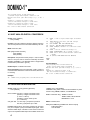
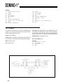
2.0 MEMORY MAP
The 64-KB memory is based on an 8051 microcontroller's
memory structure. The upper 32 KB is devoted to ROM and
the lower 32 KB to RAM.
Memory management
Development mode
Application mode
DOMINO utilities
DOMINO utilities
0FFFFH
0F000H
3
2
k
0E000H
0D000H
2.1 DEVELOPMENT MODE
When you're in the development mode, the lower 32 KB
of memory is used as temporary storage for BASIC's programs,
variables, and jump vectors.
The development mode is used to test and debug BASIC
programs. The top of the upper ROM space holds the utilities
which are callable functions complementing BASIC's floatingpoint commands.
2.2 APPLICATIONS MODE
Finished BASIC programs are saved in the upper 32 KB
of nonvolatile ROM space along with the utilities. BASIC programs can be autoexecuted on powerup or reset.
The lower 32 KB of RAM space is used for storage of
temporary variables and jump vectors.
4
E
E
P
R
O
M
0C000H
0B000H
0A000H
User’s program
autostart information
09000H
08000H
07000H
3
2
k
06000H
(when necessary)
interrupt vectors
(when necessary)
interrupt vectors
S
R
A
M
05000H
04000H
03000H
02000H
User’s program
BASIC’s external data
01000H
BASIC’s external data
00000H
™
DOMINO-1
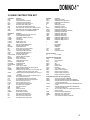
3.0 BASIC INSTRUCTION SET
Command
RUN
CONT
LIST
LIST#
NEW
NULL
RAM
ROM
XFER
Function
Execute a program
Continue after a stop or Control-C
List program to the console device
List program to serial printer port (P1.7)
Erase the program stored in RAM
Set null count after carriage return/line feed
Evoke RAM mode, current program in read/write memory
Evoke ROM mode, current program in ROM/EPROM
Transfer a program from ROM/EPROM to RAM
Statement
BAUD
CALL
CLEAR
CLEARS
CLEARI
CLOCK1
CLOCK0
DATA
READ
RESTORE
DIM
DO
UNTIL
WHILE
END
FOR-TO-{STEP}
NEXT
GOSUB
RETURN
GOTO
ON GOTO
ON GOSUB
IF-THEN-{ELSE}
INPUT
LET
ONERR
ONTIME
Function
Set data-transmission rate for line-printer port
Call assembly-language program
Clear variables, interrupts, and strings
Clear stacks
Clear interrupts
Enable real-time clock
Disable real-time clock
Data to be read by READ statement
Read data in DATA statement
Restore READ pointer
Allocate memory for arrayed variables
Set up loop for WHILE or UNTIL
Test DO loop condition (loop if false)
Test DO loop condition (loop if true)
Terminate program execution
Set up FOR...NEXT loop
Test FOR...NEXT loop condition
Execute subroutine
Return from subroutine
GOTO program line number
Conditional GOTO
Conditional GOSUB
Conditional test
Input a string or variable
Assign a variable or string a value (LET is optional)
ONERR or GOTO line number
Generate an interrupt when time is equal to or greater than
ONTIME argument; line number is after comma
GOSUB to line number following ONEX1/ when INT1 pin is
pulled low
Print variables, strings, or literals, P. is shorthand for print
Print to serial printer port (P1.7)
Print hexadecimal mode with zero suppression
Print hexadecimal mode with no zero suppression
PH0.# to serial printer port (P1.7)
PH1.# to serial printer port (P1.7)
Push expressions on argument stack
Pop argument stack to variables
Pulse-width modulation
Remark
Return from interrupt
Break program execution
Allocate memory for strings
Evoke user console input routine
Evoke BASIC console input routine
Evoke user console output routine
Evoke BASIC console output routine
ONEX1
PRINT
PRINT#
PH0.
PH1.
PH0.#
PH1.#
PUSH
POP
PWM
REM
RETI
STOP
STRING
UI1
UI0
UO1
UO0
Operator
CBY( )
DBY( )
XBY( )
GET
IE
IP
PORT1
PCON
RCAP2
T2CON
TCON
TMOD
TIME
TIMER0
TIMER1
TIMER2
+
/
**
*
.AND.
.OR.
.XOR.
Function
Read program memory
Read/assign internal data memory
Read/assign external data memory
Read console
Read/assign IE register
Read/assign IP register
Read/assign I/O port 1 (P1)
Read/assign PCON register
Read/assign RCAP2 (RCAP2H:RCAP2L)
Read/assign T2CON register
Read/assign TCON register
Read/assign TMOD register
Read/assign real-time clock
Read/assign TIMER0 (TH0:TL0)
Read/assign TIMER1 (TH1:TL1)
Read/assign TIMER2 (TH2:TL2)
Addition
Division
Exponentiation
Multiplication
Subtraction
Logical AND
Logical OR
Logical exclusive OR
Stored Constant
PI
PI - 3.1415926
Operators-Single Operand
ABS( )
Absolute value
NOT( )
One’s complement
INT( )
Integer
SGN( )
Sign
SQR( )
Square root
RND
Random number
LOG( )
Natural log
EXP( )
“e” (2.7182818) to the X
SIN( )
Returns the sine of argument
COS( )
Returns the cosine of argument
TAN( )
Returns the tangent of argument
ATN( )
Returns the arctangent of argument
Utility Calls (executed as CALL {address})
PROG
Save the current program in EEPROM
PROG1
Save data-transmission-rate information in EEPROM
PROG2
Save data-transmission-rate information in EEPROM and
execute program after reset
PROG3
Save data-transmission-rate information in EEPROM and saves
MTOP
PROG4
Save data-transmission-rate information in EEPROM and
execute program after reset
ADC
read 0–5-V input on AD0 or AD1, measurement returned as
floating-point value
PWM
continuous background PWM tasking
FREQ
measurement of TTL input frequency
PERIOD
measurement of TTL input period
I2C
communication with external I2C peripherals
5
™
DOMINO-1
3.1 Domino Utilities Function Calls
Feature
12- bit Analog-Digital Conversion
8-Bit Analog-Digital Conversion
NOTE: Only available when connected externally
Pulse-Width Modulation
Function
Single-ended channel 0
Single-ended channel 1
Differential +/Differential -/+
Single-ended channel 1 & 0
Call Address
0F000H
0F008H
0F010H
0F018H
0F020H
Single-ended channel 0
0F080H
Start PWM0 using TIMER0
and *INT0 ad outputs
Stop PWM0 immediately
Start PWM1 using TIMER1
and *INT1 ad outputs
Stop PWM1 immediately
0F064H
0F06CH
Period and Frequency
Start measurement on*INT0
Start measurement on *INT1
Retrieve measurement on INT0
Retrieve measurement on INT1
0F070H
0F074H
0F078H
0F07CH
Program the EEPROM (PROGx)
PROG
PROG1
PROG2
PROG3
PROG4
0FF00H
0FF08H
0FF10H
0FF18H
0FF20H
I2C Byte Transfer
Retrieve Registered Byte
Send Byte
Retrieve Byte
0F12CH
0F120H
0F124H
Initialize
Hook into UI0/1 BASIC command
0F110H
0F100H
0F108H
Initialize
Clear display and home cursor
Display $(0) string
0F030H
0F038H
0F040H
Hook into UI0/1 BASIC command
0F050H
2
I C Beeper
2
I C Keypad
I 2C LCD
Utilities Version Number
6
0F060H
0F068H
0FFF0H
™
DOMINO-1
4.0 DOMINO FUNCTION CALL PROCEDURES (REV 1.00)
Micromint has included additional utilities with its built-in
BASIC interpreter. Not only do you have the power of a full
floating-point BASIC, but you also have extra functions to help
make your application extremely easy to produce. The added
functions include analog measurement, dual PWM outputs,
dual period/frequency input measurements, I2C bus compatibility (e.g., LCD output and keypad input), and program storage in EEPROM for autostarting your application on powerup. These functions are written in assembler to be extremely
fast. They are simple to use straight from BASIC.
These function calls are loaded into the EEPROM above
BASIC program storage by a utility loader. The DOMINO-1 firmware is preloaded at the factory prior to shipment. Should it be
accidently erased or need to be revised, it can be reprogrammed using the bootstrap loader diskette included in the
DOMINO-1 development software package.
DOMINO-1 is potentially reprogrammable even while soldered in an end-use application. This reprogramming reduces
obsolescence, making it possible for a user to upgrade current
DOMINO-1 stock with the latest enhancements.
ADC
read 0–5-V input on AD0 or AD1, measurement
returned as floating-point value
PWM
continuous background PWM tasking
FREQ
measurement of TTL input frequency
PERIOD measurement of TTL input period
PROG1–4 autoexecutable program storage into nonvolatile
EEPROM
I2C
communication with external I2C peripherals
4.1 12-BIT ANALOG-DIGITAL CONVERSION
Syntax: CALL {address}
POP {variable}
Function: The CALL initiates an analog-to-digital conversion.
The result is presented on the stack to be POPed by the user.
is a single-ended measurement (referenced to ground). Alternatively, these channels can be used as a single differential
input (neither is ground referenced but there is no greater than
5 V between them). Channel 0 is +input, channel 1 is –input.
Related Topics: 8-bit A/D Conversion
Mode: Command, Run
Use:
[single-ended channel 0]
CALL 0F000H
POP {variable}
Error Presentation: No errors presented. A CALL made to a
nonexistent ADC still returns a value on the stack, albeit one of
no meaning.
Example:
[single-ended channel 1]
CALL 0F008H
POP {variable}
10
20
30
[differential +/-]
CALL 0F010H
POP {variable}
40
50
60
[differential -/+]
CALL 0F018H
POP {variable}
70
80
90
[single-ended channel 1 & 0]
CALL 0F020H
POP {variable},{variable}
100
110
120
130
Description: The processor’s Port1 pins (P1.7 *CS, P1.6 Data,
and P1.5 CLK) are used to access either the internal LTC1298
(DOMINO-1A) or an externally connected LTC1298 (DOMINO1). The LTC1298 offers a number of different connection configurations. Two ADC input channels are available when each
PRINT "This program prints an A/D conversion"
PRINT " from two single-ended inputs: Channel
1 & 0"
INPUT"Measure and enter your VCC voltage
(e.g., 5.12)"P
CALL 0F020H: REM THE FUNCTION CALL
POP V1,V0: REM GETTING THE RESULTS
PRINT USING(0),"Channel 1’s conversion count
is",V1
PRINT " and the calculated voltage is",
PRINT USING(#.###), V1 * (P/4096)," volts"
PRINT USING(0),"Channel 0’s conversion count
is",V0
PRINT " and the calculated voltage is",
PRINT USING(#.###), V0 * (P/4096)," volts"
PRINT "Hit a <cr> to make another conversion"
: PRINT
IF (GET=0) THEN GOTO 130 ELSE GOTO 40
READY
>RUN
Program Output:
7
™
DOMINO-1
This program prints an A/D conversion
from two single-ended inputs: Channel 1 & 0
Measure and enter your VCC voltage (e.g., 5.12) ?
4.95
Channel 1’s conversion count is 254
and the calculated voltage is 0.310 volts
Channel 0’s conversion count is 1259
and the calculated voltage is 1.521 volts
Hit a <cr> to make another conversion
4.2 8-BIT ANALOG-DIGITAL CONVERSION
Syntax: CALL {address}
POP {variable}
Function: The CALL initiates an analog-to-digital conversion.
The result is presented on the stack to be POPed by the user.
Mode: Command, Run
Use: [single-ended channel 0]
CALL 0F080H
POP {variable}
Description: The processor’s Port1 pins (P1.7 *CS, P1.6 Data,
and P1.5 CLK) are used to access an externally connected
ADC0831 (DOMINO-1). The ADC0831 offers a single-ended
measurement (referenced to ground).
Related Topics: 12-bit A/D Conversion
Error Presentation: No errors presented. A CALL made to a
nonexistent ADC still returns a value on the stack, albeit one of
no meaning.
20
30
PRINT " from a single-ended input on Channel
0"
INPUT"Measure and enter your VCC voltage
(e.g., 5.12)"P
CALL 0F080H: REM THE FUNCTION CALL
POP V0: REM GETTING THE RESULTS
PRINT USING(0),"Channel 0’s conversion count
is",V0
PRINT " and the calculated voltage is",
PRINT USING(#.###), V0 * (P/256)," volts"
PRINT "Hit a <cr> to make another conversion"
: PRINT
IF (GET=0) THEN GOTO 100 ELSE GOTO 40
40
50
60
70
80
90
100
READY
>RUN
Program Output:
This program prints an A/D conversion
from a single-ended input on Channel 0.
Measure and enter your VCC voltage (e.g., 5.12) ?
4.95.
Channel 0’s conversion count is 54
and the calculated voltage is 1.044 volts.
Hit a <cr> to make another conversion
Example:
10
PRINT "This program prints an A/D conversion"
4.3 PULSE-WIDTH MODULATION
Syntax: PUSH {On time},{Off time},{Duration}
CALL {address}
where variable (On time) = integer 150–65535 counts
(Off time) = integer 150–65535 counts
(1 count = 1.085 µs)
(Duration) = integer 0–255 cycles
(0 = continuous)
and given that 1%–99% duty cycle pulses up to 60 Hz
50% duty cycle pulses up to 3 kHz
Function: Defines the on time (high), off time (low), and duration (# of complete cycles) for a PWM output signal. It also
starts the PWM output. A duration of zero means continuous
output. Two separate PWM outputs are available *INT0 uses
8
TIMER0 and T1 uses TIMER1.
WARNING: Using either of these functions disables any other
function using TIMER0, TIMER1, or INTERRUPT0.
BASIC commands using TIMER0: CLOCK1
TIMER1: PWM, LIST#, PRINT#
INTERRUPT 0: none
Mode: Command, Run
Use: [start PWM0 using TIMER0 and *INT0 as output]
PUSH 500,1500,0
CALL 0F060H
™
DOMINO-1
[stop PWM0 immediately]
CALL 0F068H
[start PWM1 using TIMER1 and T1 as output]
PUSH 500,1500,0
CALL 0F064H
[stop PWM1 immediately]
CALL 0F06CH
Description: Using the PWM function requires MTOP to be
set to 3FFFH (although the function call sets this, the user
should be aware that any variable used prior to this call is destroyed unless MTOP is preset to 3FFFH at the beginning of a
program).
TIMER interrupt vector locations (400BH–400DH and
401BH–401DH) and on time, off time, and duration values storage locations (4200H–420BH) are set up in RAM. The PWM
function call sets up the TIMER counts alternating between
the on-time value and the off-time value on each TIMER overflow until the duration value has been decreased to zero.
A separate function call can be made at any time to immediately shut down the PWM. Each on- and off-time count defined is the number of 1.085-µs tics the routine delays before
changing state. The minimum count is 150 (150 × 1.085 µs) or
163 µs. The max count is 65535 or 71 ms.
Related Topics: PWM (BASIC command) The BASIC-1
Interpreter’s PWM command halts execution of the BASIC program while it is being executed. PWM0 and PWM1 function
calls do NOT halt the execution of the BASIC program, but it
becomes a background task.
Error Presentation: No error are reported although any BASIC command which uses the timers is disabled (see Function
description above).
Example: This example sets up both PWM outputs with
continously varying 1–99% duty cycles.
10
20
30
40
50
60
70
80
90
91
100
110
120
130
140
150
160
170
180
190
191
200
210
FOR Y=150 TO 14700 STEP 300
PUSH Y
PUSH 15000–Y
PUSH 0
CALL 0F060H
PUSH 15000–Y
PUSH Y
PUSH 0
CALL 0F064H
FOR Z=1 TO 50: NEXT Z
NEXT Y
FOR Y=14700 TO 150 STEP –300
PUSH Y
PUSH 15000–Y
PUSH 0
CALL 0F060H
PUSH 15000–Y
PUSH Y
PUSH 0
CALL 0F064H
FOR Z=1 TO 50: NEXT Z
NEXT Y
GOTO 10
READY
>RUN
4.4 PERIOD AND FREQUENCY
Syntax: CALL {address} [Start measurement]
CALL {address} [Retrieve result]
POP {variable}
where variable (period count) = integer 0–65535
(0 = measurement started)
(1 = measurement in process)
(2 = overflow occured—signal too slow)
(60–65535 = counts between negative edges)
(1 count = 1.085 µs)
(period = 65 µs – 71 ms)
(frequency = 15 kHz – 15 Hz)
Function: The start measurement function call sets up the
edge-triggered input interrupts and timers used to measure
the period between two sucessive input edges. Two separate
input signals can be measured. Input *INT0 uses interrupt 0
and timer0 and input *INT1 uses interrupt 1 and timer1.
WARNING: Using either of these inputs disables any other function using the interrupts or timers. The timers and interrupts
may again be used after the function calls are complete.
BASIC commands using:
TIMER0: CLOCK1
INTERRUPT0: none
TIMER1: PWM
LIST#, PRINT# INTERRUPT1: ONEX1
Mode: Command, Run
Use: [Start a measurement on input *INT0]
CALL 0F070H
[Start a measurement on input *INT1]
CALL 0F074H
[Retrieve a measurement on input *INT0]
CALL 0F078H
POP P
[Retrieve a measurement on input *INT1]
CALL 0F07CH
POP P
9
™
DOMINO-1
Descripton: Using the PERIOD/FREQUENCY function requires MTOP to be set to 3FFFH (although the function call
sets this, the user should be aware that any variable used prior
to this call is destroyed unless MTOP is preset to 3FFFH at the
beginning of a program).
External interrupt vector locations (4003H–4005H and
4013H–4015H), TIMER interrupt vector locations (400BH–
400DH and 401BH–401DH) and period count storage locations (420CH–420FH) are set up in RAM. The start period measurement function call initializes the INTERRUPT and TIMER.
The retrieve measurement function call passes the measurement status back to the user via the stack. The status is indicated as follows:
POPed Value Meaning
0
waiting for input
1
measurement in process
2
overflow (input too slow or nonexistent)
other
counts in 1.085 µs intervals.
Related Topics: none
Error Presentation: No errors reported (see Function description above).
Example:
10
20
30
40
50
PRINT "This program lets you use the
frequency function"
PRINT "Apply the TTL frequency to pin *INT0
and/or *INT1"
CALL 0F070H: REM PERIOD COUNT ON *INT0
FUNCTION CALL
CALL 0F074H: REM PERIOD COUNT ON *INT1
FUNCTION CALL
CALL 0F078H: REM RETRIEVE COUNT ON *INT0
FUNCTION CALL
60
70
80
90
100
110
120
130
140
150
160
170
180
190
200
210
220
POP PC0: REM GET THE PERIOD COUNT
IF (PC0=2) THEN PRINT "The frequency is too
low on *INT0": GOTO 130
IF (PC0=0.OR.PC0=1) THEN GOTO 50
P=PC0*1.085: REM PERIOD TIME CALCULATION
FROM COUNT VALUE
PRINT "The period on *INT0 is",P," µs. The
frequency is",
F=1/P*1000000: REM FREQUENCY CALCULATION
FROM PC VALUE
PRINT F,” Hz”
CALL 0F07CH: REM RETRIEVE COUNT ON *INT1
FUNCTION CALL
POP PC1: REM GET THE PERIOD COUNT
IF (PC1=2) THEN PRINT "The frequency is too
low on *INT1": GOTO 210
IF (PC1=0.OR.PC1=1) THEN GOTO 130
P=PC1*1.085: REM PERIOD TIME CALCULATION
FROM COUNT VALUE
PRINT "The period on *INT1 is",P," µs. The
frequency is",
F=1/P*1000000: REM FREQUENCY CALCULATION
FROM PC VALUE
PRINT F," Hz"
PRINT "Hit a <cr> to take another sample":
PRINT
IF (GET=0) THEN 220 ELSE GOTO 30
READY
>RUN
Program Output:
This program lets you use the frequency
function
Apply the TTL frequency to pin *INT0 and/or *INT1
The frequency is too low on *INT0
The period on *INT1 is 2164.575 µs. The frequency is
461.9 Hz
Hit a <cr> to take another sample
4.5 PROGRAM EEPROM (PROGx)
Syntax: CALL {address}
Function: The BASIC program residing in RAM and the appropriate header information (autostarting, baud rate, and
MTOP) is stored in EEPROM.
Mode: Command
Use: [PROG]
CALL 0FF00H
[PROG1]
CALL 0FF08H
[PROG2]
CALL 0FF10H
10
[PROG3]
CALL 0FF18H
[PROG4]
CALL 0FF20H
Description: These function calls act just like the BASIC-1
PROG commands. The BASIC commands are written for
EPROM. The EEPROM used here requires a different programming algorithm. The PROG function call replaces the
BASIC PROG command and saves only the program. The remaining PROGx function calls are similar in function to the
BASIC commands, but the function calls all save the program
and the startup characteristics in a single call.
Related Topics: PROG, PROG1, PROG2, PROG3, and
PROG4 (all BASIC commands)
™
DOMINO-1
Error Presenation:
ABORT, PROGRAMMING ERROR!
[EEPROM life exceeded]
ABORTED, ILLEGAL ACCESS ATTEMPT!
[storage space exceeded]
ABORTED, UNKNOWN RESULT CODE!
[unknown error]
ABORTED, NOTHING TO PROGRAM!
[no program in RAM]
Example:
[Type in your program:]
10
PRINT"Hello World!"
[Type RUN to verify it executes properly:]
Hello World!
>READY
[Now type the function call for PROG2:]
CALL 0FF10H
[you should see:]
STORING PROGRAM...
PROGRAM STORED!
[Whenever the power is disconnected and reconnected you
should see:]
Hello World!
RUN
4.6 I2C BYTE TRANSFERS
Syntax: [send registered BYTE]
PUSH {slave address * 100H + slave register}
PUSH {8-bit value}
CALL {address}
POP {16-bit value}
[retrieve registered BYTE]
PUSH {slave address * 100H + slave register}
CALL {address}
POP {16-bit value}
[send BYTE]
PUSH {slave address * 100H + 8-bit value}
CALL {address}
POP {16-bit value}
[retrieve BYTE]
PUSH {slave address * 100H}
CALL {address}
POP {16-bit value}
Function: Communication is attempted with an I2C device. An
8-bit value is passed to and from the device.
Mode: Command, Run
Use: where A=slave address
R=slave register
V=value to send
C=value retrieved
[send registered BYTE]
PUSH A*100H+R,V
CALL 0F128H
POP C
[retrieve registered BYTE]
PUSH A*100H+R
CALL 0F12CH
POP C
[send BYTE]
PUSH A*100H+V
CALL 0F120H
POP C
[retrieve BYTE]
PUSH A*100H
CALL 0F124H
POP C
Description: The address and register of the I2C slave device
is passed on the stack. If an 8-bit value is to be sent, it too
must be pushed onto the stack. A call is then made to send a
message using the I2C bus (P1.7 CLK and P1.6 DATA). The
routine returns a 16-bit value to the user on the stack. The
upper byte of the returned value is zero (000xxH) if the transfer was sucessful. Otherwise, it is set to all 1s (0FFxxH). If the
function was to retrieve a byte, it is in the lower 8 bits of the 16bit return.
Related Topics: I2C Beeper, I2C Keypad, and I2C LCD
Error Presentation: The upper 8 bits of the received byte are
masked to all 1s if the transmission is unsucessful or 0s if all is
OK.
11
™
DOMINO-1
Example:
10
20
30
40
50
60
70
80
90
100
PRINT"Turn ON the beeper"
A=046H
V=0DFH
PUSH A*100H+V
CALL 0F120H
POP C
IF (C<>0) THEN GOTO 180
PRINT"Hit a key to turn it OFF"
G=GET
IF (G=0) THEN GOTO 90
110
120
130
140
150
160
170
180
190
V=0FFH
PUSH A*100H+V
CALL 0F120H
POP C
IF (C<>0) THEN GOTO 180
PRINT"Now it’s OFF"
END
PRINT"Error in I2C communications"
END
4.6.1 I2C BEEPER
This function call assumes you’re using a Philips/Signetics
PCF8574 I 2C 8-bit I/O expander with the slave address
01000110 and piezobeeper on bit 5.
Description: The preassigned I2C slave address 46H is written to with a value of DFH to turn off bit 5. After a short delay, a
value of FFH is sent to turn bit 5 back on. The output bit can
sink 25 mA of current for, in this case, a piezoelectric beeper.
Syntax: CALL {address}
Related Topics: I2C Keypad, I2C LCD
Function: Bit 5 of the slave I/O expander is momentarily set
low to produce a short burst from an attached piezo-beeper.
Error Presentation: none
Mode: Command, Run
Example:
Use: CALL 0F110H
10
20
30
40
12
PRINT"Beep the beeper"
CALL 0F110H
PRINT"That’s it!"
END
™
DOMINO-1
4.6.2 I2C KEYPAD
This function call assumes you’re using a Philips/Signetics
PCF8574 I 2C 8-bit I/O expander with the slave address
01000110 and input bits 0–4 from 74C922 data bits, input bit 7
from Q of 74HC74 clocked from grounded D by DAV from
74C922, and output bit 6 to set the 74HC74)
Syntax: [initialize]
CALL {address}
[hook into UI0/1 BASIC command]
CALL {address}
Function: The slave I/O expander is initialized by toggling
output bit 6 low and high to set the 74HC74. This clears the
DAV latch. The hook routines can be implemented to install
the keypad as the alternate console input device.
Mode: Command, Run
Use: [initialize]
CALL 0F100H
[hook into UI0/1 BASIC command]
CALL 0F108H
Description: To initialize the keypad, the preassigned I2C slave
address 46H is written to with a value of BFH to turn off bit 6. A
value of FFH turns bit 6 back on. The output bit sets a 74HC74
latch clearing any DAV which may have clocked the grounded
D input. The DAV signal is generated by a 74HC922 whenever
a key is pressed. The keyboard can be read through an I2C
read BYTE routine. If bit 7 is low, then the lower 4 bits contain
keypad data. The user must reinitialize the keyboard (clear the
DAV) after each key read.
Alternatively, and much easier, the second function hooks
the keypad into the alternate console input device. Using the
hook function requires MTOP to be set to 3FFFH (although the
function call sets this, the user should be aware that any variable used prior to this call is destroyed unless MTOP is preset
to 3FFFH at the beginning of a program). Custom console input vector locations (4033H–4035H) and custom console status check vector locations (4036H–4038H) are set up in RAM.
Related Topics: I2C BYTE transfers, I2C LCD, UI0 and UI1
(BASIC commands)
Error Presentation: none
Example:
10
20
30
40
50
60
70
80
90
100
110
120
130
140
150
160
MTOP=03FFFH
PRINT"Initialize the Keypad"
CALL 0F100H
PRINT"Hook into the alternate console input"
CALL 0F108H
PRINT"Hit a key on the keyboard to swap to
keypad input"
G=GET
G=GET: IF (G=0) THEN GOTO 80
PRINT: PRINT"Now swapping to keypad input"
UI1: REM CHANGE TO ALTERNATE CONSOLE INPUT
PRINT"Hit a key on the keypad to swap to
keyboard input"
G=GET
G=GET: IF (G=0) THEN GOTO 130
PRINT: PRINT"Now swapping to keyboard input"
UI0: REM CHANGE TO PRIMARY CONSOLE INPUT
GOTO 60
13
™
DOMINO-1
4.6.3 I2C LCD
This function call assumes you’re using a Philips/Signetics
PCF8574 I 2C 8-bit I/O expander with the slave address
01000010 and output bit 0–3 to the (LM034—4x20) LCD data
bits 4–7, output bit 4 to the LCD RS pin, and output bit 5 to the
LCD E pin).
Syntax: [initialize]
CALL {address}
[clear display & home cursor]
CALL {address}
[display $(0) string]
CALL {address}
[display a character]
CALL {address}
[hook into UI0/1 BASIC command]
CALL {address}
Function: The LCD must be initialized through the slave I/O
expander. This sets up the LCD in nibble mode with a 4 × 7
character matrix and invisible cursor. The LCD is cleared and
the cursor set to row1 column 1. Once initialized, the LCD can
be cleared and cursor sent home at any time. The first string,
$(0), can be directed to the LCD without using console redirection (UO1).
If you choose to use console redirection (UO1), the characters are handled one at a time. Console redirection can be
invoked once the hooks are installed for the BASIC UI1 command.
device. The use of the BASIC U01 command redirects all output automatically to the LCD display. Once hooked, characters are printed on a character by character basis. Characters
between 20H and 7FH are displayed. Those above 7FH are
used as cursor control. A <cr> moves the cursor to the begining
of the next (or first) line. Using the hook function requires MTOP
to be set to 3FFFH (although the function call sets this, the
user should be aware that any variable used prior to this call is
destroyed unless MTOP is preset to 3FFFH at the beginning
of a program).
Custom console output vector locations (4030H–4032H)
and custom list@/print@ vector locations (403CH–403EH) are
set up in RAM.
NOTE: LCD output routines are considerably slower than
console output, therefore care must be taken when using redirected (UO1) output to the LCD while using the BASIC-1
interpreter’s INPUT $(0) command. Input characters can be
lost while the previous character’s ECHO is being displayed
when you run above 4800 bps. You can either use a data rate
of less than 9600 or redirect console output to the primary (serial port) until after the INPUT statement. Then, when input is
complete, redirect the console output to the LCD and PRINT
$(0).
Related Topics: I2C BYTE transfers, I2C Keypad, U01 and UO0
(BASIC commands)
Error Presentation: none
Mode: Command, Run
Example:
[direct string output to the LCD]
Use: [initialize]
CALL 0F030H
[clear display & home cursor]
CALL 0F038H
[display $(0) string]
CALL 0F040H
[hook into UI0/1 BASIC command]
CALL 0F050H
10
20
30
40
50
60
70
80
MTOP=03FFFH
STRING 82,80
PRINT"Initialize the LCD"
CALL 0F030H
PRINT"Now all input strings will be displayed
on the LCD"
INPUT $(0)
CALL 0F040H: REM PRINT $(0) TO LCD
GOTO 60
[redirecting the PRINT command to the LCD as the secondary console output device]
Description: To initialize the LCD, the preassigned I2C slave
address 42H is used as an output port. The initialization data
is sent to the output port to place the LCD in nibble mode with
a 4 × 7 character matrix and invisible cursor. The clear display
and home cursor function is called to complete the initialization. Clearing the display and homing the cursor can be used
any time after the LCD has been initialized. Since the LCD
does not clear from the end of a print string to the end of the
LCD line, you will find this function call necessary to keep the
screen clean.
Displaying a string is easy without console redirection. The
first string, $(0), can be displayed on the LCD by using a simple
function call. This displays all characters in the string (normally
unprintable characters may be displayed as Kana characters).
Alternatively, and much easier to use, the console ouput
device can be hooked in as the secondary or alternate output
14
10
20
30
40
50
60
70
80
90
100
110
120
MTOP=03FFFH
STRING 82,80
PRINT"Initialize the LCD"
CALL 0F030H
PRINT"Hook into the secondary console output
(LCD)"
CALL 0F050H
PRINT"Now all further output will be displayed
on the LCD"
INPUT $(0)
UO1: REM CHANGE TO SECONDARY CONSOLE OUTPUT
DEVICE
PRINT $(0)
UO0: REM CHANGE TO PRIMARY CONSOLE OUTPUT
DEVICE
GOTO 70
™
DOMINO-1
4.7 UTILITIES VERSION NUMBER
Syntax: CALL {address}
Related Topics: none
Function: The CALL initiates a sign-on message displaying
the version number of the utilities presently installed.
Error Presentation: none
Mode: Command, Run
READY
>CALL 0FFF0H
Example:
Use: CALL 0FFF0H
Program Output:
Description: Version identification, which is embedded in the
utilities, is sent to the active console output.
DOMINO FLASH EXTENSION x.xx IS RESIDENT
5.0 CONTROLLING I/O BITS DIRECTLY
Since it isn't possible to directly set or reset bits on Port 3
from BASIC-1, it is necessary to call short machine language
routines to do the job. The routines consist of three bytes.
The first is either a SETB instruction (D2) or a CLR instruction (C2). The second specifies a bit address. Finally, the
third is a RET instruction (22).
The following table details the necessary routines for
each of the Port 3 bits. The program example shows how to
insert the routines into memory from BASIC-1 and how to
call them.
NOTE: All data in BASIC-52 must begin with a numeric value
or else it is interpreted as a variable. (ex: xby(3200h) = 0D2)
Pin
Bit
Name
To Set
To Clear
P3.0
P3.1
P3.2
P3.3
P3.4
P3.5
B0
B1
B2
B3
B4
B5
RxD
TxD
Int 0
Int 1
T0
T1
D2 B0 22
D2 B1 22
D2 B2 22
D2 B3 22
D2 B4 22
D2 B5 22
C2 B0 22
C2 B1 22
C2 B2 22
C2 B3 22
C2 B4 22
C2 B5 22
15
™
DOMINO-1
Example:
The following code is an example for using INT 1 (P3.3) as
an output bit.
100
110
MTOP=31000: REM Set MTOP Lower
XBY (32000)=0D2H: XBY(32001)=0B3h:
XBY(32002)=022H
REM Put INT 1 Set Program at 32000
120
150
XBY(32100)=0C2H: XBY(32101)=0B3H:
XBY(32102)=022H
REM Put INT 1 Reset Program at 32100
Call 32000: REM INT 1 On
Call 32100: REM INT 1 Off
Goto 200
160
200
210
222
Note: RAM locations and assembly code can be expressed
in decimal, hex, or both.
6.0 UPDATING THE DOMINO UTILITIES
The utilities reside in the uppermost portion of the memory
map. The utilities are placed in nonvolatile memory so they
remain along with your saved autostarting BASIC program,
even after power has become disconnected. The user can take
advantage of updated utilities (when available) by simply reloading them. This is a two-step process.
First, a utilities loader program (LOADUTIL.BAS) is entered into DOMINO. When this program is run, you are
prompted to download the actual utilities hex file
(UTIL_xxx.HEX). The LOADUTIL.BAS program reads in each
paragraph of the hex file, converting and storing it in RAM.
When the hex file has been read, “load sucessful,” “call address = xxxx,” and “total checksum = xxxxx” messages are
displayed. The total checksum should match the one included
in the UTIL_100.DOC file. This file also contains any last-minute
information you should be aware.
Second, if you have verified that all is correct, you may
transfer the utilities using the direct command “CALL xxxx” as
displayed in the above message. You get transfer status and a
sign-on banner when the utilities have been transfered into
nonvolatile EEPROM.
7.0 GETTING STARTED
Although you can use any communication software with
DOMINO, Host-1 is a convenient and friendly interface between
your PC and DOMINO. Host-52 can be used on any DOS-compatible PC with 640 KB of conventional memory. To use Host52 with DOMINO, you need two serial ports. COM1 for the serial connection to DOMINO and COM2 for your serial mouse.
(If you use COM1 for your serial mouse, you may select an
alternate COM port for the DOMINO through the Serial Option
of the Main Menu.)
Connect the DOMINO hardware to the PC’s serial port
and turn on the power to the DOMINO. At this point, unless
you already have an autostart program in DOMINO, it waits to
receive a space character. (If you are using a simple comm
program like Procomm to communicate with DOMINO, remember that DOMINO sets the baud rate when a space character
is entered. Any other entry confuses DOMINO. You also need
to power DOMINO off and on again if the first character
DOMINO receives is NOT a space.)
From the DOS command line, type in Host-52 from the installed directory. Host-52 sets up the screen into windows. The
top window is the editing window where you input and revise
your programs. The middle window is the console output window where you see DOMINO’s output. The narrow bottom window is the console input window where you can type direct
commands to DOMINO. You can activate either the editor (top
window) or the console (bottom two windows) by clicking on
them with the mouse.
Host-52 automatically sends out a space character in an
attempt to make contact with the DOMINO. You receive an OK
16
message if all is well.
Click on the top window. Host-52 automatically numbers
your BASIC program’s lines. Enter this single line where Host52 has entered the line number 10.
10
PRINT"Hello World"
Now click on the console window, then the PROGRAM
item of the menu bar, and then on SEND ALL. Host-52 sends
the BASIC code from its editor to DOMINO.
Click on the RUN item on the menu bar and then on START.
Host-52 passes the run command to DOMINO and your program executes (out of RAM).
Hello World
READY
>
You can start the program from the console input window by
typing:
RUN<cr>
Hello World
READY
>
This can be saved as an autostart program by typing:
™
DOMINO-1
CALL 0FF20H<cr>
SAVING PROGRAM...
PROGRAM SAVED!
Remove power from the DOMINO and then power it back up.
The program automatically runs.
Please read the Host-52 Develop System for BASIC-1 CPUs
for complete information on using Host-52, the BASIC-1 Programming for more on BASIC’s command syntax, and this
manual for more on using the DOMINO Utilities.
Hello World
READY
>
Devices sold by Micromint are covered by the warranty and patent indemnification provisions appearing in its Terms of Sale only. Micromint makes no warranty, express, statutory,
implied, or by description regarding the information set forth herein or regarding the freedom of the described devices from patent infringement. Micromint makes no warranty of
merchantability or fitness for any purposes. Micromint reserves the right to discontinue
production and change specifications and prices any time and without notice. This product
is intended for use in normal commercial applications. Applications requiring extended
temperature and unusual environmental requirements, or applications requiring high reliability, such as military, medical life support or life-sustaining equipment, are specifically
not recommended without additional processing by Micromint for such application.
17
™
DOMINO-1
APPENDIX 1.0
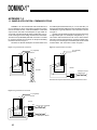
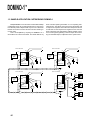
1.1 SAMPLE APPLICATION: COMMUNICATIONS
DOMINO-1 can communicate with other serial devices at
up to 19,200 bps. It can be connected in one of three configurations: RS-232A, RS-422, or RS-485. DOMINO-1’s RS-232A
output can be used with most full-duplex PC-type serial devices which normally handle RS-232C provided they can reconcile receiving the lower-voltage transmit level of RS-232A.
This three-wire (Tx/Rx/GND) RS-232A connection is created
by using the RS-422 input receivers as simple level-shifting
inverters as shown in Figure 1.
RS-422 is an alternate full-duplex connection which uses
two twisted-pair transmission lines (i.e., Tx+/Tx–/Rx+/Rx–) offering long transmission paths and noise-cancelling techniques.
This distance is typically 4000 feet. This connection is shown
in Figure 2.
RS-485 is similar to RS-422 with the exception that it uses
a single twisted pair in a half-duplex arrangement (i.e., +/-).
This means data transmissions must use the same twistedpair path to travel in both directions, requiring a simple protocol of only one unit seizing the transmission pair at a time while
all others listen. This connection is shown in Figure 3.
Figure 1—Typical RS-232A connections
Figure 3—Typical RS-485 connections
+5 V (regulated)
Ground
+5 V (regulated)
Ground
20
20
1
1
1
14
13
12
12
10
11
11
RS-485
Bottom view
RS-232A
Bottom view
1
–
Twisted pair to other
multidrop units
+
Note: RS-485 requires master-slave protocol and direction control
13
25
Figure 2—Typical RS-422 connections
+5 V (regulated)
Ground
20
1
RS-422
1
13
12
11
10
Rx–
Receive pair to transmitter
Rx+
1
Tx–
Bottom view
Tx+
18
Transmit pair to receiver
™
DOMINO-1
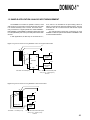
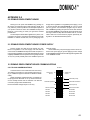
1.2 SAMPLE APPLICATION: ANALOG INPUT MEASUREMENT
The DOMINO-1A contains an optional 2-channel, 12-bit
A/D converter. The converter is a Linear Technology LTC1298.
It is mounted internally in the A version, but can be externally connected to a regular parallel I/O model DOMINO-1.
Both DOMINO-1 and DOMINO-1A firmware support ADC calls
for 8-bit (ADC0832) and 12-bit (LTC1298) dual-channel ADC
devices.
In both applications, the ADC chip is connected to P1.7,
P1.6, and P1.5 as described in the pinout listing. When an
ADC is connected, these port lines shared functions. The user
must take care not to confuse functions with random outputs
to these lines.
The example below shows ADC connections for using
DOMINO-1A with the optional internal ADC or DOMINO-1 with
an external ADC attached.
Figure 1—Typical connections for using DOMINO-1 with a user-supplied external ADC
+5
20
+5
1
2
1
3
+12
8
Vcc
CS
IN0
4
7
2
CLK
T300
temperature
probe
ADC0832
6
Bottom view
+12
SOUT
IN1
5
SIN
3
GND
4
8-bit ADC = 20 mV/bit (2°F)
T300
temperature
probe
T300 — Micromint’s Fahrenheit probe
-40°F (2.1 V) – +230°F (4.8 V)
10 mV/°F
Figure 2—Typical connections for using DOMINO-1A with its internal ADC
+5
20
19
1
18
+12
T300
temperature
probe
+12
Bottom view
12-bit ADC = 1.2 mV/bit (.12°F)
T300
temperature
probe
T300 — Micromint’s Fahrenheit probe
-40°F (2.1 V) – +230°F (4.8 V)
10 mV/°F
19
™
DOMINO-1
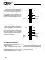
1.3 SAMPLE APPLICATION: NETWORKING DOMINO-1
Multiple DOMINO-1s can be used in a networked multidrop
configuration using only a single twisted pair for communication. Network protocol requires that only one unit is allowed to
transmit on the line at a time. All other units are “listening” in
receive mode.
This is accomplished by requiring one DOMINO-1 or a
device like a PC to be the net master. The master talks to any
+5
Domino #3: Slave
slave unit either passing information to it or requesting information from it. The slaves must never answer the master until
a response is requested. The master then relinquishes the net
to that slave for the response and regains the net when the
slave is finished. This arrangement enables multiple controllers to work together gathering numerous inputs and controlling innumerable outputs, independent of the system’s size.
+5
Domino #4: Slave
20
+12
20
+12
1
19
T300
temperature
probe
2
4
13
1
19
T300
temperature
probe
3
2
4
13
10
10
11
12
11
12
Beeper
Bottom view
Beeper
Bottom view
–
–
+
+5
Domino #2: Slave
100Ω
+
Twisted pair
+5
Domino #1: Master
Relay 0
20
+12
+12
20
1
19
T300
temperature
probe
1 2
2
4
13
3
3
4
13
Relay 1
10
10
11
12
Bottom view
Beeper
Bottom view
–
+
1k
100Ω
1k
20
+12
11
12
–
+
3
+5
Relay 2
+12
™
DOMINO-1
APPENDIX 2.0
2.0 DOMINO DEVELOPMENT BOARD
Packing so much power into DOMINO’s tiny package really keeps your finished product small and light weight. This
may, however, present a problem in the development phase of
your product. Micromint offers the DOMINO Development
Board as a tool to help you reach your goal in the shortest
possible time.
The development board offers regulated 5-V power, communication connection, an external LTC1298 ADC (for use with
DOMINO-1’s without internal ADC, and a prototyping area.
Simply add a regulated or unregulated power supply (7.5–12
V) and an RS-232 cable (DB-9M/DB-9M) to your PC’s serial
port. Any generic communications program may be used to
talk to DOMINO (pressing the space bar as the first character
sent enables DOMINO to automatically detect the baud rate in
the range of 300–19,200). Micromint offers Host-52, a combination editor and communications program specifically designed for use with 80C52 BASIC systems.
2.1 DOMINO DEVELOPMENT BOARD POWER SUPPLY
Domino requires very little current to operate. Any regulated or unregulated 7.5–12 VDC supply of at least 100 mA
can be used. The DOMINO development board accepts a 2.5mm power plug (available on most small wall transformer power
supplies). DOMINO's actual requirements are typically less than
15 mA, but you will probably want some additional power for
external circuitry.
NOTE: Make sure your power supply uses the center conductor of the power plug as ground. Applying reverse voltage
to the DOMINO development board damages the regulator and/
or the DOMINO module.
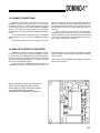
2.2 DOMINO DEVELOPMENT BOARD COMMUNICATIONS
2.2.1 RS-232A COMMUNICATIONS
Communications is set for RS-232A from the factory.
This setting is necessary for communicating with a PC (using no additional equipment besides a DB-9M to DB-9F
cable).
NOTE: RS-232A is characterized as a ±5-V bipolar signal (as opposed to RS-232C at ±12 V). Drivers and receivers are actually RS-422 and the interface is an RS-423
connection (single ended to differential).
RS-232A
1
Analog input
from J4
JP1
2
Analog input
from J2
1
JP2
2
Transmitter pull-down
Transmitter pull-up
Transmitter termination
1
Domino RS-232A Voltage output is 0-5V only.
JP3
2
Receiver pull-up
Receiver pull-down
RS-232A
10
Receiver termination
RS-422/485
RS-232A
7
RS-422-485
4
RS-422/485
1
RS-422-485
RS-232A
RS-232A
JP4
21
™
DOMINO-1
2.2.2 RS-422 COMMUNICATIONS
RS-422 communications requires two twisted pairs. One
pair connects the console transmitter to DOMINO’s receiver
while the second pair connects the console receiver to
DOMINO’s transmitter.
RS-422 uses two unidirectional data paths—one path for
each direction. The data transmission is differential, enabling
the noise picked up on the pairs to cancel itself out. Each
twisted pair should have termination enabled at each end of
the line. Pull-up and pull-down termination may be required,
but only at one end of each pair.
RS-422
1
Analog input
from J4
JP1
2
1
JP2
2
Transmitter pull-down
Transmitter pull-up
Transmitter termination
1
JP3
2
Receiver pull-down
RS-232A
10
RS-232A
Receiver pull-up
Receiver termination
RS-422/485
RS-422-485
RS-232A
JP4
RS-422/485
RS-232A
1
2.2.3 RS-485 COMMUNICATIONS
RS-485 communications requires one twisted pair to connect the console to DOMINO. RS-485 uses one data path, so
the drivers at each end must NOT be enabled at the same
time. The user is responsible for this rule NOT being broken.
The easiest protocol to follow is a master/slave(s) relationship, where the slaves DO NOT enable their transmitter
(respond) unless the master asks them to. The data transmission is differential allowing picked up noise to cancel itself out.
The twisted pair should have termination enabled at each
end of the line. Pull-up and pull-down termination may be required, but only at one end of the pair.
Analog input
from J2
RS-422-485
RS-485
1
Analog input
from J4
JP1
2
Analog input
from J2
1
JP2
2
Transmitter pull-down
Transmitter pull-up
Transmitter termination
1
JP3
Receiver pull-down
RS-232A
2
10
RS-232A
Receiver termination
RS-422/485
RS-422-485
RS-232A
RS-232A
Receiver pull-up
JP4
RS-422/485
1
RS-422-485
2.2.4 COMMUNICATION CONNECTIONS
RS-232A connection is made using a DB-9F to DB-9M
cable between the PC’s serial port and the DB-9F (J3) on the
DOMINO development board.
RS-422 connections are twisted wire pairs connected to
each set of screw terminal blocks on the DOMIMO development board. Connect the console’s transmitter (+) to DOMINO’s
screw terminal Rx (+) at T1 and the console’s transmitter (–) to
DOMINO’s screw terminal Rx (–) at T1. Connect the console’s
receiver (+) to DOMINO’s screw terminal Tx (+) at T2 and the
22
console’s receiver (–) to DOMINO’s screw terminal Tx (–) at
T1.
RS-485 connections are a single twisted pair connected
to both sets of screw terminal blocks on the DOMINO development board. Connect the twisted wire’s (+) lead to both of
DOMINO’s Tx and Rx (+) screw terminals on T1 and T2. Connect the twisted wire’s (–) lead to both of DOMINO’s Tx and Rx
(–) screw terminals on T1 and T2.
™
DOMINO-1
2.3 DOMINO CONNECTIONS
Except for communications connections, all pins on the
DOMINO are brought out to connector J2. If a 2 x 10 squarepin header is used in J2, a ribbon cable plugged onto J2 has
the same signal pinout as if it were plugged onto DOMINO
directly. This enables any external circuitry you’ve developed
for DOMINO to be used along with the DOMINO development
board.
If you choose to use the prototyping area on the DOMINO
development board, you can access to DOMINO’s I/O signal
at J2.
Analog input signals can come in through J2 or the ana-
log input connector J4. Choose the appropriate input path using JP1. For jumpers toward the edge of the board on JP1,
select analog input from connector J2. For jumpers away from
the edge of the board on JP1, select analog input from connector J4.
Jumper J5 offers connection between the development
board’s 5-V power and the power pin on J2. You may wish to
run your external circuitry from the development board’s power
or vice versa. Power is NOT connected between the two systems unless you determine it necessary.
2.4 ANALOG-TO-DIGITAL CONVERTER
DOMINO-1A contains a 2-channel 12-bit A/D converter.
For those of you who have purchased a DOMINO-1 without
the internal ADC, the DOMINO development board gives you
access to an external 2-channel 12-bit ADC using an LTC1298.
The utility routines within DOMINO can access this external
ADC as if it were installed internally.
The ADC inputs on the DOMINO development board are
available at two locations. The actual input from J2 or J4 is
selected through JP1. Input protection is installed on the ADC
inputs consisting of a low-pass filter and protection diodes to
VCC and ground.
NOTE: When using a DOMINO with internal ADC, please remove any external ADC.
Here’s a silkscreen of Domino’s Development
Board. The development board is used to
make it easy to connect the Domino module
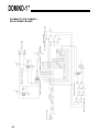
to external devices during product
development.The schematic is on page 23.
23
™
DOMINO-1
SCHEMATIC FOR DOMINO-1
DEVELOPMENT BOARD
24
Intel Hex to
BASIC Data
Statement
Translator
Jeff Bachiochi
get a ton of questions each month
(by both phone and Email) about using masked
BASIC-52 on the 8052 microcontroller.
The ever-increasing interest supports
my claim that BASIC offers a familiar
and friendly platform to learn embedded control. To the seasoned veteran,
it also provides an inexpensive development platform.
The whole thing started back in
1984 when Intel masked an 8-KB control-oriented BASIC interpreter, called
BASIC-52, into an NMOS 8052AH
DIP-style microcontroller. While Intel
no longer sells the chip, Micromint
continues to offer BASIC-52 masked
into low-power 8OC52 DIP and PLCC
packages.
with on-chip BASIC-52, writing
applications is a snap. No special compilers or assemblers are needed. You
just attach a terminal (or PC terminal
emulator) and type the lines of BASIC
in directly. The results can be stored
and executed immediately right there
on the target system.
Debugging the application is also
painless since all variables can be displayed and BASIC lines edited at any
time. For the majority of applications,
BASIC is all you need to collect, transform, or redirect data.
Of course, no single programming
language fits all control applications.
What a BASIC interpreter brings in
ease of use and program development,
it compromises in execution speed and
hardware to BASIC interfacing.
THE HARD FACTS
The 8031 core processor has four 8bit I/O ports. In an 8052 processor
with the masked BASIC, Port0 and
Port2 are used for the external address/
data bus. All eight bits on Port1 are
available through direct BASIC commands. The bits on Port3 have multiple functions and are available, but
only through assembly instructions or
assembly routines called from BASIC.
Many applications don’t need more
than eight I/O bits. However, if you
need more, you can add external I/O
peripheral chips. These can be easily
accessed using traditional PEEK and
POKE-type BASIC commands.
Some peripherals require interrupts
for tasks which need to take precedence over the BASIC program flow.
To facilitate this, BASIC-52 can directly respond to one of the two 803 lcore external interrupts. It also can
support a l-s tic clock for interrupts
based on elapsed time. The interrupt
servicing speed remains that of BASIC.
THENEEDFORSPEED
When the execution speed of a BASIC application program becomes
time-critical, consider supplementing
it with lower-level assembly language
for speed-sensitive tasks. The typical
execution time for a line of BASIC-52
is 230 ms, depending on the command. FOR/NEXT loops are the fastest
while P R I NT statements take considerably longer than the average.
Although assembly language executes in microseconds, it generally
takes hundreds of lines of code to accomplish what a single line of BASIC
can do.
On the other hand, task-specific
assembly-language code (e.g., reading
and storing A/D conversions) is much
faster than interpreted BASIC (for a
compiled BASIC the difference is not
as significant).
CALL OF THE WILD
So, I contend that you should use a
BASIC interpreter whenever and wherever it makes sense. When you need
more execution speed, consider compiled BASIC or callable task-specific
assembly language routines.
The BASIC-52 CALL 4200H statement saves a pointer to the next line of
BASIC code on the stack and then
jumps blindly to the address you give
#67 February 1996
Circuit Cellar INK
it (in this case, 4200H). The proOFFFFH
cessor now expects to fetch an
b)
assembly-language opcode to execute.
That’s how your assembly
EPROM
EPROM
routine gains control from BASIC.
When your routine has finished,
the R ETurn opcode returns control
to BASIC. The pointer to the next
8000H _______ __
line of BASIC is popped off the
8000H__________
7FFFH
7FFFH
MTOP
BASIC’s
MTOP
stack and execution of the BASIC
r-l
variables
application continues.
clrow down
Assembly
Let’s assume that all you need
routine
to do is set and clear an I/O bit
BASIC’s
normally unavailable to BASIC,
arrays
Redirected
like Tl (P3.5). First, you need a
grow up
JUMP vectors
SRAM
- - SRAM
place in memory to store the rouLowered MTOP
End of BASIC varies
with program size
End of BASIC varies
tine. You might want to place the
0
with program size
routine in ROM above the space
BASIC
where the BASIC program resides
Start of BASIC
application program
in autostart mode.
OOOOH
There’s one problem with this
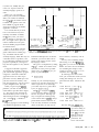
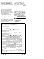
solution. You now have two proFigure 1-a) Af powerup, BASlC puts variable storage as high in RAM as possible. b) Modifying MOP protects a portion
grams which must be loaded propof memory for use by assembly language routines.
erly, one BASIC and the other
assembly language. While this may not
these locations, I started my code at
RAM from 200H upward. As the first
sound like much of a problem, it can
4200H.
statement, you need to add a line to
Let’s try some something simple
be a bookkeeping nightmare for longer
protect some memory for the assembly-language routine.
like turning on or off bit B5H (P3.5
programs, especially if you forget to
This goal is accomplished by setting Tl), which you can’t do directly from
keep the files together for easy maintenance.
BASIC. You don’t need an assembler
the MT0 P variable to an address lower
for something this simple. It only
than that set in the power-up initialI suggest an alternative approach.
ization. Let’s use 3FFFH, to give you
requires two opcodes: a S ETB (or C L R)
Try keeping the assembly routine as
instruction and a RETurn.
part of the BASIC application program
plenty of protected space.
By referring to the micro’s data
using DATA statements. While this
10 MTOP=3FFFH
approach involves an extra step to
book, you can find the correct bytes for
protect the necessary RAM space and
setting and clearing a bit. You can
poke the routine into memory each
place them into DATA statements like
Notably, if your assembly-language
this:
time the application is run, the process
routine were only three bytes long (and
is quite straightforward. Just look.
didn’t require the use an interrupt),
10000 REM Set I/O bit Tl
When you power up the 8OCS2
you would only have to protect three
b y t e s ( l 0 MTOP=7FFCH).
platform, you start out with an allo10010 DATA OD2H, OB5H:
REM SETB Tl
cated address space like that in Figure
With MT0 P reassigned to 3FFFH,
la. The processor has measured the
you now have the address space allo10020 DATA 022H: REM Return
cated as in Figure lb. Although you
10030 REM Clear I/O bit Tl
amount of RAM you have in the sys10040 DATA OC2H, OB5H:
may not require the interrupt jump
tem and assigns it to the variable MT0 P
REM CLR Tl
(let's assume MT0 P = 7FFFH for a
vectors which start at 4000H, I always
32.KB SRAM).
10050 DATA 022H: REM Return
protect them but leave them free of
code. You may need them eventually.
Begin by typing in (or downloading)
The first data byte, D2H, is the
(More on this later.) To stay clear of
your BASIC-52 application. It fills
assembly-language
opcode for setting an
I/O bit. The second
byte, R5H, is the bit
address where the
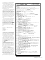
: 20 4200 00 ~~~~~~~~~~~~~~~~~~~~~~~~~~~~~~~~~~~~~~~~~~~~~~~~~~~~~~~~~~~~~~~~
7A
operation is to be
performed. The
Figure 2-a) A raw line of Mel hex looks like a jumble of characters. b) The line separated into its six major parts-start character, data
length, load address, mode, data, and checksum-becomes easier to deal with.
source code for this
I
I
#67 February 1996
Circuit Cellar INK
opcode follows in a remark statement
for documentation purposes only.
In the second statement, 22H is an
opcode which returns control (in this
case, to BASIC]. This hand-coding
method can be used when there is
little chance for error.
You’re welcome to hand-code larger
routines, but be advised that it’s extremely easy to miscode a statement,
especially one with relative jumps and
such. Do it as a exercise, and back it
up with output from an assembler. It’s
bad enough when your routine doesn’t
run due to an error in logic. Don’t add
coding errors to your debugging session!
Now, all you need to do is get these
six bytes into protected RAM where
they’ll be ready for you to call them.
I’ve suggested using 4200H as the
starting address. So, you need a BASIC52 routine which pokes the data bytes
into RAM at 4200H using the X B Y
statement. You can use a routine like
this:
20 FOR X = 4200H TO 4205H
30 READ V
40 XBY(X) = V
50 NEXT X
The FO R/N E X T loop assigns 4200H
to variable X It reads a byte and places
it into address location X. The address
is incremented, and the read-and-store
is repeated until X exceeds 4205H.
Once the data has been stored, it
remains in RAM until something overwrites it or the power is cycled off and
on. Your BASIC application can CALL
4200H toset Tl and CALL 4203H to
clear Tl.
You can even make the calls from
the command-line prompt to test
them. You quickly discover that if you
make a call to a location which either
has no routine or has a miscoded routine, anything can ,happen.
Anything can include totally locking up the system, so you may wish to
both check your routine carefully and
make sure it’s there before you call it
(at least the first time). At a minimum,
at least ensure the first byte at the
location you call is correct.
You can also sum all the code you
placed in RAM and compare the total
Listing l--This program, wriffen in a generic PC BASIC, translates an Mel hex file into an 80C52 BASlC
program and loads the Mel hex data info SRAM.
10 CLS
2 0 FLAG=0
30 REM This program prompts for an Intel hex file name,
40 REM reads the file in, and creates an output file. The
50 REM file can be appended to a 8OC52 BASIC program to load your
60 REM assembly routine into SRAM (located in combined
70 REM Data/Code space) for execution there.
80 1NPUT"What is the Intel hex filename? ",A$
90 OPEN A$ FOR INPUT AS i/l
1oc PRINT
1 1 0 PRINT"The output file will be called DATA.BAS."
120 1NPUT"What line number should it begin with? ",LINENUMBER
130 B$ = "DATA.BAS"
140 OPEN B$ FOR OUTPUT AS 112
150 IF EOF(1) THEN O$ = II": TEMP=LINENUMBER: GOT0 970
160 ON ERROR GOT0 950
170 INPUT i/l, I$
180 IF (MID$(I$,l,l) <> "."I THEN GOT0 930
190 PAIRCOUNT = VAL("&H"+MID$(I$,Z.Z))
200 LOADADDRESS = VAL("&H"+MID$(I$.4,4))
210 GOSUB 610
220 MODE = VAL("&H"+MID$(I$,8.2))
230 IF (MODE<>0 AND MODE<>11 THEN PRINT"Warning, mode must be 00"
240 IF (MODE=11 THEN PRINT"End of File"
250 FOR X=10 TO lO+(Z*(PAIRCOUNT-1)) STEP 2
260 IF (BYTECOUNT> THEN BYTECOUNT = 0: GOSUB 890:
LINENUMBER = LINENUMBER+lO
270 IF (BYTECOUNT= THEN 0s = II": TEMP=LINENUMBER: GOSUB 390:
GOSUB 580
280 O$ = O$ + 1, 0" + MID$(I$,X,2) + "H"
290 TOTALSUM = TOTALSUM + VAL("&H"+MIDB(IB.X.Z))
300 IF (BYTECOUNT<> THEN 08 = 08 + )1,"
310 BYTECOUNT = BYTECOUNT + 1
320 CHECKSUM = VAL("&H"+MID$(I$.10+2*PAIRCOUNT,2))
330 FOR COUNT = 2 TO 10+(2*(PAIRCOUNT-1)) STEP 2
340 CHECKSUM = CHECKSUM + VAL("&H"+MID$(I$,COUNT,2))
350 NEXT COUNT
360 IF (CHECKSUM AND 255) <> 0 THEN PRINT"Checksum error"
370 NEXT X
380 GOT0 150
390 REM Place the line number digits into a string
400 BLANKFLAG = 0
410 IF (TEMP<lOOOO) THEN GOT0 440
420 TEMPINTEGER = INT(TEMP/lOOOO): 08 = O$ + CHR$(TEMPINTEGER+48)
430 TEMP = TEMP TEMPINTEGER*lOOOO: BLANKFLAG = 1
440 IF (TEMP<lOOO) THEN GOT0 470
450 TEMPINTEGER = INT(TEMP/lOOO): O$ = 08 + CHR$(TEMPINTEGER+48)
460 TEMP = TEMP TEMPINTEGER*lOOO: BLANKFLAG = 1: GOT0 480
470 IF (BLANKFLAG= THEN O$ = 08 + "0"
480 IF (TEMP<lOO) THEN GOT0 510
490 TEMPINTEGER = INT(TEMP/lOO): 08 = 08 + CHR$(TEMPINTEGER+48)
500 TEMP = TEMP TEMPINTEGER*lOO: BLANKFLAG = 1: GOT0 520
510 IF (BLANKFLAG= THEN O$ = 08 + "0"
520 IF (TEMP<lO) THEN GOT0 550
530 TEMPINTEGER = INT(TEMP/lO): O$ = 08 + CHR$(TEMPINTEGER+48)
540 TEMP = TEMP TEMPINTEGER*lO: BLANKFLAG = 1: GOT0 560
550 IF (BLANKFLAG= THEN 08 = O$ + "0"
560 O$ = 08 + CHR$(TEMP+48)
570 RETURN
580 REM Add the word "DATA" to the string
590 O$ = 08 + " DATA '
600 RETURN
610 REM Track the start and finish address for each,segment
620 IF (FLAG<>01 THEN GOT0 650
630 START = LOADADDRESS: FINISH = LOADADDRESS + PAIRCOUNT 1:
#67 February 1996
Circuit Cellar INK
Listing P-continued
640 RETURN
650 IF (FINISH+l=LOADADDRESS) THEN FINISH = FINISH + PAIRCOUNT:
RETURN
660 GOSUB 690
670 FLAG = 0
680 GOT0 610
690 REM Append the loading routine for the DATA statement segment
700 IF (RIGHT$(O$,l)=", "1 THEN 08 = MID$(O$,l,LEN(O$)-1)
710 IF (RIGHT$(O$,l)<>" "1 THEN GOSUB 890:
LINENUMBER = LINENUMBER + 10
720 08 = IIn: TEMP = LINENUMBER: GOSUB 390
730 O$ = 08 + )I ST=0 : CT=": TEMP = TOTALSUM: GOSUB 390
740 GOSUB 890
750 LINENUMBER = LINENUMBER + 10
760 O$ = (1": TEMP = LINENUMBER: GOSUB 390
770 O$ = 08 + ' FOR X = '
780 TEMP = START: GOSUB 390
790 O$ = O$ + " TO "
800 TEMP = FINISH: GOSUB 390
810 08 = O$ + ’ : READ H : XBY(X)=H : ST=ST+H : NEXT X"
820 GOSUB 890
830 LINENUMBER = LINENUMBER + 10
840 08 = (1": TEMP = LINENUMBER: GOSUB 390
850 08 = 08 + ’ IF (CT<>ST) THEN PRINT (1
860 08 = 0$ + CHR$(34) + "DATA ERROR" + CHR$(34) + ’ : END":
GOSUB 890
870 LINENUMBER = LINENUMBER + 10: BYTECOUNT = 0
880 RETURN
890 REM Display and save present BASIC line
900 PRINT #2,0$
910 PRINT 08
920 RETURN
930 REM First character error in Intel hex paragraph
940 PRINT"Error. First character must be a I:"': CLOSE : END
950 REM Character error within Intel hex paragraph
960 PRINT"Error in input file": CLOSE: END
970 GOSUB 390: O$ = 08 + ' RETURN": GOSUB 890: CLOSE: END
to a known good total placed in the
BASIC program:
60 S = 0: C = 834
70 FOR X = 4200H TO 4205H
80 S = S +XBY(X)
90 NEXT X
100 IF (C<>S) THEN PRINT"Data
error": STOP
This is where I lose a bunch of
people. “I’m not gonna type in all
those DATA statements with the code
from my assembled source. My Intel
hex file is over 1 KB in size.”
There isn’t much I can say that
would convince them it would be
worth their while. So, this month I
present a piece of code, written in a
generic PC BASIC, which reads in an
Intel hex file and translates it into
BASIC-52 DATA statements. The out-
put can be appended to your BASIC-52
application program.
INTEL HEX FILES
When a source file is assembled
into a binary file, it contains no address information and no way-other
than the file size-of assuring that the
file has not been corrupted. When the
binary file is translated into an Intel
hex file, it becomes protected, if you
will. The binary data is cut into small
chunks, called lines or paragraphs,
and surrounded by additional information.
As you can see in Figure 2, each
Intel hex line begins with a ” : ” start
character followed by the number of
data bytes in the chunk (two hex characters) OOH-FFH. (Note that the chunk
must have data bytes which can be
loaded into successive addresses.) To
INK@
#67 February 1996
Circuit Cellar INK
keep the lines viewable on an
important information is
Code space
80column screen, the size of a
extracted, like load address,
address
Function
chunk is generally limited to
number of data bytes, data,
OOOOH
RESET
20H (that’s 32 binary bytes or
sum of the data, and legal
0003H
IEO (external interrupt 0)
hexadecimal pairs J.
checksum. Errors are flagged
OOOBH
TFO (timer 0 overflow)
The next four characters are
during processing.
0013H
IEl (external interrupt 1)
001 BH
TFl (timer 1 overflow)
the hexadecimal starting adAn output string is formed
0023H
RI & TI (serial-port interrupt)
dress for the first byte in the
using line-number informa002BH
TF2 & EXF2 (timer 2/Capture) (80 x 2 only)
chunk OOOOH-FFFFH. A twotion and the proper format for
character mode byte follows
BASIC-52 DATA statements.
Table l-The 8031 core inferrupt vectors require code memory space sfarfiag
at OOOOH.
the load address. If the mode
When the output string reachbyte is OOH, then data follows.
es eight data values, it’s writIf the mode byte is OlH, then it’s an
FILE TRANSLATION
ten to the output file, and the line
EOF marker. (Other mode bytes indiThe file HEXZBAS. BAS (Listing 1)
number counter increments.
cate extended addressing and are not
Meanwhile, if the next input line’s
was written in a generic PC BASIC and
used when the address space doesn’t
should be usable with any of the more
load address is not the next sequential
exceed 64 KB.) Assuming the mode
powerful BASICS available today.
address, the code is not sequential and
byte is OOH, the chunk of data follows
When run, it asks for the Intel hex
the new data must be handled as such.
in hexadecimal format.
file’s name and what BASIC-52 line
So, the last data byte in the last line
Finally, to keep errors from creeping
number to begin with. You should
must be the end of the last block and
in, a checksum byte is added. Since
answer with the file name you’d like
therefore the block’s ending load adevery line has a checksum byte, each
translated and a line number higher
dress. I now must create a FOR/NEXT
is individually protected. And, since
than any used in your BASIC-52 appliloop load routine for that last block.
each chunk of data comes along with
Remember the routine which loads the
cation (e.g., 10000). An output file
its load address, every data byte is
called DATA. BAS is created, and both
data into RAM?
placed exactly where it belongs, even if files are opened.
I’ve been keeping track of the sum
the lines somehow get out of seAs each line is read in from the
of the data within this block. Therequence.
Intel hex file, it is dissected. All the
fore, I can also allow the load routine
#67 February 1996
Circuit Cellar INK
of code is the reset vector jump. Since
BASIC-52 runs on powerup and this
vector is not shadowed like the others,
it can be discarded. Well, almost.
Instead, 4200H is the location BASIC would call to enter the routine. In
this example, there is never a return to
BASIC. The assembly-language routine
completely takes over until power is
shut down. Here, BASIC loads the
jump vectors and routines-once it
passes execution over to the routine, it
is never heard from again.
This situation, of course, is the
extreme. Why bother at all with BASIC once you are writing totally in
another language?
And rightly so. I do not advocate
the use of BASIC for every application.
But, I do like the friendly development
environment and the ease of getting an
application up and running.
As you have seen here, it is very
possible for BASIC-52 and assembly
routines to coexist. I hope I have demonstrated a way you can use the 8OC52
to have your cake (the power of BASIC)
and eat it too (call on the speed of
assembly language). Remember, when
all you need to do is tap, don’t use a
sledge. q
/eff Bachiochi (pronounced “BAH-keyAH-key”) is an electrical engineer on
Circuit Cellar INK’s engineering staff.
His background includes product
design and manufacturing. He may be
reached at [email protected].
428 Very Useful
429 Moderately Useful
430 Not Useful
What is the Intel hex filename? DEMOl.H:X
The output file will be called DATA.BAS. What line number should
it begin with? 10000
10000
10010
10020
10030
10040
10050
10060
10070
10080
10090
10100
10110
DATA OOZH, 042H, OOOH
ST=0 : CT=68
FOR X = 0 TO 2 : READ H : XBY(X)=H : ST=ST+H : NEXT X
IF (CT<>ST) THEN PRINT "DATA ERROR": END
DATA OOZH, 042H. 04DH
ST=0 : CT=145
FOR X = 35 TO 37 : READ H : XBY(X)=H : ST= ST+H : NEXT X
IF (CT<>ST) THEN PRINT "DATA ERROR" : END
DATA OOZH, 042H, 042H
ST=0 : CH=134
FOR X = 11 TO 13 : READ H : XBY(X)=H : ST= ST+H : NEXT X
IF (CH<>ST) THEN PRINT "DATA ERROR" END
10120 DATA OE4H, OF5H, 090H, OC2H, OD5H, OD2H, OD4H, 078H
10130 DATA 020H, OCZH, OD4H. 075H, 098H. 050H, 075H, 089H
10140 DATA OZOH, 075H, 08DH, OFDH, 085H, 08DH, 08BH, 075H
10150 DATA OB8H, OlOH, 075H, OA8H, 092H, 075H, 088H, 050H
10160 DATA 012H, 042H, 03FH, OFAH, OFBH, OF5H, 090H, OF4H
10170 DATA OF5H, 08CH, OEBH, 020H, OD5H, 004H, 003H. OOZH
10180 DATA 042H, 033H, 023H, OFBH, OF5H, 090H. 012H, 042H
10190 DATA 03FH. 06AH. 060H, OEEH, 06AH, 080H, OE4H, OE5H
10200 DATA OAOH, 022H, OCOH, OEOH, OB2H, OD5H, OEAH, OF4H
10210 DATA OF5H, 08CH, ODOH, OEOH, 032H, OCOH, OEOH, OCOH
10220 DATA ODOH, OCZH, 098H, 075H, ODOH, OlOH, OE5H, 099H
10230 DATA OF5H, OFOH, 064H, OODH, 070H, OOFH, 074H, OlFH
10240 DATA OC3H, 098H. OF4H, 060H, 013H, OFBH, OE4H, 018H
10250 DATA OF2H,,ODBH, OFCH, 080H, OOBH, 074H, 03FH, OC3H
10260 DATA 098H, OB3H, 050H, 004H, OE5H, OFOH, OF2H, 008H
10270 DATA ODOH, ODOH, ODOH, OEOH, 032H
10280 ST=0 : CT=18439
10290 FOR X = 16896 to 17020 : READ H : XBY(X)=H : ST=ST+H :
NEXT X
10300 IF (CHECKTOTAL<>STORETOTAL) THEN PRINT "DATA ERROR" : END
End of file OK
Figure 3-A ruun of fhe translation program demonstrates the kind of output you can expect from an Me/ hex
#67 February 1996
Circuit Cellar INK