1
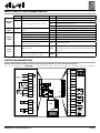
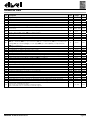
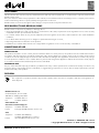
EWBC800
Controllers for blast chillers - Base
DESCRIPTION
The base is an electronics board controlling the basic functions of a blast chiller, combined with a capacitive touch keypad with display, called the user interface. The base is supplied ‘open’, and is equipped with a microcontroller, inputs and outputs.
TECHNICAL DATA
Classification
Electronic automatic control device (not safety) device to be integrated
Installation
Open board
Type of action
1.B
Pollution class
2
Material class
IIIa
Over voltage category
II
Nominal pulse voltage
2500 V
Ambient operating temperature
-5 - 55 °C
Ambient storage temperature
-30 - 85 °C
Operating environment and storage 10% - 90%
environment humidity (non-condensing)
Power supply voltage
100 - 240 Va +/- 10%, 50/60 Hz (switching)
Maximum consumption
5.5 W
Insulation class
2
Fire resistance category
D
Software class
A
Connectors
• For power supply, relay outputs: Faston connectors for cables with a cross-section of 2.5 mm2
• For inputs, opencollector digital output: screw-type terminal block for cables with a
cross-section of 2.5 mm2
• Connection to KEYB keypad: screw-type terminal block for cables with a crosssection of 2.5 mm2
• For TTL serial port: 5-way connector
Dimensions
92x121 mm
Buzzer
Present
MECHANICAL INSTALLATION
Do not install EWBC800 in places subject to high humidity and/or dirt; it is intended for use in sites with ordinary or normal levels
of pollution. Keep the area around the chiller cooling slots adequately ventilated. Base installation takes place inside the blast chiller,
with plastic spacers applied to the holes (A) already present.
A
A
A
A
A
A
EWBC800 - Technical sheet for base
A
Pg. 1/4
INPUT / OUTPUT / PORT CHARACTERISTICS
Number Specifications
Analogue
inputs
Digital
inputs
Digital
outputs
Serial
ports
Initials Description
1
NOT configurable, set PTC
3
Jointly configurable as PTC or NTC
2
5
PB1
Needle probe
PB2
Cold room probe
PB3
Evaporator probe (defrost)
PB4
Condenser probe
Voltage-free with closing current for DI
ground
PB5
Blast chiller door closing control microswitch
Relay R1 SPST, NO, 30 A, max. 250 V~ OUT1
Default compressor
Relay R2 SPDT 16 A max. 250 V~
OUT2
Default evaporator room fan
Relay R3 SPDT 8 A max. 250 V~
OUT3
Default condenser fan
Relay R4 SPST 8 A max. 250 V~
OUT4
Default door heating
Pressure switch
Opencollector OC for external relay
OUT5
connection, 12 Vc, 20 mA
Default NOT USED
TTL connector
TTL
Serial port to interface the parameters programming
key (Copy Card) or for connection to PC (by appropriate
interface)
KEYB
Serial port for connection between base and user interface
2
Screw connector on base side;
click-fit on keypad side, 3-way
ELECTRICAL CONNECTIONS
Always switch the blast chiller off before performing any maintenance on the electrical connections.
The wiring diagram for EWBC800 is shown in the figure below, in which the default loads are illustrated.
DEFAULT NOT USED
N
N
POWER
230 Vac
L
CELL
CELL
COND
COND
COMP
1
12V
33
OC
32
2
31
3
30
4
C
5
NO2
6
NC2
7
C
8
NC3
9
NO3
10
C
11
NO1
12
13
C
14
NO4
DOOR
EWBC800 - Technical sheet for base
29
R2
28
R3
R1
R4
TTL
KEYB
GND
27
DI
26
PB5
25
PB4
24
CPB
23
PB3
22
CPB
21
PB2
20
CPB
19
PB1
18
DOOR
PRESSURE SW
COND
DEFROST
CELL
Pg. 2/4
PARAMETER TABLE
Par. Description
Def
Range
U. M.
iSt
dOF
dOn
dF1
dF2
dF3
3.0
2
3
30
8
0
1.0...20.0
0...99
0...99
0...99
0...99
0...2
°C/°F
Min
Min
Min
hours
num
dF4
dF5
dF6
dr1
dr2
Fans
FR1
FR2
FR3
FR4
FR5
tP0
dEC
EP1
EP3
Edo
tdO
EnC
SLd
Uut
Prd
Prt
SCF
EPS
PPS
OFL
LAE
OFH
HAE
PS2
Regulation hysteresis
Compressor Protection Off/On (also valid at reset) Compressor Protection On/On
Enable/Maximum defrost duration (0= defrost disabed)
Interval between defrosts (0= automatic disabled, manual only)
Defrost type EL (0) = electric, gAS (1) = hot gas, Air (2) = air
Temperature threshold above which the defrost is considered concluded or, during checking,
unnecessary
Defrost active even at the start of a blast chill program
no (0) = defrost NOT active, yES (1) = defrost active
Dripping duration
Enable door heating no (0) = disabled, YES (1) = enabled
Door heating activation threshold
Fan in blast chill status (0=parallel to compressor, 1=always ON)
Configurability of digital output R1
OFF (0) = disabled, rdO (1) = port resistance, C F (2) = condenser fan, H P (3) = needle probe
heating, U u (4) = UV lamp, Lig (5) = room light, dEF (6) = defrost, E F (7) = evaporator fan,
CMP (8) = compressor
Configurability of digital output R2. Same as FR1
Configurability of digital output R3. Same as FR1
Configurability of digital output R4. Same as FR1
Configurability of digital output R5. Same as FR1
Pb2, Pb3, Pb4 probe type. ntC (0) = NTC, PtC (1) = PTC
Decimal point °C. no (0) = display without decimal point, yES (1) = with decimal point
Enable core probe. no (0) = disabled, yES (1) = enabled
Enable evaporator probe. no (0) = disabled, yES (1) = enabled
Door present. 0 = absent; 1 = present
Timer for door alarm signal
Enable negative quick chill. 0 = disabled, 1 = enabled
Stop loads when door open. 0 = Compressor + Fan, 1 = Fan
Sterilization temperature threshold
Maximum needle heating duration
Needle heating temperature set point
Condenser temperature set point, for secondary fan
Pressure switch setting. 0 = disabled
Pressure switch polarity. nO (0) = normally open, nC (1) = normally closed
Offset subtracted from set point in storage to determine the low temperature alarm threshold
Enable room minimum temperature alarm (no (0) = disabled, yES (1) = enabled
Offset added to set point in storage to determine the high temperature alarm threshold
Enable room maximum temperature alarm. no (0) = disabled, yES (1) = enabled
Password to access the advanced parameters
Restricted to qualified personnel.
Refer to the user manual available on Eliwell website
in the restricted area or contact the technical support.
EWBC800 - Technical sheet for base
20
0
3
1
60
1
-50.0...99.0 °C/°F
0...1
num
0...99
Min
0...1
num
-50.0...99.0 °C/°F
0...1
num
8
0...8
num
7
2
1
0
1
1
1
1
1
0
1
1
50.0
2
4.0
46.0
0
0
10.0
1
10.0
1
0...8
0...8
0...8
0...8
0...1
0...1
0...1
0...1
0...1
0...999
0...1
0...1
-50.0...99.0
0...10
0...90.0
-50.0...99.0
0...4
0...1
0...99.0
0...1
0...1
0...1
num
num
num
num
num
num
num
num
num
sec
num
num
°C/°F
Min
°C/°F
°C/°F
num
num
°C/°F
num
°C/°F
num
/
0...999
num
Pg. 3/4
DISCLAIMER
This document is the exclusive property of Eliwell Controls and may not be reproduced or circulated unless expressly authorised by
Eliwell Controls itself.
Every care has been taken in the preparation of this manual; however Eliwell Controls srl and any person or company involved in its
creation and writing cannot accept any liability arising from the use thereof.
Eliwell Controls srl reserves the right to make changes or improvements at any time without notice.
RESPONSIBILITY AND RESIDUAL RISKS
Eliwell Controls srl declines any liability for damage due to:
• unspecified installation/use and, in particular, in contravention of the safety requirements of the legislation in force in the Country
of installation and/or specified in this document;
• use on blast chillers which do not provide adequate protection against electrocution, water and dust in the actual installation
conditions;
• use on blast chillers allowing access to dangerous parts without having to use tools;
• tampering with and/or modification of the product;
• installation/use on blast chillers that do not comply with the regulations in force in the Country of installation.
CONDITIONS OF USE
PERMITTED USE
This product should be used to control professional blast chillers. For safety reasons, the product must be installed and used in
accordance with the instructions provided. In particular, parts carrying dangerous voltages must not be accessible under normal
conditions. It must be adequately protected from water and dust according to the application, and must be accessible only using a
tool. The product is suitable for use in a blast chiller for professional refrigeration appliances and has been tested for safety aspects
in accordance with the harmonized European reference standards.
PROHIBITED USE
Any use other than that expressly permitted is prohibited. The relay contacts provided are mechanical and subject to failure: any
protection devices required by reference standards, or suggested by good practice in view of obvious safety requirements, must be
installed externally of the product.
DISPOSAL
The equipment (or product) must be subjected to separate waste collection in compliance with the local legislation on
waste disposal.
Eliwell Controls s.r.l.
Via dell’Industria, 15 • Z.I. Paludi
32010 Pieve d'Alpago (BL) ITALY
Telephone: +39 0437 986 111
Fax:
+39 0437 989 066
www.eliwell.com
Customer's Technical Support:
Telephone: +39 0437 986 300
E-mail:
[email protected]
Sales
Telephone:
E-mail:
+39 0437 986 100 (Italy)
+39 0437 986 200 (other countries)
[email protected]
9IS24353-1 • EWBC800 • EN • 06/14
© Copyright Eliwell Controls s.r.l. 2014 • All rights reserved
EWBC800 - Technical sheet for base
Pg. 4/4