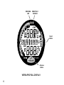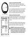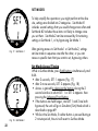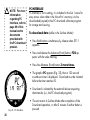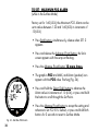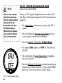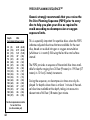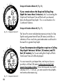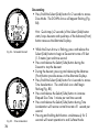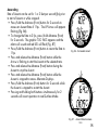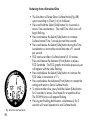
1
operating manual LIMITED TWO-YEAR WARRANTY For details, refer to the Product Warranty Registration Card provided. COPYRIGHT NOTICE This operating manual is copyrighted, all rights are reserved. It may not, in whole or in part, be copied, photocopied, reproduced, translated, or reduced to any electronic medium or machine readable form without prior consent in writing from Oceanic / 2002 Design. Versa Pro Operating Manual, Doc. No. 12-2283 © 2002 Design 2001 San Leandro, Ca. USA 94577 TRADEMARK NOTICE Oceanic, the Oceanic logo, Versa Pro, the Versa Pro logo, Smart Glo, and Oceanglo are all registered and unregistered trademarks of Oceanic. All rights are reserved. PATENT NOTICE U.S. Patents have been issued, or applied for, to protect the following design features: Dive Time Remaining (U.S. Patent no. 4,586,136), Data Sensing and Processing Device (U.S. Patent no. 4,882,678), and Variable Ascent Rate Indicator (U.S. Patent no. 5,156,055). User Setable Display (U.S. Patent no. 5,845,235) is owned by Suunto Oy (Finland). DECOMPRESSION MODEL The programs within the Versa Pro simulate the absorption of nitrogen into the body by using a mathematical model. This model is merely a way to apply a limited set of data to a large range of experiences. The Versa Pro dive computer model is based upon the latest research and experiments in decompression theory. Still, using the Versa Pro, just as using the U.S. Navy (or other) No Decompression Tables, is no guarantee of avoiding decompression sickness, i.e. “the bends.” Every diver’s physiology is different, and can even vary from day to day. No machine can predict how your body will react to a particular dive profile. 2 CONTENTS LIMITED TWO-YEAR WARRANTY ............................................................................................................................. 2 NOTICES ..................................................................................................................................................................... 2 DECOMPRESSION MODEL ....................................................................................................................................... 2 FEATURES AND DISPLAYS ............................................................................................. 7 INTERACTIVE CONTROL CONSOLE ........................................................................................................................ 8 BAR GRAPHS ............................................................................................................................................................. 9 Tissue Loading Bar Graph (TLBG) ......................................................................................................................... 9 Oxygen Bar Graph (O2BG) ................................................................................................................................... 10 Variable Ascent Rate Indicator (VARI) ................................................................................................................. 10 ALPHA / NUMERIC DISPLAYS ................................................................................................................................ 11 Depth Displays ..................................................................................................................................................... 11 Time and Date Displays ....................................................................................................................................... 12 Temperature Display ............................................................................................................................................. 13 AUDIBLE ALARM ...................................................................................................................................................... 13 LED Warning Light ............................................................................................................................................... 13 BACKLIGHT .............................................................................................................................................................. 15 POWER SUPPLY ...................................................................................................................................................... 15 Battery Indicator ................................................................................................................................................... 15 Low Battery Condition .......................................................................................................................................... 16 FO2 MODE ................................................................................................................................................................. 17 FO2 50% Default .................................................................................................................................................. 18 ACTIVATION AND SETUP ............................................................................................... 19 ACTIVATION .............................................................................................................................................................. 20 Backup Activation ................................................................................................................................................. 21 SURFACE MODE ...................................................................................................................................................... 21 SET MODES .............................................................................................................................................................. 22 ENTERING SETTINGS -SET MODE #1 ............................................................................................................... 23 ENTERING SETTINGS -SET MODE #2 ............................................................................................................... 27 3 CONTENTS (continued) PLAN AND DIVE MODES ................................................................................................ 41 PRE DIVE PLANNING SEQUENCETM ...................................................................................................................... 42 TISSUE LOADING BAR GRAPH .............................................................................................................................. 44 OXYGEN ACCUMULATION BAR GRAPH ............................................................................................................... 45 VARIABLE ASCENT RATE INDICATOR .................................................................................................................. 45 CONTROL OF DISPLAYS ......................................................................................................................................... 46 NO DECOMPRESSION DIVE MODE ....................................................................................................................... 46 DECOMPRESSION DIVE MODE ............................................................................................................................. 49 VIOLATION MODES .................................................................................................................................................. 52 Conditional Violation Mode .................................................................................................................................. 52 Delayed Violation Modes ..................................................................................................................................... 54 Immediate Violation Mode and Gauge Mode ...................................................................................................... 55 HIGH PO2 DIVE MODE ............................................................................................................................................. 57 HIGH OXYGEN ACCUMULATION ............................................................................................................................ 58 USER SET DIGITAL GAUGE MODE ........................................................................................................................ 59 UNEXPECTED LOSS OF DISPLAYED INFORMATION .......................................................................................... 59 RESET FEATURE ..................................................................................................................................................... 60 POST DIVE MODES ........................................................................................................ 61 POST DIVE SURFACE MODE .................................................................................................................................. 62 TRANSITION PERIOD .............................................................................................................................................. 62 AFTER THE TRANSITION PERIOD (THE FIRST 2 HOURS) .................................................................................. 64 To activate the Backlight - .................................................................................................................................... 64 To access the Pre Dive Planning Sequence - ...................................................................................................... 64 To access the Time to Fly Countdown ................................................................................................................. 65 To access the Time to Desaturate Countdown .................................................................................................... 65 Log Mode .............................................................................................................................................................. 66 AFTER THE FIRST 2 HOURS ................................................................................................................................... 68 WET CONTACTS ....................................................................................................................................................... 69 DOWNLOADING DATA TO A PC .............................................................................................................................. 70 4 CONTENTS (continued) SIMULATOR (DEMO) MODE .......................................................................................... 71 GENERAL ........................................................................................................................ 77 CARE AND CLEANING ............................................................................................................................................. 78 INSPECTIONS AND SERVICE ................................................................................................................................. 78 BATTERY REPLACEMENT ...................................................................................................................................... 80 ALTITUDE COMPENSATION .................................................................................................................................... 85 SPECIFICATIONS ..................................................................................................................................................... 86 OCEANIC WORLD WIDE .......................................................................................................................................... 91 SERVICE RECORD ................................................................................................................................................... 92 Pay special attention to items marked with this Warning symbol. WARNING: Prior to diving with the Versa Pro, you must also read and understand the Oceanic Dive Computer Safety and Reference Manual. 5 WARNING LED SMARTGLO SENSOR Select Button Advance Button VERSA PRO FULL DISPLAY 6 WARNING: Prior to diving with the Versa Pro, you must also read and understand the Oceanic Dive Computer Safety and Reference Manual which provides Important Warnings and Safety Recommendations as well as general product information. FEATURES and DISPLAYS 7 INTRODUCTION Welcome to Oceanic and thank you for choosing the Versa Pro ! It is extremely important that you read this Operating Manual in sequence and understand it completely before attempting to use the Versa Pro. It is equally important that you read the Oceanic Dive Computer Safety and Reference Manual provided with your Versa Pro. It contains information that you must become familiar with prior to diving with your Versa Pro. Remember that technology is no substitute for common sense, and a dive computer only provides the person using it with data, not the knowledge to use it. INTERACTIVE CONTROL CONSOLE b The Front button is referred to as Advance (Fig. 1a) and the Side button as Select (Fig. 1b). a Fig. 1 - Interactive Control 8 The Interactive Control Console consists of two Control Buttons which allow you to select display options and access specific information when you want to see it. They are also used to enter settings, activate the Backlight, and acknowledge the Audible Alarm. BAR GRAPHS Tissue Loading Bar Graph (TLBG) The Tissue Loading Bar Graph (Fig. 2a) represents tissue loading of nitrogen, showing your relative no decompression or decompression status. As your depth and elapsed dive time increase, segments will add to the Graph, and as you ascend to shallower depths, the Bar Graph will begin to recede, indicating that additional no decompression time is allowed for multilevel diving. The Tissue Loading Bar Graph monitors 12 different nitrogen compartments simultaneously and displays the one that is in control of your dive. It is divided into a green No Decompression (normal) zone, a yellow Caution zone (also No Decompression), and a red Decompression (danger) zone. While you cannot provide a guarantee against the occurrence of decompression sickness, you may choose your own personal zone of caution based upon age, physique, excessive weight, etc., to reduce the statistical risk. NOTE: Displays associated with oxygen and the O2 Bar Graph will only appear if FO2 has been set at a value other than 'Air' (e.g., a numerical value). a Fig. 2 - TLBG 9 a b Fig. 3 - O2BG and VARI Deeper than 60 feet (18 m) Segments Ascent Rate = Displayed FPM MPM 0 0-20 0-6 1 21-30 6.5-9 2 31-40 9.5-12 3 41-50 12.5-15 4 51-60 15.5-18 5 >60 >18 60 feet (18 m) & Shallower Segments Ascent Rate = Displayed FPM MPM 0 0-10 0-3 1 11-15 3.5-4.5 2 16-20 5-6 3 21-25 6.5-7.5 4 26-30 8-9 5 >30 >9 Variable Ascent Rate Indicator 10 Oxygen Accumulation Bar Graph (O2BG) The O2 Bar Graph (Fig. 3a) represents oxygen loading, showing the maximum of either per dive accumulated oxygen, or 24 hour period accumulated oxygen. As your oxygen exposure (accumulation) increases during the dive, segments will add to the Bar Graph, and as loading decreases, it will begin to recede, indicating that additional exposure is allowed for that dive and 24 hour period. Variable Ascent Rate Indicator (VARI) The Variable Ascent Rate Indicator (Fig. 3b) provides a visual representation of ascent speed (i.e., an ascent speedometer). Green is a 'normal' rate, yellow a 'caution' rate, and red is 'Too Fast'. The segments of the Variable Ascent Rate Indicator represent two sets of speeds which change at a reference depth of 60 feet (18 meters). Refer to the chart for segment values. WARNING: At depths greater than 60 feet (18 meters), ascent rates should not exceed 60 feet per minute (18 meters per minute). At depths of 60 feet (18 meters) and shallower, ascent rates should not exceed 30 feet per minute (9 meters per minute). ALPHA / NUMERIC DISPLAYS Each numeric and graphic display represents a unique piece of information. It is imperative that you understand the formats, ranges, and values of the information represented to avoid any possible misunderstanding that could result in error. Depth Displays During a dive, the Current Depth display (Fig. 4a), indicates depths from 0 to 330 feet (99.9 meters) in 1 foot (.1 meter) increments. By pressing the Advance (Front) button, the Maximum Depth reached during that dive will be displayed in the center/left portion of the display (Fig. 4b). • When the unit is set to operate as a digital depth gauge/ timer (referred to as User Set Gauge Mode), the Depth Display range is 'extended' to 399 feet (120 meters). At depths greater than 99.9 meters it will indicate metric values in increments of 1 meter. During a Decompression Dive, the required Ceiling Stop Depth is displayed in the center of the screen. Maximum Depth can be viewed by pressing the Advance (Front) button. a b Fig. 4 - Depth Displays 11 b a Fig. 5 - Time Displays Time and Date Displays Time displays are shown in hour:minute format (i.e., 1:16 represents 1 hour and 16 minutes, not 116 minutes!). The colon that separates hours and minutes blinks once per second when the display is indicating real time (e.g., Elapsed Dive Time), and is solid (non-blinking) when times are calculated projections (e.g., Time to Fly). The Main Time display is located in the lower portion of the display (Fig. 5a) and a second time display (Fig. 5b) is located in the center/right. Both displays are identified by a clock icon. • Time of Day can be set for 12 hour format (Am/Pm) or 24 hour format. a Date is displayed in the center/left portion of the screen (Fig. 6a) only to identify dive data while it is viewed in the Log Mode. • When Units of Measure are set for 'Imperial', the Month appears to the left of Day. When set for Metric, the Month appears to the right of Day. Fig. 6 - Date Display 12 Temperature Display Ambient Temperature is displayed in the center/left portion of the screen (Fig. 7a) while in the Surface Mode and Log Mode, and can be viewed as part of an Alternate Display when the Advance (Front) button is pressed while in a dive mode. If the Temperature exceeds a value of '99', two dashes ( - - ) will be displayed on the screen until the unit's temperature decreases to '99'. NOTE: The Informational Displays are described in detail as the various operating modes they appear in are presented throughout this manual. AUDIBLE ALARM LED Warning Light A red LED Warning Light and Speaker icon are synchronized with the Audible Alarm and will illuminate the display when the Alarm emits a tone. They will turn OFF when the Alarm is acknowledged, or Set OFF (a user setting). When warning situations activate the Alarm, the unit will emit a continuous tone for 30 seconds, or until the situation is corrected, or it is acknowledged by pressing the Advance (Front) button for 2 seconds. If acknowledged by the user and the situation corrected, the Alarm will sound again upon reentry into the warning situation, or entry into another type of warning situation. a Fig. 7 - Temperature Display 13 Situations that will sound the Alarm, if it is turned ON (a user setting), include • Entry into Decompression Mode • PO2 => than the Max PO2 Alarm (a user setting), or => 1.60 ATA. • Descent deeper than the Max Depth Alarm (a user setting). • Nitrogen Bar Graph Alarm (a user setting). • Dive Time Remaining Alarm (a use setting). • Elapsed Dive Time Alarm (a use setting). • O2 Accumulation => allowable per dive limit, or limit for a 24 hour period. • Ascending above a required Decompression stop depth for less than 5 minutes (Conditional Violation). • Ascent rate exceeds 60 feet/minute (18 meters/minute) if greater than 60 feet (18 meters), or 30 feet/minute (9 meters/minute) at 60 feet (18 meters) and shallower. During the following situations, the 30 second continuous tone will be followed by a 5 second steady beep that will not turn off when acknowledged, even if it was user Set OFF • Ascending above a required Decompression stop depth for more than 5 minutes (Delayed Violation). • Decompression requires a ceiling stop depth of 70 feet/21 meters or deeper. • Being on the surface for 5 minutes after a Conditional Violation (Permanent Violation). A single short beep (which cannot be disabled) is emitted for the following • After the Diagnostic countdown, if everything is okay. • If the unit automatically returns to Surface Mode from Simulator Mode. • Upon completion of a Hot Swap battery change with calculations saved. • Change from Delayed to Full Violation 5 minutes after the dive. 14 BACKLIGHT To activate the Backlight - press the Select (Side) button. • On the surface, the Smart Glo® feature senses the intensity of natural light present. If a low level of light is present, the Backlight will activate and illuminate the display for 5 seconds, or the Duration time (a user setting). • During a dive, the Oceanglo® feature will activate the Backlight and the display will be illuminated for 5 seconds, or the Duration time set (a user setting). • The Backlight does not operate during a Low Battery condition. • Press the button again to activate as desired. POWER SUPPLY The Versa Pro utilizes one (1) type CR 2450 Lithium 3 volt cell that should provide 300 hours of continuous, or 50 activation periods, of operation. If you conduct 1 dive each time the unit is activated, you should obtain approximately 50 dives. If you conduct 3 dives each time the unit is activated, you should obtain approximately 150 dives. Battery Indicator A Battery Indicator provides an indication of battery condition. When power is sufficient for normal unit operation, the Indicator will be displayed during Surface Mode (Fig. 8a). The Indicator will not be displayed during Dive Mode(s). a Fig. 8 - Battery Indicator 15 Low Battery Condition Voltage level is checked upon activation and every 10 minutes during operation. • When the unit estimates that 75 % of the Rated Power has been consumed, the lower bar of the Battery Indicator (only segment) will be displayed, and the outline of the Indicator will flash once per second as a warning that the battery is to be replaced prior to conducting any further dives. • Upon decreasing to a voltage level that will no longer sustain proper operation, the Indicator will flash 5 times followed by shutdown of the unit. • If a Low Battery Condition exists when the unit is activated (by pressing the button), the graphic bAT and the Battery Indicator will appear flashing for 5 seconds (Fig. 9) followed by shutdown of the unit. • If the button is not pressed to activate the unit prior to a dive, and a Low Battery Condition exists, the Battery Indicator will appear flashing as a warning upon descent past 4 feet (1.2 meters). No other information will be displayed. • If the unit did not display a Low Battery Condition 'prior to' entering the Dive Mode, and a Low Battery Condition occurs during the dive, there will be sufficient battery power to maintain unit operation for the remainder of 'that dive'. The Battery Indicator will appear after the dive in Surface Mode. Fig. 9 -Low Battery Condition 16 When the Battery is removed, settings and nitrogen and oxygen calculations for repetitive dives will be retained, if a new battery can be inserted within 8 seconds. Otherwise the calculations will reset to zero and settings such as Time, Date, and FO2 must be reset. FO2 MODE After Activation, the Versa Pro will operate as an Air computer without displaying information associated with oxygen calculations, unless it is set for a percentage of oxygen (FO2) other than Air (a numerical value between 21 and 50 %). When set with an FO2 value of 'Air' (Fig. 10), the Versa Pro will perform calculations the same as if FO2 were set for 21% oxygen, internally accounting for oxygen loading for any subsequent Nitrox dives. However, oxygen related displays, warnings, and the O2 Bar Graph will not appear on the display for that dive, or subsequent dives, unless FO2 is set for a numerical value (21 - 50). Fig. 10 - FO2 set for Air Once a dive is made with the unit set as a nitrox computer (FO2 set for a numerical value), it cannot be programmed to operate as an 'Air' computer until 24 hours after the last dive. 'Air' will not be displayed as an option in the FO2 Mode. However, you can set FO2 for 21% for use with Air. When FO2 is set at a value of 21% (Fig. 11), the unit will remain set at 21% for subsequent nitrox dives until FO2 is set to a higher value, or until it automatically turns off and is reactivated. Setting FO2 is described on Page 23. Fig. 11 - FO2 set for 21% 17 FO2 50% Default If the Default is set to ON (Fig. 12) and FO2 is set to a value 'greater than 21%', the FO2 set point value will automatically revert to 50% 10 minutes after that dive. The Maximum Depth that can be achieved with a PO2 of 1.60 ATA will also be displayed. Fig. 12 - FO2 Default ON • FO2 must therefore be reset for each repetitive nitrox dive, or the value will automatically 'default' to 50(%) and the dives will be calculated based on 50% O2 (50% nitrogen) for oxygen calculations and 21% O2 (79% nitrogen) for nitrogen calculations. 18 DI RESP O Fig. 13 - FO2 Default OFF VER If the Default is set to OFF (Fig. 13), the FO2 value for repetitive dives remains the same as previously set until the set point is manually changed. N SI LE B WARNING: Prior to diving with the Versa Pro, you must also read and understand the Oceanic Dive Computer Safety and Reference Manual which provides Important Warnings and Safety Recommendations as well as general product information. ACTIVATION and SETUP 19 ACTIVATION WARNING: If the unit is activated at elevations higher than 14,000 feet (4,267 meters), it will perform a diagnostic check and immediately shutdown. To Activate the Versa Pro press and release the Advance (Front) Button. Fig. 14 - Diagnostic Mode Fig. 15 - Serial Number 20 • Upon manual activation, the unit will enter Diagnostic Mode (Fig. 14), displaying all segments of the LCD as 8's, followed by dashes (- -), then a countdown from 9 to 0. Diagnostic Mode checks the display and battery voltage to ensure that everything is within tolerance and functioning properly. • When the front (Advance) button is held depressed when the Diagnostic countdown reaches 00, an External Access request is initiated. A Serial Number screen appears displaying the unit’s Serial Number and firmware code Revision Number as long as the button is held depressed (Fig. 15). Upon releasing the button, the unit shuts Off. • After manual activation, it will also check the ambient barometric pressure, and calibrate its present depth as zero. At elevations of 2,000 feet (610 meters) or higher, it will recalibrate itself to measure depth in feet of fresh water instead of feet of sea water. Backup Activation (only if Water Activation is set ON) As a backup, the Versa Pro will also automatically activate by water contact. This is accomplished by bridging the gap between contacts located on the Button stems and back of the case. The graphic H2O that will be displayed as an indication is described later. If no dive is made within 2 hours after initial activation, the unit will automatically deactivate. If the wet contacts are still bridged, the unit will reactivate and display the H2O graphic. Fig. 16A- Surface Mode SURFACE MODE Surface Mode (Fig. 16A), identified by the Surface Time icon, follows Diagnostic Mode after Activation. Information includes Dive Number '0' (no dive made yet), Temperature (and icon), Time of Day (with icon), the Battery Consumption Indicator, and Surface Time (with flashing colon). If the wet contacts are bridged, the graphic 'H2O' will appear in place of the dive number '0' (Fig. 16B). After the unit is rinsed and dried, '0' will replace 'H2O'. • Press the Advance (Front) button to access a sequence that includes Plan, Fly, DeSaturate, and Log Modes. • Press the Select (Side) button momentarily (less than 2 seconds) to activate the Backlight. Fig. 16B - Surface Mode (rinse and dry the unit) 21 SET MODES To help simplify the operations you might perform at the dive site, settings are divided into 2 categories. Set Mode #1 includes several settings that you would change more often and Set Mode #2 includes those items not likely to change once you set them. Set Mode 2 can be accessed by first entering settings in Set Mode 1, or by bypassing Set Mode 1. Fig. 17 - Set Mode 1 Fig. 18 - Set Mode 2 22 After gaining access to Set Mode 1 or Set Mode 2, settings can be made in sequence one after the other, or you can access a specific item that you want to set, bypassing others. Set Mode Access/Timing While in Surface Mode, press Both buttons simultaneously and hold • after 2 seconds, SET: 1 appears (Fig. 17) • after 2 more seconds, SET: 2 appears (Fig. 18) • Access is gained by releasing the buttons during the 2 second window in which SET: 1 or SET: 2 appears. then pressing the Advance (Front) button. • If the buttons are held longer, and SET 1 and 2 are both bypassed, the unit will go to Simulator (Sim) Mode which is described on page 69. • While in the Set Mode, if neither button is pressed during a 2 minute period, the unit will revert to Surface Mode. ENTERING SETTINGS -SET MODE #1 TO SET - FO2 (while in the Surface Mode) Factory set for Air, FO2 can also be set to values between 21 and 50% in increments of 1%. • Press Both buttons simultaneously, release when SET: 1 appears. • Press and release the Advance (Front) button, FO2 appears with the value flashing (Fig. 19). Fig. 19 - Set FO2 • Press and release the Side (Select) button repeatedly to increase the FO2 value from 21 to 50% in increments of 1%, then display AIR again; - or - Press and hold the Side (Select) button to scroll from AIR to 32%, then press and hold again to scroll from 32 to 50%, then AIR. • For each FO2 value that appears, the display indicates the Maximum Depth that can be achieved for a PO2 of 1.60 ATA (Fig. 20), or the setting selected by the user. If FO2 is set for Air, no value is displayed. • Press the Advance (Front) button to accept the setting and advance to Set Depth Alarm, or press and hold Both buttons for 2 seconds to revert to Surface Mode. Fig. 20 - FO2 set for 32% 23 TO SET - MAX DEPTH ALARM (while in the Surface Mode) Factory set for 330 feet, the Alarm can be set to values between 30 feet (3 meters) and 330 feet ( 99 meters) in increments of 10 foot (3 meters). • Press Both buttons simultaneously, release when SET: 1 appears. • Press and release the Advance (Front) button, FO2 appears with the value flashing. • Press the Advance (Front) button 1 more time. • The graphics FEET MAX and dEEP, and Alarm icon appear with the Max Depth value flashing (Fig. 21). • Press and release the Select (Side) button until the desired Depth Alarm value appears, or press and hold the button to scroll through the Set Points. • Press the Advance (Front) button to accept the setting and advance to Elapsed Dive Time Alarm, or press and hold Both buttons for 2 seconds to revert to Surface Mode. Fig. 21 - Set Max Depth Alarm 24 TO SET - ELAPSED DIVE TIME ALARM (while in the Surface Mode) Factory set for 0:00 hr:min, the Alarm can be set to values between 0:10 and 3:00 hr:min in increments of 0:05 hr:min. • Press Both buttons simultaneously, release when SET: 1 appears. • Press and release the Advance (Front) button, FO2 appears with the value flashing. • Press the Advance (Front) button 2 more times. • The graphic EdT, and Alarm and Dive Time icons appear with the Elapsed Dive Time value flashing (Fig. 22). • Press and release the Select (Side) button until the desired Alarm value appears, or press and hold the button to scroll through the Set Points. • Press the Advance (Front) button to accept the setting and advance to PC Interface, or press and hold Both buttons for 2 seconds to revert to Surface Mode. Fig. 22 - Set Elapsed Dive Time Alarm 25 NOTE: For more information regarding PC Interface, refer to page 69 of this manual and to documents provided with the PC download product. PC INTERFACE PC Interface is not a setting, it is included in the Set 1 menu for easy access when data in the Versa Pro's memory is to be downloaded (copied) to the PC download software program for storage and viewing. To download data (while in the Surface Mode)• Press Both buttons simultaneously, release when SET: 1 appears. • Press and release the Advance (Front) button, FO2 appears with the value flashing. • Press the Advance (Front) button 3 more times. • The graphic PC appears (Fig. 23), then a 120 second countdown timer is displayed. Download must be initiated before the timer reaches 00. • Download is initiated by the external device requesting data transfer (i.e., the PC download program). Fig. 23 - PC Interface 26 • The unit reverts to Surface Mode after completion of the Download operation, or after 2 minutes if neither button is pressed. ENTERING SETTINGS -SET MODE #2 These settings are ones that are not likely to change. To save time at the dive site, verify the set points and adjust them as desired prior to departing on the day's dive trip. TO SET - UNITS OF MEASURE (while in the Surface Mode) To return to Surface Mode at any time while in Set Mode, press and hold Both buttons for 2 seconds. Factory set for Imperial, Units of Measure can also be set for Metric. • Press Both buttons simultaneously, release when SET: 2 appears. • Press and release the Advance (Front) button, the Units screen appears with the graphic FT (or M), and Temperature icon and letter F (or C) flashing (Fig. 24). • Press the Select (Side) button to toggle between Imperial (F and Feet) and Metric (M and C) units. • Press the Advance (Front) button to accept the setting and advance to Set Hour Format, or press and hold Both buttons for 2 seconds to revert to Surface Mode. Fig. 24- Set Units of Measure 27 TO SET - HOUR FORMAT (while in the Surface Mode) Factory set for 12 Hr (12: Am to 11: Pm), the Format can also be set for 24 Hr (0: to 23: hours). • Press Both buttons simultaneously, release when SET: 2 appears. • Press and release the Advance (Front) button, the Units screen appears with the set point flashing. • Press the Advance (Front) button 1 more time. • The graphic Hour appears with 12 (or 24) flashing (Fig. 25). • Press and release the Select (Side) button to toggle between 12 and 24. • Press the Advance (Front) button to accept the setting and advance to Set Hour, or press and hold Both buttons for 2 seconds to revert to Surface Mode. Fig. 25 - Set Hour Format 28 TO SET - TIME (while in the Surface Mode) Set for factory local time, the Time can be set to values between 0:00 and 12:59 (Am/Pm) or 0:00 and 23:59. • Press Both buttons simultaneously, release when SET: 2 appears. • Press and release the Advance (Front) button, the Units screen appears with the set point flashing. • Press the Advance (Front) button 2 more times. Time appears with the Hour value flashing (Fig. 26). Fig. 26 - Set Hour • Press and release the Select (Side) button to advance the Hour value in increments of one hour, or press and hold the button to scroll through the Set Points. • Press the Advance (Front) button to accept the setting. The Minute value flashes (Fig. 27). • Press and release the Select (Side) button to advance the Minute value in increments of one minute, or press and hold the button to scroll through the Set Points. • Press the Advance (Front) button to accept the setting and advance to Set Year. Fig. 27 - Set Minute 29 TO SET - DATE (after setting Time) Factory set for the factory local Date, the Date can be set to values between 01/01/01 and 12/31/20. • After having set and accepted the Time, the Date appears with the graphic dAY, and Year value flashing (Fig. 28). Fig. 28 - Set Year • Press and release the Select (Side) button to advance the Year value in increments of one year, or press and hold the button to scroll through the Set Points. • Press the Advance (Front) button to accept the setting. The Month value flashes (Fig. 29). • Press and release the Select (Side) button to advance the Month value in increments of one month, or press and hold the button to scroll through the Set Points. Fig. 29 - Set Month • Press the Advance (Front) button to accept the setting. The Day value flashes (Fig. 30). • Press and release the Select (Side) button to advance the Day value in increments of one day, or press and hold the button to scroll through the Set Points. Fig. 30 - Set Day 30 • Press the Advance (Front) button to accept the setting. TO SET - AUDIBLE ALARM (while in the Surface Mode) Factory set for ON, the Alarm can be also be set to OFF. This setting also applies to the LED Warning Indicator that is synchronized with the Audible Alarm. When set OFF, the Alarm will not sound during the conditions described on page 14. • Press Both buttons simultaneously, release when SET: 2 appears. • Press and release the Advance (Front) button, the Units screen appears with the set point flashing. • Press the Advance (Front) button 7 more times. • The graphic ALM and Alarm (speaker) icon appear with ON (or OFF) flashing (Fig. 31). • Press and release the Select (Side) button to toggle between ON and OFF. • Press the Advance (Front) button to accept the setting and advance to Set Max TLBG Alarm, or press and hold Both buttons for 2 seconds to revert to Surface Mode. Fig. 31- Set Audible Alarm 31 TO SET - MAXIMUM TISSUE LOADING BAR GRAPH (TLBG) ALARM (while in the Surface Mode) Factory set for DECO (all 8 segments), the Maximum Tissue Loading Bar Graph (TLBG) Alarm can be set to values between DECO (all 8 segments) and 1 segment. • Press Both buttons simultaneously, release when SET: 2 appears. • Press and release the Advance (Front) button, the Units screen appears with the set point flashing. • Press the Advance (Front) button 8 more times. • The graphic ndc and Alarm (speaker) icon appear with the full TLBG flashing (Fig. 32). • Press and release the Select (Side) button to decrease the number of segments one at a time, or press and hold the button to scroll through the Set Points. • Press the Advance (Front) button to accept the setting and advance to Set Dive Time Remaining Alarm, or press and hold Both buttons for 2 seconds to revert to Surface Mode. Fig. 32 - Set Max TLBG Alarm 32 TO SET - DIVE TIME REMAINING ALARM (while in the Surface Mode) Factory set for 0:00 (minutes), the Dive Time Remaining Alarm can be set to values between 0:00 and 0:20 (minutes) in increments of 1 minute. • Press Both buttons simultaneously, release when SET: 2 appears. • Press and release the Advance (Front) button, the Units screen appears with the set point flashing. • Press the Advance (Front) button 9 more times. • The graphic dtr, and Alarm (speaker) and Dive Mode icons appear with the Dive Time Remaining value flashing (Fig. 33). • Press and release the Select (Side) button to advance the Alarm value in increments of one minute, or press and hold the button to scroll through the Set Points. • Press the Advance (Front) button to accept the setting and advance to Set Max PO2 Alarm, or press and hold Both buttons for 2 seconds to revert to Surface Mode. Fig. 33 - Set Dive Time Remaining Alarm 33 TO SET - MAXIMUM PO2 ALARM (while in the Surface Mode) Factory set for 1.60 (ATA), the Maximum PO2 Alarm can be set to values between 1.20 and 1.60 (ATA) in increments of .10 (ATA). • Press Both buttons simultaneously, release when SET: 2 appears. • Press and release the Advance (Front) button, the Units screen appears with the set point flashing. • Press the Advance (Front) button 10 more times. • The graphics PO2 and MAX, and Alarm (speaker) icon appear with the PO2 value flashing (Fig. 34). • Press and hold the Select (Side) button to advance the Alarm value in increments of .10 (ATA), or press and hold the button to scroll through the Set Points. • Press the Advance (Front) button to accept the setting and advance to Set FO2 50% Default, or press and hold Both buttons for 2 seconds to revert to Surface Mode. Fig. 34 - Set Max PO2 Alarm 34 TO SET - FO2 50% DEFAULT (while in the Surface Mode) Factory set ON, the FO2 50% Default feature can be set to OFF. The effects of this feature being ON or OFF are described on page 17. • Press Both buttons simultaneously, release when SET: 2 appears. • Press and release the Advance (Front) button, the Units screen appears with the set point flashing. • Press the Advance (Front) button 11 more times. • The graphics FO2 and 50 appear with ON (or OFF) flashing (Fig. 35). • Press and release the Select (Side) button to toggle between ON and OFF. • Press the Advance (Front) button to accept the setting and advance to Set Backlight Duration, or press and hold Both buttons for 2 seconds to revert to Surface Mode. Fig. 35 - Set FO2 50% Default 35 TO SET - BACKLIGHT DURATION (while in the Surface Mode) Factory set for 7 (seconds), the Backlight Duration can be set to values of 0, 3, or 7 (seconds). • Press Both buttons simultaneously, release when SET: 2 appears. • Press and release the Advance (Front) button, the Units screen appears with the set point flashing. • Press the Advance (Front) button 12 more times. • The graphic GLO and Time icon appear with the Duration value flashing (Fig. 36). • Press and release the Select (Side) button to advance the Duration from :00 to :03 to :07 (seconds). • Press the Advance (Front) button to accept the setting and advance to Set Sampling Rate, or press and hold Both buttons for 2 seconds to revert to Surface Mode. Fig. 36 - Set Backlight Duration 36 TO SET - PC SAMPLING RATE (while in the Surface Mode) Factory set for 30 (seconds), the Sampling Rate can be set to values of 2, 15, 30, or 60 seconds, or 2, 5, or 10 feet (.5, 1.5, or 3 meters). • Press Both buttons simultaneously, release when SET: 2 appears. • Press and release the Advance (Front) button, the Units screen appears with the set point flashing. • Press the Advance (Front) button 13 more times. NOTE: Sampling Rate is the interval at which data samples are recorded during a dive for subsequent download to the PC program. This setting has no effect on displayed data or data in the unit's viewable Log. • The graphics SR and SECS appear with the Sampling Rate value flashing (Fig. 37). • Press and release the Select (Side) button to advance the Rate one selection at a time, or press and hold the button to scroll through the Set Points. • Press the Advance (Front) button to accept the setting and advance to Set Digital Gauge Mode, or press and hold Both buttons for 2 seconds to revert to Surface Mode. Fig. 37 - Set Sampling Rate 37 NOTE: Once a dive is made with this feature set ON, the setting will be locked ON for 24 hours after the dive. Set Digital Gauge Mode will not appear as a selection during that 24 hour period. TO SET - USER SET DIGITAL GAUGE MODE (while in the Surface Mode) Factory set OFF, Digital Gauge Mode can also be set ON. The effects of this feature being ON or OFF are described on page 58. • Press Both buttons simultaneously, release when SET: 2 appears. • Press and release the Advance (Front) button, the Units screen appears with the set point flashing. • Press the Advance (Front) button 14 more times. • The graphic GAU appears with OFF (or ON) flashing (Fig. 38). • Press and release the Select (Side) button to toggle between ON and OFF. • Press the Advance (Front) button to accept the setting and advance to Set Water Activation, or press and hold Both buttons for 2 seconds to revert to Surface Mode. Fig. 38 - Set Digital Gauge Mode 38 TO SET - WATER ACTIVATION (while in the Surface Mode) Factory set for ON, the Water Activation feature can also be set for OFF (disabled) to prevent inadvertent activation during travel or storage. When set ON, the Versa Pro will automatically Activate and enter Dive Mode upon immersion in water. • Press Both buttons simultaneously, release when SET: 2 appears. WARNING: If this feature is set for OFF, the Versa Pro must be manually activated prior to commencing a dive. • Press and release the Advance (Front) button, the Units screen appears with the set point flashing. • Press the Advance (Front) button 15 more times (14 more times after a dive in Digital Gauge Mode). • The graphics ACT and H20 appear with ON (or OFF) flashing (Fig. 39). • Press and release the Select (Side) button to toggle between ON and OFF. • Press the Advance (Front) button to accept the setting and revert to Surface Mode. Fig. 39 - Set Water Activation 39 t u n o m p b m q l c k j d i h g r a s f e LCD DISPLAY 40 Components: a. O2 (oxygen) Bar Graph b. Tissue Loading Bar Graph c. Variable Ascent Rate Indicator d. Select (side) Button e. Advance (front) Button f. Battery Indicator g. Graphic - Maximum Depth h. Icon - Ascend Arrow i. Icon - Decompression Ceiling j. Icon - Descend Arrow k. Icon - Temperature l. Icon - Alarm m. Icon - Log Mode n. Graphic - Demo Mode o. Graphic - Depth p Graphic - Ascent Too Fast q. Icon - Time r. Icon - Operating Mode s. Icon - O2 (oxygen) t. LED Warning Light u. Smartglo Sensing Port WARNING: Prior to diving with the Versa Pro, you must also read and understand the Oceanic Dive Computer Safety and Reference Manual which provides Important Warnings and Safety Recommendations as well as general product information. PLAN and DIVE MODES 41 PRE DIVE PLANNING SEQUENCETM Oceanic strongly recommends that you review the Pre Dive Planning Sequence (PDPS) prior to every dive to help you plan your dive as required to avoid exceeding no decompression or oxygen exposure limits. Depth NDL feet (meters) hours:mins 30 40 50 60 70 80 90 100 110 120 130 140 150 160 170 180 190 (9) (12) (15) (18) (21) (24) (27) (30) (33) (36) (39) (42) (45) (48) (51) (54) (57) 4:20 2:17 1:21 :57 :40 :30 :24 :19 :16 :13 :11 :09 :08 :07 :07 :06 :05 (4:43) (2:24) (1:25) (:59) (:41) (:32) (:25) (:20) (:17) (:14) (:11) (:09) (:08) (:07) (:06) (:06) (:05) No Decompression Limits for an Air Dive (no dive made yet) 42 This is especially important for repetitive dives when the PDPS indicates adjusted dive times that are available for the next dive, based on residual nitrogen or oxygen accumulation (whichever is in control) following the last dive and surface interval. The PDPS provides a sequence of theoretical dive times available for depths ranging from 30 feet (9 meters) to 190 feet (57 meters) in 10 foot (3 meter) increments. During the sequence, no decompression times are only displayed for depths where there is at least 1 minute of theoretical dive time available at the depth, taking into account a descent rate of 60 feet (18 meters) per minute. To access the Pre Dive Planning Sequence (while in the Surface mode) • Press the Advance (Front) button 1 time • Press and release the Select (Side) button to advance through the depths/times, one screen at a time. • Press the Advance (Front) button to access Fly Mode. • The unit will revert to Surface Mode after 2 minutes if no button is pressed. • With each depth displayed by the Pre Dive Planning Sequence, you will see either predicted no decompression limits (NDLs) based upon your previous dive profiles (if calculated to be nitrogen controlled), or predicted oxygen tolerance limits (OTLs) based upon either a single dive exposure or your 24 hour accumulation of oxygen (if calculated to be oxygen controlled). • The Maximum Depth allowed for PO2 of 1.6 (ATA) for the FO2 setting will also be displayed. • Depths greater than the maximum depth that can be achieved with a PO2 of 1.60 ATA will not be displayed. • If the Tissue Loading Bar Graph is displayed (Fig. 40), that next dive is calculated to be controlled by nitrogen loading. • If the O2BG and O2 symbol are displayed (Fig. 41), it is calculated to be controlled by oxygen loading. Fig. 40 - Nitrogen Control Fig. 41 - Oxygen Control 43 NOTE: The Versa Pro will store oxygen accumulation calculations for up to 10 dives conducted during a 24 hour period. If the maximum limit for oxygen loading has been exceeded for that day (24 hour period), all of the segments of the O2 bar graph will be displayed flashing . Depth/Time values will not appear until the O2 bar graph recedes into the green (normal) zone (i.e., your daily oxygen dosage decreases an amount equivalent to the amount accumulated during the latest dive completed). a TISSUE LOADING BAR GRAPH (Fig. 42a) As your Depth and Elapsed Dive Time increase, the Tissue Loading Bar Graph (TLBG) will add segments (green toward red) to represent the absorption of nitrogen. While ascending to shallower depths, the number of segments displayed will begin to recede, offering a graphic representation of your multilevel diving capability. Fig. 42 - Tissue Loading Bar Graph 44 OXYGEN ACCUMULATION BAR GRAPH (Fig. 43a) If FO2 was set for a numerical value (nitrox), the Oxygen Accumulation (O2) Bar Graph will add segments (green toward red) to represent oxygen accumulation for that dive, or 24 hour period, whichever amount is greater. VARIABLE ASCENT RATE INDICATOR (Fig. 44a) The Variable Ascent Rate Indicator (VARI) shows how fast you are ascending. When you exceed the maximum recommended ascent rate for the depth you are at (see below), it will enter the red (Too Fast) zone and you will be alerted by the graphic TOO FAST, all segments of the bar graph flashing, an Audible alarm and the red LED Warning Indicator (unless set OFF). The warnings will stop when your ascent rate is slowed. a Fig. 43 - O2 Bar Graph a • At depths greater than 60 feet (18 meters), maximum recommended rate is 60 feet/minute (18 meters/minute). • At depths of 60 feet (18 meters) and shallower, maximum recommended rate is 30 feet/minute (9 meters/minute). NOTE: Refer to page 10 for additional information pertaining to the Variable Ascent Rate Indicator. Fig. 44 - Ascent Alarm 45 CONTROL OF DISPLAYS During No Decompression conditions, various displays of information (up to 4) are available. Each provides Depth, Dive Time Remaining, and additional information. The intent of this feature is to provide the diver control of how much information is on display at any given time during the dive. The diver can change from one display to another as often as desired by pressing the Advance (Front) button, otherwise it does not change. During conditions in which cautionary type information is displayed (e.g., Decompression, High PO2, etc.), there is a Main Display of important information relevant to the specific condition. The diver can access another display, but it will automatically revert to the Main Display after 3 seconds. To activate the Backlight, during a dive press the Select (Side) button. • The displays will be illuminated as long as the button is depressed, plus it will remain illuminated for the Backlight Duration time that has been set (0, 3, or 7 seconds). • The Backlight will not activate during a Low Battery condition. NO DECOMPRESSION DIVE MODE The Versa Pro will enter the No Decompression Dive Mode when you descend deeper than 4 feet (1.2 meters). 46 No Decompression Dive Mode - Display #1 (Fig. 45) Information includes Current Depth, Dive Time Remaining (and Mode icon), and the applicable bar graphs. • Press and release the Advance (Front) button to view Display #2. No Decompression Dive Mode - Display #2 (Fig. 46) Fig. 45 - No Deco #1 Information includes Current Depth, Maximum Depth for that dive (and icon), Elapsed Dive Time (and icon), Dive Time Remaining (and Mode icon), and the applicable bar graphs. • Press and release the Advance (Front) button again to view Display #3. No Decompression Dive Mode - Display #3 (Fig. 47) Fig. 46 - No Deco #2 Information includes Current Depth, Temperature, Time of Day, Dive Time Remaining (and Mode icon), and the applicable bar graphs. • Press and release the Advance (Front) button again to view Display #4 (only if FO2 is set for a numerical value Nitrox), or revert to Display #1 (if FO2 is set for Air). Fig. 47 - No Deco #3 47 No Decompression Dive Mode - Display #4 (Fig. 48) Information includes - Current Depth, current value of PO2 (if a nitrox dive) and PO2 graphic, Dive Time Remaining (and Mode icon), and applicable bar graphs. • press the Advance (Front) button to view Display #1. No Decompression Dive Mode - SAFETY STOP (Fig. 49) Fig. 48 - No Deco #4 Upon ascending to 20 feet (6 meters) on any No Decompression dive in which Depth exceeded 30 feet (9 meters), a short beep will sound and a Safety Stop screen will appear displaying a Stop at 15 feet (4.5 meters) with a 3 minute countdown timer that counts down from 3:00 to :00 (min:sec). The Safety Stop will be displayed until the countdown times out, or the a descent is made below 30 feet (10 meters), or the diver surfaces. There is no Penalty if the diver surfaces prior to completing the Safety Stop. Information includes Current Depth, Stop Depth (15 feet or 4.5 meters), Stop Bar icon, Countdown Timer, Dive Time Remaining, and applicable bar graphs. Fig. 49 - No Deco Safety Stop 48 DECOMPRESSION DIVE MODE The Versa Pro is designed to help you by providing a representation of how close you are to entering decompression. Decompression Dive Mode (Fig. 50) activates when theoretical No Decompression time/depth limits are exceeded. Upon entering Decompression Mode, the Audible Alarm will sound and the red LED Warning Indicator (and icon) will flash for 30 seconds (unless set OFF), or until acknowledged. • Press and hold the Advance (Front) button for 2 seconds to acknowledge/silence the Audible Alarm (unless set OFF). • The UP Arrow and Deco Bar will flash if you are greater than 10 feet (3 m) deeper than the Required Stop Depth. • Once you are within 10 feet (3 m) of, and below, the Stop Depth, both Arrows and the Bar appear solid. Total Ascent Time Total Ascent Time (Fig. 50a) includes Stop Times required at all required decompression ceilings and vertical Ascent Time calculated at 60 feet (18 meters) per minute for depths deeper than 60 feet (18 meters), and 30 feet (9 meters) per minute for depths of 60 feet (18 meters) and shallower. a Fig. 50 - Entry into Deco Mode 49 Managing Decompression Stops To fulfill your decompression obligation, you should make a safe controlled ascent to a depth slightly deeper than, or equal to, the Required Ceiling Stop Depth indicated (Fig. 51a) and decompress for the Stop Time indicated (Fig. 51b). The amount of decompression credit time that you receive is dependent on depth, with slightly less credit given the deeper you are. You should stay slightly deeper (Fig. 51c) than the Required Stop Depth indicated until the next shallower Stop Depth appears. Then, you can slowly ascend to, but not shallower than that indicated ceiling Stop Depth. c b • While in Decompression Mode, the Versa Pro will automatically revert to the Main Display after 3 seconds unless the Advance (Front) button is pressed to view another display of information. Decompression Dive Mode - Main Display #1 (Fig. 51) Information includes - Current Depth, required Ceiling Stop Depth and Time, Total Ascent Time (and Mode icon), both Arrows and the Deco Bar, and the applicable bar graphs. a Fig. 51 - Deco #1 50 • Press and release the Advance (Front) button to view Display #2. Decompression Dive Mode - Display #2 (Fig. 52) Information includes - Current Depth, Maximum Depth for that dive (and icon), Elapsed Dive Time (and icon), Total Ascent Time (and Mode icon), both Arrows and the Deco Bar, and the applicable bar graphs. • Press and release the Advance (Front) button again to view Display #3. Fig. 52 - Deco #2 Decompression Dive Mode - Display #3 (Fig. 53) Information includes - Current Depth, Temperature, Time of Day (and icon), Total Ascent Time, both Arrows and the Deco Bar, and the applicable bar graphs. • Press and release the Advance (Front) button again to view - Display #4 (only if FO2 is set for a numerical value Nitrox), or revert to Display #1 (if FO2 is set for Air). Fig. 53 - Deco #3 Decompression Dive Mode - Display #4 (Fig. 54) Information includes - Current Depth, the current value of PO2 (if a nitrox dive) and PO2 graphic, Total Ascent Time, Mode icon, both Arrows and the Deco Bar, and applicable bar graphs. • Press the Advance (Front) button to view Display #1. Fig. 54 - Deco #4 51 VIOLATION MODES While in Violation Modes the Alternate Displays previously described can be accessed using the Advance (Front) button, and the Backlight can be activated using the Select (Side) button. • The Versa Pro will automatically revert to the Main Display after 3 seconds unless the Advance (Front) button is pressed to view another display of information. b a NOTE: Upon entry into Violation Modes, the Audible Alarm will emit a 30 second continuous tone followed by a 5 second steady beep. The Alarm will sound even if it is user Set OFF. It also cannot be turned off (acknowledged) by pressing the Advance (Front) button. Conditional Violation Mode If you ascend shallower (Fig. 55a) than a Required Decompression Ceiling Stop Depth displayed (Fig. 55b), the Down Arrow, Deco Bar, and Total Ascent Time will flash until you descend below the Required Stop Depth. Also displayed will be Current Depth and applicable bar graphs. Fig. 55 - Conditional Violation 52 Unless set OFF (a user setting), the Audible Alarm will emit a continuous tone for 30 seconds or until acknowledged by pressing the Advance (Front) button. If you descend below the required decompression ceiling before 5 minutes have elapsed, the Versa Pro will continue to function in Decompression Dive Mode. In this case, no offgassing credit will be given, and for each minute above the ceiling 11/2 minutes of Penalty Time will be added to Required Stop Time. O DI RESP NOTE: Upon entry into Delayed Violation Modes, the red LED warning light will light and the Audible Alarm will sound, even if it is user Set OFF. It cannot be turned off (acknowledged) by pressing the Advance (Front) button. VER The added Penalty (decompression) Time will have to be 'worked off' first, before obtaining off-gassing credit. Once the Penalty Time is worked-off, and off-gassing credit begins, required decompression Stop Depths and Time will decrease toward zero, then the Tissue Loading Bar Graph will recede into the yellow Caution Zone and the Versa Pro will revert to the No Decompression Dive Mode. N SI LE B 53 Delayed Violation Mode #1 (Fig. 56) If you remain above the Required Ceiling Stop Depth for 'more than 5 minutes', the Tissue Loading Bar Graph and Total Ascent Time will flash until you descend below the Required Stop Depth. This is a continuation of a Conditional Violation. Delayed Violation Mode #2 (Fig. 57) Fig. 56 - Delayed Violation #1 The Versa Pro cannot calculate decompression times for Stop Depths much greater than 60 feet (18 meters) and offers no indication of how much time spent underwater would result in the need for a greater Stop Depth. If your Decompression obligation requires a Ceiling Stop Depth 'between' 60 feet (18 meters) and 70 feet (21 meters), the Tissue Loading Bar Graph will flash. Total Ascent Time will still be displayed. You must ascend to just deeper than, and stay as close as possible to, 60 feet (18 meters) without causing the Total Ascent Time display to flash. When the Required Stop Depth indicates 50 FT/ 15 M, etc., you can ascend to those depths and continue decompressing. Fig. 57 - Delayed Violation #2 54 Delayed Violation Mode #3 (Fig. 58) If you descend deeper than 330 feet (99.9 meters), the Tissue Loading Bar Graph segments will flash, and the Current Depth and Max Depth displays will only indicate 3 dashes ( - - -). Upon ascending above 330 feet (99.9 meters), the Current Depth display will be restored, however Max Depth will only display 3 dashes for the remainder of that dive. The Log for that dive will display 3 dashes as the Max Depth achieved. Fig. 58 - Delayed Violation #3 Immediate Violation Mode and Gauge Mode During a Dive, if a ceiling much greater than 60 feet (18 meters) is required, an Immediate Violation Mode will be entered. This situation would be preceded by entering Delayed Violation Mode #2. The Versa Pro would then operate with limited functions in Gauge Mode during the remainder of that dive and for 24 hours after surfacing. Gauge Mode turns the Versa Pro into a digital instrument without any decompression or oxygen monitoring functions. Only Current Depth, Max Depth, Elapsed Dive Time, and the Variable Ascent Rate Indicator will be displayed (Fig. 59). The Tissue Loading Bar Graph and O2 Bar Graph will both flash as a warning of this condition. Fig. 59 - Immediate Violation Gauge Mode (underwater) 55 • Press the Advance (Front) button to view Temperature and Time of Day. • Press the Select (Side) button to activate the Backlight. The Versa Pro will also enter an Immediate Violation Mode 5 minutes after reaching the surface from a dive in which a Delayed Violation occurred. On the surface, Gauge Mode displays the Dive Number, Temperature, Time of Day, and Surface Interval (Fig. 60). It does not provide the FO2, PDPS, or Time to Fly and Desaturate features. The countdown timer that appears when you try to access Time to Fly does not represent 'Time to Fly'. It is only provided to inform you of the time remaining before normal Versa Pro operation can resume with full features and functions. This condition is a Permanent Violation, and in the event that a dive is made during the 24 hour period, a full 24 hour surface interval must then be served before all functions are restored. Fig. 60 - Immediate Violation Gauge Mode (after surfacing) 56 HIGH PO2 DIVE MODE When partial pressure of oxygen (PO2) becomes equal to, or greater than, 1.40 ATA, or 0.2 ATA less than the PO2 Alarm set point (a user setting); the red LED warning will flash, the Audible Alarm will sound (unless set OFF), and the current PO2 value, PO2 symbol, O2 segment of the O2 Bar Graph, and UP Arrow will appear on the Main Display as a warning until PO2 decreases. Current Depth and Dive Time Remaining will also be displayed (Fig. 61). If PO2 continues to increase, the value displayed will increase toward a maximum value of 5.00 ATA in increments of .01 ATA. When it reaches a value of 1.60 ATA, or the PO2 Alarm set point (a user setting), the Audible Alarm will sound (unless set OFF) and the current PO2 value, PO2 symbol, O2 segment of the O2 Bar Graph, and UP Arrow will flash as a warning until PO2 decreases (Fig. 62). Fig. 61 - PO2 Warning • Press the Advance (Front) button to view the Alternate Displays. • The unit will revert to the Main Display after 3 seconds. • Press the Select (Side) button to activate the Backlight. Fig. 62 - PO2 Alarm 57 HIGH OXYGEN ACCUMULATION The O2 Bar Graph displays either oxygen accumulated during that nitrox dive, or during the repetitive nitrox dives you conduct during that 24 hour period, whichever of the two is greater at that time. The yellow Caution Zone of the O2 Bar Graph offers you a convenient way to consistently monitor how close you are coming to the limits of oxygen exposure. Use it as a visual reference to place a wider margin of protection between you and the Limits. If the theoretical amount of oxygen accumulated equals, or exceeds, the limit for a single exposure, or the exposure limit for a 24 hour period, Oxygen Dive Time Remaining becomes zero (0:00) and the O2 Bar Graph will enter the red O2 (Danger) Zone (Fig. 63). The red LED warning will flash, the Audible Alarm will sound (unless set OFF), and the UP Arrow and the full O2 Bar Graph will flash as a warning until the level of oxygen decreases below the limit. • Press the Advance (Front) button to view the Alternate Displays. • The unit will revert to the Main Display after 3 seconds. • Press the Select (Side) button to activate the Backlight. Fig. 63 - High O2 58 USER SET DIGITAL GAUGE MODE When Digital Gauge Mode is set for ON, the Versa Pro will operate as a Digital Depth Gauge/Timer without performing nitrogen and oxygen calculations (Fig. 64). While in this mode, the range of the Current and Maximum Depth displays are extended to 399 feet (120 meters) to accommodate activities involving diving with advanced breathing gas mixtures or free diving beyond the normal depth limit of the unit. Time of Day and Elapsed Dive Time will also be displayed. UNEXPECTED LOSS OF DISPLAYED INFORMATION If your Versa Pro stops working for any reason, it is important that you have anticipated this possibility and are prepared for it. This is an important reason for not pushing the no decompression and oxygen accumulation limits, and a critical reason to avoid entering decompression. If you dive in situations where your trip would be ruined or your safety would be jeopardized by losing the use of your Versa Pro, a backup instrument system is highly recommended. Fig. 64 - User Set Gauge Mode 59 WARNING: Reset after a dive and subsequent use for a repetitive dive conducted by the same diver could result in serious injury to or death. Fig. 65 - User Set Gauge Mode 60 RESET FEATURE This dive computer is configured with a RESET feature that allows data to be cleared, including Nitrogen and Oxygen calculations, FO2 set point, Log Mode entries, and Downloadable data. RESET PROCEDURE: • While in SURFACE MODE (new activation period or after a 10 minute post dive surface interval), press the Advance (Front) button 1 time to access PLAN MODE. • While 30 feet (or 9 meters) is displayed in the PLAN MODE, press and hold Both buttons until SET 2 appears, then release the buttons. • Press and release the Advance (Front) button to display the Clear screen (Fig. 65). The first 2 digits of the KEY CODE flash. • To change the number, press and release the Select (Side) button to increase the digits to 01. • Press and release the Advance (Front) button again to display the second 2 digits of the KEY CODE, flashing. • To change the number, press and release the Select (Side) button to increase the digits to 01. • Press and release the Advance (Front) button to complete the RESET operation and turn the unit OFF. WARNING: Prior to diving with the Versa Pro, you must also read and understand the Oceanic Dive Computer Safety and Reference Manual which provides Important Warnings and Safety Recommendations as well as general product information. POST DIVE MODES 61 POST DIVE SURFACE MODE When you ascend to 3 feet (1 meter) or shallower, the Versa Pro will enter Surface Mode and begin counting your surface interval. TRANSITION PERIOD The first 10 minutes is, in affect, a Transition Period during which time the following information is displayed (Fig. 66): • • • • • • Number of that dive (during that day) Temperature (ambient) Time of Day and icon Battery Consumption Indicator Surface Interval time (colon flashing) and icon (flashing) Tissue Loading Bar Graph indicating current nitrogen loading • O2 Bar Graph indicating current oxygen accumulation (if nitrox) • During the Transition Period, Log Mode can be accessed. No other modes (e.g., PDPS, Fly, Desat, Set, PC) are accessible. Fig. 66 - Transition Period 62 • Press the Select (Side) button to activate the Backlight. To view that dive's Log (Fig. 67) Refer to page 66 for a description of the Log Mode displays. • Press the Advance (Front) button 1 time. • Press the Select (Side) button 1 time to view the Nitrogen data screen. • Press the Select (Side) button again to view the Oxygen data screen (if a nitrox dive). • Press Both buttons simultaneously for 2 seconds to return to Surface Mode. • The unit will revert to Surface Mode after 2 minutes if no button is pressed. Log Data will not be stored in the unit's memory until the 10 minute Transition Period on the surface is completed. Once 10 minutes have elapsed, the Surface Mode icon and Surface Interval time display colon stop flashing indicating that the Dive and Transition Period are completed, and a subsequent descent will be considered a new dive. If you descend during the 10 minute Transition Period, time underwater will be considered a continuation of that dive. The time at the surface (if less than 10 minutes) will not be added as Dive Time. Fig. 67 - Log Mode (during Transition Period) 63 AFTER THE TRANSITION PERIOD (THE FIRST 2 HOURS) For the remainder of the first 2 hours after surfacing, information will continue to be displayed as Surface Mode (Fig. 68) and you will have full access to other modes (e.g., PDPS, Fly, Desat, Log, Set, etc.). To activate the Backlight • Press the Select (Side) button. Fig. 68 - Surface Mode (>10 min) To access the Pre Dive Planning Sequence (Also refer to page 42) • Press the Advance (Front) button 1 time (while in Surface Mode). • Press and release the Select (Side) button to advance through the sequence of available 'adjusted' depths and times one screen at a time. • The unit will revert to Surface Mode after 2 minutes, unless the Advance (Front) button is pressed to access the Fly Mode. Fig. 69 - Adjusted NDLs 64 The Pre Dive Planning Sequence now shows adjusted No Decompression Limits (Fig. 69) based on residual nitrogen and accumulated oxygen calculated to be remaining from the previous dives. To access the Time to Fly Countdown (while in Surface Mode) • Press the Advance (Front) button 2 times. • The Time to Fly counter (Fig. 70) begins counting down 10 minutes after surfacing from a dive (after the Transition Period) displaying the word 'FLY' and a countdown that begins at 23:50 (hr:min) and counts down to 0:00 (hr:min). • If a violation occurred during the dive a single dash ( - ) will appear instead of the letters FLY. • The unit will revert to Surface Mode after 2 minutes, unless the Advance (Front) button is pressed to access the Desat Time Countdown. Fig. 70 - Time to Fly To access the Time to Desaturate Countdown (while in Surface Mode) • Press the Advance (Front) button 3 times. • The unit will revert to Surface Mode after 2 minutes, unless the Advance (Front) button is pressed to access the Log Mode. • If a violation occurred during the dive, Desaturation Time will not be displayed. The Time to Desaturate counter (Fig. 71) provides calculated time for tissue desaturation at sea level. The countdown starts 10 minutes after surfacing at 23:50 (hr:min) maximum and counts down to 0:00 (hr:min). Fig. 71 - Time to Desaturate 65 LOG MODE Information from your latest 24 dives is stored in the Log for viewing. The first dive of a new Activation Period will be #1, then #2, etc. After 24 dives are accumulated, each subsequent dive will overwrite the oldest dive in the Log (i.e., the most recent dive deletes the oldest). Log information will not be lost when the battery is removed, but factory service will delete data. Dives are displayed in a reverse sequence that starts with the dive most recently recorded back to the oldest of the 24 dives stored. Thus, your most recent dive will always be the first shown in the sequence. Each dive has three log screens - Date/Time started, Nitrogen data, and Oxygen data (not displayed if the dive included a Violation). Dives are identified by the Date/Time started and 'number' that day. Button Control in Log Mode • The Advance (Front) button is used to access a specific dive's Log. • HINT: To bypass a dive's Log and search for another in the sequence, press the Advance (Front) button repeatedly. Do not press the Select (Side) button until you find the dive Log you wish to view. • The Select (Side) button is used to view the second and third screens (Nitrogen and Oxygen related data) for that dive. • To return to Surface Mode at any time while in Log Mode, press Both buttons simultaneously for 2 seconds. • The unit will automatically revert to Surface Mode after 2 minutes if no button is pressed while in the Log Mode. 66 To access the Log Mode and view the First Screen (While in Surface Mode) • Press the Advance (Front) button 4 times. • The First Screen of the most recent dive will appear displaying (Fig. 72) • The Log Mode icon • Dive Number • Time/ Date the dive started To view the Second Screen of the Log (Nitrogen data) • Press the Select (Side) button 1 time (while viewing the Time/Date). Displayed will be (Fig. 73) • Log Mode icon • Maximum Depth - reached during the dive (and icon) • Temperature - minimum during the dive (and icon) • Surface Interval - prior to that dive (and icon) • Elapsed Dive Time (and icon) • Variable Ascent Rate Indicator - showing the maximum ascent rate maintained for 4 consecutive seconds during the dive • Tissue Loading Bar Graph - showing tissue nitrogen loading at the time you surfaced at the end of the dive. Also, the segment that reflects the maximum loading will appear flashing. Fig. 72 - Log (Date / Time) Fig. 73 - Log (Nitrogen Data) 67 To view the Third Screen of the Log (Oxygen data) Fig. 74 - Log (Oxygen Data) • Press the Select (Side) button 1 time (while viewing the Nitrogen data). Displayed will be (Fig. 74)• Log Mode icon • FO2 graphic and value set for that dive • Maximum PO2 level reached during that dive and PO2 graphic • O2 Bar Graph - showing oxygen loading at the end of the dive To access the first screen of the previous dive's Log • Press the Advance (Front) button 1 time. AFTER THE FIRST 2 HOURS Two hours after the last dive, Surface Mode will no longer be displayed, the Time to Fly and Desaturation countdowns will be displayed alternately for 3 seconds each until they count down to 0:00 or another dive is made. Fig. 75 - Surface Mode 68 To access other modes or enter settings • Press Either button to return to Surface Mode (Fig. 75). • The unit will again revert to the Time to Fly and Desaturation countdowns after 2 hours, if no button is pressed. WET CONTACTS If the graphic H2O appears during the Fly Mode (Fig. 76) and Desaturation Mode (Fig. 77) countdowns that alternate 2hours after a dive, it is an indication that the water activation contacts are bridged (still wet) and the unit must be rinsed in fresh water and thoroughly dried. • Once the unit is dry, the graphic H2O will disappear from the display. • If the unit is not cleaned and dried prior to the countdowns reaching 0:00 (hr:min), or making another dive, it will shut off then automatically reactivate. Fig. 76 - Fly Mode (Activation Contacts Wet) • The graphic H2O would then appear in place of Dive Number when Surface Mode is displayed during the Surface Mode. • If no dive is made, the unit would shut off after 2 hours, then automatically reactivate again, repeating the action until cleaned and dried. Fig. 77 - Desaturation Mode (activation contacts wet) 69 DOWNLOADING DATA TO A PC Using special linking hardware, dive data can be downloaded (copied) from your Versa Pro to an IBM compatible PC program running on a Windows® operating system. Compatibility requirements and instructions are provided with the optional download package that is available from your Authorized Oceanic Dealer. The software program provides dive tabular and graphic profile data sampled throughout the dives at the interval you set. NOTE: Ensure that the download product that you acquire is compatible with the Versa Pro and the PC equipment that you will be using. The Interface Cable will be connected to the Data Port located on the side of the Versa Pro housing. Prior to attempting to download data from your Versa Pro, refer to the instructions provided in the User Manual that is incorporated into the CD for the download package. Refer to page 26 of this manual for instructions regarding access to PC Interface (Fig. 78). Fig. 78 - PC Interface 70 WARNING: Prior to diving with the Versa Pro, you must also read and understand the Oceanic Dive Computer Safety and Reference Manual which provides Important Warnings and Safety Recommendations as well as general product information. SIMULATOR (DEMO) MODE 71 SIMULATOR MODE This mode provides you with the ability to practice various dive mode scenarios and computer functions while observing the various displays. Fig. 79 - Simulator Mode • The SmartGlo Backlight functions as it normally does. • At any time while in Simulator Mode, pressing and holding both buttons simultaneously for 2 seconds shall revert operation to real Surface Mode. • The set points entered into the Versa Pro do not affect the operation of the Simulator which has its own settings that allow Digital Gauge Mode to be set ON or OFF, calculations to be cleared, and FO2 to be set. Access and Setup (while in Surface Mode) Fig. 80 - Set Demo Gauge 72 • Press and hold Both buttons for 6 seconds. • Release the buttons during the 2 second window when DEMO and SIM appear (Fig. 79). • Press and release the Advance (Front) button to access SIM MODE. The graphics DEMO and GAU will appear with OFF (or ON) flashing (Fig. 80). • When set ON, the SIMULATOR will operate as the unit would in User Set Digital Gauge Mode only displaying Depth and Elapsed Dive Time. When set OFF, it operates as it would as an Air or Nitrox computer. • Press and release the Select (Side) button to toggle between ON and OFF. • Press and release the Advance (Front) button to accept the setting and advance to DEMO: NI-O2 with CUR or (NEW) flashing (Fig. 81). • When set for NEW, calculations are based on zero residual nitrogen and oxygen loading (a clean dive). When set for CUR, calculations take into consideration any residual nitrogen and oxygen remaining from previous 'actual' dives. Subsequent (repetitive) Simulated dives do not take into consideration previous Simulated dives. • Press and release the Select (Side) button to toggle between NEW and CUR. • Press and release the Advance (Front) button to accept the setting and advance to Demo Surface Mode with the DEMO icon flashing (Fig. 82). • Press and release the Advance (Front) button to advance to DEMO: FO2 with Air (or a numerical value) flashing (Fig. 83). • Press and release the Select (Side) button to advance the FO2 setting from AIR to 21 through 50, in increments of 1%. Max Depth for PO2 of 1.60 will be displayed. • Press and release the Advance (Front) button to accept the setting and revert to Demo Surface Mode with the DEMO icon flashing. Fig. 81 - Set Demo Calibration Fig. 82 - Demo Surface Mode Fig. 83 - Set Demo FO2 73 Descending • Press/hold the Select (Side) button for 2 seconds to access Dive Mode. The DOWN Arrow will appear flashing (Fig. 84). Hint: Quick taps (<2 seconds) of the Select (Side) button starts/stops descents and quick taps of the Advance (Front) button accesses the Alternate Displays. Fig. 84 - Simulated Descent Fig. 85 - Time Acceleration 74 • While the Down Arrow is flashing, press and release the Select (Side) button to begin a Descent at a rate of 5 feet (1.5 meters) per real time second. • Press and release the Select (Side) button during the Descent to stop the descent. • During the descent, pressing and releasing the Advance (Front) button provides access to the Alternate Displays. • Press/hold the Select (Side) button for 4 seconds to access Time Acceleration. The small clock icon shall begin flashing (Fig. 85). • Press and release the Select (Side) button to increase Elapsed Dive Time 1 minute per real time second. • Press and release the Select (Side) button during Time Acceleration will restore normal time rate of 1 second per second. • Pressing and holding both buttons simultaneously for 2 seconds will revert operation to real Surface Mode. Ascending Rate of Ascent can be set for 1 or 3 feet per second (fps) prior to start of Ascent or while stopped. • Press/hold the Advance (Front) button for 2 seconds to access an Ascent Rate of 1 fps. The UP Arrow will appear flashing (Fig. 86). • To change the Rate to 3 fps, press/hold Advance (Front) for 2 seconds. The graphic TOO FAST appears and the alarm will sound and red LED will flash (Fig. 87). • Press/hold the Advance (Front) button to return the Rate to 1 fps. • Press and release the Advance (Front) button while the Arrow is flashing to start the Ascent at the selected rate. • Press and release the Advance (Front) button during the Ascent to stop the Ascent. • Press and release the Advance (Front) button while the Ascent is stopped to access Alternate Displays. • Press/hold the Advance (Front) button for 2 seconds while the Ascent is stopped to restart the Ascent. • Pressing and holding both buttons simultaneously for 2 seconds will revert operation to real Surface Mode. Fig. 86 - Simulated Ascent Fig. 87 - Ascent Rate Acceleration 75 Surfacing from a Simulated Dive • The Simulator will enter Demo Surface Mode (Fig. 88) upon ascending to 3 feet (1 m) or shallower. • Press and hold the Select (Side) button for 4 seconds to access Time Acceleration. The small Time clock icon will begin flashing. • Press and release the Select (Side) button to increase Surface Interval Time 1 minute per real time second. • Press and release the Select (Side) button during the Time Acceleration to restore the normal time rate of 1 second per second. • FO2 can be set after a Surface Interval of 10 minutes. Press and release the Advance (Front) button to access FO2 Set Mode. The FO2 graphic and value previously set will appear with the value flashing. • Press and release the Select (Side) button to increase the FO2 value in increments of 1%. • Press and release the Advance (Front) button to accept the setting and return to Demo Surface Mode. • To make another dive, press/hold the Select (Side) button for 2 seconds to access Dive Mode for a repetitive dive. The DOWN Arrow will appear flashing. • Pressing and holding both buttons simultaneously for 2 seconds will revert operation to real Surface Mode. Fig. 88 -Demo Surface Mode 76 WARNING: Prior to diving with the Versa Pro, you must also read and understand the Oceanic Dive Computer Safety and Reference Manual which provides Important Warnings and Safety Recommendations as well as general product information. GENERAL 77 CARE AND CLEANING Protect your Versa Pro from shock, excessive temperatures, chemical attack, and tampering. Protect the lens against scratches with a transparent Instrument Lens Protector. Small scratches will naturally disappear underwater. • Soak and rinse the Versa Pro in fresh water at the end of each day of diving, and check to ensure that the areas around the low pressure (depth) sensor (Fig. 89a), download interface port, and buttons are free of debris or obstructions. • To dissolve salt crystals, use lukewarm water or a slightly acidic white vinegar/water bath. After removal from the bath, place the unit under gently running water and towel dry before storing. • Transport your unit cool, dry, and protected. Fig. 89 - Depth Sensor 78 INSPECTIONS AND SERVICE Your Versa Pro should be inspected annually by an Authorized Oceanic Dealer who will perform a factory prescribed function check and inspection for damage or wear. To keep the 2 year limited warranty in effect, this inspection must be completed one year after purchase (+/- 30 days). Oceanic recommends that you continue to have this inspection performed every year to ensure it is working properly. The costs of annual inspections are not covered under the terms of the 2 year limited warranty. To Obtain Service Take your Versa Pro to an Authorized Oceanic Dealer or send it to the nearest Oceanic Regional Distributor Facility. To return your Versa Pro to Oceanic: • Record all dive data in the Log and/or download the data in memory. All data will be erased when it receives factory service. • Package it using a protective cushioning material. • Include a legible note stating specific reason for return, your name, address, daytime phone number, serial number, and a copy of your original sales receipt and Warranty Registration Card. • Send freight prepaid and insured using a traceable method to the nearest Oceanic Regional Service Facility (see page 90), or to Oceanic USA. • If shipping to Oceanic USA, obtain an RA (Return Authorization) number by contacting Oceanic at 510/562-0500 or send an e-mail to [email protected]. • Non-warranty service must be prepaid. COD is not accepted. • Additional information is available at the Oceanic web site OceanicWorldWide.com Responsible 79 NOTE: The procedures that follow must be closely adhered to. Damage due to improper battery replacement is not covered by the unit's 2 year warranty. BATTERY REPLACEMENT The battery compartment should only be opened in a dry and clean environment with extreme care taken to prevent the entrance of moisture or dust. As an additional precautionary measure to prevent formation of moisture in the battery compartment, it is recommended that the battery be changed in an environment equivalent to the local outdoor temperature and humidity (e.g., do not change the battery in an air conditioned environment then take it outside during a hot sunny day). 80 DI RESP O VER Inspect the Button, Lens, and Housing to ensure they are not cracked or damaged. If there is any sign of moisture in the module, DO NOT use the Versa Pro until it receives proper service by an Authorized Oceanic Dealer, or the Oceanic factory. N SI LE B Hot Swap If the new battery can be inserted within 10 seconds after the old one is removed (Hot Swap), settings and nitrogen and oxygen calculations for repetitive dives will be retained. Battery Hatch Removal • Locate the Battery Compartment on the back of the unit. • While applying steady inward pressure on the clear Battery Hatch, rotate the Hatch Ring clockwise 10 degrees by pressing on the upper/right arm of the Ring with a small blade screwdriver (Fig. 90). NOTE: If available, an adjustable face spanner tool or a pair of pointed pliers can be used instead of the screwdriver by inserting the tips of the tool in the small holes in the Ring (Fig. 91). Fig. 90 - Ring Removal • Lift the Hatch Ring up and away from the Housing. • Remove the clear Battery Hatch. Battery Removal • Remove the Retaining Bar located across the lower portion of the Battery (Fig. 92a). • Remove the Hatch O-ring. DO NOT use tools • Using care not to damage the Battery Contacts (Fig. 92 b/ c), slide the Battery up and out of the right side of the Battery Compartment. NOTE: DO NOT allow a metal object to short circuit the top of the Battery which is positive (+) to the negative ( - ) contact of the Battery Compartment. Fig. 91 -Ring Removal (alternate) b a c Fig. 92 - Battery Compartment 81 Inspection • Closely check all of the sealing surfaces for any signs of damage that might impair proper sealing. • Inspect the Buttons, Lens, and Housing to ensure they are not cracked or damaged. • If it is necessary to clean the Battery Compartment, flush the it and all components with a solution of 50% white vinegar and 50% fresh water. Rinse with fresh water, and allow to dry overnight, or blow dry with a hair dryer (set at 'no heat'). WARNING: If damage, moisture, or corrosion is found, it is recommended that you return your Versa Pro to an Authorized Oceanic Dealer, and DO NOT attempt to use it until it has received factory prescribed service. Battery Installation • Slide a new 3 volt type CR2450 Lithium Battery, negative () side down into the Battery Cavity. Slide it in from the right side and ensure that it slides under the contact clip on the left rim of the cavity. • Orient the Retaining Bar across the lower portion of the Battery and carefully push it down into position (Fig. 93). Fig. 93 - Battery Installation 82 Battery Hatch and Hatch Ring Installation • Replace the Hatch O-ring with a new one. This O-ring must be a genuine Oceanic part that can be purchased from an Authorized Oceanic Dealer. Use of any other Oring will void the warranty. • Lightly lubricate the new Hatch O-ring with silicone grease and place it on the inner rim of the Battery Hatch. Ensure that it is evenly seated. • Slide the Hatch Ring, top portion first (small opening), onto your thumb (Fig. 94). • Carefully place the clear Battery Hatch (with O-ring) into position on the rim of the Battery Compartment, then press it evenly and completely down into place with your same thumb. • Maintain the Battery Hatch securely in place and, using your other hand, slide the Hatch Ring down off your thumb and into position around the Battery Compartment. The tabs on the Ring fit down into the slots located at the 2 and 9 o'clock positions (Fig. 95). • Using your fingers, turn the Ring counter clockwise 5 degrees until the tabs engage, then tighten it 5 more degrees by turning it counter clockwise with the aide of a small blade screwdriver, pressing against the upper/left arm of the Ring (Fig. 96). Fig. 94 -Hatch Installation Fig. 95 - Orientation of Hatch Ring Fig. 96 - Ring Installation 83 NOTE: If available, an adjustable face spanner tool or pair of pointed pliers can be used by placing the tips in the small holes of the Ring (Fig. 97). Inspection • Activate the unit and watch carefully as it performs a full diagnostic and battery check, and enters Surface Mode. Observe the LCD display to ensure it is consistently clear and sharp in contrast throughout the screen. WARNING: If there are any portions of the display missing or appearing dim, or if a Low Battery condition is indicated, return your Versa Pro to an Authorized Oceanic Dealer for a complete evaluation before attempting to use it. Fig. 97 - Ring Installation (alternate) 84 ALTITUDE COMPENSATION Atmospheric pressure decreases as Altitude increases above sea level. Weather systems and ambient temperature also affect barometric pressures. Consequently, depth reading instruments that do not compensate for the decrease in ambient pressure indicate depth readings shallower than the depth they are actually at. The Versa Pro automatically compensates for decreased ambient pressures for Altitudes between 2,000 (610 meters) and 14,000 feet (4,267 meters). Its program contains a high altitude algorithm that reduces no decompression and oxygen exposure limits to add a larger zone of caution. The Versa Pro senses ambient pressure when it is activated, every 15 minutes while it is activated, or every 30 minutes when it is not activated. At an Altitude of 2,000 feet (610 meters), it will automatically recalibrate itself to measure depth in feet of fresh water rather than feet of sea water. It will then readjust the no decompression and oxygen limits at additional intervals of 1,000 feet (305 meters). Therefore, when returning to lower Altitudes, diving should not be conducted until the unit automatically clears of any residual nitrogen and oxygen loading and resets to operate at the new lower Altitude. WARNING: The Versa Pro will not sense ambient pressures or provide Altitude compensation when it is wet. DO NOT dive at any different Altitude until the unit shuts off and is reactivated at the new Altitude. If the unit is activated at elevations higher than 14,000 feet (4,267 meters), it will perform a diagnostic check followed by immediate shutdown. 85 SPECIFICATIONS CAN BE USED AS Air Computer Nitrox Computer Digital Depth Gauge/Timer NO DECOMPRESSION MODEL Basis: Modified Haldanean Algorithm 12 tissue compartments Data Base: Diving Science and Technology (DSAT) - Rogers/Powell Performance: Tissue compartment halftimes (mins.) Spencers M values 5, 10, 20, 40, 80, 120, 160, 200, 240, 320, 400, 480 Reciprocal subsurface elimination 60 minute surface credit control for compartments faster than 60 minutes Tissue compartments tracked up to 24 hours after last dive OPERATIONAL MODES Activation/Diagnostic Surface Pre Dive Planning Sequence (30 - 190 ft / 9 - 57 m) Time to Fly Countdown Desaturation Countdown Dive Log (Date / Time, Nitrogen, & Oxygen) Reset Set Mode 1: FO2 (21 - 50 %) Max Depth Alarm (30 - 300 ft /10-99 m) Elapsed Dive Time Alarm (0:10 - 3:00 hr:min) PC Interface (to Download data) Set Mode 2: Units of Measure (Imperial / Metric) Hour Format (12 / 24) Time (Hour, Minute) Date (Year, Month, Day) Audible Alarm / LED Warning (On/Off) Max TLBG Alarm (1 - 8 segments) Dive Time Remaining Alarm (0:00 - 0:20 min) Max PO2 Alarm (1.20 - 1.60 ATA) FO2 50% Default (On/Off) Backlight Duration (0 / 3 / 7 sec) Sampling Rate (2/15/30/60 sec, 2/5/10 ft, .5/1.5/3 m) Digital Gauge Mode (On / Off) Water Activation (On / Off) Simulator Mode Decompression Capabilities: Decompression stop ceilings at 10, 20, 30, 40, 50, & 60 ft (3, 6, 9, 12, 15, & 18 m) Altitude Algorithm: Based on NOAA tables Oxygen Exposure Limits: Based on NOAA tables 86 SPECIFICATIONS (CONTINUED) OPERATIONAL MODES (continued) No Decompression Dive: #1 (Current Depth, Dive Time Remaining, Bar Graphs) #2 (Current Depth, Dive Time Remaining, Max Depth, Elapsed Dive Time, Bar Graphs) #3 (Current Depth, Dive Time Remaining, Temperature, Time of Day, Bar Graphs) #4 -if nitrox dive (Current Depth, Dive Time Remaining, Current PO2, Bar Graphs) Safety Stop - for dives deeper than 30 feet (9 meters). Decompression Dive: #1 - Default (Current Depth, Stop Depth / Time, Total Ascent Time, Bar Graphs) #2 (Current Depth, Stop Depth / Time, Total Ascent Time, Max Depth, Elapsed Dive Time, Bar Graphs) #3 (Current Depth, Temperature, Time of Day, Total Ascent Time, Bar Graphs) #4 - if nitrox dive (Current Depth, Current PO2, Total Ascent Time, Bar Graphs) Violation (Conditional, Delayed, & Immediate/Gauge) High PO2 (1.20 - 1.60 ATA) High Oxygen Accumulation (per dive / 24 hr) DISPLAY RANGE/RESOLUTION Numeric Displays: Dive Number Depth Maximum Depth FO2 Set Point PO2 Value Dive Time Remaining Total Ascent Time Decompression Stop Time Elapsed Dive Time Surface Time Dive Log Surface Interval Range: 0 - 24 0 - 399 ft (0 - 120 m) 399 ft (120 m) Air, 21 - 50 % 0.00 - 5.00 ATA 0:00 - 9:59 hr:min 0:00 - 9:59 hr:min 0:00 - 9:59 hr:min 0:00 - 9:59 hr:min 0:00 - 23:59 hr:min 0:00 - 25:59 hr:min Resolution: 1 1 ft (.1 m / 1 m > 99.9 m) 1 ft (.1 m / 1 m > 99.9 m) 1% .01 ATA 1 minute 1 minute 1 minute 1 minute 1 minute 1 minute 87 SPECIFICATIONS (CONTINUED) DISPLAY RANGE/RESOLUTION (continued) Numeric Displays: Time to Fly Time to Desaturate Temperature Range: 23:50 - 0:00 hr:min* (* starting 10 min after the dive) 23:50 (maximum) - 0:00 hr:min* (* starting 10 min. after the dive) 0 to 99°F (-9 to 60°C) Special Displays: Diagnostic Display Out of Range (- - -) Gauge Mode Countdown Timer Resolution: 1 minute 1 minute 1° Occurrence After Manual Activation >330 feet (>99.9 meters) 23:50 to 0:00 hr:min (after violation) BAR GRAPHS Tissue Loading Bar Graph segments No Decompression zone (green) No Deco Caution zone (yellow) Decompression Warning zone (red) Oxygen (O2) Bar Graph: 5 2 1 Normal zone (green) Caution zone (yellow) Danger zone (red) Variable Ascent Rate Indicator: 60 feet (18 m) & Shallower segments 0 1 2 3 4 5 Normal Zone (Green) Normal Zone (Green) Normal Zone (Green) Caution Zone (Yellow) Too Fast Zone (Red - flashing) 88 feet/min 0 - 10 11 - 15 16 - 20 21 - 25 26 - 30 > 30 meters/min 0-3 3.5 - 4.5 5-6 6.5 - 7.5 8-9 >9 segments 3 1 1 Deeper than 60 feet (18 m) segments 0 1 2 3 4 5 feet/min 0 - 20 21 - 30 31 - 40 41 - 50 51 - 60 > 60 meters/min 0-6 6.5 - 9 9.5 - 12 12.5 - 15 15.5 - 18 > 18 SPECIFICATIONS (CONTINUED) OPERATIONAL PERFORMANCE Function: Depth Timers Accuracy: ±1% of full scale 1 second per day Dive Counter: Displays Dives #1 to 24, 0 if no dive made yet. Resets to Dive #1, upon reactivation after having shut off. Dive Log Mode: Stores 24 most recent dives in memory for viewing After 24 dives, adds 25th dive in memory and deletes the first dive Altitude: Operational from sea level to 14,000 feet (4,267 meters) elevation Samples Ambient Pressure every 30 minutes when not activated, when manually activated, and every 30 minutes while activated. Does not sample Ambient Pressure while it is wet. Adjusted No Decompression and O2 Limits and recalibration of depth readings at elevations between 2,000 feet (610 meters) and 14,000 feet (4,267 meters) at intervals of 1,000 feet (305 meters). Power: Battery Shelf life Replacement Life expectancy 1 - 3 vdc, type CR2450 Lithium battery Up to 5 years User replaceable (annual recommended) 100 dive hours (if 1 - 1 hour dive per dive day) to over 300 dive hours (if 3 - 1 hour dives per dive day) Battery Status Indicator: segments displayed full 1 estimated power remaining 26 to 100% 25% or less 89 SPECIFICATIONS (CONTINUED) OPERATIONAL PERFORMANCE (continued) Activation: Manual - push button (recommended) Automatic - by immersion in water (as a backup if set ON) H2O graphic indicates Wet Contacts are bridged (unit must be dried prior to transport or storage) Cannot be manually activated deeper than 4 feet (1.2 m), if the Water Activation feature is set OFF. Cannot be activated at elevations higher than 14,000 feet (4,267 m) Shutoff: Automatically shuts off if no dive is made within 120 minutes after initial activation. Reactivation required. Automatically shuts off 24 hours after last dive (will reactivate if the H2O graphic is displayed). Cannot be shut off manually. Setting FO2: Automatically set for 'Air' upon activation Remains set for Air unless an FO2 numerical value is set Nitrox set points from 21 to 50 % If set for 21%, remains set for 21% until changed If set for >21%, it reverts to 50% 10 minutes after the dive, if the FO2 Default is ON. If the FO2 Default is OFF, the value will remain at the value set. Operating Temperature: The Versa Pro will operate in almost any temperature diving environment in the world, between 32 °F and 140 °F (0 and 60 °C). At extremely low temperatures, the LCD may become sluggish, but this will not affect it's accuracy. If stored or transported in extremely low temperature areas (below freezing), you should warm the module and its battery with body heat before diving. ACCESSORIES (optional items available from your Authorized Oceanic Dealer): Lens Guard (computer module) - covers lens face, prevents scratches PC download package (hardware and software) Battery Kit - includes 1 battery, 1 battery hatch o-ring, silicone grease 90 OCEANIC WORLD WIDE OCEANIC USA 2002 Davis Street San Leandro, CA 94577 Tel: 510/562-0500 Fax: 510/569-5404 Web site: http://www.OceanicWorldWide.com Oceanic Germany - Nurnberg, Germany Tel: 49-911-324-6630 Fax: 49-911-312-999 E-mail: [email protected] Oceanic South Europe - Genova, Italy Tel: 0039-010-834-51 Fax: 0039-010-834-52-50 E-mail: [email protected] Oceanic SW, Ltd - Devon, United Kingdom Tel: 44-1-404-89-1819 Fax: 44-1-404-89-1909 E-mail: [email protected] Oceanic France - Marseille, France Tel: 33-491-25-27-45 Fax: 33-491-25-35-86 E-mail: [email protected] Oceanic International (Pacific) - Kapolei, Hawaii Tel: 808-682-5488 Fax: 808-682-1068 E-mail: [email protected] Oceanic Diving Australia Pty. Ltd Sorrento, Victoria, Australia Tel: 61-3-5984-4770 Fax: 61-3-5984-4307 E-mail: [email protected] Oceanic Asia-Pacific Pte. Ltd - Singapore Tel: 65-779-3853 Fax: 65-779-3945 E-mail: [email protected] Oceanic Japan - Yokohama, Japan Tel: 045-575-6671 Fax: 045-575-6673 E-mail: [email protected] Oceanic New Zealand Wellington, New Zealand Tel: 64-4-472-5335 Fax: 64-4-472-5334 91 SERVICE RECORD O DI Purchased from ______________________ RESP Date of purchase _____________________ VER Serial Number _______________________ N SI LE B Below to be filled in by an Authorized Oceanic Dealer: Date 92 Service Performed Dealer / Technician NOTES 93 NOTES 94 NOTES 95 2002 Davis Street San Leandro, CA 94577 USA Phone: 510/562-0500 Fax: 510/569-5404 Web: http://www.OceanicWorldWide.com Doc.no.12-2283-r04 (8/19/02)