1
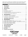
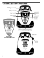
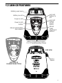
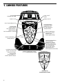
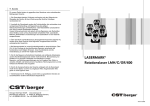
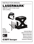
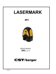
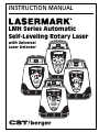
INSTRUCTION MANUAL
LMH Series Automatic
Self-Leveling Rotary Laser
with Universal
Laser Detector
Copyright© 2002 CST/Berger. All rights reserved
The information contained herein is propietary information of CST/Berger, and is subject to
change without notice.
This document shall not be copied or otherwise reproduced without CST/Berger's written consent.
Thank you for purchasing the LaserMark® LMH Automatic Self-Leveling
Rotary Laser. Please read this manual thoroughly before operation.
CONTENTS
1.
LMH Features ................................................................................ 1
2.
Laser Safety ................................................................................... 4
3.
LMH Operation .............................................................................. 4
3.1
3.2
3.2.1
3.3
3.4
3.5
Leveling ........................................................................................................... 4
Re-leveling ....................................................................................................... 5
Axis Drive Error (Spindle Error) ....................................................................... 5
Anti-Drift System (ADS) ................................................................................... 5
Grade Mode: Single Axis Grade (LMH-GR and LMH600 Only) .......................... 6
Grade Mode: Dual Axis Slope (LMH600 Only) .................................................. 8
4.
LMH Applications .......................................................................... 9
4.1
4.2
4.3
Procedures for Ceiling Grid Applications ....................................................... 9
Procedures for Laydown Applications ......................................................... 10
Procedures for General Construction Applications ..................................... 11
5.
LMH Battery Replacement ....................................................... 12
6.
LMH Calibration .......................................................................... 13
6.1
6.1.2
6.1.3
6.2.1
6.2.2
Upright Position Peg Test (X axis) .................................................................
Upright Position Calibration - X axis (LMH, LMH-C, LMH-GR) .......................
Upright Position Peg Test and Calibration - Y axis (LMH, LMH-C, LMH-GR) .
Upright Position Calibration (LMH600) .........................................................
Laydown Position Calibration (LMH600) .......................................................
7.
Care of LMH Instrument ............................................................ 18
8.
LMH Specifications ..................................................................... 18
9.
Troubleshooting ......................................................................... 19
13
14
15
16
17
10. Warranty ...................................................................................... 20
11. Universal Laser Detector .......................................................... 22
1.1 LMH AND LMH-C FEATURES
Rotating Laser Head
Battery Low LED
Anti-Drift
System On
LED
Power On LED
Power On/Off
Button
Anti-Drift
System
On/Off
Button
Battery Compartment Access/
⁄ " x 11 Tripod Mounting Thread
58
SIDE VIEW
LOCATION OF
CALIBRATION BUTTONS
Built-In
Handle
1
1.2 LMH-GR FEATURES
Rotating Laser Head
Anti-Drift
System On
LED
Battery Low LED
Power On LED
Made in USA
Power On/Off
Button
Anti-Drift
System
On/Off
Button
LMH
-GR
ANTI-DRIFT SYSTEM
POWER
Manual Grade Button
(See LMH600)
Manual
Grade
Adjustment
Buttons
LEVEL ON/OFF
Manual
Grade Setting
Made in USA
Battery Compartment Access/
⁄8" x 11 Tripod Mounting Thread
5
LMH
-GR
ANTI-DRIFT SYSTEM
POWER
SIDE VIEW
LEVEL ON/OFF
Manual
Grade Setting
Built-In
Handle
LOCATION OF
CALIBRATION BUTTONS
2
1. LMH600 FEATURES
Self-Leveling
Rotating Laser Head
Power On/Off
Button
Power On LED
Battery Low LED
Out-of-Level Indicator LED
LM600 Self-Leveling Rotary Laser
Scan Mode Button
Scanning to Preset
Angles of 10º, 15º,
45º, 90º and 180º to
Increase Visibility
Variable Speed
Rotation Button
Four Speed Selection.
Speed Decreases
Each Time Button is Pressed
90º
45º
15º
Manual Grade Button
Turns unit to manual
mode to allow
manual grade setting
180º
Manual Grade/Slope
Setting Buttons
Head Positioning Button
for Fast and Easy
Alignment in Vertical/
Horizontal Applications,
Clock-Wise and CounterClock-Wise Rotation.
Pressing and Holding
Button Moves the
Rotating Beam more Quickly
Auto Beam Positioning
Button. Positions the
Laser Dot in Plumb
Down Position
(Vertical Mode), for
Vertical Laydown Set-ups
Battery Compartment Access/
⁄ " x 11 Tripod Mounting Thread
58
LM600 Self-Leveling Rotary Laser
90º
45º
15º
180º
X
Y
LOCATION OF
CALIBRATION BUTTONS
3
2. LASER SAFETY
The use of controls, adjustments, or the performance of procedures other than those specified
herein may result in hazardous radiation exposure.
Do not stare into the laser beams. Do not disassemble the instrument or attempt to perform any
internal servicing. Repair and servicing of this laser
are to be performed only by CST or authorized service centers.
This laser complies with all applicable portions of title
21 of the Code of Federal Regulations set by the Dept. of Health, Education, and Welfare, the Food and Drug Administration, the Center for
Devices, and the Bureau of Radiological Health.
3. LMH SERIES OPERATION
3.1 Leveling
1: Remove the LaserMark® LMH from its case.
The unit is shipped with a battery current
protection insert, which must be removed
before operation. The unit can stand alone
on a level, sturdy surface or be secured to a
5
⁄8" x 11 surveyor’s tripod.
Power On
(if blinking, unit is self-leveling)
2: Press the Power button once, and allow
time (up to 30 seconds) for the unit to selfFig. 1
level. The Power On LED (Fig. 1) and the laser
will blink during this process. Please note, the laser head may begin to
rotate before leveling is complete. The self-leveling speed is approximately 1° per 4 seconds.
3: After self-leveling, the laser head will rotate at 600 RPM. Press the
Power button again to turn the unit off. (Note: for LMH-GR and
LMH600 models, see section 4.3.2 (page 11)
4
3.2 Re-leveling
If the unit is bumped or moved, the unit will automatically attempt to
re-level itself. The Power On LED and the laser will blink during this
process until the unit is level once again. The laser head will resume
rotation at 600 RPM.
Note: For the LMH-GR and LMH600, if the unit is bumped or moved
while in Manual Grade mode, the unit will not re-level itself.
On the job site, it may be necessary to prevent re-leveling in order to
prevent inaccurate measurements by the opAxis Drive Error
erator. The LMH’s Anti-Drift System (Section
(Blinking)
3.3) is used for this purpose.
3.2.1 Axis Drive Error (Spindle Error)
If the LMH is set up or tipped beyond its selfleveling range of ±5°, the laser head will initially attempt to level; however, when the selfleveling limit is reached, the Battery Low and
Anti-Drift System LEDs will blink, indicating an
axis drive error (Fig. 2). Turn the LMH off,
move the unit into a more level position, then
turn the unit on again.
3.3 Anti-Drift System (ADS)
This function is prompted by pressing the
Anti-Drift System button; it clearly signals the
operator when the unit is moved out of position. The ADS LED will remain lit.
Fig. 2
Anti-Drift System On
(Re-level unit if blinking)
Fig. 3
With ADS on, when the H.I. (“height of instrument”) of the unit is altered due to tripod movement or an accidental bump, the laser head
will stop rotation, the laser will blink, and both the Power On and ADS
LEDs will blink. The operator must attend to the unit to affect the relevel process by pressing the ADS button once. Pressing the ADS button twice will turn the ADS feature off.
The default setting is ADS off; the laser will automatically re-level itself
when the unit is moved out of level. ADS is always reset to off when
power is turned off.
5
Y
-A
x
is
3.4 Grade Mode: Single Axis Grade (LMH-GR and LMH600 Only)
The single grade function is ideal for
general site grading, checking excavations, landscaping and drainage,
and more.
Manual grade mode can be
activated by placing the automatic
leveling sensor in the OFF position.
Pressing the manual grade button
will deactivate the sensor.
NOTE: The total percent grade possible is
LMH-GR
from a perfectly level base position. If the
unit is mounted on a tripod head which is not
perfectly level, then the grade percentage range
capable would be reduced by the slope of the
base, as this affects the tilt range of the laser
head. For maximum grade range, ensure a level
tripod head using a spirit level before mounting
your unit.
LMH600
The selected grade can be as much
as a positive or negative 10%, and
set in reference to the Y-axis of the
unit.
Operator can use one of two methods to generate single-axis grade
(Fig. 4). Method 1: Place the unit in the middle of the two points (A
and B) to get a higher distance. Method 2: Place the unit at one point
(A) and locate the other point (B).
On the LMH600, you may first press Variable Rotation button and set
the laser to the desired rotation speed. Press the "MANUAL GRADE"
button to activate Manual Grade Option. Press the ARROW buttons
(Fig. 5B) to adjust to your desired grade.
A
B
"Y" Axis
Beam from
Pivot Point = 2.2"
Method 1
Method 2
Fig. 4
6
The unit will react to "MORE" and "LESS" input (Fig 5A and 5B). Allow
the unit ample time to react to the input provided, between grade
setups or changes.
Fig. 5A
“MORE”
“MORE”
“LESS”
“LESS”
X
Y
LMH600 Only
The Rotating Head
tilts on the X-Axis.
The LEFT ARROW
tilts in the "LESS"
direction.
LMH600 Only: In
Laydown,
the Top Plumb Beam
moves from left to right.
LMH-GR and LMH600
LM600 Self-Leveling Rotary Laser
90º
45º
15º
The Rotating Head
tilts on the Y-Axis.
The UP ARROW
tilts in the "MORE"
direction.
LMH600 Only: In
Laydown, the Top
Plumb Beam moves
upward.
Made in USA
LMH
-GR
180º
The Rotating Head
tilts on the X-Axis.
The RIGHT ARROW
tilts in the "MORE"
direction.
LMH600 Only: In
Laydown,
the Top Plumb Beam
moves from left to right.
The Rotating Head
tilts on the Y-Axis. The
DOWN ARROW
tilts in the "LESS"
direction.
LMH600 Only: In
Laydown, the Top
Plumb Beam moves
downward.
Fig. 5B
7
ANTI-DRIFT SYSTEM
POWER
LEVEL ON/OFF
Manual
Grade Setting
3.5 Grade Mode: Dual Axis Slope
(LMH600 Only)
The dual grade function allows more
specialized site preparations such as
road grading, airport jobs (grading &
paving), irrigation, trenching, landfills,
slopes and embankments, and
pipelaying.
To enter a dual grade setting, press the
Manual Mode (Grade) button. Then press
the ARROW buttons to adjust grade (Fig.
5B). Allow the unit ample time to react to
the button being pressed. Refer to examples in Fig. 6 to predict your results.
Y+
X+
X-
Y+
X-
Y
Target
Y+
X+
X
Y+
X+
X-
Y-
X= –10.00% Y= –10.00%
YY+
X+
X-
Y-
Y+
X-
X= +10.00% Y= +10.00%
X+
Y-
X= –10.00% Y= +10.00%
Fig. 6
8
4. LMH SERIES APPLICATIONS
Use your LaserMark® LMH Series Automatic Self-Leveling Laser for
these and many other projects:
Outdoor General Construction Applications & Site Preparation, Grading
& Excavating, Batterboards and Foundations, Masonry Work, Setting
Concrete Forms, Machinery Installation, Marking Elevation, Septic
Work, Paving Roads, Driveways, Checking Depth of Trenches.
4.1 Procedures for Ceiling Grid Applications (LMH600 Only)
1: Attach the LMH Series to the optional wallmount bracket. Be sure
the control buttons are facing outward. Tightening the locking screw
will secure the unit to the bracket.
2: After installing the first piece of ceiling trim, attach the wallmount
to it. Be sure the wallmount is secure to the trim.
3: Press the Power button. If the out-of-level indicator is
blinking, press the manual grade button to put the unit
into automatic mode. Allow the unit to self-level.
4: Adjust the distance of the
unit from the grid, typically
1.5-inch (38mm) below the
grid. Loosen the adjustment screw
and slide the unit up/down on the
wall mount. When the desired
height has been reached, tighten
the adjustment screw to secure
9
the unit.
5: Install the ceiling grid. Attach the magnetic laser target to the ceiling trim being installed. Adjust the height of the trim until the laser
beam strikes the target.
Note: Placing the unit into Scan Mode will make installation easier and
more effecient.
To place the unit in Scan Mode, press the Scan Mode button until the
rotating laser head stops. Press and hold either clock-wise or counterclock-wise Head Positioning button until the laser beam moves to the
working area. Press the Scan Mode button until the rotating beam is
scanning the necessary angle.
4.2 Procedures for Laydown Applications (LMH600 Only)
1: Place the unit in the laydown position on a flat, level surface.
2: Press the Power button. If the "Out-of-Level" indicator is blinking,
press the Manual Grade button to put the unit in automatic mode.
3: Press the Auto Beam Positioning button; the laser beam will plumb
down over point.
4: Use the left and right Manual Grade buttons for fine adjustment.
LMH600 Shown
10
4.3 Procedures for General Construction Applications
Note: A level plane of laser light is created by the rotating beam of the
LMH Series. The laser light can be used to reference elevations with
the use of a laser detector.
1: Place the unit on a flat, level surface such as a tripod. Setup the unit
in an area where it can not be obstructed and it will be set at a convenient height.
2: Press the Power button. If the "Out-of-Level" indicator (LMH-GR
and LMH600 only) is blinking, press the Manual Grade button to put
the unit in automatic mode.
2a: LMH600 Only – Press the Variable Speed Rotation button to select
the desire rotation speed of the laser head.
3 : Take elevation readings using the plane of laser light as a reference.
To take readings, attach the laser detector to the grade rod and
place the rod at a point to for an elevation reading. Follow the
Detector Operation Procedures in this manual.
11
5. LMH SERIES BATTERY REPLACEMENT
Your LaserMark® level will provide approximately 30 hours of intermittent use (variable
with temperature) with four Alkaline “D” cell
batteries. If the Battery Low LED is lit (Fig. 7),
or the LMH operates erratically, try replacing
the batteries.
Low Battery
1: Remove the battery tray by unscrewing
the plastic nut around the mounting thread
on the bottom of the unit (Fig. 8).
2: Remove the old batteries and replace with
four new “D” cell Alkaline batteries.
Fig. 7
3: Replace the battery tray. Make sure the battery contacts between
the battery pack and the unit compartment are aligned.
NOTE: Do not mix old and new batteries. Replace all batteries at the same time with
new batteries. Remove batteries before storage of the instrument.
Rechargeable Battery Pack
if you are using a rechargeable battery
pack (included with Cat. #57-LMHD [120V]
or #57-LMHE [230V]), your LMH will provide approximately 14 hours of intermittent use with each full charge. The batteries will begin to perform optimally
after five full charges and discharges.
You may charge the battery pack within
the LMH. Ensure that the power is off,
and connect the charging plug to the
charging jack on the bottom of the battery pack. Then plug the charger into the
appropriate 120/230V AC outlet. Charge
time is typically around 8 hours. The LMH
can be charged and used at the same
time, but only a minimal charge will be
applied to the battery pack.
Fig. 8
12
6. LMH SERIES CALIBRATION
Your LaserMark® level is a sealed unit and is
calibrated to precise accuracies at the factory.
However, a calibration check is recommended
before the initial use of your laser, and then
periodically from that point forward. Be sure
to allow time (up to 30 seconds) for the unit
to completely self-level before each check.
Y+
X-
Please note the direction of the X and Y axes
for the unit (Fig. 9). You will need to refer to
this to complete the following steps.
X+
Y-
Fig. 9
6.1 Upright Position Peg Test (X axis)
1: To test the X axis, mount the LaserMark® on a
tripod or a level, sturdy surface and place
approximately 100 feet (30m) away from
100'
a wall. Face the right side of the unit
(30m)
(X+ quadrant) to the wall.
2: Press the POWER button and
allow the unit to self-level. Using
the laser detector, locate and mark
the position of the laser line on the
wall (“A”, Fig. 10).
A
B
3: Loosen the LaserMark® from the
tripod and rotate the instrument
Fig. 10
180°. Ensure that the height of the
tripod does not change, as this will affect your results. Secure and relevel the unit.
4: Again, locate and mark the position of the laser line on the wall
(“B”). No adjustment is necessary if the vertical difference between A
and B is less than 1/8" (3.5mm)
Repeat the above steps to ensure a correct reading. If the distance is
greater than 1/8", you will need to calibrate the X axis (next refer to
6.1.2; for LMH600, refer to 6.2.1).
13
6.1.2 Upright Position Calibration - X axis (LMH, LMH-C, LMH-GR)
1: Keep the unit in its current position. Power
Off the unit.
Calibration Mode
X Axis active
2: Power On the unit while holding the ADS
button down. You will know if Calibration
mode is activated when the Battery Low and
ADS LEDs flash alternately. Then, the ADS LED
will remain lit; this indicates that the unit is
calibrating within the X axis (Fig. 11).
3: Locate the position of the two calibration
Fig. 11
buttons as shown in (Fig. 12), on the LMHGR the UP and DOWN ARROW buttons change the axis increments. The upper button will produce a positive (+)
4: You must raise or lower the beam to center between points A and B
on the wall (Fig. 13). The unit will react to “+” and “–” input within the
X- quadrant, with each single increment moving the beam approximately 1/32" at 100 feet. If B is below A, decrease the increment (-). If B
is above A, increase the increment (+).
5: The adjustments are automatically saved. You must now repeat the
peg test (6.1) to insure you have made the correct calibration. Repeat
calibration if necessary.
B
Calibrated
A
Fig. 13
X- facing
the wall
LMH and LMH-C
Fig. 12
14
6.1.3 Upright Position Peg Test and Calibration - Y axis (LMH,
LMH-C, LMH-GR)
If you wish to test the Y axis at the same time as the X axis, simply
keep the unit on from when you tested the X axis and rotate the unit
90° so that the front of the unit is facing the wall. Press the ADS button to turn the ADS LED off; you are now calibrating within the
Y axis (Fig. 14); follow 6.1, steps 2 through 4.
If you are testing the Y axis at a later time than the X axis, mount the
LaserMark® on a tripod and place approximately 100 feet (30m) away
from a wall, with the front (Y– quadrant) of the unit facing the wall;
follow 6.1, steps 2 through 4.
A
Calibration Mode
Y Axis active
Calibrated
B
Fig. 15
Y+ facing
the wall
Fig. 14
Calibrate as in 6.1.2, adjusting “+” and “–” input as necessary within the
Y+ quadrant (Fig. 15).
If you are unable to calibrate the unit, or if the difference between points A and B is
too great to calibrate within the range of the unit, please contact CST/Berger or an
authorized service center for assistance.
15
6.2.1 Upright Position Calibration (LMH600)
1: Keep the unit in its current position. Power
OFF the unit.
Y+
2: Power ON the unit while holding the ClockWise button down. You will know if Calibration
mode is activated when the Battery Low and Out- Xof-Level LEDs flash alternately. Then, the Power
LED will remain lit.
X+
Y-
3: The ARROW buttons will produce the increment change as shown in figure 17.
Fig. 16
4: follow 6.1.2, steps 4 through 5. Rotate unit 90
degree to calibrate the other axis.
5: Press the POWER button. This will exit Calibration Mode.
Y+
X+
X-
Y+
Fig. 17
16
6.2.2 Laydown Position Calibration (LMH600)
1: Place the unit in the laydown position on a flat, level surface 100
feet (30 meter) from a wall (Fig. 18).
2: Press and hold the Counter-Clockwise Button, and then press the
Power Button. Release both button at the same time.
The Out-of-Level LED and Battery Low indicators blink together, Then
the Power indicator illuminates.
Note: For the most accurate check, allow the unit to operate for at
least 30 seconds before continuing.
3: Place a plumb line at the wall (Fig. 18).
4: Have the rotating beam scan the wall and physically adjust the unit
so the beam is in-line with the plumb line.
5: If the beam is not in-line with the plumb line, use the UP ARROW
and DOWN ARROW buttons to adjust the beam, until it intersects the
plumb line.
Plumb Line
6: Press the POWER button. This will
exit Calibration Mode.
Rotating Beam (Dashed Line) is
shown NOT in-line with plumb
line
Plumb Beam
Fig. 18
17
7. CARE OF LMH INSTRUMENT
Always clean the instrument after use. Use a soft, dry cloth to remove
any dirt or moisture from the instrument. Do not use benzene, paint
thinner, or other solvents to clean the instrument. Remove batteries
before storage of the instrument.
8. LMH SERIES SPECIFICATIONS
Description
Leveling Accuracy
LMH
LMH-C
LMH-GR
LMH600
±1⁄ 16" @100'
±1.5mm@30m
±3⁄ 32" @100'
±2.4mm@30m)
±1⁄ 16" @100'
±1.5mm@30m)
±1⁄ 16" @100'
±1.5mm@30m)
Recommended
Working Range
Up to 2000' (610m) diameter with laser detector
Laser Diode Visible
Red Beam
650 NM
Self-Leveling Range
±5º
Self-Leveling Speed
650 NM
635 NM
635 NM
±3º
±5º
±5º
1º per 4 sec. (approx.)
8" h X 6-1⁄ 4" w X 6-3⁄ 8" d
(203mm X 159mm X 162mm)
Dimensions
Weight
5.5± lbs. (2.5kg) with batteries
Power
Four (4) D cell Alkaline batteries or rechargeable battery pack
Battery Life
Rotation Speed
Operating
Temperature
75± hours intermittent use with Alkaline batteries
(variable with temperature);
14+ hours used w/fully charged battery pack.
600 RPM
600 RPM
600 RPM
Variable
0,150,300,600
RPM
22ºF to 120ºF
(-6ºC to 49ºC)
18
9. TROUBLESHOOTING
The following information lists basic tests that can be performed to
check the LMH in the event of poor performance.
Check Your Batteries: One of the most common causes of performance failures is due to defective or incorrectly installed batteries.
Check to see if any batteries are installed backwards and correct if
necessary.
• Never selectively replace batteries; always replace all of the batteries
at the same time with new batteries. It is recommended, if possible,
that the batteries be checked with a voltmeter or battery tester to
confirm proper voltage.
• Leaky batteries may have damaged the battery contacts in the
battery box.
• Check to see that the battery tray is screwed tightly onto the base of
the unit. Also, the fit between the battery prongs and the batteries
may need adjustment, as this fit may vary over different brands of
battery (especially Energizer™ brand, as they are larger in diameter,
preventing a proper connection).
• Alkaline batteries are recommended for the best performance and
storage life. Rechargeable batteries such as Nickel-Cadmium will
provide performance, but are not as desirable due to their lower
terminal voltage. Low cost standard Carbon-Zinc batteries may be
used in emergencies, but they should be replaced with alkaline
batteries when available.
Rechargeable Battery Pack: For maximum battery life, the battery
pack must contain a full charge. Properly charged, the battery pack
will provide approximately 14 hours of service. As in most Ni-Cd battery packs, the closer to a full charge that the pack has, the longer it
will take to attain a full charge. The batteries will begin to perform optimally after five full charges and discharges.
Unit does not rotate or self-level, or produces Axis Drive Error:
Reset the internal processor by turning power off and on again. You
may also try removing the battery tray for 5 seconds to let the
19
capacitor discharge, then replace the tray and try again.
If the unit rotates but does not self-level, be sure that the Anti-Drift
System is turned off.
LMH600 Errors:
When an error occurs on the
LMH600, turn the unit OFF.
Wait 5 seconds, then turn
unit ON. If error still occurs,
press the Grade Mode button.
Use the ARROW buttons to
rotate the laser head. Then
turn unit OFF and then ON
again. If these procedures do
not correct error, contact
CST/berger.
X—AXIS ERROR
Y—AXIS ERROR
SPINDLE ERROR
20
10. WARRANTY
This LaserMark® LMH Automatic Self-Leveling Rotary Laser is warranted
to the original purchaser to be free from defects in workmanship and
material. CST/Berger will repair or replace any defective part which
may malfunction under normal and proper use within a period of TWO
YEARS from the date of purchase without charge of parts and labor,
once delivered and shipped prepaid to CST together with proof of
date and place of purchase. This warranty is not subject to misuse,
abuse, assignment, or transfer. The exclusive remedy under any and all
warrants and guarantees, expressed or implied, is limited to repair
and/or replacement as provided herein, and CST shall not be liable for
damages from loss or delay of equipment uses, consequential, or incidental damage.
Before returning the unit to CST/Berger, please call (800) 4351859 for a return authorization number from our Customer Service Department.
Please fill out and return the attached warranty registration
card.
21
Universal Laser Detector
1. INTRODUCTION
The LaserMark® Universal Laser Detector aids in locating and targeting
a visible or invisible beam emitted by a rotary laser; perfect for use in
outdoor conditions, where sunlight and distance may make locating
the beam more difficult.
2. FEATURES
LD400 SHOWN
LD400 Includes heavy-duty rod clamp.
Beam
Capture
Window
LCD Readout
Window
50 mm
(2.0 in)
Power ON/OFF
Beam Resolution
Volume ON/OFF
Speaker
LCD Readout
Window
Made in USA
Battery Door
3. POWER
A 9-volt battery will provide up to 3 months of typical usage. When
the unit is turned on and the low battery symbol remains lit, the battery should be replaced.
22
4. OPERATION
1: Mount the unit onto a sighting rod if
you are using one. Turn on the unit by
pressing the ON/OFF pad. The LCD symbols will momentarily flash (Fig. 1) and
the “coarse” beam indicator symbol will
remain lit and the audio signal will be on.
2: Expose the beam capture window of
the laser detector towards the direction
of the rotating laser.
LCD Display
Beam
Resolution
High Beam
Level Beam
Indicator
Low Beam
Speaker
Volume
Battery
Strength
3: Slowly move the laser detector in an
Fig. 1
upward and downward direction until
the LCD beam indicator arrows appear
and/or a pulsing audio signal is heard. Use the Beam Resolution feature to choose between the coarse/low setting, used for approximating level or for initial locating of the center level point, the medium
setting, used for greater accuracy, and the fine/high setting, used for
the most accurate pinpointing of level.
4: Move the detector upward when the low beam indicator light is lit
(with volume on, a short pulsing audio tone is heard). Move the detector downward when the high beam indicator arrow is lit (with volume
on, a long pulsing audio tone is heard). When the beam is level, the
level beam indicator line will be lit and a solid audio tone will be heard.
If the detector is not struck by a laser beam after 5-8 minutes, the
detector will automatically shut itself off to preserve battery life. Turn
the unit back on using the power button.
23
5. SPECIAL FEATURES
This detector has a unique memory feature, which preserves the last
position of the laser beam if the detector is moved out of the plane of
laser light, as well as built in electronic filtering for bright sunlight and
electromagnetic interference. Three distinct audio tones (high, ongrade, and low) assist targeting from a distance.
Features speaker Off, Loud
(105 dBA) and Louder (125+
dBA), fine, medium, and coarse
beam resolution settings, and
front and back LCD displays.
Seven distinct channels of information (Fig. 2) indicate the
Fig. 2
position of the detector in the
plane of laser light. As you move the detector closer to the center, the
arrows fill in to indicate the laser position.
6. CARE OF YOUR UNIVERSAL LASER DETECTOR
This unit is gasket sealed for water and dust protection. Use a soft, dry
cloth to remove any dirt or moisture from the instrument before storage. Do not use benzene, paint thinner, or other solvents to clean the
instrument. Remove battery before long-term storage of the instrument.
7. SPECIFICATIONS
Dimensions: 6.6" h x 3" w x 1" d (169mm x 76mm x 25mm)
Weight: 10 oz. (275g)
Range: up to 2000' (610m)
Beam Detection Sensitivity: Fine, ± .75mm; Medium, ± 1.5mm;
Coarse, ± 3mm (sensitivity based on standard conditions with most lasers; may vary
slightly due to make, manufacturer, beam size, or working conditions)
Readout: LCD, LD400-front and rear windows; LD100N-single window
Power: One 9-volt battery; provides 3 months of typical usage
24
Printed in USA PG 0402 Z93-57-LMHMANUAL