1
SierraFC M164
Fibre Channel Protocol Analyzer
User Manual
Software Version 4.45
Document Version 4.45
November 2013
Teledyne LeCroy Protocol Solutions Group
Trademarks and Servicemarks
Teledyne LeCroy, CATC Trace, and SierraFC Protocol Suite are trademarks of Teledyne LeCroy.
Microsoft and Windows are registered trademarks of Microsoft Corporation.
Intel and Pentium are registered trademarks of Intel Corporation.
All other trademarks and registered trademarks are property of their respective owners.
THE SPECIFICATIONS AND INFORMATION REGARDING THE PRODUCTS IN THIS MANUAL ARE SUBJECT TO CHANGE WITHOUT NOTICE. ALL INFORMATION, EXAMPLES AND RECOMMENDATIONS IN THIS MANUAL ARE BELIEVED TO BE ACCURATE BUT ARE REPRESENTED WITHOUT WARRANTY OF ANY KIND, EXPRESS OR IMPLIED. USERS ARE FULLY RESPONSIBLE FOR THEIR APPLICATION OF ANY PRODUCTS.
THE SOFTWARE LICENSE AND LIMITED WARRANTY FOR THE ACCOMPANYING PRODUCT ARE SET FORTH IN INFORMATION THAT SHIPPED WITH THE PRODUCT AND ARE INCORPORATED HEREIN BY THIS REFERENCE. IF YOU ARE UNABLE TO LOCATE THE SOFTWARE LICENSE OR LIMITED WARRANTY, CONTACT Teledyne LeCroy FOR A COPY.
© 2012, Teledyne LeCroy, Inc. All rights reserved.
This document may be printed and reproduced without additional permission, but all copies should contain this copyright notice.
WEEE Program Teledyne LeCroy Corporation
3385 Scott Blvd.
Santa Clara, CA 95054
TEL: 800‐909‐7112 (USA and Canada)
TEL: 408‐653‐1260 (worldwide)
SierraFC M164 Protocol Analyzer User Manual
ii
Contents
Chapter 1: Introduction.........................................................................................11
Analyzer Overview.........................................................................................................................................11
Receiving Your Analyzer ..............................................................................................................................12
Unpacking the Analyzer ................................................................................................................................12
Analyzer Features..........................................................................................................................................12
LEDs ...............................................................................................................................................................13
Status and Configuration Display ................................................................................................................14
LCD Display and Button Functions for Configuring the Analyzer............................................................14
Set IP Configuration ............................................................................................................................15
IPMode Dynamic .................................................................................................................................15
Installing Your Analyzer............................................................................................................. 16
Software Installation ...........................................................................................................................16
System restart .....................................................................................................................................16
Error Message .....................................................................................................................................16
Hardware Setup .......................................................................................................................... 17
Connecting in General ..................................................................................................................................17
Cables to Use ......................................................................................................................................18
Expandability .............................................................................................................................. 18
Removing Expansion Cards .........................................................................................................................18
Cascading with CATC SYNC Expansion .....................................................................................................21
Connecting a SierraFC M164 and a Summit T3-16 via the CATC Sync Expansion Card (ACC-EXP-002-X) ....21
Select Device .................................................................................................................................................23
Connecting via Ethernet ............................................................................................................ 26
Connecting to a Network ..............................................................................................................................26
Connecting using a Hub, Switch, or Similar Device...................................................................................27
Analyzer Connected Directly to the Host Machine Using a Ethernet Cable ............................................27
Connecting Over Different Subnets.............................................................................................................27
Connecting Via USB ................................................................................................................... 27
Launching Your Analyzer .......................................................................................................... 28
Operating in Simulation Mode................................................................................................... 28
SierraFC M164 Protocol Analyzer User Manual
3
Teledyne LeCroy
Contents
Using the Software ..................................................................................................................... 28
Protocol Analyzer ....................................................................................................................... 30
Viewing Captured Data .................................................................................................................................30
Configuration .................................................................................................................................................31
Port Status .....................................................................................................................................................31
Statistical Reports .........................................................................................................................................31
InFusion..........................................................................................................................................................31
CrossSync Control Panel .............................................................................................................................31
Chapter 2: Protocol Analysis ...............................................................................33
Supported Protocols .................................................................................................................. 33
Easy Mode (Pre-Defined Setups) .............................................................................................. 33
Main Window..................................................................................................................................................33
Analyzer Settings ..........................................................................................................................................34
Buffer Size and Segments ..................................................................................................................34
Trigger Position ...................................................................................................................................34
Auto Run ..............................................................................................................................................35
Training Signal Pack Mode ................................................................................................................35
Last Captured Trace File ....................................................................................................................35
Analyzer Settings ................................................................................................................................35
Set Protocol Error Detection ..............................................................................................................35
Project Overview .................................................................................................................................35
Capture Tab....................................................................................................................................................35
Software Menus and Toolbar .............................................................................................................37
Run Hardware ......................................................................................................................................37
Saving a Trace Capture ......................................................................................................................39
CrossSync Control Panel .............................................................................................................................40
Launching the CrossSync Control Panel .........................................................................................40
Projects ................................................................................................................................................41
Project File Types ...............................................................................................................................41
Example Projects ................................................................................................................................41
Run an Example Analysis Project .....................................................................................................42
Patterns and Data Capture Setup ................................................................................................................44
Choose a Parameter ...........................................................................................................................45
Include Patterns ..................................................................................................................................45
Exclude Patterns .................................................................................................................................45
Pre- and Post Trigger Data Capture.............................................................................................................47
Defining Patterns ................................................................................................................................47
Basic Patterns .....................................................................................................................................48
FCP Patterns ........................................................................................................................................52
ARB Patterns .......................................................................................................................................56
4
SierraFC M164 Protocol Analyzer User Manual
Contents
Teledyne LeCroy
ELS Patterns ........................................................................................................................................57
GS Patterns ..........................................................................................................................................60
SW Patterns .........................................................................................................................................63
FICON ...................................................................................................................................................66
FCAE ....................................................................................................................................................79
FCVI ......................................................................................................................................................90
FCAV ....................................................................................................................................................91
ADVB ....................................................................................................................................................94
VSAN Basic ........................................................................................................................................102
VSAN FCP ..........................................................................................................................................104
VSAN ARB .........................................................................................................................................109
VSAN ELS Patterns ...........................................................................................................................110
VSAN-GS Patterns ............................................................................................................................113
VSAN-SW Patterns ............................................................................................................................116
VSAN-FICON ......................................................................................................................................119
VSAN FCAE .......................................................................................................................................132
VSAN-FCAE-1553 ..............................................................................................................................133
VSAN-FCVI .........................................................................................................................................143
VSAN-FCAV .......................................................................................................................................144
VSAN-ADVB .......................................................................................................................................146
Custom Frame ...................................................................................................................................147
Protocol Errors ..................................................................................................................................149
Trigger Setup ...............................................................................................................................................149
Snapshot Mode .................................................................................................................................150
Manual Trigger Mode ........................................................................................................................151
Pattern/Event/Infusion Trigger Mode ..............................................................................................152
Timers/External .................................................................................................................................157
Basic Patterns ...................................................................................................................................159
FCP Patterns ......................................................................................................................................160
ARB ....................................................................................................................................................160
ELS .....................................................................................................................................................160
GS .......................................................................................................................................................160
SW ......................................................................................................................................................161
FICON .................................................................................................................................................161
FCAE ..................................................................................................................................................161
FCAE-1553 .........................................................................................................................................161
FCAE-RDMA ......................................................................................................................................162
FCVI ....................................................................................................................................................162
FCAV ..................................................................................................................................................163
ADVB ..................................................................................................................................................163
VSAN Basic ........................................................................................................................................163
VSAN-FCP ..........................................................................................................................................163
SierraFC M164 Protocol Analyzer User Manual
5
Teledyne LeCroy
Contents
VSAN-ARB .........................................................................................................................................164
VSAN-ELS ..........................................................................................................................................164
VSAN-GS ............................................................................................................................................164
VSAN-SW ...........................................................................................................................................164
VSAN-FICON ......................................................................................................................................164
VSAN-FCAE-ASM ..............................................................................................................................165
VSAN-FCAE-1553 ..............................................................................................................................165
VSAN-FCAE-RDMA ...........................................................................................................................165
VSAN-FCVI .........................................................................................................................................166
VSAN-FCAV .......................................................................................................................................167
VSAN-ADVB .......................................................................................................................................167
Custom Frame ...................................................................................................................................167
Protocol Errors ..................................................................................................................................167
Sequential Trigger Mode ..................................................................................................................167
Pre-Trigger .........................................................................................................................................170
Project Settings ...........................................................................................................................................171
Buffer Size and Segments ................................................................................................................172
Trigger Position .................................................................................................................................172
Auto Run ............................................................................................................................................172
Trace File Name .................................................................................................................................173
Analyzer Settings ..............................................................................................................................174
Notes ..................................................................................................................................................176
Advanced Mode (User-Defined) .............................................................................................. 176
Working in Advanced Mode .......................................................................................................................177
Setting Trigger Conditions ...............................................................................................................178
Multi-Link Triggering ........................................................................................................................179
Set Timers ..........................................................................................................................................179
Useful Key Sequences ......................................................................................................................180
Project Settings .................................................................................................................................180
Notes ..................................................................................................................................................180
Chapter 3: Display Manipulation .......................................................................181
Viewer Display .......................................................................................................................... 181
Quick View ...................................................................................................................................................184
Switching Views........................................................................................................................ 185
Spreadsheet View........................................................................................................................................186
Add, Edit and Delete Columns .........................................................................................................189
Frame Inspector View .................................................................................................................................190
Raw Data View - Frame Inspector View for 64b/66b Decoding .....................................................191
Packet View..................................................................................................................................................193
Text View ......................................................................................................................................................194
6
SierraFC M164 Protocol Analyzer User Manual
Contents
Teledyne LeCroy
Bus Utilization View ....................................................................................................................................194
Bus Utilization Buttons ...............................................................................................................................196
Statistical Report View................................................................................................................................196
Customize Display.......................................................................................................................................197
Show/Hide Port ..................................................................................................................................197
Show/Hide Field ................................................................................................................................197
Related Frames .................................................................................................................................199
Choose Data Format .........................................................................................................................199
Data Payload View.......................................................................................................................................200
Compare Two Data Payloads ...........................................................................................................201
Tile Horizontally All Views ................................................................................................................202
Verification Scripts ...........................................................................................................................202
Port Status ...................................................................................................................................................202
Toolbars .......................................................................................................................................................204
Enabling Tool Bars ...........................................................................................................................204
Main Toolbar ......................................................................................................................................205
Show View Type Toolbar ..................................................................................................................205
Trace Viewer Toolbar ........................................................................................................................205
Viewer Setting Toolbar .....................................................................................................................206
Cursor Position Status Bar.........................................................................................................................207
Show Layer Toolbar ....................................................................................................................................207
Status Bar.....................................................................................................................................................208
Recording Progress ..........................................................................................................................208
Recording Status ..............................................................................................................................208
Recording Activity.......................................................................................................................................209
Search Status...............................................................................................................................................209
Statistical Report ...................................................................................................................... 209
Report between Cursors.............................................................................................................................210
Report between Events...............................................................................................................................211
Statistical Report Content ..........................................................................................................................211
Report Options ............................................................................................................................................212
Ordered Sets ................................................................................................................................................212
Frame Report ...............................................................................................................................................212
Bus Conditions Report ...............................................................................................................................214
SCSI Commands Report .............................................................................................................................215
Protocol Errors Report................................................................................................................................215
Ports Report.................................................................................................................................................216
Pending IO Report .......................................................................................................................................217
ELS Commands ...........................................................................................................................................218
GS Commands.............................................................................................................................................219
SW Commands ............................................................................................................................................220
AL Commands .............................................................................................................................................221
Exchange Performance Report ..................................................................................................................221
Statistical Report Toolbar ........................................................................................................ 222
SierraFC M164 Protocol Analyzer User Manual
7
Teledyne LeCroy
Contents
Export as Microsoft® Excel file..................................................................................................................222
Save as Text file...........................................................................................................................................222
Print Statistical Report................................................................................................................................222
Print Preview................................................................................................................................................223
Report Display Settings ..............................................................................................................................223
Link With Sample View ...............................................................................................................................224
Formatting the Statistical Report View................................................................................... 225
Filtering Column Content ...........................................................................................................................225
Sorting Column Content .............................................................................................................................225
Hiding Columns ...........................................................................................................................................225
Formatting Columns ...................................................................................................................................225
Tools .......................................................................................................................................... 225
Self Test........................................................................................................................................................225
Self Test Tabs ..............................................................................................................................................226
Running Verification Script Engine (VSE).................................................................................................227
Run Script ....................................................................................................................................................228
Settings ..............................................................................................................................................228
Right-click Script Menu Options ......................................................................................................230
Quick Filtering........................................................................................................................... 231
Filter Setup in Advanced Mode ..................................................................................................................232
Selectable Filter Options ..................................................................................................................233
Enable Filter .......................................................................................................................................235
Using Cursors and Bookmarks ............................................................................................... 235
Cursors.........................................................................................................................................................235
Quick Search............................................................................................................................. 239
Search Setup in Advanced Mode...............................................................................................................240
Save Search Setup ......................................................................................................................................241
Search From.................................................................................................................................................241
Search Sub Items ........................................................................................................................................242
Search Logic ................................................................................................................................................242
Search Direction ..........................................................................................................................................242
Search For....................................................................................................................................................242
Viewer Configuration................................................................................................................ 244
Trace Viewer Configuration........................................................................................................................244
Port Configuration.......................................................................................................................................247
Port Calibration............................................................................................................................................248
SFP Diagnostics ................................................................................................................................249
Floating License ..........................................................................................................................................249
Software Settings ..................................................................................................................... 250
Sampling Memory Usage Optimization .....................................................................................................251
If the Sampling Memory Usage Optimization Option is Checked ................................................251
If the Sampling Memory Usage Optimization Option is Not Checked .........................................252
8
SierraFC M164 Protocol Analyzer User Manual
Contents
Teledyne LeCroy
Set Port Alias ...............................................................................................................................................253
User-Defined Decoding...............................................................................................................................254
External Trig Setting ...................................................................................................................................255
Update Sierra Device...................................................................................................................................256
Setup IP ..................................................................................................................................... 257
Connecting the SierraFC M164 to a Host Machine System Over Ethernet ............................................257
Configuring the System ..............................................................................................................................258
Dynamic Configurations ...................................................................................................................258
Static Configurations ........................................................................................................................259
Ethernet Connectivity Through a Different Subnet..................................................................................260
Set Address Alias ........................................................................................................................................261
All Connected Devices ............................................................................................................. 262
Help Menu.................................................................................................................................. 262
Help Topics ..................................................................................................................................................262
VSE Help Topics ..........................................................................................................................................262
Update License ............................................................................................................................................262
Display License Information.......................................................................................................................263
Check for Updates.......................................................................................................................................263
About ............................................................................................................................................................263
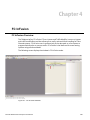
Chapter 4: FC InFusion.......................................................................................265
FC InFusion Overview .............................................................................................................. 265
Key Features ............................................................................................................................. 266
Interface..................................................................................................................................... 267
Buttons .........................................................................................................................................................267
Menus ...........................................................................................................................................................268
Scenario Windows (Main Library)..............................................................................................................269
Library ..........................................................................................................................................................271
Port Configuration for FC InFusion ........................................................................................ 272
FC InFusion Scenarios............................................................................................................. 274
Scenarios Overview ....................................................................................................................................274
Settings in Simple Mode .......................................................................................................... 276
Settings ........................................................................................................................................................276
Arm Detail.....................................................................................................................................................276
Jam Details...................................................................................................................................................276
Settings in Advanced Mode..................................................................................................... 282
Scenario Actions .........................................................................................................................................289
Available Resources ...................................................................................................................................295
Using Counters in Events and Actions ...........................................................................................296
Capturing a Data Dword ...................................................................................................................297
SierraFC M164 Protocol Analyzer User Manual
9
Teledyne LeCroy
Contents
Using Captured Data Dwords ..........................................................................................................298
Dword Matcher ..................................................................................................................................299
Global Rules.................................................................................................................................................300
Sequences....................................................................................................................................................300
Scenario Libraries .......................................................................................................................................301
Main Library .................................................................................................................................................302
File Libraries ................................................................................................................................................302
Scenario Properties.....................................................................................................................................303
Scenario Events...........................................................................................................................................304
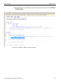
Scenario Examples................................................................................................................... 306
Example 1 in Simple Mode .........................................................................................................................306
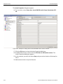
Example 2: Insert DWORD in Advanced Mode .........................................................................................308
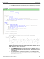
Creating Global Rules .......................................................................................................................308
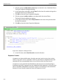
Adding a Sequence ...........................................................................................................................311
Example 3: Using Timers............................................................................................................................316
Sequence Creation ......................................................................................................................................317
Summary of Scenario Creation ..................................................................................................................318
Running Scenarios ................................................................................................................... 318
Scenario Batch Files ................................................................................................................ 324
Script Workspace ........................................................................................................................................324
Error Checking.............................................................................................................................................327
Log ................................................................................................................................................................328
Statements ...................................................................................................................................................328
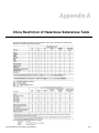
Appendix A: China Restriction of Hazardous Substances Table ...................333
Appendix B: How to Contact Teledyne LeCroy................................................335
Index:.................................................................................................................. 337
10
SierraFC M164 Protocol Analyzer User Manual
Chapter 1
Introduction
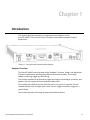
This manual describes installation and operation of the Teledyne LeCroy
SierraFC M164™ Fibre Channel Protocol Analyzer and includes examples of typical applications.
Figure 1.1: LeCroy SierraFC M164 Protocol Analyzer
Analyzer Overview
The SierraFC M164 Protocol Analyzer helps Hardware, Firmware, Design, and Application Engineers troubleshoot and diagnose problems within their product. The analyzer supports capturing, triggering, and filtering.
The Analyzer provides for bi‐directional trigger and capture of exchanges, primitives, and patterns. You can capture all frames and/or exclude traffic. The Analyzer has a USB port and an Ethernet port to connect to a computer. You can cascade analyzer units for higher port counts. You can trigger manually or trigger on a specific Event.
The Analyzer provides a full range of views and statistical reports.
SierraFC M164 Protocol Analyzer User Manual
11
Teledyne LeCroy
Receiving Your Analyzer
The analyzer package includes the following components:
SierraFC M164 Analyzer identified in the packing list
SierraFC M164 Quick Start
USB A‐B 2.0 cable, 1.8 meter
Ethernet cable, 10 feet
Three‐Prong AC power cord
Rack Mount and Rack Mount Installation Guide
Installation CD ROM with software and documentation
Unpacking the Analyzer
Inspect the received shipping container for any damage. Unpack the container and account for each of the system components listed on the accompanying packing list. Visually inspect each component for absence of damage. In the event of damage, notify the shipper and Teledyne LeCroy Corporation. Retain all shipping materials for shipper’s inspection.
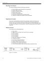
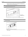
Analyzer Features
The Analyzer has the following features:
Power Switch
Trigger, Error, Link, Speed, and Frame LEDs (see next page)
Port 1 connector
Port 2 connector
Port 3 connector
Port 4 connector
Status and Configuration LCD Display
Configuration Buttons
Front Panel Configuration Buttons
External Trigger Input and Output
USB port for host machine connectivity
Ethernet port for network connectivity
19‐inch Rack Mountable. Refer to the Rack Mount Installation Guide.
Figure 1.2: Front Panel
12 SierraFC M164 Protocol Analyzer User Manual
Teledyne LeCroy
On the back, the Analyzer has:
Power In
STX SYNC Expansion Card In/Out data ports (optional)
Figure 1.3: Back Panel
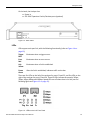
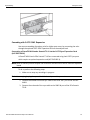
LEDs
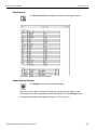
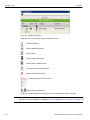
LEDs support each port link, with the following functionality (refer to Figure 1.4 on page 13):
Trigger
Blue
Illuminates when a trigger occurs.
Error
Red
Illuminates when an error occurs.
Link
Yellow
Illuminates when a link is established.
Frame
Green
After the link is established, indicates traffic on the bus.
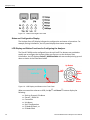
There are five LEDs on the left of the analyzer for ports P1 and P2, and five LEDs on the right of the analyzer for ports P3 and P4. These 10 LEDs indicate the speed of 1Gbps, 2Gbps, 4Gbps, 8Gbps and 16Gbps. Speed LEDs are off when there is no link (see the following figure and Figure 1.2 on page 12).
Figure 1.4: LEDs on the Left Front Panel
SierraFC M164 Protocol Analyzer User Manual
13
Teledyne LeCroy
Figure 1.5: LEDs on the Right Front Panel
Status and Configuration Display
The Analyzer front LCD display indicates the configuration and status of operations. For example, during initialization, the LCD panel displays boot status messages.
LCD Display and Button Functions for Configuring the Analyzer
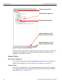
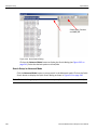
The SierraFC M164 can be configured from the unit itself. Five buttons are provided to enable you to configure the Analyzer. When you first turn on the Analyzer, after initialization, the LCD displays SierraFC_M164 Available with two arrows pointing up and down as shown in the illustration below.
Up Button
SierraFC_M164
Left
Button
Available
LCD Display
Right
Button
Down Button
Center
Button
Figure 1.6: LCD Display and Button on the Front Panel
When connected via ethernet or USB, the Up and Down buttons display the following:
14 Static or Dynamic IP Address
SierraFC_ M164 SN
Connection Unit Name
Set IP Configuration
IP Mode Dynamic, or
IP Mode Static
SierraFC M164 Protocol Analyzer User Manual
Teledyne LeCroy
The Left and Right buttons are used to change the configuration properties.
The LCD will display Button Inactive In This MenuItem if the button does not serve any purpose for that selection.
Perform the following steps to set IP Configuration, Static on Dynamic IP using the buttons and the LCD display on the Analyzer:
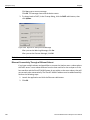
Set IP Configuration
To set IP Configuration:
1. Press the Up Button once to get into the Set IP Configuration mode.
2. Press the Center Button once to select Set IP Configuration.
Set IP Mode Static is displayed in the LCD display. If you do not want to set IP Mode Static, press the Up Button to set the IP Mode Dynamic, see “IPMode Dynamic” on page 15).
3. Press the Center Button once to select Set IP Mode Static.
The Static IP address (for example: 188.168.040.036) is displayed in the LCD display.
4. Press the Center Button once to set the Static IP address.
The first numeral of the IP address will start blinking.
5. Use the Up Button or Down Button to change the IP Address.
6. Press the Right Button or Left Button to move to the right or left to change each component of the static or dynamic IP address and change it using step 5.
7. Once the IP Address is set, press the center button to select it.
8. Press the Up Button once to Accept and Reboot.
9. Press the Up Button once Cancel the Changes.
10. Press the Up Button once to set the Gateway address. Repeat steps 4 through 9 to set the Gateway address.
11. Press the Up Button once to set the Subnet Mask address. Repeat steps 4 through 9 to set the Subnet Mask address.
12. Press the Up Button once to set the Static IP address. Repeat steps 4 through 9 to set the Static IP address.
13. Press the Center Button once to confirm reboot. The LCD display will read Center Button to Confirm Reboot.
14. The Analyzer will reboot. The LCD display will display the new IP Configuration.
IPMode Dynamic
Perform the following steps to set IP Mode Dynamic on the Analyzer:
1. Press the Up Button once to get into the Set IP Configuration mode.
2. Press the Center Button once to select Set IP Configuration.
Set IP Mode Dynamic is displayed in the LCD display.
3. Press the Center Button once to select Set IP Mode Dynamic.
The Dynamic IP address (for example: 188.168.040.036) is displayed in the LCD display.
SierraFC M164 Protocol Analyzer User Manual
15
Teledyne LeCroy
Installing Your Analyzer
4. Press the Center Button to select it.
5. Press the Up Button once to Accept and Reboot.
6. Press the Up Button once Cancel the Changes.
Installing Your Analyzer
Software Installation
The software works on systems using the Windows® XP, Windows Vista, Windows Server 2003, 2008 and Windows 7 operating systems.
1. Insert the Installation CD‐ROM into the CD drive on the host machine.
2. The installation automatically starts setup, unless Auto Run is off. In that case, select the CD‐ROM from “My Computer” and click Setup.
3. After the warning to close all other programs and before starting the installation, the Install component selection opens.
4. Select components for installation.
5. Click Next to complete the installation.
System restart
You must restart your computer before you can use your Analyzer software.
Error Message
If you get an error message during installation of the drivers for Window, consult your system administrator. Your system may allow only administrator‐level users to copy such driver files.
16 SierraFC M164 Protocol Analyzer User Manual
Teledyne LeCroy
Hardware Setup
Hardware Setup
The hardware setup is described below.
Connecting in General
Note: You must install the software before connecting the analyzer to the host machine for the first time.
To set up the analyzer:
1. Connect the analyzer to a 100V–240V, 50Hz–60Hz, power outlet and turn on the Power switch.
At power on, the analyzer will go through initialization as shown on the LCD display.
2. Connect the USB cable between the SierraFC M164 USB port and a USB port on the host machine. The host machine operating system detects the analyzer and driver files.
(See “Connecting via Ethernet” on page 26 for Ethernet connectivity.)
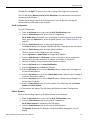
3. Connect the analyzer as shown in the following figure. The figure shows one possible connection from an Initiator to a hard drive.
Figure 1.7: Analyzer Connections
SierraFC M164 Protocol Analyzer User Manual
17
Teledyne LeCroy
Expandability
Cables to Use
Connect from Hard Drives using SFP and a cable suitable for your setup. Connect from Initiators using SFP and a cable suitable for your setup. Figure 1.8: Analyzer Connections
Expandability
You can expand by:
Cascading with CATC SYNC Expansion Cards Using the Power Expansion Card (optional) You can remove expansion cards with two simple tools.
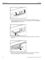
Removing Expansion Cards
You can remove expansion cards using two tools:
Standard (flat blade) 3/16” screwdriver
Teledyne LeCroy Extraction Tool (part number 230‐0160‐00
To remove an expansion card, follow these steps:
18 SierraFC M164 Protocol Analyzer User Manual
Teledyne LeCroy
Expandability
1. Unplug the system from AC power and turn the system so the expansion port is facing you. Note the two retaining screws and the holes for the extraction tool that are located on the panel of the expansion card.
Note: The SierraFC M164 Protocol Analyzer does not support the power expansion card. The method of inserting other expansion cards is the same.
Holes in the
Expansion Card
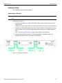
2. Insert the extraction‐tool prongs into the holes in the expansion card panel.
Note: If the prongs do not slip easily into the holes, use a small nail file or similar device to remove paint from the prongs
3. Rotate the extraction tool to a horizontal position to lock the prongs into place and make a handle
SierraFC M164 Protocol Analyzer User Manual
19
Teledyne LeCroy
Expandability
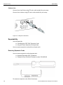
4. Using the screwdriver, loosen both retaining screws by rotating them counter‐
clockwise approximately two full turns, until feeling slight resistance. Do not force the retaining screws after two turns.
5. Using the extraction tool as a handle, gently wriggle the expansion card forward about 1/8”.
6. Repeat steps 4 and 5 approximately three times, until the card is free from the retaining screws and you can remove the card from the system.
20 SierraFC M164 Protocol Analyzer User Manual
Teledyne LeCroy
Expandability
Cascading with CATC SYNC Expansion
You can use cascading of analyzer units for higher port count, by connecting the units through the optional CATC SYNC Expansion Card on the analyzer back.
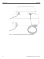
Connecting a SierraFC M164 and a Summit T3-16 via the CATC Sync Expansion Card
(ACC-EXP-002-X)
A SierraFC M164 and a PCIe Summit T3‐16 are connected using their CATC Sync ports which require an optional expansion card (ACC‐EXP‐002‐X).
Note: Refer to relevant protocol analyzer user manual for instructions on how to install the expansion board.
To do so perform the following steps:
1. Make sure to stop any recordings in progress.
Note: You may plug/unplug the sync cable while the analyzer unit is powered on.
2. Connect the female end of the sync cable to the SYNC OUT port of the SierraFC M164.
3. Connect the male end of the sync cable to the SYNC IN port of the PCIe Summit T3‐16.
SierraFC M164 Protocol Analyzer User Manual
21
Teledyne LeCroy
Expandability
Figure 1.9: An Example of Connecting a SierraFC M164 and a Summit T3-16
22 SierraFC M164 Protocol Analyzer User Manual
Teledyne LeCroy
Expandability
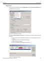
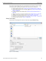
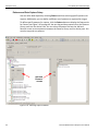
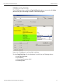
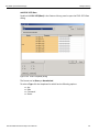
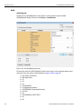
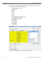
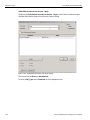
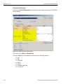
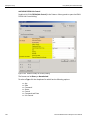
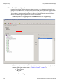
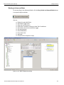
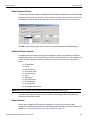
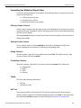
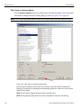
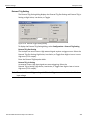
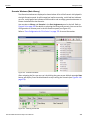
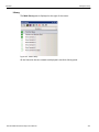
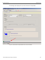
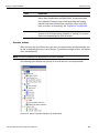
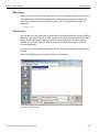
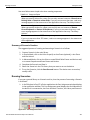
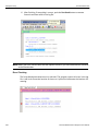
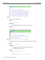
Select Device
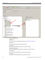
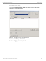
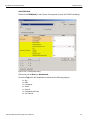
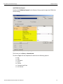
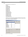
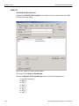
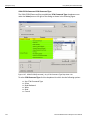
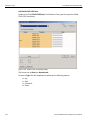
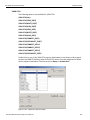
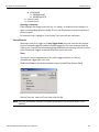
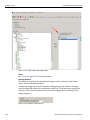
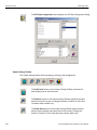
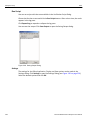
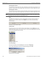
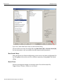
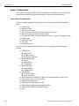
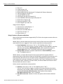
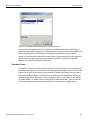
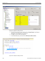
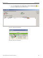
After you start the software, click on Configuration and select All Connected Devices (see the following screen capture).
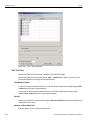
Figure 1.10: Connecting to Device(s)
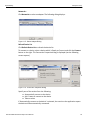
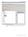
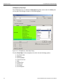
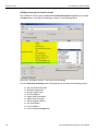
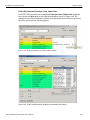
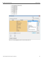
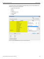
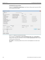
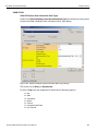
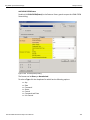
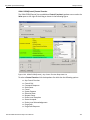
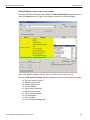
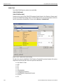
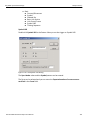
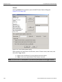
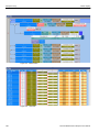
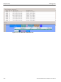
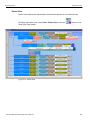
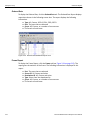
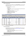
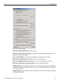
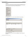
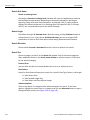
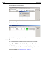
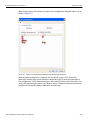
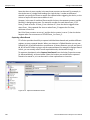
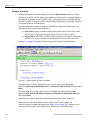
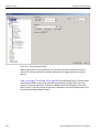
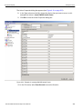
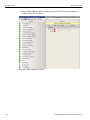
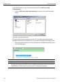
The following Select Device dialog displays. The colors in the ‘Location’ column mean the following:
Red: Firmware and/or BusEngine components need to be updated to the latest version
Light Blue: The device is ready to be connected.
Yellow: The device is locked.
Green: The software is connected and ready to run
Figure 1.11: Select Device Dialog
SierraFC M164 Protocol Analyzer User Manual
23
Teledyne LeCroy
Expandability
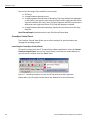
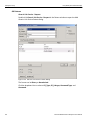
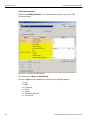
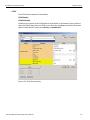
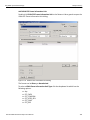
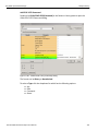
Note: Click Refresh Device List to display all the devices on the network.
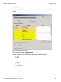
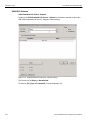
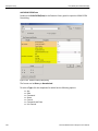
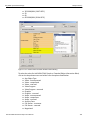
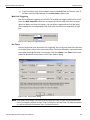
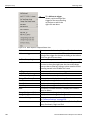
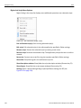
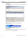
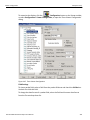
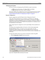
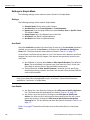
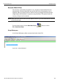
The Select Device dialog displays the following buttons:
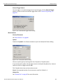
Set Alias Name
Click Set Alias Name to display the Set device alias name dialog as shown below.
Figure 1.12: Set Device Alias Name Dialog
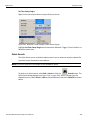
Disconnect
Click Disconnect to disconnect a device.
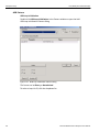
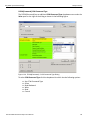
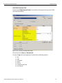
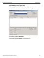
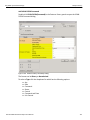
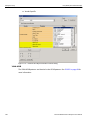
Add Device...
Click Add Device to add a device with a static IP address.
Figure 1.13: Add Device with Static IP Dialog
Remove Device
Click Remove Device to remove a previously added device.
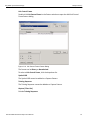
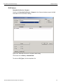
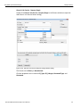
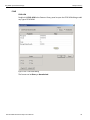
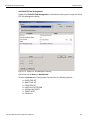
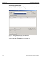
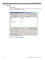
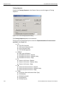
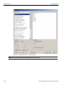
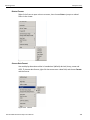
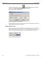
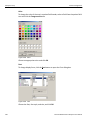
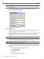
IP Settings...
Click IP Setting to reset IP settings of a device. The following IP Setting dialog displays. Press Tab to move between fields.
Figure 1.14: IP Setting Dialog
24 SierraFC M164 Protocol Analyzer User Manual
Teledyne LeCroy
Expandability
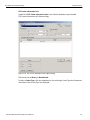
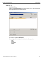
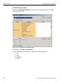
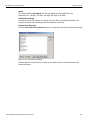
Networks...
Click Networks to select an adapter. The following dialog displays.
Figure 1.15: Select Adapter Dialog
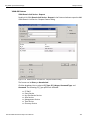
Refresh Device List
Click Refresh Device List to refresh the device list.
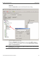
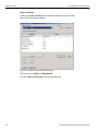
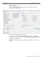
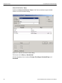
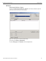
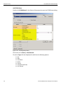
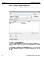
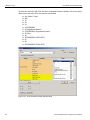
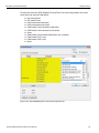
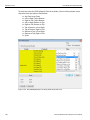
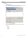
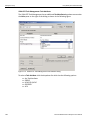
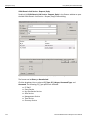
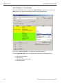
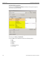
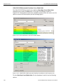
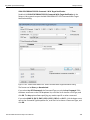
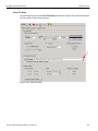
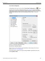
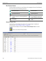
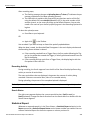
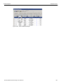
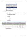
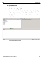
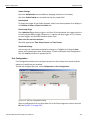
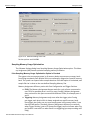
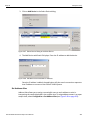
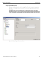
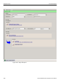
To connect to a device, select a device which is Ready to Connect and click the Connect button on the right. The Connection Properties dialog is displayed (see the following screen capture).
Figure 1.16: Connection Properties Dialog
Specify one of the actions from the following:
Automatically connect to the device
Ask if I want to connect to the device
Take no action
If ‘Automatically connect to the device’ is selected, the next time the application opens the device will be automatically connected.
SierraFC M164 Protocol Analyzer User Manual
25
Teledyne LeCroy
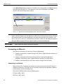
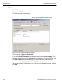
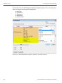
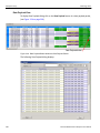
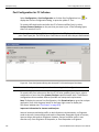
Connecting via Ethernet
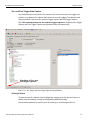
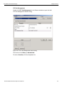
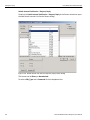
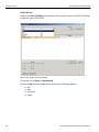
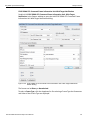
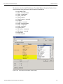
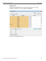
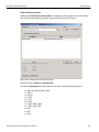
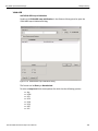
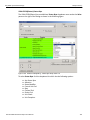
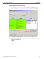
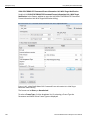
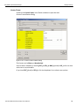
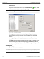
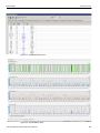
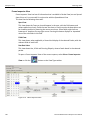
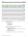
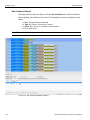
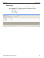
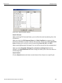
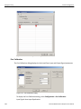
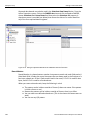
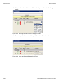
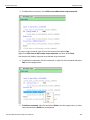
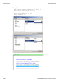
In the Select Device dialog chained or cascaded units are displayed in the Device column with a [ (square bracket) icon. The sequence of the units is displayed in the Order column. See the following screen capture.
Figure 1.17: Select Device Dialog Displaying Unit 1 and Unit 2 Chained
Note: When using STX Sync cards, you need to manually specify the order of the chained units. To match your unit sequence to the address for each unit in the Select Device dialog, click the pull down tab under the Order heading (on the right side) and select unit numbers: 1 for Unit 1, 2 for Unit 2, and so on. This determines the order in which the cascaded ports appear in the trace. When using the CATC Sync cards the order is automatically detected.
IMPORTANT!
Power up all units before starting the software.
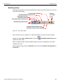
Connecting via Ethernet
The Ethernet connection can have any of these configurations:
1. Analyzer connected to a network using a hub, switch, Gigabit Ethernet interface, or similar device.
2. Analyzer connected to the host machine (machine running the application software), using a hub, switch, Gigabit Ethernet interface, or similar device.
3. Analyzer connected directly to the host machine using an Ethernet cable. Connecting to a Network
When connected to a network, the analyzer can communicate with the DHCP server to establish a connection. The DHCP server continually sends the next available IP address to the analyzer until the software starts. The SierraFC M164 product uses the following ports:
TCP Ports: 4000 ‐ 4003
UDP Ports: 4027 ‐ 4029
26 SierraFC M164 Protocol Analyzer User Manual
Teledyne LeCroy
Connecting Via USB
Connecting using a Hub, Switch, or Similar Device
When connected to the host machine using a hub, switch, Gigabit Ethernet interface, or similar device, the Analyzer must be given a static IP address such that it will reside on the same subnet as the host machine. See Figure 1.14 on page 24 to set the IP address. To add the IP address to the Select Device dialog, use the Add Device button (see Figure 1.13 on page 24).
Analyzer Connected Directly to the Host Machine Using a Ethernet Cable
When connected to the host machine using a crossed ethernet cable, the Analyzer must be given a static IP address such that it will reside on the same subnet as the host machine. See Figure 1.14 on page 24 to set the IP address. To add the IP address to the Select Device dialog, use the Add Device button (see Figure 1.13 on page 24). Connecting Over Different Subnets
If the host machine (with the Sierra software) and SierraFC M164 are on the same subnet, they will see each other’s broadcasts, and the SierraFC M164 application will automatically appear in the Select Device dialog, from which you can select a device (as described in the previous section).
If the host machine and SierraFC M164 do not reside on the same subnet, they will not see each other automatically. You must add the SierraFC M164 IP address manually. To add the IP address, use the Add Device button (see Figure 1.13 on page 24). Connecting Via USB
To set up the Analyzer using a USB connection: 1.
2.
3.
4.
5.
6.
7.
Remove the Analyzer from its shipping container. Insert the Installation CD. Connect the Analyzer to a power outlet using the provided power cord. Connect the USB port to a USB port on the PC using a USB cable. Turn on the rear power switch and the front power switch. Click Next after you see the Add New Hardware Wizard window. Follow the Microsoft® Windows® on‐screen Plug‐and‐Play instructions for the automatic installation of the Analyzer as a USB device on your PC. (The required USB files are included on the Installation CD.)
8. Click Finish when you see the message that says “Windows has finished installing the software that your new hardware requires” and the file has been installed in your PC. Do not change from USB to Ethernet, or back, without power cycling the Analyzer.
To connect the Analyzer to a host machine via ethernet, refer to“Connecting the SierraFC M164 to a Host Machine System Over Ethernet” on page 257.
SierraFC M164 Protocol Analyzer User Manual
27
Teledyne LeCroy
Launching Your Analyzer
Launching Your Analyzer
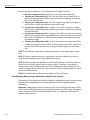
To launch the software, double‐click the FC Icon in the Program Manager Window.
Click OK to display the software.
Operating in Simulation Mode
The system operates in Simulation Mode by default if the software detects no hardware. However, you can operate in Simulation Mode directly, without installing the Analyzer hardware. The Analyzer software launches and displays the appropriate tool bar, but with the limitation that the Analyzer operates only on static, previously captured, bus data.
Limitations
Simulation Mode lets you try all of the available functions, but the system is not capturing any real data and is displaying only pre‐captured results.
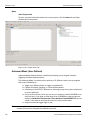
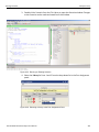
Using the Software
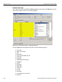
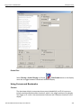
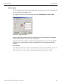
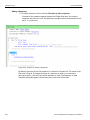
The SierraFC M164 application has protocol analysis software to capture data, trigger on Events, and save. Easy Mode allows standard Trigger and Data capture. Advanced Mode (see figure below) allows you to program custom triggering in and out, capturing, state jumps, and timers. (See “Protocol Analysis” on page 33.)
28 SierraFC M164 Protocol Analyzer User Manual
Teledyne LeCroy
Using the Software
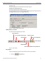
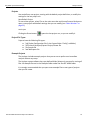
Easy, switch to Advanced Mode
Figure 1.18: Easy/Advanced Mode Toggle Button
SierraFC M164 Protocol Analyzer User Manual
29
Teledyne LeCroy
Protocol Analyzer
Protocol Analyzer
To use the software for protocol analysis (see on page 29), first select File > Protocol Analyzer for a new project or File > Open an existing protocol analysis .fcc file. (See “Protocol Analysis” on page 33.) You can also open a .fcs example file. Example files are in the Examples folder. You can also use Project Setup > Last Protocol Analyzer.
In Easy Mode, on the Capture tab, select to capture Everything or Pattern. For Pattern, select a Pattern. You can exclude patterns and frames. You can do this by dragging patterns from the Patterns Library pane into the Active pane. You can use different patterns for pre‐trigger and post‐trigger.
In Easy Mode, on the Trigger tab, select the trigger type. For Pattern, select the pattern.
In Easy Mode, on the Settings tab, select trigger position and memory use. Change the Analyzer settings if necessary. Change the port Speed if necessary.
Use Advanced Mode only after you become familiar with the hardware and software and have special needs. To start working with the protocol analyzer and software. See “Protocol Analysis” on page 33.
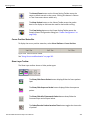
Viewing Captured Data
After data capture, the captured data is in the Viewer, see “Display Manipulation” on page 181. You can display the same data in:
Spreadsheet View: Shows Protocol Fields and Frames by time.
Frame Inspector View: Shows detail information about packet highlighted in Spreadsheet or Packet views.
Packet View: Shows hierarchical view of frames, sequences and exchanges.
Text View: Shows transaction frames, grouped in columns by port.
Statistical Report View
You can do the following:
30 Show or hide fields and ports, change port names, and change data format.
Show the layers and channels using their toolbars.
Decode using the Decode toolbar.
Quick View shortens the time to view a recent trace (see “Quick View” on page 184)
Quick Search and Quick Filter (“Quick Search” on page 239 and “Quick Filter‐
ing” on page 231).
Search and Filter in Advanced mode (see “Search Setup in Advanced Mode” on page 240 and “Filter Setup in Advanced Mode” on page 232).
SierraFC M164 Protocol Analyzer User Manual
Teledyne LeCroy
Protocol Analyzer
Configuration
For special work, you can use the Configuration menu to configure Port Alias, External Trig Setting, Software Settings, and Input/Output Signals. (“Display Manipulation” on page 181.)
Port Status
You can display an overview of the active ports by clicking the buttons at the bottom right of the main window (see “Port Status” on page 202).
Statistical Reports
You can generate statistics for all transports, commands, primitives, addresses, lanes, and errors (see “Statistical Report” on page 209).
InFusion
The Teledyne LeCroy InFusion™ Error Injector and Traffic Modifier is an error injector and traffic modification tool that allows you to verify real‐world fault handling for SierraFC systems (see “FC InFusion” on page 255).
CrossSync Control Panel
The CrossSync Control Panel allows you to select analyzers for synchronization and manage the recording process. It supports a wide combination of Teledyne LeCroy’s flagship analyzers including PCI Express Gen 1, Gen 2 and Gen 3; USB 2.0 and 3.0; Serial ATA (SATA) 1.5, 3 and 6Gbps; Serial Attached SCSI (SAS) 6Gbps and Fibre Channel 1. 2, 4 and 8Gbps systems. CrossSync is Teledyne LeCroy’s analyzer synchronization solution that enables time‐
aligned display of protocol traffic from multiple daisy‐chained analyzers showing packet traffic from multiple high‐speed serial busses. A lightweight software control panel allows users to select analyzers for synchronization and manage the recording process. Captured traffic is displayed using the latest analyzer software (in separate windows) with all the protocol specific search and reporting features.
Captured packets are displayed in separate windows that share a common time scale. Navigating the traffic in either direction will scroll to the same timestamp in a synchronized window. When using the CrossSync option, users can access the full complement of analysis capabilities available within the individual Teledyne LeCroy software. Search, reporting, and decoding all operate normally (see “CrossSync Control Panel” on page 40). This feature is available with the Teledyne LeCroy SierraFC Fibre channel Protocol Suite application.
SierraFC M164 Protocol Analyzer User Manual
31
Teledyne LeCroy
32 Protocol Analyzer
SierraFC M164 Protocol Analyzer User Manual
Chapter 2
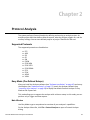
Protocol Analysis
The system performs Protocol Analysis by defining and running an analysis project. An analysis project definition defines what to capture, what the analyzer triggers on, and the memory settings. You can save defined projects as project *.fcc files for later use.
Supported Protocols
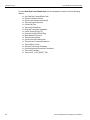
The supported protocols are listed below:
FCP
ARB ELS
GS
SW
FICON
FCAE‐ASM
FCAE‐1553
FCAE‐RDMA
FCVI
FCAV
ADVB
VSAN
Easy Mode (Pre-Defined Setups)
After you install the Analyzer software (see “Software Installation” on page 16) and set up the Analyzer (see “Hardware Setup” on page 17), launch the Analyzer software (see “Launching Your Analyzer” on page 28) to display the default Protocol Analyzer in Easy Mode at the Capture tab.
This mode allows you to operate the analyzer with minimum setup. In this mode, you can perform only a Trigger and Data capture.
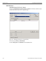
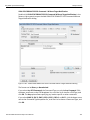
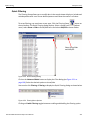
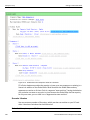
Main Window
Use Easy Mode to get a comprehensive overview of your analyzer’s capabilities:
On the Analyzer Menu Bar, click File > Protocol Analyzer to open a Protocol Analyzer dialog.
SierraFC M164 Protocol Analyzer User Manual
33
Teledyne LeCroy
Easy Mode (Pre‐Defined Setups)
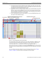
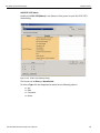
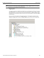
Project Overview Pane
What analyzer triggers on
Capture Memory Settings
Collapse All Button: hides
details in Project Overview
Expand All Button: shows
details in Project Overview
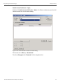
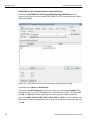
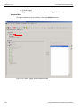
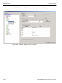
Figure 2.1: Protocol Analysis Project Dialog
The New Project dialog opens with default settings to capture Everything on the bus and to Trigger On on Snapshot. (The analyzer captures everything immediately without triggering on anything in particular).
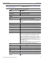
Analyzer Settings
Buffer Size and Segments
The Analyzer Settings tab has the Recording Buffer pane where you can set Number of Segments and the Segment Size. (See “Buffer Size and Segments” on page 172.)
Trigger Position
You can set the trigger position in the captured buffer as a percentage of the segment size. Trigger point of 0% means the trigger point will be on the first packet in the buffer. (See “Trigger Position” on page 172.)
34 SierraFC M164 Protocol Analyzer User Manual
Teledyne LeCroy
Easy Mode (Pre‐Defined Setups)
Auto Run
Checking the Auto Run option allows you to specify the number of concurrent runs that will be automatically carried out. (See “Auto Run” on page 172.)
Training Signal Pack Mode
This options provides two modes for training signals.
Unpacked
Packed
Last Captured Trace File
Browse to the location to upload the last captured trace file. Alternatively check the box to use the Upload Manager.
Analyzer Settings
You can enable the ports, set the port speed and disable descrambling.
Disabling a port can be used to save recording buffer space. A disabled port can still trigger the analyzer.
Auto Speed is the default port speed selection. It will automatically detect and display the line speed. In rare cases (such as debugging speed negotiation), it might be desired to set the analyzers speed manually. Note, that when the speed is set manually, traffic at different speeds will not be captured correctly.
You can disable descrambling.
Set Protocol Error Detection
You can select which Protocol Errors the analyzer will show and which will be ignored.
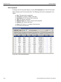
Project Overview
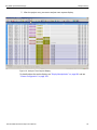
The Project Overview on the right side of the main window displays a comprehensive tree structured overview of the project. The project tree shows what to capture, on what the analyzer triggers, and the capture memory settings.
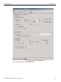
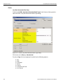
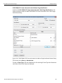
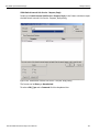
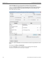
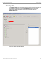
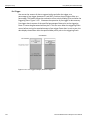
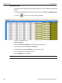
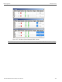
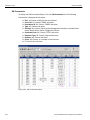
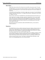
Capture Tab
The Capture tab allows you to set the parameters for capturing patterns. The Capture dialog box opens with default settings to capture Everything on the bus. The analyzer captures everything immediately without triggering on anything in particular.
You can drag and drop patterns from the Patterns Library pane into the Active Pane. You can select the pattern and use the Add and Remove arrows to move patterns between the Patterns Library and the Active pane. You can copy and sort the patterns.
Note: Capturing a 16GB trace requires you to capture the traffic with both ports (P1, P2 & P3, P4), otherwise, only an 8GB trace is captured.
Truncate Payload
Check this option to truncate payload after x‐number of Dword(s). SierraFC M164 Protocol Analyzer User Manual
35
Teledyne LeCroy
Easy Mode (Pre‐Defined Setups)
Include and Exclude
arrows
Figure 2.2: Capture Dialog
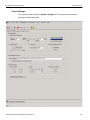
Parameters
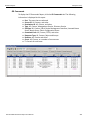
The Capture tab has the following parameters. See Figure 2.3 on page 37.
Exclude Idle
Check this to exclude Idles from the data capture.
Exclude RRDY
Check this to exclude RRDY primitives from the data capture.
Exclude Training Pattern
Check this to exclude Training Pattern primitives from the data capture.
Exclude ARBff
Check this to exclude ARBff primitives from the data capture.
Exclude NOS
Check this to exclude NOS primitives from the data capture.
36 SierraFC M164 Protocol Analyzer User Manual
Easy Mode (Pre‐Defined Setups)
Teledyne LeCroy
Exclude VC_RDY
Check this to exclude VC_RDY primitives from the data capture.
Exclude traffic till both ports are up
Check this to exclude traffic till both ports are up.
Use separate patterns for Pre‐ and Post‐triggers captures replaces the Capture tab with a Pre‐Trigger Capture tab and a Post‐Trigger Capture tab.
Figure 2.3: Protocol Analysis Capture Dialog
Software Menus and Toolbar
The software has the following main toolbar. Open Sample File
Run Last Open Capture Project
Upload Manager
Switch to Jammer
Show Port Configuration
Toolbar Options
Stop Hardware
Abort Capturing Without Saving Sample File
Figure 2.4: Main Toolbar
Run Hardware
To get an immediate overview of the bus traffic to and from your Analyzer:
1. Click the SierraFC M164 Protocol Analyzer User Manual
Record button.
37
Teledyne LeCroy
Easy Mode (Pre‐Defined Setups)
2. The analyzer begins filling the defined memory buffer with traffic on the bus. After the traffic fills the memory buffer, the traffic is uploaded to the viewer and all views are displayed, except the Statistical Report View. 3. Spreadsheet View is the default display. However, you can view results in any of the different views by selecting View on the menu bar and choosing the desired View. Note: the software remembers the last view (or views combination) used, and will automatically use that next time it is launched.
4. How to add additional buttons need to add to 4. You can add additional keys to the view panel. Please follow the steps:
X,Y,T Cursors
Relative time display (Between two sequential
packets on the same layer and port)
Quick Search
Quick View
Show/Hide Protocol Layers
Show/Hide port data
Data direction arrows
Figure 2.5: Typical Spreadsheet View Results Display
The results display shows each transaction for every layer identified in a different color and the data direction identified with data direction arrows. Upstream traffic has an arrow from right to left:. Downstream traffic has an arrow left to right: .
You can hide any layer by clicking the corresponding Show/Hide button on the menu bar. The system retains all captured data, but the display has only some data layers for simpler viewing.
You can configure the viewer display for test and viewing preferences (see “Viewer Display” on page 181 for details about configuring the viewer display).
38 SierraFC M164 Protocol Analyzer User Manual
Teledyne LeCroy
Easy Mode (Pre‐Defined Setups)
The Analysis Project dialog offers you a comprehensive set of choices to create a trigger and capture project satisfying some specific need. You can set the Analyzer to:
Capture specific patterns (see “Patterns and Data Capture Setup” on page 44).
Capture different patterns pre‐ and post‐trigger (see “Patterns and Data Capture Setup” on page 44).
Exclude parameters from capture (see “Patterns and Data Capture Setup” on page 44).
Trigger on a pattern or sequence of patterns (see “Trigger Setup” on page 149).
Configure trace capture memory (see “Project Settings” on page 180).
Select file to save trace capture in memory (see “Project Settings” on page 180).
Include a project note (see “Notes” on page 180).
Saving a Trace Capture
You can save a Trace Capture for review at a later time using the Save As dialog. Figure 2.6: Save As Dialog
SierraFC M164 Protocol Analyzer User Manual
39
Teledyne LeCroy
Easy Mode (Pre‐Defined Setups)
You can limit the range of the saved file. You can save:
All Traces
A range between selected cursors
A range between selected levels of decoding. The levels allowed are dependent on the traffic in the trace. A trace with only Switch traffic might have the follow‐
ing levels available: ELS Cmd, Frame, GS Cmd, Sequence and SW Cmd, whereas a read‐write trace might have Frame, SCSI Cmd and Sequence available.
A range between selected timestamps. Specify the time format from the drop‐
down list.
Save Filtered Sample checkbox saves a trace file without filtered data.
CrossSync Control Panel
The CrossSync Control Panel allows you to select analyzers for synchronization and manage the recording process.
Launching the CrossSync Control Panel
To launch CrossSync from the FC Protocol Suite software application, select the ‘Launch CrossSync Control Panel ‘entry in the ‘Project Setup’ menu (see the screen below). Or, you can launch CrossSync from the ‘Start’ menu.
Figure 2.7: Launching CrossSync from the SierraFC M164 Protocol Suite Application
Please refer to the CrossSync Control Panel User Manual for more information.
40 SierraFC M164 Protocol Analyzer User Manual
Teledyne LeCroy
Easy Mode (Pre‐Defined Setups)
Projects
You can define a new project, starting with the default project definition, or modify the settings for the last project run.
New Default Project
To start a New project, select File on the main menu bar and choose Protocol Analyzer to open a new project with default settings that you can modify (see “Main Window” on page 33).
Last Project
Clicking the Green button opens the last project run, so you can modify it.
Project File Types
Projects have the following file types:
*.cfg Display Configuration file (in the System folder “Config” subfolder)
*.fcc Protocol Analyzer/Capture Project/Viewer file
*.fcs Sample file
*.wsf Workspace file
Example Projects
The Analyzer includes example projects that you can use to perform an immediate analysis without any setup.
The Analyzer system software has a pre‐defined folder (directory) structure for storing all files. All example files are in the Examples folder under the SierraFC M164 folder.
It is strongly recommended that you open some example files to see types of projects that you can create.
SierraFC M164 Protocol Analyzer User Manual
41
Teledyne LeCroy
Easy Mode (Pre‐Defined Setups)
Run an Example Analysis Project
To run an example project:
1. Select File > Open.
2. Locate example analysis projects by looking in the Examples folder. Examples are available for AdvanceCaptr, EasyCaptr, and Samples.
3. In the Samples folder, choose an example *.fcs file and click Open to display the example project dialog.
Figure 2.8: Open File Dialog
4. Click the Record button to execute the pre‐defined example.
42 SierraFC M164 Protocol Analyzer User Manual
Easy Mode (Pre‐Defined Setups)
Teledyne LeCroy
5. After the project runs, you see an analyzer trace capture display. Figure 2.9: Analyzer Trace Capture Display
For details about the results display, see “Display Manipulation” on page 181 and see “Viewer Configuration” on page 244.
SierraFC M164 Protocol Analyzer User Manual
43
Teledyne LeCroy
Easy Mode (Pre‐Defined Setups)
Patterns and Data Capture Setup
You can refine data capture by choosing Pattern and then selecting specific patterns for capture. Additionally, you can define a different set of patterns to capture after trigger.
To define specific patterns for capture, click the Pattern button to display the Capture tab for Pattern (see Figure 2.10 on page 44. You can drag and drop patterns from the Patterns Library pane into the Active Pane. You can select the pattern and use the Add and Remove arrows to move patterns between the Patterns Library and the Active pane. You can also copy and sort patterns
Add and
Remove
arrows
Figure 2.10: Choosing Capture Patterns
44 SierraFC M164 Protocol Analyzer User Manual
Easy Mode (Pre‐Defined Setups)
Teledyne LeCroy
Choose a Parameter
To choose a parameter for capture from any of these categories, highlight the category in the parameter window and click the +>> button to add the selection. You can also drag and drop a pattern. This opens selection dialogs for each of the categories displaying all of the parameters for that category. All patterns added appear in the Project Overview.
Include Patterns
This is the default selection. Check this box to allow for the capture of the patterns that have been added to the Project Overview. When you Include Patterns, only those patterns will be recorded, thus saving buffer space and emphasizing only what the user needs. However, to get proper context, you would typically need to include a lot of Patterns. To Exclude only unwanted Patterns is another option.
Exclude Patterns
Check this box to allow for the capture of everything except the patterns that have been added to the Project Overview. When you check the Exclude Patterns box, the Ordered Set category appears in the Pattern List, and the Exclude Idle item appears in the Project Overview under the Capture (Exclude) branch. SierraFC M164 Protocol Analyzer User Manual
45
Teledyne LeCroy
Easy Mode (Pre‐Defined Setups)
Figure 2.11: Exclude Patterns Checked
To remove an item from capture, highlight it in the Project Overview and click the ‐<< button.
46 SierraFC M164 Protocol Analyzer User Manual
Easy Mode (Pre‐Defined Setups)
Teledyne LeCroy
Pre- and Post Trigger Data Capture
You can define one set of patterns for capture prior to the occurrence of a trigger and another set of patterns for capture after the occurrence of a trigger. The selection and setup procedure is the same for both Pre‐Trigger capture and Post‐Trigger capture. Check Use separate patterns for Pre‐ and Post‐trigger captures to enable the Pre‐Trigger Capture and Post‐Trigger Capture tabs (instead of only the Capture tab).
Check box for Pre- and
Post trigger captures
Figure 2.12: Pre-Trigger and Post-Trigger Capture Dialog Enabled
Defining Patterns
To select an item for capture, either highlight the category and click the +>> button, or double‐click the category, to open a corresponding definition dialog. You can define patterns for specific ports by checking or unchecking the Port ID.
SierraFC M164 Protocol Analyzer User Manual
47
Teledyne LeCroy
Easy Mode (Pre‐Defined Setups)
Basic Patterns
Connect/Disconnect
Double‐click Connect/Disconnect to open the Add Connect Disconnect Pattern dialog.
Figure 2.13: Connect Disconnect Pattern Dialog
Check Connect and/or Disconnect.
48 SierraFC M164 Protocol Analyzer User Manual
Easy Mode (Pre‐Defined Setups)
Teledyne LeCroy
Ordered Set Double‐click Ordered Set to open the Add Ordered Set Pattern dialog. Figure 2.14: Ordered Set Pattern Dialog
To select an Ordered Set, click the dropdown list. You can choose NOT to trigger on anything that is NOT the defined pattern. You can choose Frame Delimiters, Primitive Signals, or Primitive Sequences. Note: The Symbol pattern is only available on the Trigger tab, and when using the Ordered Set pattern, only the Exclude option is available.
SierraFC M164 Protocol Analyzer User Manual
49
Teledyne LeCroy
Easy Mode (Pre‐Defined Setups)
Basic Link Service
Double‐click Basic Link Service in the Pattern window to open the Add Basic Link Service Pattern dialog.
Figure 2.15: Basic Link Service Pattern Dialog
The format can be Binary or Hexadecimal.
To select a Basic Link Service, click the dropdown list.
50 SierraFC M164 Protocol Analyzer User Manual
Easy Mode (Pre‐Defined Setups)
Teledyne LeCroy
Link Control Frame
Double‐click Link Control Frame in the Pattern window to open the Add Link Control Frame Pattern dialog.
Figure 2.16: Link Control Frame Pattern Dialog
The format can be Binary or Hexadecimal.
To select a Link Control Frame, click the dropdown list.
Symbol 16G
The Symbol 16G cannot be added as a Capture Pattern. Training Sequence
The Training Sequence cannot be added as a Capture Pattern. Capture (Filter Out)
Exclude Training Sequence.
SierraFC M164 Protocol Analyzer User Manual
51
Teledyne LeCroy
Easy Mode (Pre‐Defined Setups)
FCP Patterns
FCP SCSI Command
Double‐click FCP SCSI Command in the Pattern window to open the Add FCP SCSI Command Pattern dialog.
Hover over commands to display tooltips
Figure 2.17: FCP SCSI Command Pattern Dialog
The format can be Binary or Hexadecimal.
If you select Any SCSI Command, the Command Type can only be Any Command. Click the down arrow next to the CDB dropdown list, scroll the list to choose a CDB Type, and click OK. The Any option allows specifying any vendor‐specific or other command. If you select MMC‐6, SBC‐3, SMC‐3, SPC‐4, SSC‐2, OSD‐2, or ADC‐3, click the down arrow next to the Command Type dropdown list, scroll the list to choose a Command Type, and click OK.
52 SierraFC M164 Protocol Analyzer User Manual
Easy Mode (Pre‐Defined Setups)
Teledyne LeCroy
FCP Frame Information Unit
Double‐click FCP Frame Information Unit in the Pattern window to open the Add FCP Frame Information Unit Pattern dialog.
Figure 2.18: FCP Frame Information Unit Pattern Dialog
The format can be Binary or Hexadecimal.
To select a Frame Type, click the dropdown list. On selecting a Frame Type the Parameters and Value of that Frame Type are displayed.
SierraFC M164 Protocol Analyzer User Manual
53
Teledyne LeCroy
Easy Mode (Pre‐Defined Setups)
SCSI Command Status
Double‐click SCSI Command Status in the Pattern window to open the Add SCSI Command Status Pattern dialog.
Figure 2.19: SCSI Command Status Pattern Dialog
You can capture on Status Only or Sense Key/Response Code. Click on Status Only to display all the states that are available. Click on the Sense Key/Response Code to display all the Format and Sense Keys.
RSP_CODE: It is selected by default. You can click on the dropdown list to select more options.
54 SierraFC M164 Protocol Analyzer User Manual
Easy Mode (Pre‐Defined Setups)
Teledyne LeCroy
FCP Task Management
Double‐click FCP Task Management in the Pattern window to open the Add FCP Task Management Pattern dialog.
Figure 2.20: FCP Task Management Pattern Dialog
The format can be Binary or Hexadecimal.
To select a Function, click the dropdown list.
SierraFC M164 Protocol Analyzer User Manual
55
Teledyne LeCroy
Easy Mode (Pre‐Defined Setups)
ARB Patterns
ARB Loop Initialization
Double‐click ARB Loop Initialization in the Pattern window to open the Add ARB Loop Initialization Pattern dialog.
Figure 2.21: ARB Loop Initialization Pattern Dialog
The format can be Binary or Hexadecimal.
To select a Loop Init ID, click the dropdown list.
56 SierraFC M164 Protocol Analyzer User Manual
Easy Mode (Pre‐Defined Setups)
Teledyne LeCroy
ELS Patterns
Extended Link Service ‐ Request
Double‐click Extended Link Service ‐ Request in the Pattern window to open the Add Extended Link Service Pattern dialog.
Figure 2.22: Extended Link Service - Request Pattern Dialog
The format can be Binary or Hexadecimal.
To select an ELS_Type, click the dropdown list.
SierraFC M164 Protocol Analyzer User Manual
57
Teledyne LeCroy
Easy Mode (Pre‐Defined Setups)
Extended Link Service ‐ Request, Reply
Double‐click Extended Link Service ‐ Request, Reply in the Pattern window to open the Add Extended Link Service Pattern dialog.
Figure 2.23: Add Extended Link Service - Request, Reply Pattern Dialog
The format can be Binary or Hexadecimal.
To select an ELS_Type, click the dropdown list.
58 SierraFC M164 Protocol Analyzer User Manual
Easy Mode (Pre‐Defined Setups)
Teledyne LeCroy
Extended Link Service ‐ Reply
Double‐click Extended Link Service ‐ Reply in the Pattern window to open the Add Extended Link Service Pattern dialog.
Figure 2.24: Extended Link Service - Reply Pattern Dialog
The format can be Binary or Hexadecimal.
To select an ELS_Type, click the dropdown list.
SierraFC M164 Protocol Analyzer User Manual
59
Teledyne LeCroy
Easy Mode (Pre‐Defined Setups)
GS Patterns
Generic Link Service ‐ Request
Double‐click Generic Link Service ‐ Request in the Pattern window to open the Add Generic Link Service Pattern dialog.
Figure 2.25: Generic Link Service Pattern Dialog
The format can be Binary or Hexadecimal.
Click the dropdown lists to select a GS_Type, GS_Subtype, Command Type, and Command.
60 SierraFC M164 Protocol Analyzer User Manual
Easy Mode (Pre‐Defined Setups)
Teledyne LeCroy
Generic Link Service ‐ Request, Reply
Double‐click Generic Link Service ‐ Request, Reply in the Pattern window to open the Add Generic Link Service Pattern dialog.
Figure 2.26: Generic Link Service-Request, Reply Pattern Dialog
The format can be Binary or Hexadecimal.
Click the dropdown lists to select a GS_Type, GS_Subtype, Command Type, and Command.
SierraFC M164 Protocol Analyzer User Manual
61
Teledyne LeCroy
Easy Mode (Pre‐Defined Setups)
Generic Link Service ‐ Reply
Double‐click Generic Link Service ‐ Reply in the Pattern window to open the Add Generic Link Service Pattern dialog.
Figure 2.27: Generic Link Service Pattern Dialog
The format can be Binary or Hexadecimal.
Click the dropdown lists to select a GS_Type, GS_Subtype, Command Type, and Command.
62 SierraFC M164 Protocol Analyzer User Manual
Easy Mode (Pre‐Defined Setups)
Teledyne LeCroy
SW Patterns
Switch Internal Link Service ‐ Request
Double‐click Switch Internal Link Service ‐ Request in the Pattern window to open the Add Switch Internal Link Service Pattern dialog.
Figure 2.28: Switch Internal Link Service Pattern Dialog
The format can be Binary or Hexadecimal.
To select a SW_Type and a Command, click the dropdown lists.
SierraFC M164 Protocol Analyzer User Manual
63
Teledyne LeCroy
Easy Mode (Pre‐Defined Setups)
Switch Internal Link Service ‐ Request, Reply
Double‐click Switch Internal Link Service ‐ Request, Reply in the Pattern window to open the Add Switch Internal Link Service Pattern dialog.
Figure 2.29: Switch Internal Link Service-Request, Reply Pattern Dialog
The format can be Binary or Hexadecimal.
To select a SW_Type and a Command click the dropdown lists.
64 SierraFC M164 Protocol Analyzer User Manual
Easy Mode (Pre‐Defined Setups)
Teledyne LeCroy
Switch Internal Link Service ‐ Reply
Double‐click Switch Internal Link Service ‐ Reply in the Pattern window to open the Add Switch Internal Link Service Pattern dialog.
Figure 2.30: Switch Internal Link Service Pattern Dialog
The format can be Binary or Hexadecimal.
To select a SW_Type and a Command click the dropdown lists.
SierraFC M164 Protocol Analyzer User Manual
65
Teledyne LeCroy
Easy Mode (Pre‐Defined Setups)
FICON
Any Data Information Block Type
Double‐click FICON ‐ (Any Data Information Block Type) in the Patterns Library panel to open the FICON ‐ Any Data Information Block Type dialog.
Figure 2.31: FICON - (Any Data Information Block Type) Dialog
The format can be Binary or Hexadecimal.
To select a Type click the dropdown list which has the following options:
66 Any
Data
Command Status
Control
Command and Data
Link Control
SierraFC M164 Protocol Analyzer User Manual
Teledyne LeCroy
Easy Mode (Pre‐Defined Setups)
Add FICON Data
Double‐click FICON(Data) in the Patterns Library panel to open the FICON Data dialog.
Figure 2.32: FICON (Data) Dialog
The format can be Binary or Hexadecimal.
To select a Type click the dropdown list which has the following options:
Any
Data
Command Status
Control
Command and Data
Link Control
SierraFC M164 Protocol Analyzer User Manual
67
Teledyne LeCroy
Easy Mode (Pre‐Defined Setups)
Add FICON Command
Double‐click FICON(Command) in the Patterns Library panel to open the FICON Command dialog.
Figure 2.33: FICON (Command) Dialog
The format can be Binary or Hexadecimal.
To select a Type click the dropdown list which has the following options:
68 Any
Data
Command Status
Control
Command and Data
Link Control
SierraFC M164 Protocol Analyzer User Manual
Teledyne LeCroy
Easy Mode (Pre‐Defined Setups)
FICON[Command]‐CCW Command Type
The FICON[Command] has an additional CCW Command Type dropdown menu under the Value pane on the right of the dialog as shown in the following figure.
Figure 2.34: FICON[Command] - CCW Command Type Dialog
To select CCW Command Type click the dropdown list which has the following options:
Any CCW Command Type
Sense Read‐Backward Write Read
Control
SierraFC M164 Protocol Analyzer User Manual
69
Teledyne LeCroy
Easy Mode (Pre‐Defined Setups)
Add FICON Status
Double‐click FICON(Status) in the Patterns Library panel to open the FICON Status dialog.
Figure 2.35: FICON (Status) Dialog
The format can be Binary or Hexadecimal.
To select a Type click the dropdown list which has the following options:
70 Any
Data
Command Status
Control
Command and Data
Link Control
SierraFC M164 Protocol Analyzer User Manual
Teledyne LeCroy
Easy Mode (Pre‐Defined Setups)
FICON[Status]‐ Flag‐Field Code
The FICON[Status] has an additional Flag‐Field Code dropdown menu under the Value pane on the right of the dialog as shown in the following figure.
Figure 2.36: FICON[Status] - Any Flag-Field Code Dialog
To select Flag‐Field Code click the dropdown list which has the following options:
Any Flag‐Field Code
No Function
Queueing Information Valid
Resetting Event
SierraFC M164 Protocol Analyzer User Manual
71
Teledyne LeCroy
Easy Mode (Pre‐Defined Setups)
FICON[Status]‐Status Byte
The FICON[Status] has an additional Status Byte dropdown menu under the Value pane on the right of the dialog as shown in the following figure.
Figure 2.37: FICON[Status] - Status Byte Dialog
To select Status Byte click the dropdown list which has the following options:
72 Any Status Byte
Attention
Status Modifier
Control Unit End
Busy
Channel End
Device End
Unit Check
Unit Exception
SierraFC M164 Protocol Analyzer User Manual
Teledyne LeCroy
Easy Mode (Pre‐Defined Setups)
Add FICON Control
Double‐click FICON(Control) in the Patterns Library panel to open the FICON Control dialog.
Figure 2.38: FICON (Control) Dialog
The format can be Binary or Hexadecimal.
To select a Type click the dropdown list which has the following options:
Any
Data
Command Status
Control
Command and Data
Link Control
SierraFC M164 Protocol Analyzer User Manual
73
Teledyne LeCroy
Easy Mode (Pre‐Defined Setups)
FICON[Control]‐Control Function
The FICON[Control] has an additional Control Function dropdown menu under the Value pane on the right of the dialog as shown in the following figure.
Figure 2.39: FICON[Control] - Control Function Dialog
To select Control Function click the dropdown list which has the following options:
74 Any Control Function
Control End
Command Response
Stack Status
cancel
System Request
Selective Reset
Request Status
Device Level Exception
Status Accepted
Device Level Acknowledgement
Purge Path
Purge Path Response
SierraFC M164 Protocol Analyzer User Manual
Teledyne LeCroy
Easy Mode (Pre‐Defined Setups)
Add FICON Command‐Data
Double‐click FICON(Command‐Data) in the Patterns Library panel to open the FICON Command Data dialog.
Figure 2.40: FICON (Command Data) Dialog
The format can be Binary or Hexadecimal.
To select a Type click the dropdown list which has the following options:
Any
Data
Command Status
Control
Command and Data
Link Control
SierraFC M164 Protocol Analyzer User Manual
75
Teledyne LeCroy
Easy Mode (Pre‐Defined Setups)
FICON[Command]‐CCW Command Type
The FICON[Command‐Data] has an additional CCW Command Type dropdown menu under the Value pane on the right of the dialog as shown in the following figure.
Figure 2.41: FICON[Command-Data] - CCW Command Type Dialog
To select CCW Command Type click the dropdown list which has the following options:
76 Any CCW Command Type
Sense Read‐Backward Write Read
Control
SierraFC M164 Protocol Analyzer User Manual
Teledyne LeCroy
Easy Mode (Pre‐Defined Setups)
Add FICON Link‐Control
Double‐click FICON(Link‐Control) in the Patterns Library panel to open the FICON Link Control dialog.
Figure 2.42: FICON (Link-Control) Dialog
The format can be Binary or Hexadecimal.
To select a Type click the dropdown list which has the following options:
Any
Data
Command Status
Control
Command and Data
Link Control
SierraFC M164 Protocol Analyzer User Manual
77
Teledyne LeCroy
Easy Mode (Pre‐Defined Setups)
FICON[Link Control]‐Link Control Function
The FICON[Link Control] has an additional Link Control Function dropdown menu under the Value pane on the right of the dialog as shown in the following figure.
Figure 2.43: FICON[Link Control] - Link Control Function Dialog
To select Link Control Function click the dropdown list which has the following options:
78 Any Link Control Function
Establish Logical Path
Remove Logical Path
Test Initialization
Logical Path Established
Logical Path Removed
Test Initialization Result
Link‐Level Reject
Link‐Level Busy
Link‐Level Acknowledgement
SierraFC M164 Protocol Analyzer User Manual
Easy Mode (Pre‐Defined Setups)
Teledyne LeCroy
FCAE
FCAE‐ASM Double‐click FCAE‐ASM in the Patterns Library panel to open the FCAE‐ASM dialog to add any Type of FCAE‐ASM.
Figure 2.44: FCAE-ASM Dialog
The format can be Binary or Hexadecimal.
SierraFC M164 Protocol Analyzer User Manual
79
Teledyne LeCroy
Easy Mode (Pre‐Defined Setups)
FCAE‐1553 Any Double‐click FCAE‐1553(Any) in the Patterns Library panel to open the FCAE‐1553 dialog to add any Type of FCAE‐1553.
Figure 2.45: FCAE-1553 (Any) Dialog
The format can be Binary or Hexadecimal.
To select a Type click the dropdown list which has the following options:
80 Any
Data
Command Status
SierraFC M164 Protocol Analyzer User Manual
Teledyne LeCroy
Easy Mode (Pre‐Defined Setups)
Add FCAE‐1553 Data
Double‐click FCAE‐1553(Data) in the Patterns Library panel to open the FCAE‐1553 Data dialog.
Figure 2.46: FCAE-1553(Data) Dialog
The format can be Binary or Hexadecimal.
To select a Type click the dropdown list which has the following options:
Any
Data
Command Status
SierraFC M164 Protocol Analyzer User Manual
81
Teledyne LeCroy
Easy Mode (Pre‐Defined Setups)
Add FCAE‐1553 Command
Double‐click FCAE‐1553(Command) in the Patterns Library panel to open the FCAE‐1553 Command dialog.
Figure 2.47: FCAE-1553 (Command) Dialog
The format can be Binary or Hexadecimal.
To select a Type click the dropdown list which has the following options:
82 Any
Data
Command Status
SierraFC M164 Protocol Analyzer User Manual
Easy Mode (Pre‐Defined Setups)
Teledyne LeCroy
FCAE‐1553[Command]‐Data Byte Count /Mode Code
The FCAE‐1553[Command] has an additional Data Byte Count /Mode Code dropdown menu under the Value pane on the right of the dialog as shown in Figure 2.46. The dropdown menu items could be truncated, hover the mouse over the option to see the full menu option (see the following figure).
Figure 2.48: Hover the Mouse to see the Full Menu Option
Figure 2.49: FCAE-1553[Command]- Data Byte Count/Mode Code Dialog
SierraFC M164 Protocol Analyzer User Manual
83
Teledyne LeCroy
Easy Mode (Pre‐Defined Setups)
To select Data Byte Count/Mode Code click the dropdown list which has the following options:
84 Any Data Byte Count/Mode Code
Dynamic Network Control
Synchronize (without data word)
Transmit Status Sequence
Initiate Self‐Test
Transmitter Shutdown
Override Transmitter shutdown
Inhibit Terminal Flag (T/F)
Override Inhibit Terminal Flag
Reset Network Terminal Transmit Vector Word
Synchronize (with data word)
Transmit Last Command Sequence
Transmit Built In test
Selected Transmitter Shutdown
Override Selected Transmitter Shutdown
Transmit RT Address
Transmit NT_C‐D/S_BURST_TOV
SierraFC M164 Protocol Analyzer User Manual
Teledyne LeCroy
Easy Mode (Pre‐Defined Setups)
Add FCAE‐1553 Status
Double‐click FCAE‐1553(Status) in the Patterns Library panel to open the FCAE‐1553 Status dialog.
Figure 2.50: FCAE-1553 (Status) Dialog
The format can be Binary or Hexadecimal.
To select a Type click the dropdown list which has the following options:
Any
Data
Command Status
SierraFC M164 Protocol Analyzer User Manual
85
Teledyne LeCroy
Easy Mode (Pre‐Defined Setups)
FCAE‐FCP SCSI Command ‐ RDMA With Target Notification
Double‐click FCAE RDMA FCP SCSI Command‐With Target Notification in the Patterns Library panel to open thee Add FCAE RDMA FCP SCSI Command‐With Target Notification dialog.
Figure 2.51: FCAE FCP-RDMA SCSI Command With Target Notification Dialog
The format can be Binary or Hexadecimal.
If you select Any SCSI Command, the Command Type can only be Any Command. Click the down arrow next to the CDB dropdown list, scroll the list to choose a CDB Type, and click OK. The Any option allows specifying any vendor‐specific or other command. If you select MMC‐6, SBC‐3, SMC‐3, SPC‐4, SSC‐2, OSD‐2, or ADC‐3, click the down arrow next to the Command Type dropdown list, scroll the list to choose a Command Type, and click OK.
86 SierraFC M164 Protocol Analyzer User Manual
Easy Mode (Pre‐Defined Setups)
Teledyne LeCroy
FCAE RDMA FCP Command Frame Information Unit With Target Notification
Double‐click FCAE RDMA FCP Command Frame Information Unit ‐With Target Notification in the Pattern window to open the Add FCAE RDMA FCP Command Frame Information Unit With Target Notification dialog.
Figure 2.52: FCAE RDMA FCP Command Frame Information Unit -With Target Notification
Pattern Dialog
The format can be Binary or Hexadecimal.
To select a Frame Type, click the dropdown list. On selecting a Frame Type the Parameters and Value of that Frame Type are displayed.
SierraFC M164 Protocol Analyzer User Manual
87
Teledyne LeCroy
Easy Mode (Pre‐Defined Setups)
FCAE‐RDMA FCP SCSI Command Without Target Notification
Double‐click FCAE RDMA FCP SCSI Command‐Without Target Notification in the Patterns Library panel to open the Add FCAE RDMA FCP SCSI Command‐Without Target Notification dialog.
Figure 2.53: FCAE RDMA FCP SCSI Command Without Target Notification Dialog
The format can be Binary or Hexadecimal.
If you select Any SCSI Command, the Command Type can only be Any Command. Click the down arrow next to the CDB dropdown list, scroll the list to choose a CDB Type, and click OK. The Any option allows specifying any vendor‐specific or other command. If you select MMC‐6, SBC‐3, SMC‐3, SPC‐4, SSC‐2, OSD‐2, or ADC‐3, click the down arrow next to the Command Type dropdown list, scroll the list to choose a Command Type, and click OK.
88 SierraFC M164 Protocol Analyzer User Manual
Easy Mode (Pre‐Defined Setups)
Teledyne LeCroy
FCAE RDMA FCP Frame Information Unit Without Target Notification
Double‐click FCAE RDMA FCP Frame Information Unit ‐With Target Notification in the Pattern window to open the Add FCAE RDMA FCP Frame Information Unit ‐With Target Notification dialog.
Figure 2.54: FCAE RDMA FCP Frame Information Unit Without Target Notification Pattern Dialog
The format can be Binary or Hexadecimal.
To select a Frame Type, click the dropdown list. On selecting a Frame Type the Parameters and Value of that Frame Type are displayed.
SierraFC M164 Protocol Analyzer User Manual
89
Teledyne LeCroy
Easy Mode (Pre‐Defined Setups)
FCVI
The following patterns are available for FCVI:
FCVI(Any)
FCVI(SEND_RQST)
FCVI(WRITE_RQST)
FCVI(READ_RQST)
FCVI(SEND_RESP)
FCVI(WRITE_RESP)
FCVI(READ_RESP)
FCVI(CONNECT_RQST)
FCVI(DISCONNECT_RQST)
FCVI(CONNECT_RESP1)
FCVI(CONNECT_RESP2)
FCVI(CONNECT_RESP3)
FCVI(DISCONNECT_RESP)
Double‐click on any of the FCVI patterns listed above in the Patterns Library panel to open the FCVI dialog. Select a FCVI service from the dropdown list which has the options listed above. The format can be Binary or Hexadecimal.
Figure 2.55: FCVI Service Dialog
90 SierraFC M164 Protocol Analyzer User Manual
Easy Mode (Pre‐Defined Setups)
Teledyne LeCroy
FCAV
Two FCAV Patterns patterns are available:
FCAV(Simple)
FCAV(Extended)
Double‐click on either of the FCAV patterns listed above in the Patterns Library panel to open the FCAV dialog. Select an FCAV service from the dropdown list which has the two options listed above. Format can be Binary or Hexadecimal.
Figure 2.56: FCAV Service Dialog
SierraFC M164 Protocol Analyzer User Manual
91
Teledyne LeCroy
Easy Mode (Pre‐Defined Setups)
To select the value for Add FCAV, Simple or Extended Container Header, click on the drop‐
down menu and select from the options listed below
Any Video Fr. Rate
Null
15
20
24
24*1000/1001
24 (Segmented frames)
24*1000/1001 (Segmented frames)
25 (PAL)
30
30*1000/1001 (29.97 NTSC)
50
60
60*1000/1001 (59.94 NTSC)
Figure 2.57: FCAV Container Header Values Dialog
92 SierraFC M164 Protocol Analyzer User Manual
Teledyne LeCroy
Easy Mode (Pre‐Defined Setups)
To select the value for Add FCAV, Simple or Extended Object Information Block, click on the drop‐down menu and select from the options listed below
Any Object Type
Video ‐ uncompressed
Video ‐ compressed
Video ‐ reserved
Video Program
Video Program ‐ reserved
Graphics
Graphics ‐ reserved
Audio ‐ uncompressed
Audio ‐ compresses
Audio ‐ reserved
Ancillary Data
Full Stream ‐ structures
Full Stream ‐ reserved
Negotiated
Vendor Specific
Figure 2.58: FCAV Object Information Values Dialog
SierraFC M164 Protocol Analyzer User Manual
93
Teledyne LeCroy
Easy Mode (Pre‐Defined Setups)
ADVB
ADVB(Object0)
Double‐click on ADVB(Object0) in the Patterns Library panel to open the Add ADVB(Object0) dialog. Format can be Binary or Hexadecimal.
Figure 2.59: Add ADVB(Object0) Dialog
To select the value for ADVB (Object0) Video Frame Rate, click on the drop‐down menu and select from the options listed below (see Figure 2.60 on page 95).
94 Any Video Frame Rate
Null (aperiodic)
15
20
24
24*1000/1001
24 (Segmented frames)
24*1000/1001 (Segmented frames)
25 (PAL)
30
30*1000/1001 (29.97 NTSC)
50
60
SierraFC M164 Protocol Analyzer User Manual
Teledyne LeCroy
Easy Mode (Pre‐Defined Setups)
60*1000/1001 (59.94 NTSC)
50 (VESA DMT)
60 (VESA DMT)
75 (VESA DMT)
85 (VESA DMT)
50 (VESA CVT)
60 (VESA CVT)
75 (VESA CVT)
85 (VESA CVT)
Figure 2.60: Add ADVB9Object0) Video Frame Rate Drop-down List
SierraFC M164 Protocol Analyzer User Manual
95
Teledyne LeCroy
Easy Mode (Pre‐Defined Setups)
To select the value for ADVB (Object0), (Object1), (Object2) Type, click on the drop‐down menu and select from the options listed below.
Any Type Video Data Video Data
Audio Data Ancillary Data
Figure 2.61: Add ADVB (Object0), (Object1), (Object2) Type Drop-down List
96 SierraFC M164 Protocol Analyzer User Manual
Teledyne LeCroy
Easy Mode (Pre‐Defined Setups)
To select the value for ADVB (Object0) Frame/Field, click on the drop‐down menu and select from the options listed below.
Any Frame/Field Full Video Frame
Pixel Interleaved, odd pixels
Pixel Interleaved, even pixels
Field based, Pixel Interleaved, odd pixels
Field based, Pixel Interleaved, even pixels
Spare
Field based, contains both fields within this container
Field based, Field 1 only
Field based, Field 2 only
Spare
Figure 2.62: Add ADVB(Object0) Frame/Field Drop-down List
SierraFC M164 Protocol Analyzer User Manual
97
Teledyne LeCroy
Easy Mode (Pre‐Defined Setups)
To select the value for ADVB (Object0) Color Information Type, click on the drop‐down menu and select from the options listed below.
Any Color Information Type
Monochrome
RGB
RGGB
RGBA
YIQ
YCbCr
Spare
Color Palette, Auxiliary Object table
Color Palette, External table
Color Palette, Internal table
Packed RGB
Packed RGGB
Packed RGBA
Packed YIQ
Packed YCbCr
Figure 2.63: Add ADVB(Object0) Color Information Type Drop-down List
98 SierraFC M164 Protocol Analyzer User Manual
Teledyne LeCroy
Easy Mode (Pre‐Defined Setups)
To select the value for ADVB (Object0) Pixel Aspect Ratio, click on the drop‐down menu and select from the options listed below.
Any Pixel Aspect Ratio
1:1
1:1.2
1:2.1
NTSC (approx. 8.9
PAL (16:15)
Spare
Figure 2.64: Add ADVB(Object0) Pixel Aspect Ratio Drop-down List
SierraFC M164 Protocol Analyzer User Manual
99
Teledyne LeCroy
Easy Mode (Pre‐Defined Setups)
To select the value for ADVB (Object0) Pixel Array Order, click on the drop‐down menu and select from the options listed below.
Any Pixel Array Order
Left to Right, Top to Bottom
Right to Left, Top to Bottom
Left to Right, Bottom to Top
Right to Left, Bottom to Top
Top to Bottom, Left to Right
Top to Bottom, Right to Left
Bottom to Top, Left to Right
Bottom to Top, Right to Left
Spare
Figure 2.65: Add ADVB(Object0) Pixel Array Order Drop-down List
100 SierraFC M164 Protocol Analyzer User Manual
Easy Mode (Pre‐Defined Setups)
Teledyne LeCroy
ADVB(Object2/3)
Double‐click on ADVB(Object2/3) in the Patterns Library panel to open the Add ADVB(Object2/3) dialog. Format can be Binary or Hexadecimal.
Figure 2.66: Add ADVB(Object2/3) Dialog
SierraFC M164 Protocol Analyzer User Manual
101
Teledyne LeCroy
Easy Mode (Pre‐Defined Setups)
VSAN Basic
VSAN‐Basic Link Service
Double‐click VSAN‐Basic Link Service in the Patterns Library panel to open the VSAN‐
Basic Link Service dialog to add any Type of VSAN‐Basic Link Service.
Figure 2.67: VSAN-Basic Link Service Dialog
The format can be Binary or Hexadecimal.
To select a VSAN‐Basic Link Service click the dropdown list which has the following options:
102 Any
NOP
ABTS BA_ACC
BA_RJT
SierraFC M164 Protocol Analyzer User Manual
Teledyne LeCroy
Easy Mode (Pre‐Defined Setups)
VSAN‐Link Control Frame
Double‐click VSAN‐Link Control Frame in the Patterns Library panel to open the VSAN‐
Link Control Frame dialog to add any Type of VSAN‐Link Control Frame.
Figure 2.68: VSAN-Link Control Frame Dialog
The format can be Binary or Hexadecimal.
To select a Frame type click the dropdown list which has the following options:
Any Link Control Frame Type
ACK_1
ACK_0
P_RJT
F_RJT
P_BSY
F_BSY_DATA_FRM
F_BSY_LINK_CTRL
LCR
NTY
END
SierraFC M164 Protocol Analyzer User Manual
103
Teledyne LeCroy
Easy Mode (Pre‐Defined Setups)
VSAN FCP
Add VSAN‐FCP SCSI Command
Double‐click VSAN FCP SCSI Command in the Patterns Library panel to open the VSAN FCP SCSI Command dialog.
Figure 2.69: VSAN FCP SCSI Command Dialog
The format can be Binary or Hexadecimal.
To select a VSAN FCP SCSI Command Type select from the following options:
104 Any SCSI Command
MMC_6
SBC_3
SMC_3
SPC_4
SSC_2
OSD_2
ADC_3
SierraFC M164 Protocol Analyzer User Manual
Teledyne LeCroy
Easy Mode (Pre‐Defined Setups)
Add VSAN‐FCP Frame Information Unit
Double‐click VSAN‐FCP Frame Information Unit in the Patterns Library panel to open the VSAN‐FCP Frame Information Unit dialog.
Figure 2.70: VSAN-Frame Information Unit Dialog
The format can be Binary or Hexadecimal.
To select a VSAN‐Frame Information Unit Type click the dropdown list which has the following options:
Any FCP_DATA
FCP_CONFIRM
FCP_XFER_RDY
FCP_CMD
FCP_RSP
SierraFC M164 Protocol Analyzer User Manual
105
Teledyne LeCroy
Easy Mode (Pre‐Defined Setups)
Add VSAN‐SCSI Command Status
Double‐click VSAN‐SCSI Command Status in the Patterns Library panel to open the VSAN‐
SCSI Command Status dialog.
Figure 2.71: VSAN-SCSI Command Status Dialog
You can capture on Status Only or Sense Key/Response Code. Click on Status Only to display all the states that are available. Click on the Sense Key/Response Code to display all the Format and Sense Keys.
RSP_CODE: It is selected by default. You can click on the dropdown list to select more options.
106 SierraFC M164 Protocol Analyzer User Manual
Teledyne LeCroy
Easy Mode (Pre‐Defined Setups)
Add VSAN FCP Task Management
Double‐click VSAN FCP Task Management in the Patterns Library panel to open the VSAN FCP Task Management dialog.
Figure 2.72: VSAN FCP Task Management Dialog
The format can be Binary or Hexadecimal.
To select a Function click the dropdown list which has the following options:
QUERY TASK SET
ABORT TASK SET
CLEAR TASK SET
QUERY UNIT ATTENTION
LOGICAL UNIT RESET
TARGET RESET
CLEAR ACA
SierraFC M164 Protocol Analyzer User Manual
107
Teledyne LeCroy
Easy Mode (Pre‐Defined Setups)
VSAN‐FCP Task Management ‐Task Attribute
The VSAN‐FCP Task Management has an additional Task Attribute dropdown menu under the Value pane on the right of the dialog as shown in the following figure. Figure 2.73: VSAN-FCP Task Management Task Attribute Dialog
To select a Task Attribute click the dropdown list which has the following options:
108 Any Task Attribute SIMPLE
HEAD OF QUEUE
ORDERED
ACA
SierraFC M164 Protocol Analyzer User Manual
Teledyne LeCroy
Easy Mode (Pre‐Defined Setups)
VSAN ARB
Add VSAN‐ARB Loop Initialization
Double‐click VSAN‐ARB Loop Initialization in the Patterns Library panel to open the VSAN‐ARB Loop Initialization dialog.
Figure 2.74: VSAN-ARB Loop initialization Dialog
The format can be Binary or Hexadecimal.
To select a Loop Init Id click the dropdown list which has the following options:
Any
LISM
LIFA
LIPA
LIHA
LISA
LIRP
LILP
SierraFC M164 Protocol Analyzer User Manual
109
Teledyne LeCroy
Easy Mode (Pre‐Defined Setups)
VSAN ELS Patterns
VSAN‐Extended Link Service ‐ Request
Double‐click VSAN‐Extended Link Service ‐ Request in the Pattern window to open the Add VSAN‐Extended Link Service ‐ Request Pattern dialog.
Figure 2.75: VSAN-Extended Link Service - Request Dialog
The format can be Binary or Hexadecimal.
To select an ELS_Type and Command, click the dropdown list. 110 SierraFC M164 Protocol Analyzer User Manual
Easy Mode (Pre‐Defined Setups)
Teledyne LeCroy
VSAN‐Extended Link Service ‐ Request, Reply
Double‐click VSAN‐Extended Link Service ‐ Request, Reply in the Pattern window to open the Add VSAN‐Extended Link Service ‐ Request, Reply Pattern dialog.
Figure 2.76: Add VSAN- Extended Link Service - Request, Reply Pattern Dialog
The format can be Binary or Hexadecimal.
To select an ELS_Type and Command, click the dropdown list. SierraFC M164 Protocol Analyzer User Manual
111
Teledyne LeCroy
Easy Mode (Pre‐Defined Setups)
VSAN‐Extended Link Service ‐ Reply
Double‐click VSAN‐Extended Link Service ‐ Reply in the Pattern window to open the Add VSAN‐Extended Link Service ‐ Reply Pattern dialog.
Figure 2.77: VSAN-Extended Link Service - Reply Pattern Dialog
The format can be Binary or Hexadecimal.
To select an ELS_Type and Command, click the dropdown list. 112 SierraFC M164 Protocol Analyzer User Manual
Teledyne LeCroy
Easy Mode (Pre‐Defined Setups)
VSAN-GS Patterns
VSAN‐Generic Link Service ‐ Request
Double‐click VSAN‐Generic Link Service ‐ Request in the Pattern window to open the Add VSAN‐Generic Link Service ‐ Request Pattern dialog.
Figure 2.78: VSAN-Generic Link Service - Request Pattern Dialog
The format can be Binary or Hexadecimal.
Click the dropdown lists to select a GS_Type, GS_Subtype, Command Type, and Command. The following GS_Type options are available:
FC‐SW‐5
Event Service
Key Distribution Service
Alias Service
Management Service
Time Service Directory Service
SierraFC M164 Protocol Analyzer User Manual
113
Teledyne LeCroy
Easy Mode (Pre‐Defined Setups)
VSAN‐Generic Link Service ‐ Request, Reply
Double‐click VSAN‐Generic Link Service ‐ Request, Reply in the Pattern window to open the Add VSAN‐Generic Link Service ‐ Request, Reply Pattern dialog.
Figure 2.79: VSAN-Generic Link Service-Request, Reply Pattern Dialog
The format can be Binary or Hexadecimal.
Click the dropdown lists to select a GS_Type, GS_Subtype, Command Type, and Command. The following GS_Type options are available:
114 FC‐SW‐5
Event Service
Key Distribution Service
Alias Service
Management Service
Time Service Directory Service
SierraFC M164 Protocol Analyzer User Manual
Teledyne LeCroy
Easy Mode (Pre‐Defined Setups)
VSAN‐Generic Link Service ‐ Reply
Double‐click VSAN‐Generic Link Service ‐ Reply in the Pattern window to open the Add VSAN‐Generic Link Service ‐ Reply Pattern dialog.
Figure 2.80: VSAN-Generic Link Service - Reply Pattern Dialog
The format can be Binary or Hexadecimal.
Click the dropdown lists to select a GS_Type, GS_Subtype, Command Type, and Command. The following GS_Type options are available:
FC‐SW‐5
Event Service
Key Distribution Service
Alias Service
Management Service
Time Service Directory Service
SierraFC M164 Protocol Analyzer User Manual
115
Teledyne LeCroy
Easy Mode (Pre‐Defined Setups)
VSAN-SW Patterns
VSAN‐Switch Internal Link Service ‐ Request
Double‐click VSAN‐Switch Internal Link Service ‐ Request in the Pattern window to open the Add VSAN‐Switch Internal Link ‐ Request dialog.
Figure 2.81: VSAN-Switch Internal Link - Request Dialog
The format can be Binary or Hexadecimal.
To select a SW_Type and a Command click the dropdown lists.
116 SierraFC M164 Protocol Analyzer User Manual
Easy Mode (Pre‐Defined Setups)
Teledyne LeCroy
VSAN‐Switch Internal Link Service ‐ Request, Reply
Double‐click Switch Internal Link Service ‐ Request, Reply in the Pattern window to open the Add Switch Internal Link Service ‐ Request, Reply dialog.
Figure 2.82: VSAN-Switch Internal Link Service - Request, Reply Dialog
The format can be Binary or Hexadecimal.
To select a SW_Type and a Command click the dropdown lists.
SierraFC M164 Protocol Analyzer User Manual
117
Teledyne LeCroy
Easy Mode (Pre‐Defined Setups)
VSAN‐Switch Internal Link Service ‐ Reply
Double‐click VSAN‐Switch Internal Link Service ‐ Reply in the Pattern window to open the Add VSAN‐Switch Internal Link Service Pattern dialog.
Figure 2.83: VSAN-Switch Internal Link Reply Dialog
The format can be Binary or Hexadecimal.
To select a SW_Type and a Command click the dropdown lists.
118 SierraFC M164 Protocol Analyzer User Manual
Teledyne LeCroy
Easy Mode (Pre‐Defined Setups)
VSAN-FICON
VSAN‐FICON (Any Data Information Block Type)
Double‐click VSAN‐FICON(Any Data Information Block Type) in the Patterns Library panel to open the VSAN‐FICON(Any Data Information Block Type) dialog.
Figure 2.84: VSAN-FICON (Any Data Information Block Type) Dialog
The format can be Binary or Hexadecimal.
To select a Type click the dropdown list which has the following options:
Any
Data
Command Status
Control
Command and Data
Link Control
SierraFC M164 Protocol Analyzer User Manual
119
Teledyne LeCroy
Easy Mode (Pre‐Defined Setups)
Add VSAN‐FICON Data
Double‐click VSAN‐FICON(Data) in the Patterns Library panel to open the VSAN‐FICON Data dialog.
Figure 2.85: VSAN-FICON (Data) Dialog
The format can be Binary or Hexadecimal.
To select a Type click the dropdown list which has the following options:
120 Any
Data
Command Status
Control
Command and Data
Link Control
SierraFC M164 Protocol Analyzer User Manual
Teledyne LeCroy
Easy Mode (Pre‐Defined Setups)
Add VSAN‐FICON Command
Double‐click VSAN‐FICON(Command) in the Patterns Library panel to open the VSAN‐
FICON Command dialog.
Figure 2.86: VSAN-FICON (Command) Dialog
The format can be Binary or Hexadecimal.
To select a Type click the dropdown list which has the following options:
Any
Data
Command Status
Control
Command and Data
Link Control
SierraFC M164 Protocol Analyzer User Manual
121
Teledyne LeCroy
Easy Mode (Pre‐Defined Setups)
VSAN‐FICON Command‐CCW Command Type
The VSAN‐FICON[Command] has an additional CCW Command Type dropdown menu under the Value pane on the right of the dialog as shown in the following figure.
Figure 2.87: VSAN-FICON[Command] - Any CCW Command Type Drop-down List
To select CCW Command Type click the dropdown list which has the following options:
122 Any CCW Command Type
Sense Read‐Backward Write Read
Control
SierraFC M164 Protocol Analyzer User Manual
Teledyne LeCroy
Easy Mode (Pre‐Defined Setups)
Add VSAN‐FICON Status
Double‐click VSAN‐FICON(Status) in the Patterns Library panel to open the VSAN‐FICON Status dialog.
Figure 2.88: FICON (Status) Dialog
The format can be Binary or Hexadecimal.
To select a Type click the dropdown list which has the following options:
Any
Data
Command Status
Control
Command and Data
Link Control
SierraFC M164 Protocol Analyzer User Manual
123
Teledyne LeCroy
Easy Mode (Pre‐Defined Setups)
VSAN‐FICON[Status] ‐ Flag‐Field Code
The VSAN‐FICON[Status] has an additional Flag‐Field Code dropdown menu under the Value pane on the right of the dialog as shown in the following figure.
Figure 2.89: VSAN-FICON[Status] - Any Flag-Field Code Drop-down List
To select Flag‐Field Code click the dropdown list which has the following options:
124 Any Flag‐Field Code
No Function
Queueing Information Valid
Resetting Event
SierraFC M164 Protocol Analyzer User Manual
Teledyne LeCroy
Easy Mode (Pre‐Defined Setups)
VSAN‐FICON[Status]‐Status Byte
The VSAN‐FICON[Status] has an additional Status Byte dropdown menu under the Value pane on the right of the dialog as shown in the following figure.
Figure 2.90: VSAN-FICON[Status] - Status Byte Drop-down List
To select Status Byte click the dropdown list which has the following options:
Any Status Byte
Attention
Status Modifier
Control Unit End
Busy
Channel End
Device End
Unit Check
Unit Exception
SierraFC M164 Protocol Analyzer User Manual
125
Teledyne LeCroy
Easy Mode (Pre‐Defined Setups)
Add VSAN‐FICON Control
Double‐click VSAN‐FICON(Control) in the Patterns Library panel to open the VSAN‐FICON Control dialog.
Figure 2.91: VSAN-FICON (Control) Dialog
The format can be Binary or Hexadecimal.
To select a Type click the dropdown list which has the following options:
126 Any
Data
Command Status
Control
Command and Data
Link Control
SierraFC M164 Protocol Analyzer User Manual
Teledyne LeCroy
Easy Mode (Pre‐Defined Setups)
VSAN‐ FICON[Control]‐Control Function
The VSAN‐FICON[Control] has an additional Control Function dropdown menu under the Value pane on the right of the dialog as shown in the following figure.
Figure 2.92: VSAN-FICON[Control] - Any Control Function Drop-down List
To select a Control Function click the dropdown list which has the following options:
Any Control Function
Control End
Command Response
Stack Status
Cancel
System Request
Selective Reset
Request Status
Device Level Exception
Status Accepted
Device Level Acknowledgement
Purge Path
Purge Path Response
SierraFC M164 Protocol Analyzer User Manual
127
Teledyne LeCroy
Easy Mode (Pre‐Defined Setups)
Add VSAN‐FICON Command‐Data
Double‐click VSAN‐FICON(Command‐Data) in the Patterns Library panel to open the VSAN‐FICON Command Data dialog.
Figure 2.93: VSAN-FICON (Command Data) Dialog
The format can be Binary or Hexadecimal.
To select a Type click the dropdown list which has the following options:
128 Any
Data
Command Status
Control
Command and Data
Link Control
SierraFC M164 Protocol Analyzer User Manual
Teledyne LeCroy
Easy Mode (Pre‐Defined Setups)
VSAN‐FICON[Command]‐CCW Command Type
The VSAN‐FICON[Command‐Data] has an additional CCW Command Type dropdown menu under the Value pane on the right of the dialog as shown in the following figure.
Figure 2.94: VSAN-FICON[Command-Data] - Any CCW Command Type Drop-down List
To select CCW Command Type click the dropdown list which has the following options:
Any CCW Command Type
Sense Read‐Backward Write Read
Control
SierraFC M164 Protocol Analyzer User Manual
129
Teledyne LeCroy
Easy Mode (Pre‐Defined Setups)
Add VSAN‐FICON Link‐Control
Double‐click VSAN‐FICON(Link‐Control) in the Patterns Library panel to open the VSAN‐
FICON Link Control dialog.
Figure 2.95: VSAN-FICON (Link-Control) Dialog
The format can be Binary or Hexadecimal.
To select a Type click the dropdown list which has the following options:
130 Any
Data
Command Status
Control
Command and Data
Link Control
SierraFC M164 Protocol Analyzer User Manual
Teledyne LeCroy
Easy Mode (Pre‐Defined Setups)
VSAN‐FICON[Link Control]‐ Link Control Function
The VSAN‐FICON[Link Control] has an additional Link Control Function dropdown menu under the Value pane on the right of the dialog as shown in the following figure.
Figure 2.96: VSAN-FICON[Link Control] - Any Link Control Function Drop-down List
To select a Link Control Function click the dropdown list which has the following options:
Any Link Control Function
Establish Logical Path
Remove Logical Path
Test Initialization
Logical Path Established
Logical Path Removed
Test Initialization Result
Link‐Level Reject
Link‐Level Busy
Link‐Level Acknowledgement
SierraFC M164 Protocol Analyzer User Manual
131
Teledyne LeCroy
Easy Mode (Pre‐Defined Setups)
VSAN FCAE
VSAN‐FCAE‐ASM Double‐click VSAN‐FCAE‐ASM in the Patterns Library panel to open the VSAN‐FCAE‐ASM dialog to add any Type of VSAN‐FCAE‐ASM.
Figure 2.97: VSAN-FCAE-ASM Dialog
The format can be Binary or Hexadecimal.
132 SierraFC M164 Protocol Analyzer User Manual
Teledyne LeCroy
Easy Mode (Pre‐Defined Setups)
VSAN-FCAE-1553
VSAN‐FCAE‐1553 Any Double‐click VSAN‐FCAE‐1553(Any) in the Patterns Library panel to open the VSAN‐FCAE‐
1553 dialog to add any Type of VSAN‐FCAE‐1553.
Figure 2.98: VSAN-FCAE-1553 (Any) Dialog
The format can be Binary or Hexadecimal.
To select a Type click the dropdown list which has the following options:
Any
Data
Command Status
SierraFC M164 Protocol Analyzer User Manual
133
Teledyne LeCroy
Easy Mode (Pre‐Defined Setups)
Add VSAN‐FCAE‐1553 Data
Double‐click VSAN‐FCAE‐1553(Data) in the Patterns Library panel to open the VSAN‐
FCAE‐1553 Data dialog.
Figure 2.99: VSAN-FCAE-1553(Data) Dialog
The format can be Binary or Hexadecimal.
To select a Type click the dropdown list which has the following options:
134 Any
Data
Command Status
SierraFC M164 Protocol Analyzer User Manual
Teledyne LeCroy
Easy Mode (Pre‐Defined Setups)
Add FCAE‐1553 Command
Double‐click VSAN‐FCAE‐1553(Command) in the Patterns Library panel to open the VSAN‐FCAE‐1553 Command dialog.
Figure 2.100: VSAN-FCAE-1553 (Command) Dialog
The format can be Binary or Hexadecimal.
To select a Type click the dropdown list which has the following options:
Any
Data
Command Status
SierraFC M164 Protocol Analyzer User Manual
135
Teledyne LeCroy
Easy Mode (Pre‐Defined Setups)
VSAN‐FCAE‐1553[Command]‐ Data Byte Count /Mode Code
The VSAN‐FCAE‐1553[Command] has an additional Data Byte Count /Mode Code dropdown menu under the Value pane on the right of the dialog as shown in Figure 2.101. The dropdown menu items could be truncated, hover the mouse over the option to see the full menu option (see the following figure).
Figure 2.101: Hover the Mouse to see the Full Menu Option
Figure 2.102: VSAN-FCAE-1553[Command]- Data Byte Count/Mode Code Drop-down List
To select Data Byte Count/Mode Code click the dropdown list which has the following options:
136 SierraFC M164 Protocol Analyzer User Manual
Teledyne LeCroy
Easy Mode (Pre‐Defined Setups)
Any Data Byte Count/Mode Code
Dynamic Network Control
Synchronize (without data word)
Transmit Status Sequence
Initiate Self‐Test
Transmitter Shutdown
Override Transmitter shutdown
Inhibit Terminal Flag (T/F)
Override Inhibit Terminal Flag
Reset Network Terminal Transmit Vector Word
Synchronize (with data word)
Transmit Last Command Sequence
Transmit Built In test
Selected Transmitter Shutdown
Override Selected Transmitter Shutdown
Transmit RT Address
Transmit NT_C‐D/S_BURST_TOV
SierraFC M164 Protocol Analyzer User Manual
137
Teledyne LeCroy
Easy Mode (Pre‐Defined Setups)
Add VSAN‐FCAE‐1553 Status
Double‐click VSAN‐FCAE‐1553(Status) in the Patterns Library panel to open the VSAN‐
FCAE‐1553 Status dialog.
Figure 2.103: VSAN-FCAE-1553 (Status) Dialog
The format can be Binary or Hexadecimal.
To select a Type click the dropdown list which has the following options:
138 Any
Data
Command Status
SierraFC M164 Protocol Analyzer User Manual
Easy Mode (Pre‐Defined Setups)
Teledyne LeCroy
VSAN FCAE‐RDMA FCP SCSI Command ‐ With Target Notification
Double‐click VSAN FCAE RDMA FCP SCSI Command‐With Target Notification in the Patterns Library panel to open the Add VSAN RDMA FCP SCSI Command‐With Target Notification dialog.
Figure 2.104: VSAN FCAE RDMA FCP- SCSI Command With Target Notification Dialog
The format can be Binary or Hexadecimal.
If you select Any SCSI Command, the Command Type can only be Any Command. Click the down arrow next to the CDB dropdown list, scroll the list to choose a CDB Type, and click OK. The Any option allows specifying any vendor‐specific or other command. If you select MMC‐6, SBC‐3, SMC‐3, SPC‐4, SSC‐2, OSD‐2, or ADC‐3, click the down arrow next to the Command Type dropdown list, scroll the list to choose a Command Type, and click OK.
SierraFC M164 Protocol Analyzer User Manual
139
Teledyne LeCroy
Easy Mode (Pre‐Defined Setups)
VSAN FCAE RDMA FCP Command Frame Information Unit With Target Notification
Double‐click VSAN FCAE RDMA FCP Command Frame Information Unit ‐With Target Notification in the Pattern window to open the Add VSAN FCAE RDMA FCP Command Frame Information Unit With Target Notification dialog.
Figure 2.105: VSAN FCAE RDMA FCP Command Frame Information Unit -With Target
Notification Pattern Dialog
The format can be Binary or Hexadecimal.
To select a Frame Type, click the dropdown list. On selecting a Frame Type the Parameters and Value of that Frame Type are displayed.
140 SierraFC M164 Protocol Analyzer User Manual
Easy Mode (Pre‐Defined Setups)
Teledyne LeCroy
VSAN FCAE‐RDMA FCP SCSI Command ‐ Without Target Notification
Double‐click VSAN FCAE RDMA FCP SCSI Command‐Without Target Notification in the Patterns Library panel to open the Add VSAN FCAE RDMA FCP SCSI Command‐Without Target Notification dialog.
Figure 2.106: VSAN FCAE RDMA FCP SCSI Command Without Target Notification Dialog
The format can be Binary or Hexadecimal.
If you select Any SCSI Command, the Command Type can only be Any Command. Click the down arrow next to the CDB dropdown list, scroll the list to choose a CDB Type, and click OK. The Any option allows specifying any vendor‐specific or other command. If you select MMC‐6, SBC‐3, SMC‐3, SPC‐4, SSC‐2, OSD‐2, or ADC‐3, click the down arrow next to the Command Type dropdown list, scroll the list to choose a Command Type, and click OK.
SierraFC M164 Protocol Analyzer User Manual
141
Teledyne LeCroy
Easy Mode (Pre‐Defined Setups)
VSAN FCAE RDMA FCP Frame Information Unit Without Target Notification
Double‐click VSAN FCAE RDMA FCP Frame Information Unit ‐With Target Notification in the Pattern window to open the Add VSAN FCAE RDMA FCP Frame Information Unit ‐
With Target Notification dialog.
Figure 2.107: VSAN FCAE RDMA FCP Frame Information Unit Without Target Notification Pattern
Dialog
The format can be Binary or Hexadecimal.
To select a Frame Type, click the dropdown list. On selecting a Frame Type the Parameters and Value of that Frame Type are displayed.
142 SierraFC M164 Protocol Analyzer User Manual
Easy Mode (Pre‐Defined Setups)
Teledyne LeCroy
VSAN-FCVI
The following patterns are available for VSAN‐FCVI:
VSAN‐FCVI(Any)
VSAN‐FCVI(SEND_RQST)
VSAN‐FCVI(WRITE_RQST)
VSAN‐FCVI(READ_RQST)
VSAN‐FCVI(SEND_RESP)
VSAN‐FCVI(WRITE_RESP)
VSAN‐FCVI(READ_RESP)
VSAN‐FCVI(CONNECT_RQST)
VSAN‐FCVI(DISCONNECT_RQST)
VSAN‐FCVI(CONNECT_RESP1)
VSAN‐FCVI(CONNECT_RESP2)
VSAN‐FCVI(CONNECT_RESP3)
VSAN‐FCVI(DISCONNECT_RESP)
Double‐click on any of the VSAN‐FCVI patterns listed above in the Patterns Library panel to open the VSAN‐FCVI dialog. Select a VSAN‐FCVI service from the dropdown list which has the options listed above. The format can be Binary or Hexadecimal.
Figure 2.108: VSAN-FCVI Service Dialog
SierraFC M164 Protocol Analyzer User Manual
143
Teledyne LeCroy
Easy Mode (Pre‐Defined Setups)
VSAN-FCAV
Two VSAN‐FCAV Patterns patterns are available:
VSAN‐FCAV(Simple)
VSAN‐FCAV(Extended)
Double‐click on any of the VSAN‐FCAV patterns listed above in the Patterns Library panel to open the VSAN‐FCAV dialog. Select a VSAN‐FCAV service from the dropdown list which has the two options listed above. Format can be Binary or Hexadecimal.
Figure 2.109: VSAN-FCAV Service Dialog
To select the value for AddVSAN‐ FCAV, Simple or Extended Container Header, click on the drop‐down menu and select from the options listed below
144 Any Video Fr. Rate
Null
15
20
24
24*1000/1001
24 (Segmented frames)
24*1000/1001 (Segmented frames)
25 (PAL)
30
SierraFC M164 Protocol Analyzer User Manual
Teledyne LeCroy
Easy Mode (Pre‐Defined Setups)
30*1000/1001 (29.97 NTSC)
50
60
60*1000/1001 (59.94 NTSC)
Figure 2.110: VSAN-FCAV Container Header Values Dialog
To select the value for Add VSAN‐FCAV, Simple or Extended Object Information Block, click on the drop‐down menu and select from the options listed below
Any Object Type
Video ‐ uncompressed
Video ‐ compressed
Video ‐ reserved
Video Program
Video Program ‐ reserved
Graphics
Graphics ‐ reserved
Audio ‐ uncompressed
Audio ‐ compresses
Audio ‐ reserved
Ancillary Data
Full Stream ‐ structures
Full Stream ‐ reserved
Negotiated
SierraFC M164 Protocol Analyzer User Manual
145
Teledyne LeCroy
Easy Mode (Pre‐Defined Setups)
Vendor Specific
Figure 2.111: VSAN-FCAV Object Information Values Dialog
VSAN-ADVB
The VSAN ADVB patterns are identical to the ADVB patterns. See “ADVB” on page 94 for more information.
146 SierraFC M164 Protocol Analyzer User Manual
Easy Mode (Pre‐Defined Setups)
Teledyne LeCroy
Custom Frame
Double‐click Custom Frame in the Pattern window to open the Add Custom Frame Pattern dialog.
Figure 2.112: Custom Frame Pattern Dialog
The format can be Binary or Hexadecimal.
You can select a Header by checking EXT_H, DEV_H, NWK_H, and/or ASC_H. You can also select one or more headers.
If you check EXT_H and/or DEV_H, click the dropdown list to select more options.
SierraFC M164 Protocol Analyzer User Manual
147
Teledyne LeCroy
Easy Mode (Pre‐Defined Setups)
Custom Frame‐Type
The Custom Frame has an additional Type dropdown menu under the Value pane on the right of the dialog as shown in the following figure.
Figure 2.113: Add Custom Frame - Type Drop-down List
To select Type click the dropdown list which has the following options:
148 Any Type
Basic Link Service
ELS
Obsolete
IPv4, IPv6 and ARP over FC
SCSI‐FCP
Obsolete
Additional FCP Features
Obsolete
SBCCS
Obsolete
SBCC SCS
SBCC SCR
FC‐GS
FC‐SW
Obsolete
Intr‐Fab Rtr Inter. Link Srvs
HIPPI‐FP
SierraFC M164 Protocol Analyzer User Manual
Teledyne LeCroy
Easy Mode (Pre‐Defined Setups)
FC‐AE 1553
FC‐ASM
FC‐VI
FC‐AV Container
ARINC 818
Generic FC Feat
RNID Gen. Top. Dis. Page
Protocol Errors
Double‐click Protocol Errors to open the Add Protocol Error Pattern selection dialog.
Figure 2.114: Protocol Error Pattern Dialog
Check protocol error(s) and then click OK.
Trigger Setup
The Trigger tab in the analysis project dialog allows you to specify when the analyzer completes a data capture. Three trigger modes are available: The default Snapshot, Manual Trigger, and Pattern/Event Trigger.
When data capture starts with Don’t care (Snapshot) selected, the analyzer triggers on the first data pattern on the bus. Starting a data capture with Pattern selected triggers when specific pattern(s) are detected in the captured data stream. The following three ways can trigger the analyzer with Pattern selected:
Trigger on any pattern (Any Trigger Mode)
SierraFC M164 Protocol Analyzer User Manual
149
Teledyne LeCroy
Easy Mode (Pre‐Defined Setups)
External Trigger
Trigger on a sequence of patterns (Sequential Trigger Mode)
Snapshot Mode
To trigger immediately on any pattern, check the Snapshot button.
Figure 2.115: Default Trigger Snapshot Mode Selected
150 SierraFC M164 Protocol Analyzer User Manual
Easy Mode (Pre‐Defined Setups)
Teledyne LeCroy
Manual Trigger Mode
In the Manual Trigger mode, the analyzer captures bus traffic continually from when you use the Manual Trigger until you click the Stop Hardware button (on the analyzer toolbar), which triggers the analyzer. To perform a manual trigger, check the Manual Trigger button.
Figure 2.116: Manual Trigger Mode Selected
SierraFC M164 Protocol Analyzer User Manual
151
Teledyne LeCroy
Easy Mode (Pre‐Defined Setups)
Pattern/Event/Infusion Trigger Mode
In Pattern/Event Trigger mode, the Analyzer triggers whenever any of the patterns selected for trig‐
gering occurs (an OR condition). In Pattern/Event/InFusion mode, the analyzer can be triggered by an InFusion event that has the Analyzer Trigger action (see Analyzer Trigger in Table 4.4 on page 281). The procedure for selecting trigger parameters is identical to that for selecting capture parameters. All items selected for triggering appear in the Project Overview pane.
To define patterns for triggering, check the Pattern button in the Trigger dialog.
Figure 2.117: Select Patterns for Trigger
The Patterns Library window displays the following trigger pattern categories (for details on each of the trigger pattern refer to “Defining Patterns” on page 47):
152 Timers/External
Timer
Timeout
External Trigger
SierraFC M164 Protocol Analyzer User Manual
Teledyne LeCroy
Easy Mode (Pre‐Defined Setups)
Basic
Connect/Disconnect
Symbol
Ordered Set
Basic Link Service
Link Control Frame
Symbol 16G
Training Sequence
Symbol 16G
Double‐click Symbol 16G in the Pattern Library to set the trigger on Symbol 16G.
Figure 2.118: Add Symbol 16G Dialog
The Sync Header value and the Symbol pattern can be entered.
The Ports can be selected and you can enter the Expected number of occurrences on each link in the Count field.
SierraFC M164 Protocol Analyzer User Manual
153
Teledyne LeCroy
Easy Mode (Pre‐Defined Setups)
Training Sequence
Double‐click Training Sequence in the Pattern Library to set the trigger on Training Sequence.
Figure 2.119: Add Training Sequence Dialog
The Training Sequence pattern can be entered.
The Ports can be selected and you can enter the Expected number of occurrences on each link in the Count field.
FCP
FCP SCSI Command
FCP Frame Information Unit
SCSI Command Status
FCP Task Management
ARB/ELS
ARB Loop Initialization
Extended Link Service ‐ Request
Extended Link Service ‐ Request, Reply
Extended Link Service ‐ Reply
GS
Generic Link Service ‐ Request
Generic Link Service ‐ Request, Reply
Generic Link Service ‐ Reply
SW
Switch Internal Link Service ‐ Request
Switch Internal Link Service ‐ Request, Reply
Switch Internal Link Service ‐ Reply
FICON FICON (Any Data Information Block Type)
FICON (Data)
FICON (Command)
FICON (Status)
FICON (Control)
154 SierraFC M164 Protocol Analyzer User Manual
Teledyne LeCroy
Easy Mode (Pre‐Defined Setups)
FICON (Command‐Data)
FICON (Link‐Control)
FCAE
FCAE‐ASM
FCAE‐1553 (Any)
FCAE‐1553 (Data)
FCAE‐1553 (Command)
FCAE‐1553 (Status)
FCAE‐RDMA
FCAE RDMA FCP SCSI Command‐With Target Notification
FCAE RDMA FCP Command Frame Information Unit ‐With Target Notifica‐
tion
FCAE RDMA FCP SCSI Command‐Without Target Notification
FCAE RDMA FCP Command Frame Information Unit ‐Without Target Noti‐
fication
FCVI
FCVI (Any)
FCVI (SEND_RQST)
FCVI (WRITE_RQST)
FCVI (READ_RQST)
FCVI (SEND_RESP)
FCVI (WRITE_RESP)
FCVI (READ_RESP)
FCVI (CONNECT_RQST)
FCVI (DISCONNECT_RQST)
FCVI (CONNECT_RESP1)
FCVI (CONNECT_RESP2)
FCVI (CONNECT_RESP3)
FCVI (DISCONNECT_RESP)
FCAV
FCAV (Simple)
FCVI (Extended)
ADVB
ADVB(Object0)
ADVB(Object2/3)
VSAN
Basic
VSAN‐Basic Link Service
VSAN‐Link Control Frame
FCP
VSAN‐FCP SCSI Command
VSAN‐FCP Frame Information Unit
VSAN‐SCSI Command Status
VSAN‐FCP Task Management
ARB
VSAN‐ARB Loop Initialization
ELS
VSAN‐Extended Link Service‐Request
SierraFC M164 Protocol Analyzer User Manual
155
Teledyne LeCroy
Easy Mode (Pre‐Defined Setups)
GS
VSAN‐Extended Link Service‐Request, Reply
VSAN‐Extended Link Service‐Reply
VSAN‐Generic Link Service‐Request
VSAN‐Generic Link Service‐Request, Reply
VSAN‐Generic Link Service‐Reply
SW
VSAN‐Switch Internal Link‐Request
VSAN‐Switch Internal Link‐Request, Reply
VSAN‐Switch Internal Link‐Reply
VSAN‐FICON VSAN‐FICON (Any Data Information Block Type)
VSAN‐FICON (Data)
VSAN‐FICON (Command)
VSAN‐FICON (Status)
VSAN‐FICON (Control)
VSAN‐FICON (Command‐Data)
VSAN‐FICON (Link‐Control)
VSAN‐FCAE
VSAN‐FCAE‐ASM
VSAN‐FCAE‐1553 (Any)
VSAN‐FCAE‐1553 (Data)
VSAN‐FCAE‐1553 (Command)
VSAN‐FCAE‐1553 (Status)
VSAN FCAE‐RDMA
VSAN RDMA FCP SCSI Command‐With Target Notification
VSAN RDMA FCP Command Frame Information Unit ‐With Target Notifi‐
cation
VSAN RDMA FCP SCSI Command‐Without Target Notification
VSAN RDMA FCP Command Frame Information Unit ‐Without Target Notification
VSAN‐FCVI
VSAN‐FCVI (Any)
VSAN‐FCVI (SEND_RQST)
VSAN‐FCVI (WRITE_RQST)
VSAN‐FCVI (READ_RQST)
VSAN‐FCVI (SEND_RESP)
VSAN‐FCVI (WRITE_RESP)
VSAN‐FCVI (READ_RESP)
VSAN‐FCVI (CONNECT_RQST)
VSAN‐FCVI (DISCONNECT_RQST)
VSAN‐FCVI (CONNECT_RESP1)
VSAN‐FCVI (CONNECT_RESP2)
VSAN‐FCVI (CONNECT_RESP3)
VSAN‐FCVI (DISCONNECT_RESP)
VSAN‐FCAV
VSAN‐FCAV (Simple)
VSAN‐FCVI (Extended)
156 SierraFC M164 Protocol Analyzer User Manual
Teledyne LeCroy
Easy Mode (Pre‐Defined Setups)
VSAN‐ADVB
ADVB(Object0)
ADVB(Object2/3)
Custom Frame
Protocol Errors
Choosing a Parameter
Either highlight the category and click the +>> button, or double‐click the category, to open a corresponding definition dialog. Click on the Okay button to move the pattern to the Active pane.
To remove an item, highlight it in the Project Tree, then click the ‐<< button.
Timers/External
Selecting a timer for a trigger in the Any Trigger Mode limits the time that the analyzer looks for selected triggering conditions before triggering. The timer activates when the Project runs. If none of the selected triggering conditions occurs during the timer’s active time, the Analyzer triggers at the end of the time set for the timer.
Timer
You can set a timer independently of any other trigger selection, to cause an unconditional trigger after a set time.
Double‐click Timer in the Pattern window to open the Add Timer Pattern dialog.
Figure 2.120: Add Timer Pattern Dialog
Check a Time Unit, enter the Timer Value, and click OK.
Note: The timer and timeout resolution is limited to one DWORD. The minimum value is 12‐13 DWORD.
SierraFC M164 Protocol Analyzer User Manual
157
Teledyne LeCroy
Easy Mode (Pre‐Defined Setups)
Timeout
Selecting Timeout for the pattern opens the Add Timeout Pattern dialog (see Figure 2.121 on page 158).
Figure 2.121: Add Timeout Pattern Dialog
Select a pattern for Start Events or End Events, enter a Timeout value, select units, and then select Trigger Mode:
Trigger If the ‘End Event(s)’ occur(s) before the timer expires
Trigger if the timer expires before ‘End Event(s)’ occur(s)
Note: You cannot select a Timeout pattern if you select any other pattern as the trigger condition.
158 SierraFC M164 Protocol Analyzer User Manual
Easy Mode (Pre‐Defined Setups)
Teledyne LeCroy
External Trigger Pattern
You can trigger on an external trigger. To set up the trigger, click the External Trigger pattern. In order to select an External Trigger refer to the “External Trig Setting” on page 255.
Figure 2.122: Add External Trigger Pattern Dialog
Basic Patterns
Connect/Disconnect
See “Basic Patterns” on page 48.
Symbol
Double‐click Symbol in the Pattern window to open the Add Symbol Pattern dialog.
Figure 2.123: Add Symbol Pattern Dialog
Choose a symbol type by checking either the K Symbol or D Symbol option. If you choose the K symbol, click the down arrow in the Symbol dropdown list, choose a symbol on which to trigger, and click OK. The D Symbol choice does not have a down arrow. Count is the expected number of occurrences on each link. Default is 1.
Ordered Set
See “Ordered Set” on page 49 for more information.
SierraFC M164 Protocol Analyzer User Manual
159
Teledyne LeCroy
Easy Mode (Pre‐Defined Setups)
Basic Link Service
See “Basic Link Service” on page 50 for more information.
Link Control Frame
See “Link Control Frame” on page 51.
Symbol 16G
See “Symbol 16G” on page 153.
Training Sequence
See “Training Sequence” on page 154.
FCP Patterns
FCP SCSI Command
See “FCP Patterns” on page 52 for more information.
FCP Frame Information Unit
See “FCP Frame Information Unit” on page 53 for more information.
SCSI Command Status
See “SCSI Command Status” on page 54 for more information.
FCP Task Management
See “FCP Task Management” on page 55 for more information.
ARB
ARB Loop Initialization
See “ARB Loop Initialization” on page 56 for more information.
ELS
Extended Link Service ‐ Request
See “Extended Link Service ‐ Request” on page 57 for more information.
Extended Link Service ‐ Request, Reply
See “Extended Link Service ‐ Request, Reply” on page 58 for more information.
Extended Link Service ‐ Reply
See “Extended Link Service ‐ Reply” on page 59 for more information.
GS
Generic Link Service ‐ Request
See “Generic Link Service ‐ Request” on page 60 for more information.
Generic Link Service ‐ Request, Reply
See “Generic Link Service ‐ Request, Reply” on page 61 for more information.
160 SierraFC M164 Protocol Analyzer User Manual
Easy Mode (Pre‐Defined Setups)
Teledyne LeCroy
Generic Link Service ‐ Reply
See “Generic Link Service ‐ Reply” on page 62 for more information.
SW
Switch Internal Link Service ‐ Request
See “Switch Internal Link Service ‐ Request” on page 63 for more information.
Switch Internal Link Service ‐ Request, Reply
See “Switch Internal Link Service ‐ Request, Reply” on page 64 for more information.
Switch Internal Link Service ‐ Reply
See “Switch Internal Link Service ‐ Reply” on page 65 for more information.
FICON
Any Data Information Block Type
See “Any Data Information Block Type” on page 66 for more information.
FICON Data
See “Add FICON Data” on page 67 for more information.
FICON Command
See “Add FICON Command” on page 68 for more information.
FICON Status
See “Add FICON Status” on page 70 for more information.
FICON Control
See “Add FICON Control” on page 73 for more information.
FICON Command Data
See “Add FICON Command‐Data” on page 75 for more information.
FICON Link Control
See “Add FICON Link‐Control” on page 77 for more information.
FCAE
FCAE‐ASM
See “FCAE‐ASM” on page 79 for more information.
FCAE-1553
FCAE‐1553 Any
See “FCAE‐1553 Any” on page 80 for more information.
FCAE‐1553 Data
See “Add FCAE‐1553 Data” on page 81 for more information.
SierraFC M164 Protocol Analyzer User Manual
161
Teledyne LeCroy
Easy Mode (Pre‐Defined Setups)
FCAE‐1553 Command
See “Add FCAE‐1553 Command” on page 82 for more information.
FCAE‐1553 Status
See “Add FCAE‐1553 Status” on page 85 for more information.
FCAE-RDMA
FCAE‐RDMA FCP SCSI Command ‐ With Target Notification
See “FCAE‐FCP SCSI Command ‐ RDMA With Target Notification” on page 86 for more information.
FCAE RDMA FCP Command Frame Information Unit With Target Notification
See “FCAE RDMA FCP Command Frame Information Unit With Target Notification” on page 87 for more information.
FCAE‐RDMA FCP SCSI Command ‐ Without Target Notification
See “FCAE‐RDMA FCP SCSI Command Without Target Notification” on page 88 for more information.
FCAE RDMA FCP Frame Information Unit Without Target Notification
See “FCAE RDMA FCP Frame Information Unit Without Target Notification” on page 89 for more information.
FCVI
FCVI(Any)
See “FCVI(Any)” on page 90 for more information.
FCVI(SEND_RQST)
See “FCVI(SEND_RQST)” on page 90 for more information.
FCVI(WRITE_RQST)
See “FCVI(WRITE_RQST)” on page 90 for more information.
FCVI(READ_RQST)
See “FCVI(READ_RQST)” on page 90 for more information.
FCVI(SEND_RESP)
See “FCVI(SEND_RESP)” on page 90 for more information.
FCVI(WRITE_RESP)
See “FCVI(WRITE_RESP)” on page 90 for more information.
FCVI(READ_RESP)
See “FCVI(READ_RESP)” on page 90 for more information.
162 SierraFC M164 Protocol Analyzer User Manual
Easy Mode (Pre‐Defined Setups)
Teledyne LeCroy
FCVI(CONNECT_RQST)
See “FCVI(CONNECT_RQST)” on page 90 for more information.
FCVI(DISCONNECT_RQST)
See “FCVI(DISCONNECT_RQST)” on page 90 for more information.
FCVI(CONNECT_RESP1)
See “FCVI(CONNECT_RESP1)” on page 90 for more information.
FCVI(CONNECT_RESP2)
See “FCVI(CONNECT_RESP2)” on page 90 for more information.
FCVI(CONNECT_RESP3)
See “FCVI(CONNECT_RESP3)” on page 90 for more information.
FCVI(DISCONNECT_RESP)
See “FCVI(DISCONNECT_RESP)” on page 90 for more information.
FCAV
FCAV(SIMPLE)
See “FCAV(Simple)” on page 91 for more information.
FCAV(EXTENDED)
See “FCAV(Extended)” on page 91 for more information.
ADVB
ADVB(Object0)
See “ADVB(Object0)” on page 94 for more information.
ADVB(Object2/3)
See “ADVB(Object2/3)” on page 101 for more information.
VSAN Basic
VSAN Basic Link Service
See “VSAN‐Basic Link Service” on page 102 for more information.
VSAN Link Control Frame
See “VSAN‐Link Control Frame” on page 103 for more information.
VSAN-FCP
VSAN‐FCP SCSI Command
See “Add VSAN‐FCP SCSI Command” on page 104 for more information.
VSAN‐FCP Frame Information Unit
See “Add VSAN‐FCP Frame Information Unit” on page 105 for more information.
SierraFC M164 Protocol Analyzer User Manual
163
Teledyne LeCroy
Easy Mode (Pre‐Defined Setups)
VSAN‐FCP SCSI Command Status
See “Add VSAN‐SCSI Command Status” on page 106 for more information.
VSAN‐FCP Task management
See “Add VSAN FCP Task Management” on page 107 for more information.
VSAN-ARB
VSAN‐ARB Loop Initialization
See “Add VSAN‐ARB Loop Initialization” on page 109 for more information.
VSAN-ELS
VSAN‐Extended Link Service ‐ Request
See “VSAN‐Extended Link Service ‐ Request” on page 110 for more information.
VSAN‐Extended Link Service ‐ Request, Reply
See “VSAN‐Extended Link Service ‐ Request, Reply” on page 111 for more information.
VSAN‐Extended Link Service ‐ Reply
See “VSAN‐Extended Link Service ‐ Reply” on page 112 for more information.
VSAN-GS
VSAN‐Generic Link Service ‐ Request
See “VSAN‐Generic Link Service ‐ Request” on page 113 for more information.
VSAN‐Generic Link Service ‐ Request, Reply
See “VSAN‐Generic Link Service ‐ Request, Reply” on page 114 for more information.
VSAN‐Generic Link Service ‐ Reply
See “VSAN‐Generic Link Service ‐ Reply” on page 115 for more information.
VSAN-SW
VSAN‐Switch Internal Link ‐ Request
See “VSAN‐Switch Internal Link Service ‐ Request” on page 116 for more information.
VSAN‐Switch Internal ‐ Request, Reply
See “VSAN‐Switch Internal Link Service ‐ Request, Reply” on page 117 for more information.
VSAN‐Switch Internal ‐ Reply
See “VSAN‐Switch Internal Link Service ‐ Reply” on page 118 for more information.
VSAN-FICON
VSAN-FICON Any Data Information Block Type
See “VSAN‐FICON (Any Data Information Block Type)” on page 119 for more information.
164 SierraFC M164 Protocol Analyzer User Manual
Easy Mode (Pre‐Defined Setups)
Teledyne LeCroy
VSAN-FICON Data
See “Add VSAN‐FICON Data” on page 120 for more information.
VSAN-FICON Command
See “Add VSAN‐FICON Command” on page 121 for more information.
VSAN-FICON Status
See “Add VSAN‐FICON Status” on page 123 for more information.
VSAN-FICON Control
See “Add VSAN‐FICON Control” on page 126 for more information.
VSAN-FICON Command Data
See “Add VSAN‐FICON Command‐Data” on page 128 for more information.
VSAN-FICON Link Control
See “Add VSAN‐FICON Link‐Control” on page 130 for more information.
VSAN-FCAE-ASM
VSAN-FCAE‐ASM
See “VSAN‐FCAE‐ASM” on page 132 for more information.
VSAN-FCAE-1553
VSAN-FCAE‐1553 Any
See “VSAN‐FCAE‐1553 Any” on page 133 for more information.
VSAN-FCAE‐1553 Data
See “Add VSAN‐FCAE‐1553 Data” on page 134 for more information.
VSAN-FCAE‐1553 Command
See “VSAN‐FCAE‐1553 Command” on page 165 for more information.
VSAN-FCAE‐1553 Status
See “Add VSAN‐FCAE‐1553 Status” on page 138 for more information.
VSAN-FCAE-RDMA
VSAN FCAE‐RDMA FCP SCSI Command ‐ With Target Notification
See “VSAN FCAE‐RDMA FCP SCSI Command ‐ With Target Notification” on page 139 for more information.
VSAN FCAE‐RDMA FCP SCSI Command ‐ With Target Notification
See “VSAN FCAE RDMA FCP Command Frame Information Unit With Target Notification” on page 140 for more information.
SierraFC M164 Protocol Analyzer User Manual
165
Teledyne LeCroy
Easy Mode (Pre‐Defined Setups)
VSAN FCAE‐RDMA FCP SCSI Command ‐ Without Target Notification
See “VSAN FCAE‐RDMA FCP SCSI Command ‐ Without Target Notification” on page 141 for more information.
VSAN FCAE RDMA FCP Frame Information Unit Without Target Notification
See “VSAN FCAE RDMA FCP Frame Information Unit Without Target Notification” on page 142 for more information.
VSAN-FCVI
FCVI(Any)
See “VSAN‐FCVI(Any)” on page 143 for more information.
FCVI(SEND_RQST)
See “VSAN‐FCVI(SEND_RQST)” on page 143 for more information.
FCVI(WRITE_RQST)
See “VSAN‐FCVI(WRITE_RQST)” on page 143 for more information.
FCVI(READ_RQST)
See “VSAN‐FCVI(READ_RQST)” on page 143 for more information.
FCVI(SEND_RESP)
See “VSAN‐FCVI(SEND_RESP)” on page 143 for more information.
FCVI(WRITE_RESP)
See “VSAN‐FCVI(WRITE_RESP)” on page 143 for more information.
FCVI(READ_RESP)
See “VSAN‐FCVI(READ_RESP)” on page 143 for more information.
FCVI(CONNECT_RQST)
See “VSAN‐FCVI(CONNECT_RQST)” on page 143 for more information.
FCVI(DISCONNECT_RQST)
See “VSAN‐FCVI(DISCONNECT_RQST)” on page 143 for more information.
FCVI(CONNECT_RESP1)
See “VSAN‐FCVI(CONNECT_RESP1)” on page 143 for more information.
FCVI(CONNECT_RESP2)
See “VSAN‐FCVI(CONNECT_RESP2)” on page 143 for more information.
FCVI(CONNECT_RESP3)
See “VSAN‐FCVI(CONNECT_RESP3)” on page 143 for more information.
FCVI(DISCONNECT_RESP)
See “VSAN‐FCVI(DISCONNECT_RESP)” on page 143 for more information.
166 SierraFC M164 Protocol Analyzer User Manual
Easy Mode (Pre‐Defined Setups)
Teledyne LeCroy
VSAN-FCAV
VSAN-FCAV(SIMPLE)
See “VSAN‐FCAV(Simple)” on page 144 for more information.
VSAN-FCAV(EXTENDED)
See “VSAN‐FCAV(Extended)” on page 144 for more information.
VSAN-ADVB
ADVB(Object0)
See “ADVB(Object0)” on page 94 for more information.
ADVB(Object2/3)
See “ADVB(Object2/3)” on page 101 for more information.
Custom Frame
See “Custom Frame” on page 147 for more information.
Protocol Errors
See “Protocol Errors” on page 149 for more information.
Sequential Trigger Mode
In Sequential Trigger mode, triggering occurs whenever the system detects a specific sequence of patterns. Defining the triggering patterns sets the sequence order. You must define at least two patterns to enable selection of Sequential Trigger mode.
Note: Patterns, such as Primitives and Symbols or Frames, occurring very close together on different ports, cause an error in triggering.
To define a triggering sequence, select more than one pattern, then check the Use selected patterns in a sequence check box (see Figure 2.124 on page 168).
SierraFC M164 Protocol Analyzer User Manual
167
Teledyne LeCroy
Easy Mode (Pre‐Defined Setups)
Figure 2.124: Select Sequential Trigger Mode
Timer
See “Timer” on page 157 for more information.
Defining Patterns
The definition of patterns for the sequential trigger mode is identical to the Pattern mode, with the following exception: In sequential triggering mode, all the pattern dialogs display the option for setting to count the expected number of occurrences on each link. This allows you to specify the number of times that the pattern must occur before triggering or proceeding in the trigger sequence.
Figure 2.125: Number of Occurrences
168 SierraFC M164 Protocol Analyzer User Manual
Easy Mode (Pre‐Defined Setups)
Teledyne LeCroy
Note: The Events on each link are counted independently, causing a trigger whenever the number of occurrences on any link equals the specified value.
Triggering Order
As triggering patterns are defined and added, they are displayed in the Project Overview pane sequentially in the order that they were entered under the Trigger category. When the project runs, the analyzer detects the occurrence of each pattern in order and triggers on the last one.
You can re‐order the sequence of triggering patterns. To change the sequence order, highlight a trigger pattern and use the Up or Down arrow to move it to a new position.
Figure 2.126: Triggering Order
SierraFC M164 Protocol Analyzer User Manual
169
Teledyne LeCroy
Easy Mode (Pre‐Defined Setups)
Pre-Trigger
You can set the amount of data to capture before and after the trigger, as a
percentage of pre‐trigger, between 0% and 100%. Position the pre‐trigger slider to a percentage. This feature allows the evaluation of bus activity leading up to and after the triggering Event. Figure 2.127: illustrates the operation of pre‐trigger in data memory.
Pre‐trigger data is capture of the specified percentage of data prior to the triggering Event. It cannot be guaranteed and may be 0. This can occur when the triggering Event occurs before storing the required amount of pre‐trigger Event data. In such a case, the data display shows fewer than the specified data points prior to the triggering Event.
Figure 2.127: Pre-Trigger Example, 20% Pre-Trigger
170 SierraFC M164 Protocol Analyzer User Manual
Easy Mode (Pre‐Defined Setups)
Teledyne LeCroy
Project Settings
To set project options, click the Analyzer Settings tab. The options on the Analyzer Settings are explained below.
Figure 2.128: Setting Project Options
SierraFC M164 Protocol Analyzer User Manual
171
Teledyne LeCroy
Easy Mode (Pre‐Defined Setups)
Buffer Size and Segments
The Analyzer Settings tab has the Recording Buffer pane where you can set Number of Segments and the Segment Size. The defaults are one segment of 25MB. The total size used is automatically displayed for you. Setting multiple segments will allow to trigger on the first occurrence of the trigger condition, fill up the first segment, then automatically re‐arm the trigger and repeat the remaining number of segments specified. You can use the slider button or click the up or down arrow to change memory usage for recording trace data. (Minimum size of memory is 1MB. Maximum size of memory is dependent on the hardware.) (See Figure 2.1: on page 34.) Enter an integer Num. of Segment, from 1 to 32, then enter an integer Segment Size in kilobytes, up to the memory size in megabytes divided by the number of segments. The default 1. The New Project dialog opens with default settings to capture Everything on the bus and to Trigger On on Snapshot. (The analyzer captures everything immediately without triggering on anything in particular.)
Each time a trigger condition occurs, the system records a new segment. You can use a Snapshot or Pattern trigger, but not Manual Trigger. As the same trigger automatically repeats, the system makes the number of segments that you entered.
Note: If the size of a data packet exceeds the buffer memory allocation, the project runs, but no data capture occurs. You must increase buffer memory size to a value greater than the packet size.
Trigger Position
You can set the trigger position in the captured buffer as a percentage of the segment size. Trigger point of 0% means the trigger point will be on the first packet in the buffer.
To upload segments automatically for display as the system creates them, do not select the checkbox.This defaults to 1, which defines the amount of data to capture before and after the triggering Event. You can change this percentage by dragging the slider.
In certain cases, when one port is recording traffic and filling up the memory much faster than another port, you might see traffic appearing only on one port for a while, and the other port's traffic will only appear later. This occurs as a function of the trigger position, and is normal, expected behavior of the analyzer.
To upload segments manually in the Segment Manager, select the Use upload manager (no automatic upload) checkbox. To upload segments automatically for display as the system creates them, do not select the checkbox.
Auto Run
To repeat the current capture and trigger setup automatically, check the Auto Run checkbox and enter the number of times in the Number of Run text box. The capture and trigger repeat automatically for the specified number of times, and the results are saved in consecutively numbered Trace.scs files. Each one will use the same settings as specified, and will create sequentially named traces. This is identical to pressing the record button several times in a row. 172 SierraFC M164 Protocol Analyzer User Manual
Easy Mode (Pre‐Defined Setups)
Teledyne LeCroy
Trace File Name
Click the ellipses next to the Trace File Name text box and choose a file name and location for the results of your current project.
Figure 2.129: Trace File Name
SierraFC M164 Protocol Analyzer User Manual
173
Teledyne LeCroy
Easy Mode (Pre‐Defined Setups)
Upload Manager
To view recorded segmented trace files, click the Upload Manager the Record button, to display the Upload Manager dialog. button, beside Note: The Upload Manager button is active (green) only after you record a trace.
Figure 2.130: Upload Manager Dialog
The dialog displays the segments in the format Segment1, Segment2, and so on.
Select segments by clicking the checkbox. You can also Select All or Deselect All segments.
You can Upload segments for display, Save segments as sample files, and Delete segments.
The Preview radio button allows a preview of an integer number of megabytes around the trigger position. You can set the trigger position as a percentage and select the segment number. Click the radio button to Show Traffic Summary with the preview. To show the preview, click the Preview button.
Analyzer Settings
Channel Enable
Check the relevant ports to enable them.
Note: If a Port ID check box has no check, the analyzer does not capture any patterns for that port. The system allocates trace memory for that port to its adjacent port, for example: P1 <‐> P2.
174 SierraFC M164 Protocol Analyzer User Manual
Easy Mode (Pre‐Defined Setups)
Teledyne LeCroy
Speed
The default speed is Autospeed. You can also select the port speed from the
drop‐down list: 1.0 Gbps, 2.0 Gbps, 4.0 Gbps, 8.0 Gbps or 16 Gbps.
Disable Descrambling
If checked, causes the Analyzer to assume that no traffic is scrambled. By default, the Analyzer assumes the scrambling state of the devices under test.
Protocol Error Detection
Click the Set Protocol Error Detection button to open the Protocol Error Detection dialog.
Figure 2.131: Protocol Errors Dialog
Uncheck specific Protocol Errors in order to not display them in the sample view and Statistical Report.
SierraFC M164 Protocol Analyzer User Manual
175
Teledyne LeCroy
Advanced Mode (User‐Defined)
Notes
Add a Project Note
To enter and save information about the current project, click the Notes tab and enter the data about the project.
Figure 2.132: Project Notes Tab
Advanced Mode (User-Defined)
Advanced Mode expands Analysis capability by allowing you to program complex triggering and data capture projects.
The Advanced Mode is a state machine with up to 23 different states. You can program each state individually to:
Trigger on a different Event or trigger unconditionally.
Capture Everything, Nothing, or a user‐defined pattern.
Include up to three ELSE IF statements, allowing a jump to any other state based on a user definition.
Use up to three timers, which you can set to a maximum value of 4294900 ms or over one hour. If you enter a value larger than 42494900ms a warning pop‐up displays: Invalid value! Please enter a value between 0 and 4294900.You can set a timer in the state or continue the timer set in the previous state.
Output an external trigger High or Low.
Note: In Advanced Mode, Events on each link are counted independently. A condition is met if the number of Events on a link equals the defined occurrence.
176 SierraFC M164 Protocol Analyzer User Manual
Teledyne LeCroy
Advanced Mode (User‐Defined)
Working in Advanced Mode
To start working in the Advanced Mode, click the Easy, Switch to Advanced Mode button in an open Analyzer window.
You can:
Display the state definition
Set Output Trigger level
Select up to three timers
Define the If condition and up to three Else If conditions
Set number of occurrences before trigger
Set captured data
Set excluded data
Go to next state
Add state
Choose link for Sequencer setup
Figure 2.133: State Programming Dialog
SierraFC M164 Protocol Analyzer User Manual
177
Teledyne LeCroy
Advanced Mode (User‐Defined)
Setting Trigger Conditions
To set the If and Else If trigger condition:
1. Click the Add Pattern button for a Pattern field and choose a trigger condition from the drop‐down list. Figure 2.134: Choosing a Trigger Condition
2. Define each selected pattern in the same way as in Easy Mode, as described starting on page 47. To use a timer, define it first.
Note: You can set a timer for any If or Else If condition.
3. Enter a value for the number of occurrences before trigger in the Cont field, up to a maximum of 65535 occurrences.
4. Choose a capture option: Everything, Nothing, or Pattern.
5. If you choose Everything, you can select primitives for exclusion. See “Parameters” on page 36.
If you choose Pattern, you can select patterns for inclusion or exclusion. See “Defining Patterns” on page 47.
6. Choose pattern(s) and click the +>> button to add them for capture or exclusion. You define each pattern the same way as in Easy mode (“Defining Patterns” on page 47).
7. For an output trigger, click the down arrow in the Ext. Out field and choose an output trigger level. Note: Do not use the LOW setting in Advanced Mode.
178 SierraFC M164 Protocol Analyzer User Manual
Advanced Mode (User‐Defined)
Teledyne LeCroy
8. To go to another state, click the down arrow in the Go To field and select a state. If no other state has been defined, choose New State to add a state.
Multi-Link Triggering
You can set different triggering for each link. To set different trigger conditions for a link, check the Multi Sequencer check box and select the link for setup from the Port drop‐
down list. When you select this option, you can define a sequencer per link (pair port). These sequencers are independent from each other and will be run separately on each link. Figure 2.135: Multi-Link Triggering Setup
Set Timers
You can set and use up to three timers for triggering. You can set each timer for each state or continue from a timer set in the previous state. The timer defined for a particular state starts when entering that state. To set timers, click the ellipses in the Timer field in each state and define each of the timers in the Timer Pattern dialog.
Figure 2.136: Timer Pattern Dialog
Note: Three timers are available. You have to set and start each timer in order to continue the next timer. For example, you have to start Timer 1, continue it, then set Timer 2 in order to continue it. It will not allow you to continue Timer 2 until you first set it.
SierraFC M164 Protocol Analyzer User Manual
179
Teledyne LeCroy
Advanced Mode (User‐Defined)
Useful Key Sequences
The following key sequences are active to assist you in navigating a defined state machine:
Ctrl+a
Insert
Del
Ctrl+c/Ctrl+Ins
Ctrl+v/Shift+Ins
Up/Down arrow keys
Page Up/Page Down
Home
End
Add State
Insert State
Delete State
Copy
Paste
Moves selection between states
Page Up and Page Down states
Go to first page
Go to end page
Project Settings
Prior to running the Advanced mode project, click the Settings tab. The options in the Settings dialog are the same as for the Easy Mode, described starting on page 171.
Notes
To include some descriptive information about the project, click the Notes tab and enter a brief descriptive note (See “Notes” on page 176).
180 SierraFC M164 Protocol Analyzer User Manual
Chapter 3
Display Manipulation
Viewer Display
After data is captured (Recorded), the Viewer displays a .fcs sample file in Packet View.
Note that statistics are available only after the whole trace has uploaded. Figure 3.1: Spreadsheet View
Figure 3.2: Frame Inspector View
SierraFC M164 Protocol Analyzer User Manual
181
Teledyne LeCroy
Viewer Display
Figure 3.3: Packet View
Figure 3.4: Text View
182 SierraFC M164 Protocol Analyzer User Manual
Teledyne LeCroy
Viewer Display
Figure 3.5: Statistical Report View
Figure 3.6: Bus Utilization View
SierraFC M164 Protocol Analyzer User Manual
183
Teledyne LeCroy
Viewer Display
You can configure the data viewer display. Toolbars are available for quick access to data viewer display features. You can display the same data in:
Spreadsheet view
Frame Inspector View
Packet view
Text view
Statistical Report view
Bus Utilization View
Note: You can change the view type when opening a sample by changing the default workspace or by saving options in the Software Setting dialog.
Quick View
By default, the Software Settings enable Quick View. Quick View allows full access to the whole trace more quickly, especially when using a Gigabit Ethernet connection. However, the trace is NOT written to the host machine hard drive. To save the trace, you must manually click Save. If you uncheck Quick View in the Software Settings to disable Quick View, the trace loads more slowly, but is automatically saved to the host machine hard drive. When Quick View is disabled, the Viewer displays successive parts of trace data as they upload. As soon as a trace part uploads, it is available in all trace views. If you only need quick successive traces, and do not need to save them, keep the default setting to enable Quick View.
If you need to save all captured traces, unchecking the Quick View setting loads traces faster, especially for larger traces and slower connections than Gigabit Ethernet.
To refresh the viewer display with more uploaded data, scroll to the end of the trace, using scroll bars, page down, arrow down, or CTRL‐End. Newly uploaded data then appears there.
Note: High‐level decoding and statistics are available only after the whole trace has uploaded.
The software automatically switches to full trace view after trace uploading finishes.
Users must press CTRL Home to go to the beginning of an uploaded trace, and CTRL End to go to the end of an uploaded trace.
184 SierraFC M164 Protocol Analyzer User Manual
Teledyne LeCroy
Switching Views
Switching Views
To display the capture in any other available view, select from the View menu or from the Show View Type toolbar. Tile Horizontally All Views
Show/Hide Statistical Report View
Show/Hide Text View
Show/Hide Packet View
Show/Hide Frame Inspector View
Running
Verification
Scripts
Show/Hide Spreadsheet View
Show/Hide Bus Utilization View
Show/Hide Compare 2 Data Payloads
Figure 3.7: View Type Toolbar
After you select a view, it appears in a separate window. To increase the new window display size, select View > Packet View or click the to hide the Packet View.
Show/Hide Packet View button When scrolling through a window display using the scroll bar, the displays in the other windows also scroll.
To rearrange the tiling, select the Window menu and choose Cascade, Tile Horizontal, or Tile Vertical.
SierraFC M164 Protocol Analyzer User Manual
185
Teledyne LeCroy
Switching Views
Spreadsheet View
Spreadsheet View displays all of the Packet View fields in a time sequential spreadsheet format.
To display the Spreadsheet View of the current capture, click View > Spreadsheet View or click the button on the Show View Type toolbar.
Figure 3.8: Spreadsheet View
Save As Text/Excel
Select File > Save As Text/Excel to open the Save As Text dialog. For Save As Type, select Text Files or Excel Files.
For Save As Range, select All Packets or enter a cursor range.
For Time Stamp From and To enter values.
Enter a File Name and click Save.
Note: The Save As Excel option is available only for Spreadsheet View and Text View.
186 SierraFC M164 Protocol Analyzer User Manual
Teledyne LeCroy
Switching Views
Trace Viewer Configuration
In Spreadsheet View, you can also click the Trace Viewer Configuration icon button to display the Trace Viewer Configuration dialog (see Figure 3.10). Expand the Frame Fields, Sequence Fields, SCSI Cmd Fields, ELS Cmd Fields SW Cmd Fields, GS Cmd Fields, FICON Fields, Additional Fields, Text View and Spread Sheet View to change the settings.
Figure 3.9: Trace Viewer Configuration Dialog
Spread Sheet View Menu Options
Right‐click on any of the columns in the Spread Sheet view to display a list of menu options (see Figure 3.10 on page 188).
You can also show or hide a port by right‐clicking a Port ID in Spread Sheet View and choosing Show or Hide.
SierraFC M164 Protocol Analyzer User Manual
187
Teledyne LeCroy
Switching Views
This Add xxx to trigger allows a quick setting of the trigger for the next recording as the item on which the right click was done
Figure 3.10: Menu Options in Spread Sheet View
Bookmark
Add xxx to trigger
You can create bookmarks, delete and Goto bookmarks.
This option is context sensitive. This option allows a quick setting of the trigger for the next recording as the item on which the right click was done.
Set Time Stamp Origin:
There are four options to set time stamp origin.
•Absolute:
Sets the time stamp to zero when the recording starts. The first time in the trace might have the time stamp larger than zero due to filtering, hiding or other reasons such as recording started in the middle of a frame.
•Trigger:
Sets time to when the trace was triggered.
•Current Position: Sets time to the current position.
•Based on System Time: Sets time based on the system time.
Change Time Stamp Format: Select options to display time stamp format.
Goto Next: Displays options to go to the next location.
Goto Previous:
Displays options to go to the previous location.
Goto Response:
Displays options to go to the response location.
Hide: This option is context sensitive, it displays the relevant option to hide it.
Change Background Color: Displays colors to change the background.
Change Foreground Color: Displays colors to change the foreground.
Software Setting:
Select options to set the software. For detailed information see “Software Settings” on page 250.
Goto: Displays options to go to X or Y Position, Packet No., Time Stamp, Bookmark, Begin and End.
188 SierraFC M164 Protocol Analyzer User Manual
Teledyne LeCroy
Switching Views
Add, Edit and Delete Columns
You can customize the columns display by adding, editing or deleting columns. Right‐click on the column header and select an option. Selecting Add Columns displays the following dialog.
Figure 3.11: Add Column to Spread Sheet View Dialog
SierraFC M164 Protocol Analyzer User Manual
189
Teledyne LeCroy
Switching Views
Frame Inspector View
Frame Inspector View has lots of information that is available in Packet View, but not Spread‐
sheet View, so it is most useful in conjunction with the Spreadsheet View.
This view has the following three tabs:
Spec View: This view shows the Frame as it would appear in the spec, with the field names and values spelled out clearly. Fields that are too short to clearly contain the description can be viewed as tooltips by hovering the mouse over them. Some fields might have a a lowercase ‘e’ button at the top right corner. Pressing this button displays an ‘expanded’ view of the sub‐fields in this field.
Field View: This view shows, when applicable, a hierarchical display of the selected Packet, with the relevant fields in each level.
Raw Data View: This view shows Hex, 10‐bit and Running Disparity views of each dword in the selected packet.
To open a Frame Inspector View of the current capture, select View > Frame Inspector View or click the button on the View Type toolbar.
Figure 3.12: Frame Inspector View
190 SierraFC M164 Protocol Analyzer User Manual
Teledyne LeCroy
Switching Views
Raw Data View - Frame Inspector View for 64b/66b Decoding
Raw Data View in the Frame Inspector View window shows the exact bit stream in 66b format. In this view, a 66 bits block is reconstructed similar to the received data (see the screen capture below). The following columns are displayed in the Raw Data View:
Index: This column demonstrates the index of the 66‐bits symbol in current blocks.
Sync: This column shows the Sync Header bits of a symbol.
Payload: This column shows the 8 payload bytes in each symbol before scram‐
bling.
Scrambled: This column shows the 8 payload bytes in each symbol after scram‐
bling.
FEC Payload: This column shows the 8 payload bytes in each symbol after scram‐
bling.
T: This column shows the Transcode Bit of each FEC symbol.
PN‐2112 scrambled: This column shows the scrambled value of each 65‐bits block with PN‐2112 scrambler.
Parity bits: This value (row) shows FEC parity bits of each FEC block.
Figure 3.13: FC16 Raw Data View with FEC
SierraFC M164 Protocol Analyzer User Manual
191
Teledyne LeCroy
Switching Views
Figure 3.14: FC16 Raw Data View without FEC
192 SierraFC M164 Protocol Analyzer User Manual
Teledyne LeCroy
Switching Views
Packet View
Packet View displays the captured data interpreted as packets in a hierarchical view.
To display the Packet View, select View > Packet View or click the Show View Type toolbar.
button on the Figure 3.15: Packet View
SierraFC M164 Protocol Analyzer User Manual
193
Teledyne LeCroy
Switching Views
Text View
Text View (Frame List View) displays the captured data interpreted as transaction frames, grouped in columns by port.
To display Text View, select View > Text View or click the toolbar.
button on the View Type Figure 3.16: Text View
Bus Utilization View
The Bus Utilization View displays the bus utilization activity (see Figure 3.17 on page 195). You can select a graph area to view the bus utilization of that area.
To display Bus Utilization View, select View > Bus Utilization or click the on the Show View Type toolbar.
194 button SierraFC M164 Protocol Analyzer User Manual
Teledyne LeCroy
Switching Views
Figure 3.17: Bus Utilization View
Available Bus Utilization Views are:
Pending SCSI IO
SCSI IO Response Time
SCSI IO Latency Time
SCSI IO Throughput
Hovering the mouse over the graph heading displays the graph legend.
The available right‐click commands are:
Go to SCSI Cmd. #: Jump to command.
Synchronize with Trace View: Synchronize all open views to that location in the trace.
Fit to Graph Area: Zoom to fit.
Hide: Do not display the graph.
To synchronize all open views to that location in the trace, double‐click the graph.
SierraFC M164 Protocol Analyzer User Manual
195
Teledyne LeCroy
Switching Views
Bus Utilization Buttons
The Bus Utilization window has a row of buttons for changing the format of the displayed data. The buttons have the following functions: Horizontal zoom in
Vertical zoom in
Horizontal zoom out
Vertical zoom out
Graph Areas
Presents options for displaying additional graphs.
Click and Drag zoom
Click diagonally to select and zoom in on part of the graph.
Graph legend (see previous page) Hide graph.
Statistical Report View
Statistical Report View displays the statistics of the captured data. For additional information see “Statistical Report Toolbar” on page 222.
To display Statistical Report View, select View > Statistical Report View or click the button on the Show View Type toolbar.
Figure 3.18: Statistical Report View
196 SierraFC M164 Protocol Analyzer User Manual
Teledyne LeCroy
Switching Views
Customize Display
Show/Hide Port
You can simplify the viewer display by hiding the captures of ports. All active ports are highlighted on the Show/Hide Ports toolbar. Click a port button to hide the capture for that port.
Figure 3.19: Show/Hide Ports Toolbar
Show/Hide Field
You can simplify the Viewer display by hiding fields. Click the Filtering Setup button on the top toolbar. The Quick Filtering dialog displays. Select a packet from the dropdown menu and select Show or Hide to Show/Hide items as shown below. Select a Packet
Figure 3.20: Show/Hide in Quick Filtering
Click on the Advanced Mode button to display the Filter dialog (see Figure 3.21 on page 198). Select the desired options to show/hide.
SierraFC M164 Protocol Analyzer User Manual
197
Teledyne LeCroy
Switching Views
Figure 3.21: Show/Hide Field in Advanced Mode
Note: Only the fields previously hidden appear in the restore list.
198 SierraFC M164 Protocol Analyzer User Manual
Teledyne LeCroy
Switching Views
Related Frames
Right‐click a frame to open a short‐cut menu, then choose Goto to jump to a related frame in the viewer. Figure 3.22: Goto Command
Choose Data Format
You can display data values either in hexadecimal (default) decimal, binary, name and ASCII. To choose data format, right‐click the mouse over a data field, and choose Format and the format.
Figure 3.23: Format
SierraFC M164 Protocol Analyzer User Manual
199
Teledyne LeCroy
Switching Views
Data Payload View
To display Data Payload dialog click on the Data Payload button in a data payload packet, (see Figure 3.24 on page 200).
Data Payload button
Figure 3.24: Data Payload Button Within the Data Payload Packet
The following Data Payload dialog displays.
200 SierraFC M164 Protocol Analyzer User Manual
Teledyne LeCroy
Switching Views
Compare Two Data Payloads
To display data payloads, click the Show compare 2 Data Payloads icon on the toolbar. This icon is active only when two data payloads packets are selected (Figure 3.25).
Example of two data payload packets
Figure 3.25: Two Data Payload Packets
To compare two data payloads, select two different payload packets, right‐click and select one as Set As Reference Data Payload and select the other as Set As Second Data Payload. You can compare two data payloads in Packet View or a related frame in Text View or Spreadsheet View to display a menu. SierraFC M164 Protocol Analyzer User Manual
201
Teledyne LeCroy
Switching Views
Figure 3.26: Set Reference and Second Data Payload Packets
Tile Horizontally All Views
You can use the Tile Horizontally All Views icon or select View > Tile Views to revert any unintended window docking or sizing, or maximize screen utilization. This function only tiles views inside a trace window.
Note: Note that there is no command to tile views vertically.
Verification Scripts
You can perform custom post‐process analysis of the open trace by running a verification script over the trace. For more information, see “Running Verification Script Engine (VSE)” on page 227.
Port Status
You can get an overview of the active ports by clicking the Port Status button at the bottom right of the application window.
The Port Status displays the Port, Speed, and Function.
In addition to displaying Link, Frame, and Error, a display showing the% buffer full opens when a trigger occurs. The Error, Trigger and Buffer indicator columns are displayed only when recording (see Figure 3.27 on page 203).
202 SierraFC M164 Protocol Analyzer User Manual
Teledyne LeCroy
Switching Views
Figure 3.27: Port Status Window Displaying Buffer Indicator
Note: If sample capture occurs with more than one unit active, additional Port Status windows display.
SierraFC M164 Protocol Analyzer User Manual
203
Teledyne LeCroy
Switching Views
Toolbars
Enabling Tool Bars
To customize the Viewer Display workspace, you can enable and reposition the available toolbars. To display or hide toolbars, select View > Toolbars, then check or uncheck toolbars.
Figure 3.28: Customizing the Toolbar
Toolbars are:
Main
Viewer Setting
Advance Mode
Trace Viewer
Show Layer
Show View
Show Channels (Unit 1, Unit2, and so on)
Cursor Position
Customize
Once enabled, the toolbars can dock at the Viewer Display window or float on the windows desktop.
204 SierraFC M164 Protocol Analyzer User Manual
Teledyne LeCroy
Switching Views
Main Toolbar
See “Software Menus and Toolbar” on page 37.
Show View Type Toolbar
See “Switching Views” on page 185.
Trace Viewer Toolbar
The Trace Viewer toolbar allows searching, filtering, collapsing/expanding, and data reporting.
.
The Search button opens the search dialog (see “Quick Search” on page 239).
The Filtering Setup button opens the Quick Filter dialog (see “Quick Filtering” on page 231) and allows you to specify the criteria for filtering the result.
The Enable Disable Filtering button toggles the result between a filtered and unfiltered view (see “Quick Filtering” on page 231).
The Hide All Ordered Sets button hides all the ordered sets. The Pack Repeated Ordered Sets button toggles packing repeated ordered sets in one port.
The Expand/Collapse all Layers button expands or collapses Transport and Application layers to simplify results display.
The down arrow on the Go To button allows location of cursors or specific packets: Trigger Position, X Position, Y Position, Packet Number, Timestamp, Bookmark, Begin, and End.
SierraFC M164 Protocol Analyzer User Manual
205
Teledyne LeCroy
Switching Views
The SCSI Spec Assignment button displays the SCSI Spec Assignment dialog. Viewer Setting Toolbar
The Viewer Setting toolbar allows wrapping, zooming, and configuration
The Full Screen button on the Viewer Setting Toolbar increases the data display area to the full screen.
The Zoom In button on the Viewer Setting Toolbar magnifies the data display area on the screen. Clicking this button in Column or Text View increases column width only.
The Zoom Out button on the Viewer Setting Toolbar scales the data display area to display more data lines on the screen. Clicking this button in Column or Text View decreases column width only.
206 SierraFC M164 Protocol Analyzer User Manual
Teledyne LeCroy
Switching Views
The Normal Zoom button on the Viewer Setting Toolbar resets the zoom to default normal on the screen. Clicking this button in Column or Text View resets column width only.
The Wrap Packets button on the Viewer Toolbar wraps the packet data in the display to eliminate the need for horizontal scrolling.
The View Setting button on the Viewer Setting Toolbar opens the Sample Viewer Configuration dialog (see “Viewer Configuration” on page 244).
Cursor Position Status Bar
To display the cursor position status bar, select View>Toolbars > Cursor Position.
Figure 3.29: Cursor Position Toolbar
See “Using Cursors and Bookmarks” on page 235.
Show Layer Toolbar
The Show Layer toolbar shows or hides packet types.
The Show/Hide Frame Packets button displays/hides the frame packets layer.
The Show/Hide Sequence Packet button displays/hides the sequence packet. The Show/Hide All of Commands Packet button shows/hides the Command layer and all layers below.
The Order/Reorder Packets based on Time button toggles the time order of packets.
SierraFC M164 Protocol Analyzer User Manual
207
Teledyne LeCroy
Switching Views
Status Bar
The Status bar is located at the bottom of the main display window. Depending on the current activity, the bar can be divided into as many as four segments. Recording Progress
When you begin recording, the left‐most segment of the Status Bar displays a Recording Progress Indicator. As recording progresses, the Progress Indicator changes to reflect the recording progress graphically:
In the Progress Indicator, a black vertical line illustrates the location of the Trigger Position you selected in Recording Options.
Pre‐Trigger progress is displayed in the field to the left of the Trigger Position in the before‐Trigger color specified in the Display Options. When the Trigger Position is reached, the progress indicator wiggles as it waits for the trigger. After the trigger occurs, the field to the right of the Trigger Position fills in the after‐Trigger color specified in the Display Options. When recording is complete, the upper half of the progress indicator fills in white, indicating the progress of the data upload to the host machine.
You should be aware of two exceptional conditions:
If a Trigger Event occurs during the before‐Trigger recording, the before‐Trigger color changes to the after‐Trigger color to indicate that not all the expected data was recorded pre‐Trigger. When you click Stop before or after a Trigger Event, the Progress Bar adjusts accordingly to begin uploading the most recently recorded data.
The Progress Bar fills with color in proportion to the specified size and actual rate at which the hardware is writing and reading the recording memory. However, the Progress Indicator is normalized to fill the space within the Status Bar.
Recording Status
During recording, the current Recording Status is displayed in the next segment. When you activate the Record function, this segment flashes one of the following messages (depending on the selected Recording Options):
208 Trigger?
Triggered!
Uploading
SierraFC M164 Protocol Analyzer User Manual
Statistical Report
Teledyne LeCroy
After recording stops,
The flashing message changes to Uploading data–x% done (x% indicates the per‐
centage completion of the data uploading process). The traffic data is copied to disk (overwriting any previous version of this file) using the default file name data[sn].fcs where [sn] is the serial number of the analyzer chassis; or the name you assign as the default filename. You can also create a file name of your choice by specifying one in the Recording Options dia‐
log box.
To abort the upload process:
Press Esc on your keyboard
Again click OR
in the Toolbar. You are asked if you want to keep or discard the partially uploaded data.
When the data is saved, the Recorded Data file appears in the main display window and the Recording Status window is cleared.
If the recording resulted from a Trigger Event, the first packet following the Trig‐
ger (or the packet that caused the Trigger) is initially positioned second from the top of the display.
If the recording did not result from a Trigger Event, the display begins with the first packet in the traffic file.
Recording Activity
During recording, the fourth segment from the left of the Status Bar displays Recording activity as a series of vertical bars. The more vertical bars that are displayed, the greater the amount of activity being recorded. If there are no vertical bars, there is no recorded activity. During uploading, the percent of the completed upload is displayed.
Note: If packets are filtered from the recording or data are truncated, the recording activity is reduced.
Search Status
The right most segment displays the current search direction: Fwd (forward) or Bwd (backward). Change the search direction from the Search Menu or double‐click the Search Status segment. Statistical Report
Whenever a captured sample is in the Trace Viewer, a Statistical Report selection in the Report menu and a Statistical Report Button on the viewer toolbar are enabled. You can create a Statistical Report for the entire capture or select a portion of it.
SierraFC M164 Protocol Analyzer User Manual
209
Teledyne LeCroy
Statistical Report
To display a Statistical Report, click the Statistical Report button on the viewer toolbar or select View > Statistical Report View to display the Select Statistical Report Range dialog. Figure 3.30: Statistical Report Range Dialog
The default statistical report has All Samples. You can set a specific Statistical report range between defined cursor positions or Events.
Report between Cursors
Click the option button next to the From cursor selection drop down list. Then click the From down arrow and choose the 1st cursor, click the To down arrow to choose the 2nd cursor, and click OK. The resulting report has only the capture between the cursors.
Figure 3.31: Report between Cursors
210 SierraFC M164 Protocol Analyzer User Manual
Teledyne LeCroy
Statistical Report
Report between Events
Click the option button next to the From the Event selection dropdown list, click the From down arrow to choose the 1st Event, then enter the number of its occurrence. Next click the To down arrow to choose the 2nd Event, then enter the number of its occurrence.
Figure 3.32: Report between Events
Click OK. The resulting report are limited to the capture between the defined Events.
Statistical Report Content
A complete statistical report consists of the following reports, accessed by clicking the corresponding tab in the dialog. The Bus Conditions and Protocol Errors tabs appear only if there are any changes to the bus condition in the trace or if there are any protocol errors.
Ordered Sets
Frame
Bus Conditions
SCSI Commands
Protocol Errors
Ports
Pending IO
ELS Commands GS Commands AL Commands Exchange Performance
Note: Results are displayed only for items that have been captured in the sample.
The data in the Statistical Report can be sorted in ascending or descending order by clicking on the column header.
Report Options
Some report categories offer options to display only specific items.These report categories incorporate drop‐down list boxes offering pre‐defined and custom options. For details see “Formatting the Statistical Report View” on page 225.
SierraFC M164 Protocol Analyzer User Manual
211
Teledyne LeCroy
Statistical Report
Ordered Sets
To display the Ordered Sets, click the Ordered Sets tab. The Ordered Sets Report displays report data shown in the following screen shot. The report displays the following information:
Type: All, Custom, SOFn3, EOFn, EOFt, SOFi3 Port: The ports that are selected
Count: All, Custom, or a number of occurrences
%: Percent of total count
Figure 3.33: Ordered Sets Statistical Report View
Frame Report
To display the Frame Report, click the Frame tab (see Figure 3.34 on page 213). The report gives the statistics of the frame. The following information is displayed in this report:
212 Port: The ports that are selected
Source ID: All, Custom and other
Destination ID: All, Custom and other
Type: Select from the dropdown list
Count: All, Custom, or a number of occurrences
%: Percent of total count
SierraFC M164 Protocol Analyzer User Manual
Teledyne LeCroy
Statistical Report
Figure 3.34: Frame Statistical Report
SierraFC M164 Protocol Analyzer User Manual
213
Teledyne LeCroy
Statistical Report
Bus Conditions Report
To display the Bus Conditions Report, click the Bus Conditions tab. The Bus Conditions Report displays the conditions of the bus. The following information is displayed in this report:
Port: The ports that are selected
Type: All, Custom, Disconnect, Connect
Count: All, Custom, or a number of occurrences
%: of total count
Note: The Bus Conditions tab appears only if there are any changes to the bus condition in the trace.
Figure 3.35: Bus Conditions Statistical Report
214 SierraFC M164 Protocol Analyzer User Manual
Teledyne LeCroy
Statistical Report
SCSI Commands Report
To display the SCSI Command Report, click the SCSI Command tab. The SCSI Command Report displays data shown in the screen capture below. The following information is displayed in this report:
Port: The ports that are selected
Source ID
Destination ID
Type: All, Custom, Report LUNs, Inquiry, Read Capacity (10), Read (10), Mode Sense (6)
Payload Size: All, Custom, or a number of Dwords
Seq No: All, Custom and other
Status: All, Custom, Good, Check Condition
Duration: All, Custom and other
Count: All, Custom, or a number
%: of total count
Figure 3.36: SCSI Command Report
Protocol Errors Report
To display the Protocol Errors Report, click the Protocol Errors tab.The Protocol Errors Report displays the protocol error data (see Figure 3.37 on page 216.) The following information is displayed in this report:
Port: The ports that are selected
Type: All, Custom, Symbol Violation, Disparity Error, Primitive Error
Count: All, Custom, or other
%: of total count
Note: The Protocol Errors tab appears only if there are any protocol errors in the trace.
SierraFC M164 Protocol Analyzer User Manual
215
Teledyne LeCroy
Statistical Report
Figure 3.37: Protocol Errors Report
Ports Report
To display the Ports Report, click the Ports tab.The Ports Report displays data of the ports. The following information is displayed in this report:
Port: The ports that are selected
SCSI Count
ELS Count
GS Count
SW Count
AL Count
Incomplete Count
Total XFer
Utilization
Utilization %
Figure 3.38: Ports Report
216 SierraFC M164 Protocol Analyzer User Manual
Teledyne LeCroy
Statistical Report
Pending IO Report
To display the Pending IO Report, click the Pending IO tab.The Pending IO Report displays data of the pending IOs. The following information is displayed in this report:
Port: The ports that are selected
Pending IO
Max. Pending IO
Avg. Pending IO
Figure 3.39: Pending IO Report
SierraFC M164 Protocol Analyzer User Manual
217
Teledyne LeCroy
Statistical Report
ELS Commands
To display the ELS Commands Report, click the ELS Commands tab. The ELS Commands Report displays the ELS Commands data. The following information is displayed in this report:
Port: The ports that are selected
Source ID: All, Custom, FABRIC, and other
Destination ID: All, Custom Fabric and other
Type: All, Custom, and other
Response Type: All, Custom, Accept and Incomplete
Duration: All, Custom and other
Count: All, Custom, or a number of occurrences
%: Percent of total count
Figure 3.40: ELS Commands Report
218 SierraFC M164 Protocol Analyzer User Manual
Teledyne LeCroy
Statistical Report
GS Commands
To display the GS Commands Report, click the GS Commands tab. The following information is displayed in this report:
Port: The ports that are selected
Source ID: All, Custom, and other
Destination ID: All, Custom, and other
Type: All, Custom, Management Service, Directory Service
SubType: All, Custom, Fabric Device Management Interface, Unzoned Name Server, Name Server, Fabric Configuration Server
Command Code: All, Custom, FETCH, and other
Response Type: All, Custom, Reject and Accept
Duration: All, Custom and other
Count: All, Custom, or a number of occurrences
%: Percent of total count
Figure 3.41: GS Commands Report
SierraFC M164 Protocol Analyzer User Manual
219
Teledyne LeCroy
Statistical Report
SW Commands
To display the SW Commands Report, click the SW Commands tab. The following information is displayed in this report:
Port: All, Custom and ports that are selected
Source ID: All, Custom, FABRIC and other
Destination ID: All, Custom, FABRIC and other
Type: All, Custom and other
SubType: All, Custom, Fabric Device Management Interface, Unzoned Name Server, Name Server, Fabric Configuration Server
Command Code: All, Custom, FETCH, and other
Response Type: All, Custom, Reject and Accept
Duration: All, Custom and other
Count: All, Custom, or a number of occurrences
%: Percent of total count
Figure 3.42: SW Commands Report
220 SierraFC M164 Protocol Analyzer User Manual
Teledyne LeCroy
Statistical Report
AL Commands
To display the AL Commands Report, click the AL Commands tab. The following information is displayed in this report:
Port: All, Custom and ports that are selected
Source ID:
Destination ID:
Type: All, Custom and other
Duration: All, Custom and other
Count
%
Figure 3.43: AL Commands Report
Exchange Performance Report
To display the Exchange Performance Report (see Figure 3.44 on page 222), click the Exchange Performance tab. The following information is displayed in this report:
Port: All, Custom and ports that are selected
Source ID
Destination ID
R/W Type
Min Response
Max Response
Average Response
Min Efficiency
Max Efficiency
Average Efficiency
Total Command
Total Byte: Represents count of data payloads. Removed idles and truncated pay‐
load frames do not affect the total byte value.
Total Duration: All, Custom and other
Min RW/Sec
Max RW/Sec
SierraFC M164 Protocol Analyzer User Manual
221
Teledyne LeCroy
Statistical Report Toolbar
Average RW/Sec
Figure 3.44: Exchange Performance Report
Statistical Report Toolbar
The Statistical Report toolbar provides the following functions accessible by buttons on the toolbar:
Export to Excel
Save as Text
Print Report
Print Preview
Report Display Settings
Move to X‐Cursor, Y‐Cursor, or None Export as Microsoft® Excel file
The Export to Excel button opens the Export to Excel dialog. Choose a folder in which to save the Excel file, choose an appropriate file name, and click Save.
Save as Text file
The Save as Text button opens the Export to Text dialog. Choose a folder in which to save the Text file, choose an appropriate file name, and click Save.
Print Statistical Report
The Print button opens the select printer dialog. Choose an available printer and click OK.
222 SierraFC M164 Protocol Analyzer User Manual
Teledyne LeCroy
Statistical Report Toolbar
Print Preview
The Print Preview button displays a preview of the report to print. Figure 3.45: Sample Print Preview of Report
Report Display Settings
The Setting button opens the Setting dialog.
You can set up the report columns for display to suit a particular analysis need, eliminating the need to show/hide columns individually. Use the Setting dialog to configure the display for each page. See Figure 3.46 on page 224.
SierraFC M164 Protocol Analyzer User Manual
223
Teledyne LeCroy
Statistical Report Toolbar
Figure 3.46: Statistical Report Column Setting
Link With Sample View
When you select a type on any page of the Statistical Report, a set of navigation buttons allows you to examine each instance of that type in the Trace Viewer. The Jump to Previous button goes to the previous instance of the selected type in the Trace Viewer.
The Jump to Next button goes to the next instance of the selected type in the Sample Viewer. The Jump to Specific button goes to the instance specified as N of M items on the Statistical Report toolbar.
The Move drop‐down list moves to the X‐Cursor, Y‐Cursor, or None.
224 SierraFC M164 Protocol Analyzer User Manual
Formatting the Statistical Report View
Teledyne LeCroy
Formatting the Statistical Report View
Initially the Statistical Report View contains all of the information in columns, but you can customize the display by:
Filtering columns by item
Sorting items by column
Hiding any column on the display
Filtering Column Content
To filter column content, click the down arrow in the heading for that column and choose the items to display. The default is All. By checking a specific item, you exclude everything but that item for display.
Choosing Custom allows you to specify more than one item for display. Check the items to display and click OK.
Sorting Column Content
To sort column content, click the heading for that column. Repeated clicking of the column heading sorts the column in ascending or descending order.
Hiding Columns
To hide a column, right‐click in the column and choose Hide. To unhide a column, right‐
click any column and choose Unhide.
Formatting Columns
To format a column, right‐click in the column and choose Format. The options are:
Hexadecimal
Binary
ASCII
Decimal
Tools
The Tools menu displays two options:
1. Self Test 2. Verification Script.
Self Test
You can use the built‐in self‐test utility. The self test is performed to check the clock, memory, serdes, crosspoint, LED/buzzer settings are good. Go to Tools on the main menu bar and choose Self Test to open the Self Test dialog. See Figure 3.47 on page 226.
SierraFC M164 Protocol Analyzer User Manual
225
Teledyne LeCroy
Tools
Figure 3.47: Tools - Self Test Dialog
Self Test Tabs
You can Self Test with the options available in the Self Test Dialog.
Choose the function to test and click the Start ... Check button. After a short time, the Test Result appears to the right of the selected line.
Test Result Column
If a test is OK and you specified one run, the Test Result column on the right displays OK: 1 times (see the screen capture above).
If a test has an error and you specified one run, the Test Result column on the right displays Error: 1 times (see the screen capture above).
Saving
You can save any check result by checking the Save error details check box and specifying a destination file name.
Number of Runs Each Test
You can specify to run a test more than once.
226 SierraFC M164 Protocol Analyzer User Manual
Teledyne LeCroy
Tools
Run All Tests Sequentially
Check this box to run tests sequentially.
Running Verification Script Engine (VSE)
You can use the built‐in verification script utility. Verification Scripts utilize the VSE ('engine') to parse traces for specific events and reports. For additional details on VSE, refer to the Verification Script Engine for SierraFC Protocol Suite Reference Manual.
Go to Tools on the main menu bar and choose Verification Script to open the Verification Script dialog.
Figure 3.48: Verification Script Dialog
SierraFC M164 Protocol Analyzer User Manual
227
Teledyne LeCroy
Tools
Run Script
You can run scripts with the tests available in the Verification Script Dialog.
Choose the function to test and click the Run Scripts button. After a short time, the result appears in the log pane.
Click Expand Log to expand or collapse the log pane.
You can save the output. Click Save Output to open the Saving Output dialog.
Figure 3.49: Saving Output Dialog
Settings
The settings for the Editor Application, Display and Save options can be made in the Settings dialog. Click Settings to open the Settings DIalog (see Figure 3.50 on page 229). Select the desired options and click OK.
228 SierraFC M164 Protocol Analyzer User Manual
Teledyne LeCroy
Tools
Figure 3.50: Settings Dialog
Choose the editor application: Notepad or other.
Edit all selected scripts in one process: If the editor supports multiple documents, you can edit all scripts in the editor.
Open all included files: You can edit included files, as well as the main script.
Launch editor application in full screen: You can use whole screen.
Path to the template file for a new script: You can use a template for the script.
Path to the folder where to load script files: You can load the script files.
Display Settings can show full trace‐file path, restore dialog at start, load last output from save log files, activate dialog after scripts have run, remember dialog layout, and ignore errors and warnings.
Saving Settings can save log files to relative file folder, indicate output‐log‐file path, and save logs automatically.
SierraFC M164 Protocol Analyzer User Manual
229
Teledyne LeCroy
Tools
Right-click Script Menu Options
Right‐clicking in the script list displays some additional operations over selected scripts:
Figure 3.51: Run Verification Scripts - Menu
Run verification script(s): Start running selected script(s).
Edit script: Edit selected scripts in the editor application specified in Editor settings.
Rename script: Rename the selected script by entering a new name.
Remove script: Removes the selected script. The application prompts the user to confirm removal.
New script: Create a new script file using the template specified in Editor settings.
Show Grid: Show/hide a grid in the verification script list.
Show Description window: Show/hide the script description window (Shortcut key F2).
Show Output: Show/hide the script output windows (Shortcut key F3).
Settings: Open a special Setting dialog to specify different settings for VSE (see Figure 3.50 on page 229).
230 SierraFC M164 Protocol Analyzer User Manual
Teledyne LeCroy
Quick Filtering
Quick Filtering
The Filtering Setup allows you to modify data in the sample viewer display to include and exclude packets with a set of user‐defined patterns and show the results in all views.
To set up filtering, you must have a trace open. Click the Filtering Setup button on the top toolbar. The Quick Filtering dialog displays. Select a frame from the dropdown menu, select Show or Hide to Show/Hide items and select AND/OR as shown below. Select Show/Hide
and AND/OR
Figure 3.52: Quick Filtering Dialog
Click on the Advanced Mode button to display the Filter dialog (see Figure 3.21 on page 198). Select the desired options to show/hide.
You can also click Filtering > Filtering to display the Quick Filtering dialog as shown below.
Figure 3.53: Filtering Menu Options
Clicking on Enable Filtering toggles between enabling and disabling the filtering option.
SierraFC M164 Protocol Analyzer User Manual
231
Teledyne LeCroy
Quick Filtering
Filter Setup in Advanced Mode
Click the Advanced Mode button to set up filtering in the Advanced mode. Click on the Quick Filter button to display the Quick Filtering dialog as shown in Figure 3.52 on page 231.
Note: The Filtering dialog display defaults to the last set option (Quick Filtering or Advanced Filter).
Figure 3.54: Filter Setup in Advanced Mode Dialog
You can select or deselect each of the items shown in the Filter Options window for filtering, by checking or unchecking a corresponding check box. Items not in the current sample are in shade.
NOTE 1: If you select a group, that also selects all child items. NOTE 2: Only packets captured at run time are available for selection for filtering.
232 SierraFC M164 Protocol Analyzer User Manual
Teledyne LeCroy
Quick Filtering
Filter Type
You can choose to show or hide the Filter Type items by checking the Show or Hide option button.
Filtering Direction
You can select items for filtering in a single direction or both directions by checking the corresponding Port. By default, all ports are enabled. Uncheck the port check boxes for ports not to include in the filter.
Filter Idle
Depending on the Filter Type (Hide/Show), Idle packets in the Sample Viewer are shown or hidden.
Save Filter Setup
After you have set up a Filter configuration, you can save it as a Filter file by clicking Save. You can then use it on a different capture by clicking Load in the Filter dialog.
Filter Logic
After you have set up Filter options, you can set filter logic to And Related Items to apply “AND” logic on related selected options or OR to apply “OR” logic on all selected options.
Filter descending packets
If you check the Filter descending packets checkbox, the application will only filter onward from the highlighted trace selection bar.
If you uncheck this option, the software only filters the filtered packet. For example, if this option is checked and any SCSI command is selected, all transport and link packets of this command are filtered. If you unchecked this option, only selected SCSI commands are filtered.
Filter on exchange level
Checking the Filter on exchange level checkbox will cause the application to examine the Exchange level parameter for deciding on filtering, rather than lower level parameters. An example is RX_ID, which might be different for different Sequences in an Exchange (the first Sequence's RX_ID is always 0xFFFF), but is considered unique for the whole Exchange.
Selectable Filter Options
The Filter Options are (see Figure 3.55 on page 235):
Bus Condition
Ordered Sets
Source Address ID
Destination Address ID
Pair Addresses
Originator Exchange ID
Responder Exchange ID
SCSI Commands
AE RDMA SCSI Commands
SierraFC M164 Protocol Analyzer User Manual
233
Teledyne LeCroy
Quick Filtering
Task Management Functions
SCSI Command Status (see “Filter Check Condition” below)
Protocol Error
Extended Link Service Request
Extended Link Service Reply
Arbitrated Loop Request
Basic Link Service
Switch Fabric Request
Switch Fabric Reply
FCP Information Unit
Generic Service Request
Generic Service Reply
Link Control Frame
Miscellaneous (see “Filter Miscellaneous” below)
Incomplete Exchange
FICON Data Information Block
FICON Command
FICON Control Function
FICON Link Control Function
Training Sequence
AE1553 Information Unit
FC‐VI Information Unit
AE ASM Information Unit
FC‐AV Information Unit
Bus Condition
When selected, depending on the Filter Type, the Hide/Show selection shows or hides captured Bus Conditions in the Sample Viewer.
Protocol Error
When selected, depending on the Filter Type, the Hide/Show selection shows or hides captured packets with the specified Protocol Errors in the Sample Viewer.
Filter Check Condition
Checking the SCSI Command Status check box enables Check Condition for filtering.
Filter Miscellaneous
When you choose Miscellaneous, an additional dialog displays (see Figure 3.55 on page 235), allowing you to specify the filtering of State Range and/or External Signal In.
234 SierraFC M164 Protocol Analyzer User Manual
Using Cursors and Bookmarks
Teledyne LeCroy
Figure 3.55: Selecting Filter State and/or External Signals
Enable Filter
Select Filtering > Enable Filtering or click the Filter Enable button on the display menu bar to toggle between Filtered and Unfiltered display.
Using Cursors and Bookmarks
Cursors
The data viewer display incorporates three cursors labeled X, Y, and T. All cursors are initially overlaid and positioned at location 0, which is the trigger position of the display. The Trigger, or T, cursor is the measurement reference and is always at location 0 in the display.
SierraFC M164 Protocol Analyzer User Manual
235
Teledyne LeCroy
Using Cursors and Bookmarks
Positioning the X Cursor
To position the X‐Cursor within the viewer data display, click the left mouse button in the gray bar on the left side of the sample viewer next to the line in which to place the cursor. Positioning the Y Cursor
To position the Y‐cursor within the viewer data display, click the right mouse button in the gray bar on the left side of the sample viewer next to the line in which to place the cursor. Note: You can also left‐click to set the X‐cursor and right‐click to set the Y cursor in the Frame List View by clicking in the narrow strip on the very left side of a cell.
Time
Time differences between the cursors are displayed in the Cursor Position toolbar. To display the cursor position toolbar, select Toolbar from the View menu and choose Cursor Position.
Figure 3.56: Cursor Position Toolbar
Locate Cursors
To quickly locate any cursor within the data viewer display, click the Go To button and choose the cursor to locate. You can also locate a cursor by selecting Go To from the Edit menu and choosing the cursor to locate.
Figure 3.57: Locate Cursor
Go to Time Stamp
To locate a timestamp, click the Go To button and choose Timestamp.
Enter a time stamp value in the Go To Timestamp dialog and click OK.
Figure 3.58: Go to Time Stamp
236 SierraFC M164 Protocol Analyzer User Manual
Using Cursors and Bookmarks
Teledyne LeCroy
Bookmarks
Bookmarks are a convenient way to mark a point in the data viewer display by name, so that you can rapidly return to that point. To create a bookmark, right‐click the mouse in the data viewer area on a packet in which to place the bookmark.
Figure 3.59: Bookmark
Click Bookmark from the fly out menu to open the Bookmark Comment Dialog.
Figure 3.60: Bookmark Dialog
Enter a description for the bookmark and click the Add button. Repeat for additional bookmarks.
SierraFC M164 Protocol Analyzer User Manual
237
Teledyne LeCroy
Using Cursors and Bookmarks
Finding a Bookmark
To find a bookmark in the data viewer display, right‐click the mouse in the sample viewer and select Bookmark.
Figure 3.61: Go To Bookmark Dialog Box
Highlight the bookmark to which to go, then click the Go To button, or
double‐click the selection.
Figure 3.62: Bookmark Found Example in Data Viewer Display
Bookmark Description
To get a quick description of a displayed bookmark, position the tool tip over a bookmark. The name and description of the bookmark display.
238 SierraFC M164 Protocol Analyzer User Manual
Teledyne LeCroy
Quick Search
Set Time Stamp Origin
Right‐click in the sample viewer to open the fly out menu:
Figure 3.63: Bookmark Found Example in Data Viewer Display
Highlight Set Time Stamp Origin and choose either Absolute, Trigger, Current Position, or Based on system time.
Quick Search
The Quick Search menu and button options permit you to examine any data capture file to quickly locate the packet or data pattern. Note: Only items captured in the sample file are enabled for search. To perform an initial search, select Edit > Search or click the Search button. The Quick Search dialog displays (see Figure 3.64 on page 240). Select a packet from the dropdown menu, select Show or Hide to Show/Hide items and select AND/OR as shown below. SierraFC M164 Protocol Analyzer User Manual
239
Teledyne LeCroy
Quick Search
Select Next, Previous
and AND/OR
Figure 3.64: Quick Search Dialog
Click on the Advanced Mode button to display the Search dialog (see Figure 3.65 on page 241). Select the desired options to show/hide.
Search Setup in Advanced Mode
Click the Advanced Mode button to set up search in the Advanced mode. Click on the Quick Search button to display the Quick Search dialog as shown in Figure 3.64 on page 240.
Note: The Search dialog display defaults to the last set option (Quick Search or Advanced Search).
240 SierraFC M164 Protocol Analyzer User Manual
Teledyne LeCroy
Quick Search
Figure 3.65: Search Data Pattern Setup in Advanced Mode Dialog
You can continue to search the output file using Next Search (F3) or Previous Search (F4) for the same pattern, until you redefine the data capture search parameters.
Save Search Setup
After you have set up a Search configuration, you can save it as a Search configuration file by clicking Save. You can then use it on a different capture by clicking Load in the Search dialog.
Search From
Choose a starting point to begin or continue a search: Start of the sample file, Trigger Pointer, X Pointer, Y Pointer, or Last Found.
SierraFC M164 Protocol Analyzer User Manual
241
Teledyne LeCroy
Quick Search
Search Sub Items
Search on exchange level
Checking the Search on exchange level checkbox will cause the application to examine the Exchange level parameters (depending on the packet selected) for deciding on searching, rather than lower level parameters. An example is RX_ID, which might be different for different Sequences in an Exchange (the first Sequence's RX_ID is always 0xFFFF), but is considered unique for the whole Exchange.
Search Logic
The default setting is Or Selected Items. With this setting, clicking Find Next locates all selected items in turn. If you choose And Selected Items, you can set a logical AND combination of items to find. Both options allow setting Advanced search features.
Search Direction
Choose either Forward or Backward direction in which to perform the search.
Search For
Choose a category to search in the Search For window. Each of the search categories offers additional choices in the Search Items window to refine the search. Check items for the selected category.
Protocol Error
You can refine the search to locate packets with an error or without an error.
Data Pattern
Search for Data Pattern allows you to search for a specific Data Type, Pattern, and Length.
Data Pattern Only
Data Payload Length Only
Data Pattern and Data Payload Length
Advanced options
Some of the Search For categories offer advanced options for search. To set these options, highlight the search item in a category and click the Advanced button to open a dialog and select options (see Figure 3.66 on page 243).
242 SierraFC M164 Protocol Analyzer User Manual
Teledyne LeCroy
Quick Search
Figure 3.66: Advanced Search Options
Search Sub Items
When searching SCSI Command Status, you can refine the search by selecting from a list of Sub Items.
When you check the SCSI Command Status, the Check Condition item appears in the Search Items Window, if a check condition has occurred. Clicking this enables Search Sub Items, allowing you to refine the search by specifying Sense Key, ASC, and ASCQ.
When searching Responder Exchange ID, you can refine the search at the exchange level.
When you check Responder Exchange ID, the Search on exchange level check box displays in the Search Sub Items Window. Clicking this allows you to refine the search at the exchange level.
Search Domain
Click the Domain button and choose a search domain from all ports or a specific port. SierraFC M164 Protocol Analyzer User Manual
243
Teledyne LeCroy
Viewer Configuration
Viewer Configuration
The Analyzer ships with a default display configuration of field and viewer settings. You can define your own field and viewer settings for a particular testing scenario.
Trace Viewer Configuration
The Trace Viewer Configuration dialog allows you to change the following fields and views:
Frame Fields
Sequence Fields
SCSI Command Fields
ELS Command Fields: ELS Command, Status, Loop Init ID
SW Command Fields: SW Command, Status
GS Command Fields: Command/Response code, GS_Type, GS_Subtype, Status
FICON Fields
Additional Fields
Text View
Spreadsheet View
The Trace Viewer Configuration dialog allows you to change the following display settings:
244 Field settings
Data format
Visible checkbox
Byte Order alignment
Field Header Setting
Name
Abbreviation
Foreground
Viewer Settings
Wrap packets
Enable tool tip
Data Payload
Columns in Row
Bytes in Column
Time Stamp Origin: Absolute, Trigger, User Defined, Based on System Time
Time Stamp Format and Time Format
Header Fields Appearance
Save Display Configurations in a file
Load Display Configuration settings from a file
Factory Setting (Restores Default Settings)
Font
SierraFC M164 Protocol Analyzer User Manual
Teledyne LeCroy
Viewer Configuration
To customize the display, click the Configuration button on the Viewer toolbar, or select Configuration > Viewer Configuration, to open the Trace Viewer Configuration dialog. Figure 3.67: Trace Viewer Configuration
Field Settings
To view a packet field, select a field from the packet field tree and check the Visible box. Uncheck it to hide the field. To change the data format of a packet field, select the field and choose a data format from the Format drop‐down list.
SierraFC M164 Protocol Analyzer User Manual
245
Teledyne LeCroy
Viewer Configuration
Color
To change the color of the text in a packet field header, select a field from the packet field tree and click the Foreground button.
Figure 3.68: Color
Choose an appropriate color and click OK.
Font
To change display fonts, click the Font button to open the Font dialog box.
Figure 3.69: Font
Choose the font, font style, and size, and click OK.
246 SierraFC M164 Protocol Analyzer User Manual
Teledyne LeCroy
Viewer Configuration
Viewer Settings
Check the Wrap Packet box to enable the wrapping of packets in the display.
Check the Enable Tooltip box to enable tool tips for packet fields.
Data Payload
To change the length of byte fields displayed, select from the drop‐down list to display in the Columns in Row and Bytes in Column box.
Time Stamp Origin
Check Absolute Trig to display trigger in real time. If left unchecked, the trigger position is t=0 with samples before trigger shown as a (‐) number and after trigger as a (+) number, or check Trigger, User Defined, Based on System Time.
Same color for start time and port
Check the appropriate Time Stamp Format and Time Format.
Save/Load Settings
You can save the customized configuration settings in a *.cfg file by clicking the Save button and completing the Save As procedure. To load a previously saved configuration file, click Load and choose an appropriate file.
Port Configuration
Port Configuration allows you to configure the ports for the Analyzer and Jammer and the
sequence in which they are attached. To view and configure the ports, select Configuration > Port Configuration.
Figure 3.70: Set Port Configuration Dialog
Select a configuration from the drop down list in the Ports Assignment column and click OK. See Figure 3.71 on page 248.
SierraFC M164 Protocol Analyzer User Manual
247
Teledyne LeCroy
Viewer Configuration
Figure 3.71: Set Port Configuration Dialog
Port Calibration
The Port Calibration dialog displays the Units and Ports Input and Output Signal parameters.
Figure 3.72: Port Calibration Dialog
To display the Port Calibration dialog, select Configuration > Port Calibration.
Input Signals have Input Equalization.
248 SierraFC M164 Protocol Analyzer User Manual
Teledyne LeCroy
Viewer Configuration
Output Signals have Output Level, De‐emphasis Level, and Time Constant.
You can Save and Load the settings, or Restore Factory settings.
SFP Diagnostics
The SFP diagnostics provides the user insight into possible causes and allow to clearly and quickly diagnose a weak link failure due to bad cables or optics. Click the SFP Info button to Refresh when changing SFPs. Also changing port selection will force a refresh (see Figure 3.72 on page 248).
Floating License
Note: This feature will be applicable in the future version of the software.
To manage the license, select Configuration > License Manager.
The Floating License dialog displays the available functionality by Function, Total Ports, Assigned To ports, and Not Used. It also displays the Current License Configuration by License Type, Serial Number, Analyzer and InFusion.
Figure 3.73: Floating License
SierraFC M164 Protocol Analyzer User Manual
249
Teledyne LeCroy
Software Settings
Software Settings
Software Settings allow you to define template files for new Analyzer projects, to specify how sample files appear when opened, and to set Spec Assignment.
To perform software settings in an open sample view, select Configuration > Software Settings (see Figure 3.74 on page 250 and Figure 3.75 on page 251).
Figure 3.74: Software Settings Dialog General Tab
250 SierraFC M164 Protocol Analyzer User Manual
Teledyne LeCroy
Software Settings
Figure 3.75: Software Settings Trace Tab
Set the options and click OK.
Sampling Memory Usage Optimization
The Software Settings dialog has a Sampling Memory Usage Optimization option. This Mem‐
ory Assignment (MA) feature optimizes sampling memory utilization.
If the Sampling Memory Usage Optimization Option is Checked
The system tries to use empty space in all memory banks to prevent any memory bank from filling completely. Each physical link is not necessarily assigned to a specific memory bank. The system can capture more sample data than if the MA option is unchecked, and sample file size is closer to the user‐defined Sampling Memory Size.
Memory Assignment efficiency varies with Port Configuration and Trigger Position:
FPGA: The Memory Assignment feature works for a pair of ports connected to one FPGA, for example ports 1 and 2 (or ports 3 and 4). Memory Assignment does not work for two ports connected to different FPGAs, for example ports 1 and 3.
Triggering: Memory Assignment only starts after the trigger point. During
pre‐trigger, each physical link is always assigned to a specific memory bank.
Post‐trigger, the system can try to use empty space in all memory banks, if you check the MA option. Therefore, Memory Assignment efficiency is maximum when Trigger Position is set to 0% (snap‐shot trigger) and is minimum when Trig‐
ger Position is set to 99% or when there is no triggering (you stop recording man‐
ually).
SierraFC M164 Protocol Analyzer User Manual
251
Teledyne LeCroy
Software Settings
Here are examples of different Port Configurations and Trigger Positions:
One port configuration (A‐): Sample size is user‐specified sample size.
Two port pair configuration (A‐): Ports 1/2 and 3/4 are on the same FPGA, so Memory Assignment has an effect. If you use snapshot triggering, the sample size is near specified size.
Two port pair configuration (A‐): If you use manual stop, Memory Assignment has no effect. Sample size depends on port traffic loads.
Two port pair configuration (A‐): If trigger is set at 50%, and there is enough data to fill pre‐trigger, Memory Assignment has an effect. Sample size is typically near specified size.
Two port pair configuration (A‐): If trigger is set at 50%, but there is not enough data to fill pre‐trigger, Memory Assignment has an effect. Sample size is typically more than half specified size, with size determined by the amount of data cap‐
tured before trigger.
Two port pair configuration (AA): Ports 1/2 and 3/4 are not on the same FPGA, so Memory Assignment has no effect. If one port has heavy traffic, it may fill its memory bank and stop recording, resulting in smaller sample size than speci‐
fied.
NOTE 1: Checking this option does not affect the sample. It only allows larger sample sizes.
NOTE 2: If traffic is balanced on ports, sample size is the same whether you check or uncheck the Sampling Memory Usage Optimization option.
NOTE 3: Memory Assignment depends on traffic load distribution at the time when the system tries to re‐assign physical links to memory banks. Therefore, if you repeat a capture with the same Sampling Memory Size and Segment Number parameters, the resulting sample size may not be the same. However, if traffic load distribution is similar, sample size will be similar. NOTE 4: The buffer status indicator shows buffer by FPGA, not by port.
If the Sampling Memory Usage Optimization Option is Not Checked
Each physical link (or logical link if MUX is enabled) is assigned to a specific memory space (memory bank), depending on the Sampling Memory Size and Segment Number parameters.
Important: If any physical link fills its memory bank, the recording process stops. Other memory banks will typically be less than full (and can be empty). The sample file might be smaller than the user‐defined Sampling Memory Size. You might even think that the Analyzer malfunctioned. 252 SierraFC M164 Protocol Analyzer User Manual
Teledyne LeCroy
Software Settings
Set Port Alias
Port Alias allows you to assign a meaningful name to each port to assist in interpreting the results displayed in the sample view.
To assign port names in an open sample view, select Configuration > Set Port Alias.
Figure 3.76: Assign Port Alias
Assign a meaningful name to each port for each unit in use and click OK. The assigned names replace the port numbers in the sample view.
If you elect to save the capture sample file, the assigned port names are saved together with the result, so that when you open the sample file later, the assigned names are retained.
Set As Default
If you want to set these port aliases for sample files that will be captured later, you can set them as default, and new samples will be opened by these default port aliases.
SierraFC M164 Protocol Analyzer User Manual
253
Teledyne LeCroy
Software Settings
User-Defined Decoding
User‐defined decoding allows you to create a definition file to interpret commands and frames that are not in the standard set recognized by the software.
Select Configuration > User Defined Decoding to open the User Defined Decoding dialog.
Figure 3.77: User Defined Decoding Dialog
Check SCSI Command(s) and/or Sequence(s). Click the ellipses next to a command type text box to display the Open dialog. Choose an appropriate script file and click Open.
Figure 3.78: Choosing a Script File
254 SierraFC M164 Protocol Analyzer User Manual
Teledyne LeCroy
Software Settings
External Trig Setting
The External Trig Setting dialog displays the External Trig Out Setting and External Trig In Setting as High Active, Low Active, or Toggle.
Figure 3.79: External Trigger Setting Dialog
To display the External Trig Setting dialog, select Configuration > External Trig Setting.
External Trig Out Setting
The Analyzer can send a Low or High external signal anytime a trigger occurs. Select the External Trig Out Setting: High Active, Low Active, or Toggle from High to Low or Low to High once (3.3 V output).
Enter the External TrigOut pulse width.
External Trig In Setting
An external Low or High input signal can cause triggering. Select the External Trig In Setting: High Active, Low Active, or Toggle from High to Low or Low to High once (3.3 V output).
Note: The nominal External Trigger voltage is 0.818 volts. Trigger In can work with 1 volt to 5 volts input voltage.
SierraFC M164 Protocol Analyzer User Manual
255
Teledyne LeCroy
Software Settings
Update Sierra Device
The Update Sierra Device command allows you to update a SierraFC M164 Analyzer whose current version is incorrect.
1. Click Configuration > Update Sierra Device to display the Device Setup dialog. Figure 3.80: Device Setup Dialog with a Bad Device Status
Devices whose version is correct have an OK status in a green box.
A device whose version is incorrect has a BAD status in a red box.
Note: You can click the ellipses (...) at the end of a file path and name to display an Open dialog, in which you can browse for files.
2. Click the checkbox to the left of a device with BAD status, then click Update Selected to begin the process that will make the Analyzer version correct.
Figure 3.81: Device Setup Dialog Beginning to Update Status of a Device
256 SierraFC M164 Protocol Analyzer User Manual
Teledyne LeCroy
Setup IP
After the update, the device must restart.
Figure 3.82: Info Dialog
Then the update is complete.
Figure 3.83: Device Setup Dialog with OK Device Status
Setup IP
This section describes the connectivity procedure for the SierraFC M164 System.
Connecting the SierraFC M164 to a Host Machine System Over Ethernet
SierraFC M164 Systems are designed to connect to host machines using a network connection, which allows the user to control the SierraFC M164 System from a local or remote host machine. To connect via USB refer to “Connecting Via USB” on page 27.
SierraFC M164 Protocol Analyzer User Manual
257
Teledyne LeCroy
Setup IP
Configuring the System
There are two ways of configuring a SierraFC M164 for network connectivity:
DHCP automatically assigns an IP address. DHCP is the default.
Static IP prompts you to enter a specific IP address.
The SierraFC M164 can be configured from the unit itself using the five buttons and the LCD display on the front panel of the analyzer. For additional information, see “LCD Display and Button Functions for Configuring the Analyzer” on page 14. Dynamic Configurations
Dynamic configuration uses DHCP (Dynamic Host Configuration Protocol). Under DHCP, SierraFC M164 will issue a broadcast to any DHCP Server requesting configuration. If a DHCP server is present on the network, it will assign an IP address, Subnet Mask and a default GATEWAY (a router port IP address) to the SierraFC M164. The Gateway port will be used by SierraFC M164 to forward packets to IP addresses that do not reside within the same subnet. When using the dynamic configuration, the front panel display will only update the IP address. The subnet mask and gateway address will remain at the last values programmed (000.000.000.000 by default, or whatever was last programmed in the static configuration). While in dynamic mode, these parameters will have actually been programmed within the IP STACK inside the SierraFC M164, but are not displayed in the LCD display. To change from DHCP to Static IP, you must be connected to a device using USB:
1. Select Configuration > Setup IP from the menu bar
Figure 3.84: Configuration Menu with Setup IP Command
258 SierraFC M164 Protocol Analyzer User Manual
Teledyne LeCroy
Setup IP
Note: If you are connected to the device using Ethernet, the Configuration menu does not have the Setup IP command.
The IP Setting dialog displays. For IP Mode, two radio buttons are available:
Static IP and DHCP. DHCP is the default. Figure 3.85: Static IP Setup Dialog
Static Configurations
Within static configurations, SierraFC M164 must be manually programmed with an IP address, Subnet Mask and a default GATEWAY. Once SierraFC M164 has been programmed with the static network configuration, it will broadcast a UDP message on its own subnet stating that is on line and available for connection. Note: This broadcast is only on the subnet that includes the SierraFC M164 System. When the application is started on the host machine, it will broadcast a UDP message on its own subnet asking all SierraFC M164s available to identify themselves. Note: This broadcast is only on the host machine’s subnet. If the host machine and the SierraFC M164 System reside on the same subnet, they will see each other’s broadcasts and the application will automatically populate the Select Device list. 2. To change to Static IP, click the Static IP radio button.
Enter the Static IP Address.
Enter the Subnet Mask. Click Update. The system displays a warning message. SierraFC M164 Protocol Analyzer User Manual
259
Teledyne LeCroy
Setup IP
Click Yes to get a success message.
Click OK. The message closes and the device resets. 3. To change back to DHCP, in the IP setup dialog, click the DHCP radio button, then click Update.
Figure 3.86: Dynamic IP Setup Success Message
After you see the Warning Message, click Yes
After you see the Success Message, click OK.
Note: You can also click Reset.
Ethernet Connectivity Through a Different Subnet
If you have multiple subnets and would like to connect the Analyzer over a subnet where the DHCP server is on a subnet different from the host machine or the analyzer or if the host machine and the SierraFC M164 System do not reside on the same subnet, they will not see each other automatically. The SierraFC M164 IP address must be added manually. Perform the following steps:
1. Launch the application and click the Ethernet radio button.
2. Click OK.
260 SierraFC M164 Protocol Analyzer User Manual
Setup IP
Teledyne LeCroy
3. Click on Add Device in the Select Device dialog.
Figure 3.87: Select Device Dialog to Add New Device
4. The Add Device with Static IP displays. Enter the IP address to add the device.
Figure 3.88: Add New Device with Static IP Address
Once the IP address is added, the application will then send a connection request to that IP address to connect to the SierraFC M164 System. Set Address Alias
Address Alias allows you to assign a meaningful name to each address to assist in interpreting the results displayed in the sample view. To assign address names in an open sample view, select Configuration > Set Address Alias (see Figure 3.89 on page 262).
SierraFC M164 Protocol Analyzer User Manual
261
Teledyne LeCroy
All Connected Devices
Figure 3.89: Assign Address ID
Assign a meaningful name to each address in use and click OK. The assigned names replace the address in the sample view, Search, filter,. and Statistical Report.
If you elect to save the captured sample file, the assigned address names are saved together with the result, so that when you open the sample file later, the assigned names are retained.
Set As Default
If you want to set these address aliases for sample files that will be captured later, you can set them as default, and new samples will be opened by these default address aliases. All Connected Devices
See “Select Device” on page 23 for information.
Help Menu
Help Topics
Displays online help. You can also select F1.
VSE Help Topics
Displays online help. You can also select F1.
Update License
A current license agreement with Teledyne LeCroy entitles the Analyzer owner to continued technical support and access to software updates as they are published on the Teledyne LeCroy website. When you obtain a license key, from the Help menu select Update License to display the Select License Key File dialog box. Enter the path and 262 SierraFC M164 Protocol Analyzer User Manual
Teledyne LeCroy
Help Menu
filename for the license key, or browse to the directory that contains the license key and select the *.lic file. Click Open.
Display License Information
Open a license information dialog to display a list of named features supported by the current software version Named features that are not enabled on your system are indicated by No in the Purchased column. Whether or not named features are enabled depends on the license key stored in your analyzer If you try to use a feature for which you do not yet have a license, the program displays the License Protection Message. To use the feature, you must purchase a license.
Check for Updates
Check whether a new software version is available. If so, you can download from the Teledyne LeCroy web site.
You can select to Check for updates at application startup.
About
Displays Teledyne LeCroy FC Protocol Suite software version information.
SierraFC M164 Protocol Analyzer User Manual
263
Teledyne LeCroy
264 Help Menu
SierraFC M164 Protocol Analyzer User Manual
Chapter 4
FC InFusion
FC InFusion Overview
The Teledyne LeCroy FC InFusion™ Error Injector and Traffic Modifier is an error injector and traffic modification tool that allows you to verify real‐world fault handling for Fibre Channel systems. FC InFusion can sit unobtrusively in the data path on a live system to programmatically alter or corrupt traffic. FC InFusion is the ideal tool for stress‐testing systems using actual workloads.
The following screen displays the window in FC InFusion mode.
Figure 4.1: FC InFusion Windows
SierraFC M164 Protocol Analyzer User Manual
265
Teledyne LeCroy
Key Features
FC InFusion supports Fibre Channel link up to 16 Gbps. FC InFusion monitors traffic from both directions in real‐time and relies on predefined rules to replace any bit, ordered‐set, or parameter with one you specify. FC InFusion can change traffic when it detects a specific sequence or reaches a designated time interval, yet it requires no complicated scripts, programming, or simulation tools.
FC InFusion can monitor traffic in both directions and act on Events occurring in either direction of the communications link. FC InFusion can modify traffic in only one direction within a given test Scenario, but that direction can be either from the Originator or from the Responder.
FC InFusion is specifically designed to verify recovery characteristics within a subsystem. An easy, user friendly menu interface with icons and hyperlinks allows you to create specific test Scenarios in just minutes. Once an FC InFusion session starts, the system automatically handles protocol handshaking between devices. FC InFusion transmits a faithful copy of the original data stream down to the CRC value which, if needed, it recalculates. FC InFusion allows test engineers to systematically verify error recovery in ways not possible with other test platforms.
Key Features
The key features of FC InFusion are:
266 Error Injection: Injects CRC, disparity, 8b/10b encoding, framing, and coding errors.
Break Link Recovery: Programmatically breaks the connection to test link recov‐
ery.
Value Replacement: Monitors the link for specific values, patterns, or ordered‐
sets (as low as bit level) and replace with user‐defined values. You can replace values on every occurrence, after a specified number of occurrences, or after a specified time interval.
Packet Drop: Removes individual ordered‐sets or frames from the stream to ver‐
ify retry behavior.
Ordered‐set Manipulation: Replaces handshaking and flow control ordered‐sets to help validate robustness of a design. Traffic Monitoring: Operates as a traffic monitor, collecting statistical data on user‐specified parameters. In this mode, data passes unchanged in both direc‐
tions. Menu‐Driven Interface: Allows easy set‐up of test Scenarios.
API based on C++: Allows development of custom test applications.
Scenario Batch Files: Allows using scripts to run multiple Scenarios in a batch.
SierraFC M164 Protocol Analyzer User Manual
Teledyne LeCroy
Interface
With respect to traffic modification, in the Link Layer you can modify ordered‐sets, CRC, scrambled data, and connection Events. You cannot modify clock skew management and signal integrity.
FC InFusion consists of a hardware device that connects to the line under test and a Windows‐based software application used to create and download test scripts to the device. You also can use the software application to configure and control the device across an Ethernet or USB link.
FC InFusion test scripts are called Scenarios. Scenarios determine how the hardware device monitors and modifies line traffic. In order to create and download Scenarios the Teledyne LeCroy FC InFusion Protocol Suite application must be used.
For the FC InFusion connections, the device is connected between the Fibre Channel host and the PHY of the test responder (DUT). Interface
Buttons
The FC InFusion interface has the following command buttons:
New Scenario: Begins the Scenario creation process by listing Scenario Name, Direction for traffic changes, Max Removable DWORDs per Scenario Run and Global Rules in the Scenario window.
New Batch Script: Starts a Scenario batch file in Batch Script window.
Open: Opens an existing supported file. Lists the FC InFusion Library Files (.ifc), which contain the available Scenarios, in an Open dialog. Batch Script Files (.bth) and Library Files (.ifc) are supported.
Save: Saves the current Scenario in the UserData folder.
Print: Prints the current Scenario.
Show Library: Displays/hides the Main Library window (on the right), which displays the available Scenarios. You can create a New Scenario, Save a selected Scenario, save the Library, Save a Copy of the Library, display the selected Scenario, insert a copy of the selected item, or delete the selected Scenario.
Show Output: Displays/hides the Output window (at the bottom), which displays FC InFusion output. Use the buttons to save output, print output, display options (automatically save the log file, with a path and size), start logging, stop logging, and clear the Output window.
Show Port Assignment: Displays/hides the Port Assignment window.
Port Configuration: Displays the port configuration dialog. See “Port Configuration for FC InFusion” on page 272.
Show Analyzer: Returns to the Protocol Analyzer window.
Run Batch Script: Runs a Scenario batch file.
SierraFC M164 Protocol Analyzer User Manual
267
Teledyne LeCroy
Interface
Stop Batch Script: Stops a running Scenario batch file.
Rec Analyzer: Starts recording on the current analyzer.
Stop: Stops recording on the current analyzer.
Abort: Aborts recording.
Menus
The FC InFusion interface has the following menus:
File (see command descriptions in the “Buttons” section above)
New Scenario, Open Scenario
Open an FC InFusion supported file (.IFC file, .ifc and .bth)
New Batch Script, Save Batch Script As
New Library, Close Library, Save Library, Save Copy of Library As
Open Log File
Print Setup
Exit
View
Views (Library, Output, Customize; see window descriptions in “Buttons” section above)
Smart Docking
Toolbar
Status Bar
Show Analyzer
Configuration
Port Configuration (see “Port Configuration for FC InFusion” on page 272)
External Trig Setting (see “External Trig Setting” on page 255)
Batch Script Setting (see “Scenario Batch Files” on page 324)
Update Sierra Device (see “Update Sierra Device” on page 256)
All Connected Devices (see “Select Device” on page 23)
Tools: Browse UserData, System, or FC InFusion folder.
Help: Help Topics and About FC InFusion.
268 SierraFC M164 Protocol Analyzer User Manual
Teledyne LeCroy
Interface
Scenario Windows (Main Library)
Two Scenario windows are displayed as shown below. A list of the Scenario is displayed in the right Scenarios panel. A solid orange box implies a warning, a solid red box indicates an error, a solid green box indicates a valid scenario and an empty green box denotes no Events are defined for that Scenario.
You can select a Library and Scenario in the Port Assignment panel on the left. Refer to Figure 4.34 on page 320 for details on selecting the library and scenario. You can set Port Configuration to activate ports in the left Scenarios panel (see Figure 4.2). Refer to “Port Configuration for FC InFusion” on page 272 for more information.
Figure 4.2: Scenario Windows
After activating the Port you can run it by clicking the green arrow. A black rectangle Stop button will display. Press the black button to stop running the Scenario (see Figure 4.4 on page 270).
Figure 4.3: Running a Scenario
SierraFC M164 Protocol Analyzer User Manual
269
Teledyne LeCroy
Interface
Figure 4.4: Stopping a Scenario
Using the icons on the right Scenarios panel, you can:
Create a Scenario
Save a selected Scenario
Save a library
Save a copy of the library
View or edit a selected item
Insert copy of the selected item
Delete a selected Scenario
Assign Scenario to Device Ports
Copy and paste Scenarios
Using the Scenarios panel on the left you can run or stop each port or all ports.
Note: A Scenario row pertaining to a port is grayed‐out when that port has not been configured to be a Jammer in the Port Configuration dialog (see “Port Configuration for FC InFusion” on page 272).
270 SierraFC M164 Protocol Analyzer User Manual
Teledyne LeCroy
Interface
Library
The Main Library pane is displayed on the right of the screen.
.
Figure 4.5: Main Library
All the Scenarios that are created are displayed in the Main Library panel. SierraFC M164 Protocol Analyzer User Manual
271
Teledyne LeCroy
Port Configuration for FC InFusion
Port Configuration for FC InFusion
Select Configuration > Port Configuration or click the Port Configuration icon display the Set Port Configuration dialog, or press the yellow ‘P’ icon.
to To record traffic both before and after the FC InFusion modifies (jams) it, select
Analyzer/Jammer/Analyzer on the port that you want to jam. In the following figure, there is a match on Port 2.
Note: In Analyzer/Jammer/Analyzer (AJA) port configuration the LEDs for ports 3 and 4 represent ports 1 and 2 post‐jam. The LEDs for ports 3 and 4 do not turn off when they are disconnected. Figure 4.6: Ports Configuration Dialog with Analyzer/FC InFusion/Analyzer Port Match
Note: You can select only one Jammer port at a time when using the AJA configuration. To record traffic from other ports after the FC InFusion modifies (jams) them, select a combination of ports that have Jammer/Analyzer specified under them. The different configurations accommodate different possible user setups and requirements.
Note: To display the current Port Configuration, click Show Analyzer to go to the analyzer application, then click the green button in the lower right corner to display the Port Status window (see “Port Status” on page 202).
Important Information for Jammer and Analyzer
Jammer intercepts and delays traffic on both directions simultaneously, so Originator sends to Jammer, Jammer delays and sends to Responder, Responder sends to Jammer, Jammer delays and sends to Originator. However, Jammer modifies traffic in one direction only: from Originator to Responder, or from Responder to Originator.
272 SierraFC M164 Protocol Analyzer User Manual
Port Configuration for FC InFusion
Teledyne LeCroy
When using Jammer and Analyzer, the Select Port Configuration dialog has options JA as shown in Figure 4.7.
Figure 4.7: Select Port Configuration Options with Jammer and Analyzer
When AJA port configuration is selected, the user MUST connect P2 to P3 directly (externally) and the other ports should be connected to the FC ports being jammed. In this configuration, P1/P4 shows before jam traffic and P2/P3 shows after jam traffic. As a result, the capture/trigger resource of ”Request, Reply” should only be used considering the effect of the Jammer (delay, modification and jamming).
SierraFC M164 Protocol Analyzer User Manual
273
Teledyne LeCroy
FC InFusion Scenarios
FC InFusion Scenarios
You can create and execute FC InFusion Scenarios. A Scenario is a test script that defines how FC InFusion monitors and modifies line traffic.
Scenarios Overview
You create Scenarios on a PC running the FC InFusion application. You then specify the Scenarios for execution on an FC InFusion device.
The FC InFusion application provides a user friendly interface for building Scenarios. The interface prompts you for simple decisions and choices from drop‐down menus, icons and hyperlinks. As you make your selections, the script takes shape automatically in the Scenario window. The script is in the form of simple English sentences. You need not understand any formal scripting language.
Scenarios can be created in two modes, Simple Mode and Advanced Mode. The Advanced mode has additional functions that enable creation of Scenarios with Global Rules, Sequences and States which offer significant flexibility. Since Advanced is a superset of Simple, you can switch to Advanced, and get an identically functional scenario. Switching from one mode to the other is easy (see Figure 4.8 on page 275). However, when switching from Advanced to Simple, the application may still use some Advanced Mode features. We recommend that you do not switch from Advanced to Simple but start with a fresh Scenario in Simple Mode after saving the Advanced Mode Scenario.
274 SierraFC M164 Protocol Analyzer User Manual
Teledyne LeCroy
FC InFusion Scenarios
The following screen displays when you create a Scenario in Simple Mode.
Figure 4.8: New Scenario in Simple Mode in the FC InFusion Window
SierraFC M164 Protocol Analyzer User Manual
275
Teledyne LeCroy
Settings in Simple Mode
Settings in Simple Mode
The following settings can be made to create a Scenario in Simple Mode:
Settings
The following settings can be made in Simple Mode:
Scenario Name: Give a name to the Scenario
Jam Direction: Select From Originator or From Responder
Repeat Jam: From the drop‐down menu select Forever, Once or Specific Count. The default is Once.
Repeat Count: Key in the Repeat Count in the field.
Arm Detail: Arm Detail is explained below.
Jam Detail: Jam Detail is explained below.
Arm Detail
Check the Arm Exists checkbox if the Arm Detail is to be set. If the Arm Exists checkbox is checked, you can specify an Arm Event by clicking on the <Click here to Specify Arm Event> link. The Events and their descriptions are listed in Table 4.1 on page 277.
An Arm Event is an Event that you want to “arm” the Jammer with. When the Jam Event happens, the Jam Action will only happen if the Jammer was previously armed by the Arm Event.
Arm Rollback In: You can select Never or After Specific Duration. The default is Never. The Arm Rollback is a timeout timer, that resets the ‘hunt’ for the Jam Event back to the Arm Event if the specified timeout expires
Timeout Duration: If After Specific Duration is selected, you can specify the duration by entering a value in the fields. You can select from Seconds, MilliSec‐
onds or Microseconds.
Note: You can select “Link Speed, Both Linkup and Protocol Errors” from the Arm Events Patterns Library since these Events are applicable only for “Arm Events”. None of these Events are available for “Jam Events” in Simple Mode.
Jam Details
Jam Event: Set a Jam Event by clicking on the <Click here to Specify Jam Event> link. The Events and their descriptions are listed in Table 4.1 on page 277.
Jam Action: Set a Jam Action by clicking on the <Click here to Specify Jam Action> link. After the first Jam Action has been specified you can set a conse‐
quent Jam Action by clicking the <Click here to Specify Second Jam Action [Optional]> link. The Jam Actions and their descriptions are listed in Table 4.1 on page 277.
Table 4.1 on page 277 describes the Presets that can be used as Events in the Simple Mode.
276 SierraFC M164 Protocol Analyzer User Manual
Settings in Simple Mode
Teledyne LeCroy
Note: To go to the Advanced Mode click on the button. See “Settings in Advanced Mode” on page 282.
TABLE 4.1: Simple Mode Events and their Descriptions
Event
Description
User Patterns
Most Recent
New User Group
Lists the most recent Events.
Lists the new user groups.
Presets
Timers/External
Timer
Other Trigs
Basic
Ordered Set
Basic Link Service
Link Control Frame
Link Speed Both Linkup
Dword Matcher
Symbol 16G
Training Sequence
FCP
FCP SCSI Command
FCP Frame Information Unit
SCSI Command Status
FCP Task Management
ARB
ARB Loop Initialization
ELS
Extended Link Service‐ Request
SierraFC M164 Protocol Analyzer User Manual
The Event occurs when the timer expires.
Analyzer: the Event occurs when the Analyzer triggers. External: the Event occurs when the external Trigger In is asserted.
Refer to section “Ordered Set” on page 49.
Refer to section “Basic Link Service” on page 50.
Refer to section “Link Control Frame” on page 51.
The Event occurs when the link is at the specified speed.
The Event occurs when both ports are out of electric idle.
Refer to section “Dword Matcher” on page 299.
Inject Error on Control: Generates Manchester Coding violation on Control field bits corresponding to the defined mask: One means violation, and zero means no error. Inject Error on Status: Generates Manchester Coding violation on Status field bits corresponding to the defined mask: One means violation, and zero means no error. Frame Marker Error: Generates training sequence with an invalid frame marker. Recode Manchester Coding: Forces jammer to recalculate Manchester Coding for each bit of training frame. Refer to section “FCP SCSI Command” on page 52.
Refer to section “FCP Frame Information Unit” on page 53.
Refer to section “SCSI Command Status” on page 54.
Refer to section “FCP Task Management” on page 55.
Refer to section “ARB Loop Initialization” on page 56.
Refer to section “Extended Link Service ‐ Request” on page 57.
277
Teledyne LeCroy
Settings in Simple Mode
Event
Extended Link Service‐ Request, Reply
Extended Link Service‐ Reply
GS
Generic Link Service‐ Request
Generic Link Service‐ Request, Reply
Generic Link Service‐ Reply
SW
Switch Internal Link ‐ Request
Switch Internal Link ‐ Request, Reply
Switch Internal Link ‐ Reply
FICON
FICON (Any Data Information Block Type)
FICON (Data)
FICON (Command)
FICON (Status)
FICON (Control)
FICON (Command‐Data)
FICON (Link‐Control)
FCAE 1553
FCAE ‐ ASM
FCAE 1553 (Any)
FCAE 1553 (Data)
FCAE 1553 (Command)
FCAE 1553 (Status)
FCAE RDMA
278 Description
Refer to section “Extended Link Service ‐ Request, Reply” on page 58.
Refer to section “Extended Link Service ‐ Reply” on page 59.
Refer to section “Generic Link Service ‐ Request” on page 60.
Refer to section “Generic Link Service ‐ Request, Reply” on page 61.
Refer to section “Generic Link Service ‐ Reply” on page 62.
Refer to section “Switch Internal Link Service ‐ Request” on page 63.
Refer to section “Switch Internal Link Service ‐ Request, Reply” on page 64.
Refer to section “Switch Internal Link Service ‐ Reply” on page 65.
Refer to section “Any Data Information Block Type” on page 66.
Refer to section Refer to section “Add FICON Data” on page 67.
.
Refer to section Refer to section “Add FICON Command” on page 68.
.
Refer to section Refer to section “Add FICON Status” on page 70.
.
Refer to section Refer to section “Add FICON Control” on page 73.
.
Refer to section “Add FICON Command‐Data” on page 75.
Refer to section “Add FICON Link‐Control” on page 77.
Refer to section “FCAE‐ASM” on page 79.
Refer to section “FCAE‐1553 Any” on page 80.
Refer to section “Add FCAE‐1553 Data” on page 81.
Refer to section “Add FCAE‐1553 Command” on page 82.
Refer to section “Add FCAE‐1553 Status” on page 85.
SierraFC M164 Protocol Analyzer User Manual
Settings in Simple Mode
Event
FCAE‐RDMA FCP SCSI Command ‐ With Target Notification
FCAE‐RDMA FCP Command Frame Information Unit With Target Notification
FCAE‐RDMA FCP SCSI Command ‐ Without Target Notification
FCAE‐RDMA FCP Command Frame Information Unit Without Target Notification
FCVI
FCVI(Any)
FCVI(SEND_RQST)
FCVI(WRITE_RQST)
FCVI(READ_RQST)
FCVI(SEND_RESP)
FCVI(WRITE_RESP)
FCVI(READ_RESP)
FCVI(CONNECT_RQST)
FCVI(DISCONNECT_RQST)
FCVI(CONNECT_RESP1)
FCVI(CONNECT_RESP2)
FCVI(CONNECT_RESP3)
FCVI (DISCONNECT_RESP)
FCAV
FCAV(Simple)
FCAV(Extended)
ADVB
ADVB(Object0)
ADVB(Objec2/3)
VSAN
Basic
VSAN‐Basic Link Service
VSAN‐Link Control Frame
FCP
VSAN‐FCP SCSI Command
VSAN‐FCP Frame Information Unit
SierraFC M164 Protocol Analyzer User Manual
Teledyne LeCroy
Description
Refer to section “FCAE‐FCP SCSI Command ‐ RDMA With Target Notification” on page 86.
Refer to section “FCAE RDMA FCP Command Frame Information Unit With Target Notification” on page 87.
Refer to section “FCAE‐RDMA FCP SCSI Command Without Target Notification” on page 88.
Refer to section “FCAE RDMA FCP Frame Information Unit Without Target Notification” on page 89.
Refer to section “FCVI(Any)” on page 90.
Refer to section “FCVI(SEND_RQST)” on page 90.
Refer to section “FCVI(WRITE_RQST)” on page 90.
Refer to section “FCVI(READ_RQST)” on page 90.
Refer to section “FCVI(SEND_RESP)” on page 90.
Refer to section “FCVI(WRITE_RESP)” on page 90.
Refer to section “FCVI(READ_RESP)” on page 90.
Refer to section “FCVI(CONNECT_RQST)” on page 90.
Refer to section “FCVI(DISCONNECT_RQST)” on page 90.
Refer to section “FCVI(CONNECT_RESP1)” on page 90.
Refer to section “FCVI(CONNECT_RESP2)” on page 90.
Refer to section “FCVI(CONNECT_RESP3)” on page 90.
Refer to section “FCVI(DISCONNECT_RESP)” on page 90.
Refer to section “FCAV(Simple)” on page 91.
Refer to section “FCAV(Extended)” on page 91.
Refer to section “ADVB(Object0)” on page 94.
Refer to section “ADVB(Object2/3)” on page 101.
Refer to section “VSAN‐Basic Link Service” on page 102.
Refer to section “VSAN‐Link Control Frame” on page 103.
Refer to section “Add VSAN‐FCP SCSI Command” on page 104.
Refer to section “Add VSAN‐FCP Frame Information Unit” on page 105.
279
Teledyne LeCroy
Settings in Simple Mode
Event
Description
VSAN‐SCSI Command Status Refer to section “Add VSAN‐SCSI Command Status” on page 106.
VSAN‐FCP Task Management Refer to section “Add VSAN FCP Task Management” on page 107.
ARB
VSAN‐ARB Loop Initialization Refer to section “Add VSAN‐ARB Loop Initialization” on page 109.
ELS
VSAN‐Extended Link Service‐ Refer to section “VSAN‐Extended Link Service ‐ Request” Request
on page 110.
VSAN‐Extended Link Service‐ Refer to section “VSAN‐Extended Link Service ‐ Request, Request, Reply
Reply” on page 111.
VSAN‐Extended Link Service‐ Refer to section “VSAN‐Extended Link Service ‐ Reply” on Reply
page 112.
GS
VSAN‐Generic Link Service‐ Refer to section “VSAN‐Generic Link Service ‐ Request” on Request
page 113.
VSAN‐Generic Link Service‐ Refer to section “VSAN‐Generic Link Service ‐ Request, Request, Reply
Reply” on page 114.
VSAN‐Generic Link Service‐ Refer to section “VSAN‐Generic Link Service ‐ Reply” on Reply
page 115.
SW
VSAN‐Switch Internal Link‐ Refer to section “VSAN‐Switch Internal Link Service ‐ Request
Request” on page 116.
VSAN‐Switch Internal Link‐ Refer to section “VSAN‐Switch Internal Link Service ‐ Request, Reply
Request, Reply” on page 117.
VSAN‐Switch Internal Link‐ Refer to section “VSAN‐Switch Internal Link Service ‐ Reply
Reply” on page 118.
FICON
VSAN‐FICON (Any Data Refer to section “VSAN‐FICON (Any Data Information Block Type)” on page 119.
Information Block Type)
VSAN‐FICON (Data)
Refer to section “Add VSAN‐FICON Data” on page 120.
VSAN‐FICON (Command)
Refer to section “Add VSAN‐FICON Command” on page 121.
VSAN‐FICON (Status)
Refer to section “Add VSAN‐FICON Status” on page 123.
VSAN‐FICON (Control)
Refer to section “Add VSAN‐FICON Control” on page 126.
VSAN‐FICON (Command‐
Refer to section “Add VSAN‐FICON Command‐Data” on Data)
page 128.
VSAN‐FICON (Link‐Control) Refer to section “Add VSAN‐FICON Link‐Control” on page 130.
VSAN‐FCAE‐ASM Refer to section “VSAN‐FCAE‐ASM” on page 132.
VSAN‐FCAE 1553
VSAN‐FCAE 1553 (Any)
Refer to section “VSAN‐FCAE‐1553 Any” on page 133.
280 SierraFC M164 Protocol Analyzer User Manual
Settings in Simple Mode
Event
VSAN‐FCAE 1553 (Data)
VSAN‐FCAE 1553 (Command)
VSAN‐FCAE 1553 (Status)
Teledyne LeCroy
Description
Refer to section “Add VSAN‐FCAE‐1553 Data” on page 134.
Refer to section “Add FCAE‐1553 Command” on page 135.
Refer to section “Add VSAN‐FCAE‐1553 Status” on page 138.
VSAN FCAE‐RDMA FCP SCSI Refer to section “VSAN FCAE‐RDMA FCP SCSI Command ‐ Command ‐ With Target With Target Notification” on page 139.
Notification
VSAN RDMA FCP Command Refer to section “VSAN FCAE RDMA FCP Command Frame Frame Information Unit Information Unit With Target Notification” on page 140.
With Target Notification
VSAN FCAE‐RDMA FCP SCSI Refer to section “VSAN FCAE‐RDMA FCP SCSI Command ‐ Command ‐ Without Target Without Target Notification” on page 141.
Notification
VSAN RDMA FCP Frame Refer to section “VSAN FCAE RDMA FCP Frame Information Information Unit Without Unit Without Target Notification” on page 142.
Target Notification
FCVI
VSAN‐FCVI(Any)
Refer to section “VSAN‐FCVI(Any)” on page 143.
VSAN‐FCVI(SEND_RQST)
Refer to section “VSAN‐FCVI(SEND_RQST)” on page 143.
VSAN‐FCVI(WRITE_RQST)
Refer to section “VSAN‐FCVI(WRITE_RQST)” on page 143.
VSAN‐FCVI(READ_RQST)
Refer to section “VSAN‐FCVI(READ_RQST)” on page 143.
VSAN‐FCVI(SEND_RESP)
Refer to section “VSAN‐FCVI(SEND_RESP)” on page 143.
VSAN‐FCVI(WRITE_RESP)
Refer to section “VSAN‐FCVI(WRITE_RESP)” on page 143.
VSAN‐FCVI(READ_RESP)
Refer to section “VSAN‐FCVI(READ_RESP)” on page 143.
VSAN‐FCVI(CONNECT_RQST) Refer to section “VSAN‐FCVI(CONNECT_RQST)” on page 143.
Refer to section “VSAN‐FCVI(DISCONNECT_RQST)” on VSAN‐
page 143.
FCVI(DISCONNECT_RQST)
VSAN‐
Refer to section “VSAN‐FCVI(CONNECT_RESP1)” on FCVI(CONNECT_RESP1)
page 143.
VSAN‐
Refer to section “VSAN‐FCVI(CONNECT_RESP2)” on FCVI(CONNECT_RESP2)
page 143.
VSAN‐
Refer to section “VSAN‐FCVI(CONNECT_RESP3)” on FCVI(CONNECT_RESP3)
page 143.
VSAN‐
Refer to section “VSAN‐FCVI(DISCONNECT_RESP)” on page 143.
FCVI(DISCONNECT_RESP)
FCAV
VSAN‐FCAV(Simple)
Refer to section “VSAN‐FCAV(Simple)” on page 144.
VSAN‐FCAV(Extended)
Refer to section “VSAN‐FCAV(Extended)” on page 144.
ADVB
ADVB(Object0)
Refer to section “ADVB(Object0)” on page 94.
SierraFC M164 Protocol Analyzer User Manual
281
Teledyne LeCroy
Settings in Advanced Mode
Event
ADVB(Objec2/3)
Custom Frame
Protocol Errors
Description
Refer to section “ADVB(Object2/3)” on page 101.
Refer to section “Custom Frame” on page 147.
Refer to section “Protocol Errors” on page 149. Settings in Advanced Mode
The following screen displays when you create a Scenario in Advanced Mode.
Note: To go to the Simple Mode click on the button. See “Settings in Simple Mode” on page 276.
Figure 4.9: New Scenario in Advanced Mode in the FC InFusion Window
The following settings can be made to create a Scenario in Advanced Mode:
282 Scenario Name: Give a name to the Scenario.
Direction for Traffic Changes: Select From P1/P3 or From P2/P4.
Max Removable DWORDs per Scenario Run: This is used to tweak a trade‐off between the maximum number of removable Dwords and the total delay through the FC InFusion. The more Dwords are allowed to be removed (up to 512 Dwords), the greater the total delay will be.
Global Rules: Global Rules can be set by adding an Events, Combined Events, Actions and Sequences. Refer to “Global Rules” on page 300 for more informa‐
tion. To set the Events, Combined Event(s), Actions and/or Sequences:
Click on the link <Click here to add an event> to add an Event. The Events and their descriptions are listed in Table 4.2 on page 284.
SierraFC M164 Protocol Analyzer User Manual
Teledyne LeCroy
Settings in Advanced Mode
After the first Event has been specified you can set a Combined Event by clicking on the link <Click here to add a combined event>. The Events and their descriptions are listed in Table 4.2 on page 284.
After specifying an Event/Combined Event(s), click on the link <Click here to add an action> to add an Action. The Actions and their descriptions are listed in Table 4.5 on page 294.
Note: You can specify Events, Combined Events and Actions and additional Events. The application automatically checks for the maximum number of terms (Events/Actions). When you exceed the limit, an error is flagged, prompting you to jump to the place that caused the error.
Sequence and States
Sequence: Scenarios can contain Sequences. For detailed information on Sequences refer to “Sequences” on page 300. Click on the link <Click here to add a sequence> to add a sequence. The State is displayed when you add a Sequence. Double‐click on the Sequence to open the Sequence Properties dialog to name the sequence, if desired. Dou‐
ble‐click on the State to open the State Properties dialog to name the state, if desired.
In a Sequence you can set Events, Combined Event(s), Actions, additional Sequences and States:
Click on the link <Click here to add an event> to add an Event. The Events and their descriptions are listed in Table 4.2 on page 284.
After the first Event has been specified you can set a Combined Event by clicking on the link <Click here to add a combined event>. The Events and their descriptions are listed in Table 4.2 on page 284.
After specifying an Event/Combined Event(s), click on the link <Click here to add an action> to add an Action. The Actions and their descriptions are listed in Table 4.5 on page 294.
Note: You can specify additional Sequences and States. The application automatically checks for the maximum number of terms (sequences/states). When you exceed the limit, an error is flagged, prompting you to jump to the place that caused the error.
SierraFC M164 Protocol Analyzer User Manual
283
Teledyne LeCroy
Settings in Advanced Mode
Table 4.2 describes the Presets that can be used as Events in the Advanced Mode.
TABLE 4.2: Advanced Mode Events and their Descriptions
Event
Description
User Patterns
Most Recent
New User Group
Lists the most recent Events.
Lists the new user groups.
Presets
Timers/External
Timer
Other Trigs
Basic
Ordered Set
Basic Link Service
Link Control Frame
Link Speed Both Linkup
Dword Matcher
Symbol 16G
Training Sequence
FCP
FCP SCSI Command
FCP Frame Information Unit
SCSI Command Status
FCP Task Management
ARB
ARB Loop Initialization
ELS
Extended Link Service‐ Request
Extended Link Service‐ Request, Reply
284 The Event occurs when the timer expires.
Analyzer: the Event occurs when the Analyzer triggers. External: the Event occurs when the external Trigger In is asserted.
Refer to section “Ordered Set” on page 49.
Refer to section “Basic Link Service” on page 50.
Refer to section “Link Control Frame” on page 51.
The Event occurs when the link is at the specified speed.
The Event occurs when both ports are out of electric idle.
Refer to section “Dword Matcher” on page 299.
Inject Error on Control: Generates Manchester Coding violation on Control field bits corresponding to the defined mask: One means violation, and zero means no error. Inject Error on Status: Generates Manchester Coding violation on Status field bits corresponding to the defined mask: One means violation, and zero means no error. Frame Marker Error: Generates training sequence with an invalid frame marker. Recode Manchester Coding: Forces jammer to recalculate Manchester Coding for each bit of training frame. Refer to section “FCP SCSI Command” on page 52.
Refer to section “FCP Frame Information Unit” on page 53.
Refer to section “SCSI Command Status” on page 54.
Refer to section “FCP Task Management” on page 55.
Refer to section “ARB Loop Initialization” on page 56.
Refer to section “Extended Link Service ‐ Request” on page 57.
Refer to section “Extended Link Service ‐ Request, Reply” on page 58.
SierraFC M164 Protocol Analyzer User Manual
Settings in Advanced Mode
Teledyne LeCroy
Event
Description
Extended Link Service‐ Reply Refer to section “Extended Link Service ‐ Reply” on page 59.
GS
Generic Link Service‐ Refer to section “Generic Link Service ‐ Request” on Request
page 60.
Generic Link Service‐ Refer to section “Generic Link Service ‐ Request, Reply” on Request, Reply
page 61.
Generic Link Service‐ Reply Refer to section “Generic Link Service ‐ Reply” on page 62.
SW
Switch Internal Link ‐ Refer to section “Switch Internal Link Service ‐ Request” on Request
page 63.
Switch Internal Link ‐ Refer to section “Switch Internal Link Service ‐ Request, Request, Reply
Reply” on page 64.
Switch Internal Link ‐ Reply Refer to section “Switch Internal Link Service ‐ Reply” on page 65.
FICON
FICON (Any Data Refer to section “Any Data Information Block Type” on Information Block Type)
page 66.
FICON (Data)
Refer to section Refer to section “Add FICON Data” on page 67.
FICON (Command)
Refer to section Refer to section “Add FICON Command” on page 68.
FICON (Status)
Refer to section Refer to section “Add FICON Status” on page 70.
FICON (Control)
Refer to section Refer to section “Add FICON Control” on page 73.
FICON (Command‐Data)
Refer to section “Add FICON Command‐Data” on page 75.
FICON (Link‐Control)
Refer to section “Add FICON Link‐Control” on page 77.
FCAE 1553
FCAE ‐ ASM
Refer to section “FCAE‐ASM” on page 79.
FCAE 1553 (Any)
Refer to section “FCAE‐1553 Any” on page 80.
FCAE 1553 (Data)
Refer to section “Add FCAE‐1553 Data” on page 81.
FCAE 1553 (Command)
Refer to section “Add FCAE‐1553 Command” on page 82.
FCAE 1553 (Status)
Refer to section “Add FCAE‐1553 Status” on page 85.
FCAE RDMA
FCAE‐RDMA FCP SCSI Refer to section “FCAE‐FCP SCSI Command ‐ RDMA With Command ‐ With Target Target Notification” on page 86.
Notification
FCAE‐RDMA FCP Command Refer to section “FCAE RDMA FCP Command Frame Frame Information Unit Information Unit With Target Notification” on page 87.
With Target Notification
SierraFC M164 Protocol Analyzer User Manual
285
Teledyne LeCroy
Settings in Advanced Mode
Event
FCAE‐RDMA FCP SCSI Command ‐ Without Target Notification
FCAE‐RDMA FCP Command Frame Information Unit Without Target Notification
FCVI
FCVI(Any)
FCVI(SEND_RQST)
FCVI(WRITE_RQST)
FCVI(READ_RQST)
FCVI(SEND_RESP)
FCVI(WRITE_RESP)
FCVI(READ_RESP)
FCVI(CONNECT_RQST)
FCVI(DISCONNECT_RQST)
FCVI(CONNECT_RESP1)
FCVI(CONNECT_RESP2)
FCVI(CONNECT_RESP3)
FCVI (DISCONNECT_RESP)
FCAV
FCAV(Simple)
FCAV(Extended)
ADVB
ADVB(Object0)
ADVB(Objec2/3)
VSAN
Basic
VSAN‐Basic Link Service
VSAN‐Link Control Frame
FCP
VSAN‐FCP SCSI Command
Description
Refer to section “FCAE‐RDMA FCP SCSI Command Without Target Notification” on page 88.
Refer to section “FCAE RDMA FCP Frame Information Unit Without Target Notification” on page 89.
Refer to section “FCVI(Any)” on page 90.
Refer to section “FCVI(SEND_RQST)” on page 90.
Refer to section “FCVI(WRITE_RQST)” on page 90.
Refer to section “FCVI(READ_RQST)” on page 90.
Refer to section “FCVI(SEND_RESP)” on page 90.
Refer to section “FCVI(WRITE_RESP)” on page 90.
Refer to section “FCVI(READ_RESP)” on page 90.
Refer to section “FCVI(CONNECT_RQST)” on page 90.
Refer to section “FCVI(DISCONNECT_RQST)” on page 90.
Refer to section “FCVI(CONNECT_RESP1)” on page 90.
Refer to section “FCVI(CONNECT_RESP2)” on page 90.
Refer to section “FCVI(CONNECT_RESP3)” on page 90.
Refer to section “FCVI(DISCONNECT_RESP)” on page 90.
Refer to section “FCAV(Simple)” on page 91.
Refer to section “FCAV(Extended)” on page 91.
Refer to section “ADVB(Object0)” on page 94.
Refer to section “ADVB(Object2/3)” on page 101.
Refer to section “VSAN‐Basic Link Service” on page 102.
Refer to section “VSAN‐Link Control Frame” on page 103.
Refer to section “Add VSAN‐FCP SCSI Command” on page 104.
VSAN‐FCP Frame Refer to section “Add VSAN‐FCP Frame Information Unit” Information Unit
on page 105.
VSAN‐SCSI Command Status Refer to section “Add VSAN‐SCSI Command Status” on page 106.
VSAN‐FCP Task Management Refer to section “Add VSAN FCP Task Management” on page 107.
ARB
VSAN‐ARB Loop Initialization Refer to section “Add VSAN‐ARB Loop Initialization” on page 109.
286 SierraFC M164 Protocol Analyzer User Manual
Teledyne LeCroy
Settings in Advanced Mode
Event
ELS
VSAN‐Extended Link Service‐
Request
VSAN‐Extended Link Service‐
Request, Reply
VSAN‐Extended Link Service‐
Reply
GS
VSAN‐Generic Link Service‐
Request
VSAN‐Generic Link Service‐
Request, Reply
VSAN‐Generic Link Service‐
Reply
SW
VSAN‐Switch Internal Link‐
Request
VSAN‐Switch Internal Link‐
Request, Reply
VSAN‐Switch Internal Link‐
Reply
FICON
VSAN‐FICON (Any Data Information Block Type)
VSAN‐FICON (Data)
VSAN‐FICON (Command)
VSAN‐FICON (Status)
VSAN‐FICON (Control)
VSAN‐FICON (Command‐
Data)
VSAN‐FICON (Link‐Control)
VSAN‐FCAE‐ASM VSAN‐FCAE 1553
VSAN‐FCAE 1553 (Any)
VSAN‐FCAE 1553 (Data)
VSAN‐FCAE 1553 (Command)
VSAN‐FCAE 1553 (Status)
SierraFC M164 Protocol Analyzer User Manual
Description
Refer to section “VSAN‐Extended Link Service ‐ Request” on page 110.
Refer to section “VSAN‐Extended Link Service ‐ Request, Reply” on page 111.
Refer to section “VSAN‐Extended Link Service ‐ Reply” on page 112.
Refer to section “VSAN‐Generic Link Service ‐ Request” on page 113.
Refer to section “VSAN‐Generic Link Service ‐ Request, Reply” on page 114.
Refer to section “VSAN‐Generic Link Service ‐ Reply” on page 115.
Refer to section “VSAN‐Switch Internal Link Service ‐ Request” on page 116.
Refer to section “VSAN‐Switch Internal Link Service ‐ Request, Reply” on page 117.
Refer to section “VSAN‐Switch Internal Link Service ‐ Reply” on page 118.
Refer to section “VSAN‐FICON (Any Data Information Block Type)” on page 119.
Refer to section “Add VSAN‐FICON Data” on page 120.
Refer to section “Add VSAN‐FICON Command” on page 121.
Refer to section “Add VSAN‐FICON Status” on page 123.
Refer to section “Add VSAN‐FICON Control” on page 126.
Refer to section “Add VSAN‐FICON Command‐Data” on page 128.
Refer to section “Add VSAN‐FICON Link‐Control” on page 130.
Refer to section “VSAN‐FCAE‐ASM” on page 132.
Refer to section “VSAN‐FCAE‐1553 Any” on page 133.
Refer to section “Add VSAN‐FCAE‐1553 Data” on page 134.
Refer to section “Add FCAE‐1553 Command” on page 135.
Refer to section “Add VSAN‐FCAE‐1553 Status” on page 138.
287
Teledyne LeCroy
Settings in Advanced Mode
Event
VSAN FCAE‐RDMA FCP SCSI Command ‐ With Target Notification
VSAN RDMA FCP Command Frame Information Unit With Target Notification
VSAN FCAE‐RDMA FCP SCSI Command ‐ Without Target Notification
VSAN RDMA FCP Frame Information Unit Without Target Notification
FCVI
VSAN‐FCVI(Any)
VSAN‐FCVI(SEND_RQST)
VSAN‐FCVI(WRITE_RQST)
VSAN‐FCVI(READ_RQST)
VSAN‐FCVI(SEND_RESP)
VSAN‐FCVI(WRITE_RESP)
Description
Refer to section “VSAN FCAE‐RDMA FCP SCSI Command ‐ With Target Notification” on page 139.
Refer to section “VSAN FCAE RDMA FCP Command Frame Information Unit With Target Notification” on page 140.
Refer to section “VSAN FCAE‐RDMA FCP SCSI Command ‐ Without Target Notification” on page 141.
Refer to section “VSAN FCAE RDMA FCP Frame Information Unit Without Target Notification” on page 142.
Refer to section “VSAN‐FCVI(Any)” on page 143.
Refer to section “VSAN‐FCVI(SEND_RQST)” on page 143.
Refer to section “VSAN‐FCVI(WRITE_RQST)” on page 143.
Refer to section “VSAN‐FCVI(READ_RQST)” on page 143.
Refer to section “VSAN‐FCVI(SEND_RESP)” on page 143.
Refer to section “VSAN‐FCVI(WRITE_RESP)” on page 143.
As described later in this chapter, you can create any number of Scenarios and store them in libraries on the PC hard drive. Scenario library files names are in the following format: <filename>.ifc
Creating FC InFusion Scenarios is easy, but it requires an understanding of the following terms defined in Table 4.3.
TABLE 4.3: Key Scenario Terms
Term
Action
Definition
FC InFusion response to an Event. See “Scenario Actions” on page 289.
Event
Condition that is detectable by FC InFusion. See “Scenario Events” on page 304.
Combined Event Logical OR association of Events (for example, Event A OR Event B).
Global Rules
Portion of a Scenario that can define a single FC InFusion test state. You can think of the Global Rules and each sequence as a separate test routine or program operating within the Scenario. Each operates independently and in parallel with the others. The purpose of each is to detect Events and then respond with the appropriate Action or set of Actions. In essence, you can operate up to three test states simultaneously within FC InFusion ‐ one is the Global Rules, and the other two are the 2 active states, one in each sequence. See “Global Rules” on page 300.
288 SierraFC M164 Protocol Analyzer User Manual
Teledyne LeCroy
Settings in Advanced Mode
Term
Sequence
Definition
Portion of a Scenario that can define multiple FC InFusion test states. More flexible than the Global Rules, a sequence allows more powerful Scenarios that include branching and looping between test states (Global Rules can define only a single test state, so there is no branching). See “Sequences” on page 300.
State
“Behavior” of the Global Rules or a sequence at any point in time. In terms of FC InFusion testing, behavior is “waiting” for a set of Events and responding with a set of Actions.
Scenario Actions
After you enter the set of Events for a test state, the menu‐driven interface prompts you for the corresponding Action or set of Actions. If you define multiple Actions, the Actions occur simultaneously. Note: The Actions displayed are dependent on the Events selected.
The following figure displays the options for a set of Actions in the Simple Mode.
Figure 4.10: Action Properties Dialog box in Simple Mode
SierraFC M164 Protocol Analyzer User Manual
289
Teledyne LeCroy
Settings in Advanced Mode
The following table lists supported Actions in Simple Mode. Note that some of these Actions only apply to creating sequences.
TABLE 4.4: Test State Actions in Simple Mode
Action
Analyzer Trigger
Beep
Frame Jam
Insert DWORD Inside Frame
Modify [Keep Length]
Remove [Replace with IDLE]
Replace
Description
The Jammer sends a trigger to the Analyzer.
Emits audible sound of duration selectable via a drop‐down list.
Allows to insert up to 14 dwords inside the frame, at the specified offset or at the “current” dword, meaning the dword that caused the Event.
Allows to manipulate each dword in the header, with the selected Action (click on Pass though to get a drop‐down list).
Removes the whole frame.
Replaces the whole frame with the selected frame.
Truncate
Removes some of the payload, as specified in the Frame Length.
Inject General Error Invalid 10‐bit‐code Injects invalid 10b code into the line.
Error
Running Disparity Injects a Running Disparity (RD) error into Error
traffic.
Insert
Insert DWORD
Allows to insert up to 14 dwords inside the frame, at the specified offset or at the “current” dword, meaning the dword that caused the Event.
Insert Frame
Allows to insert a whole frame as specified from the list of available frames.
Link Control
Disconnect
Reconnect
290 Puts both FC InFusion FC ports at electrical idle immediately. This action is only in effect while the scenario is running, and the Jammer will reconnect the line when the scenario is stopped. Starts traffic pass‐through immediately. This Action restarts traffic after a previous disconnect command. Once traffic is passing through, the originator and responder resume link bring up.
SierraFC M164 Protocol Analyzer User Manual
Teledyne LeCroy
Settings in Advanced Mode
Action
Monitor/Count
Ordered Set Jam
Delete
Remove [Replace with IDLE]
Replace with another Ordered Set
Trigger Output
Analyzer Trigger
External Trigger Output
SierraFC M164 Protocol Analyzer User Manual
Description
Opens a window to count the number of Events that occur during a session. A session is a time interval during which a Scenario runs.
Delete an Ordered Set Jam.
Remove an Ordered Set Jam or Replace with another Ordered Set.
Only replace with another Ordered Set.
Sends a signal out the trigger port to the device downstream.
The Action is to send a trigger to the Analyzer.
The Action is to cause an external trigger output.
291
Teledyne LeCroy
Settings in Advanced Mode
The following figure displays the options for a set of Actions in the Advanced Mode.
Figure 4.11: Action Properties Dialog box in Advanced Mode
292 SierraFC M164 Protocol Analyzer User Manual
Teledyne LeCroy
Settings in Advanced Mode
The following table lists supported Actions in Advanced Mode. Note that some of these Actions only apply to creating sequences.
TABLE 4.5: Test State Actions in Advanced Mode
Action
Analyzer Trigger
Beep
Branch to
Existing State1
New State1
Capture Data Dword
Description
The Jammer sends a trigger to the Analyzer.
Emits audible sound of duration selectable via drop‐down list.
Go to a state in this sequence that is already defined.1
Go to a state in this sequence that is not yet defined (you need to define it).1
Captures a data dword into one of four registers.
DWORD Jam
Frame Jam
Replace
Replace DWORD
Insert DWORD Inside Frame
Allows to insert up to 14 dwords inside the frame, at the specified offset or at the “current” dword, meaning the dword that caused the Event.
Allows to manipulate each dword in the header, with the selected Action (click on Pass though to get a drop‐down list).
Removes the whole frame.
Modify [Keep Length]
Remove [Replace with IDLE]
Replace
Replaces the whole frame with the selected frame.
Truncate
Removes some of the payload, as specified in the Frame Length.
Inject General Error Invalid 10‐bit‐code Injects invalid 10b code into the line.
Error
Running Disparity Injects a Running Disparity (RD) error into Error
traffic.
Insert
Insert DWORD
Allows to insert up to 14 dwords inside the frame, at the specified offset or at the “current” dword, meaning the dword that caused the Event.
Insert Frame
Allows to insert a whole frame as specified from the list of available frames.
SierraFC M164 Protocol Analyzer User Manual
293
Teledyne LeCroy
Settings in Advanced Mode
Action
Link Control
Disconnect
Reconnect
Monitor/Count
Ordered Set Jam
Delete
Remove [Replace with IDLE]
Restart
Description
Puts both FC InFusion FC ports at electrical idle immediately. This action is only in effect while the scenario is running, and the Jammer will reconnect the line when the scenario is stopped. Starts traffic pass‐through immediately. This Action restarts traffic after a previous disconnect command. Once traffic is passing through, the originator and responder resume link bring up.
Opens a window to count the number of Events that occur during a session. A session is a time interval during which a Scenario runs.
Delete an Ordered Set Jam.
Remove an Ordered Set Jam or Replace with another Ordered Set.
Replace with another Ordered Set
Only replace with another Ordered Set.
All Sequences1
Restart all sequences in the Scenario.1
Restart the sequence that contains this Action definition. 1
Stops all Scenario activity.
Sends a signal out the trigger port to the device downstream.
The Event occurs when the Analyzer triggers.
The Event occurs when the external Trigger In is asserted.
Current Sequence1
Stop Scenario
Trigger Output
Analyzer Trigger
External Trigger Output
1 Only shown in Action Properties dialog box when creating a sequence.
Available Resources
The list of available resources for Fibre Channel is given below:
294 Symbol Detector (each has its own Embedded counter) X 4
Ordered‐set Detector (each has its own Embedded counter) X 8
Pattern (32bit) Detector (each has its own Embedded counter) X 12
Training Sequence Detector X 4
Counter X 12
Frame Detector X 8
SierraFC M164 Protocol Analyzer User Manual
Teledyne LeCroy
Settings in Advanced Mode
Timer X 8
Frame Jammer X 8
Symbol Substitute X 4
Pattern/Orderded‐set Substitute X 12 (shared with Pattern detectors)
Training Sequence Jammer X 4
Capture DWORD slot X 8
Insert frame slot (up to 4K bytes) X 1
Insert DWORD inside frame (up to 64 bytes) X 8
Global Action Register X 8
State per sequencer X 256
Action Register per state X 8
Usage of Action Register:
Each Counter in Global Rules = 2
Each Counter in State = 3
Each Timer in Global Rules = 2
Each Timer in State = 3
Other Actions = 1 Using Counters in Events and Actions
Many of the Events and Actions supported by FC InFusion also support counters that can control functions.
Within Events, counters determine how many times the Event must occur before the associated Actions are triggered. Event counters typically have two properties:
Count Randomly: Can be set to “Yes” or “No” (default value is “No”).
If set to “Yes”, the Event repeats a random number of times (between 1 and the value set in the property Max Random Count, which replaces the property Counter Value when “Yes” is selected), before the Action is triggered.
Counter Value: Number of repeats required when Count Randomly is set to “No”. The default value is 1.
Within Actions, counters determine how many times the Event happens before it executes the Action. Note that an Event can be defined for a number of occurrences, so in total, the Event will have to occur for Event counter multiplied by the Action counter times before the Action gets executed. For example, if the Event is defined with a counter of 5, and Action with a counter of 10 such Events, the Event looked at will have to occur 50 times before the Action is taken. Action counters typically have two properties:
Random: Can be set to “Yes” or “No” (default value is “No”).
If set to “Yes”, the Action triggers a number of occurrences before the Action takes place. That number ranges randomly between 1 and the value set in the property At least every Nth occurrence, which replaces the property Every Nth occurrence when “Yes” is selected.
Every Nth occurrence: Number of times the system calls the Action before it acts.
SierraFC M164 Protocol Analyzer User Manual
295
Teledyne LeCroy
Settings in Advanced Mode
Note that there is some overlap in the way these counters can be used. For example, in the simple case of a single Event leading to a single Action, it makes no difference whether you specify the Event to require five repeats before triggering the Action, or the Action to require five occurrences before it acts.
However, in the case of combined Events and/or Actions, the separate counters provide flexibility in designing test cases. For example, consider the case where Event_1 OR Event_2 leads to Action. If Event_1 has a counter of 5, then the Action triggers either when Event_1 has repeated five times or when Event_2 happens the first time, whichever occurs first.
But if the Event counters are set to 1 and the Action counter is set to 5, then the Action happens after five occurrences of EITHER Event_1 or Event_2.
Capturing a Data Dword
FC InFusion provides the ability to capture individual data dwords and provides different registers to store captured dwords. When your detector is DWord Matcher you can use Dword #0, #1, #2 and #3 and when your detector is Pattern Detector you can use Dword #4, #5, #6 and #7. When trying to use the captured dword, for example in Replace Dword Action, you can actually select from 8 captured dwords, numbered 0 through 7. To capture a data dword, select Capture Data Dword from the Action Properties screen (in Advanced Mode), as shown below. Select the location you would like the captured Dword to be stored in, so it can be used in a later replacement or insertion.
Figure 4.12: Capture Data Dword Action
296 SierraFC M164 Protocol Analyzer User Manual
Settings in Advanced Mode
Teledyne LeCroy
Using Captured Data Dwords
Captured data dwords can be used in creating Events for data that match the captured dword(s), or in creating Actions to substitute tor insert the captured dword(s) into the data stream.
To create an Event using the captured dword, in the Add Event dialog, select Dword Matcher and change the Type to the desired Captured Dword number. Note that choice of a mask and an offset are still available. Select the code mask from the drop‐down menu.
Figure 4.13: Using Captured Dword as an Event
SierraFC M164 Protocol Analyzer User Manual
297
Teledyne LeCroy
Settings in Advanced Mode
Captured data dwords may also be used in the Substitute Data Dword Action. From the Action Properties screen, click on the DWORD Jam icon and click on Replace DWORD, choose Substitute For Custom Dword and then select the Substitute for property. A drop‐down menu is provided (see below) that allows the choice of a custom dword or any of the four captured dword registers. Figure 4.14: Using a Captured Data Dword in Substitute Dword Test Action
Dword Matcher
Dword Matcher is a dword pattern matcher that presents match and mask fields and a K‐
Code Mask field. K‐Codes are control characters that are always used in the first byte of a four‐byte ordered‐set. Of the K‐Code masks listed in the menu, D‐D‐D‐D is used for data bytes, and K‐D‐D‐D is used for all ordered‐sets.
When you create a dword match, keep the following in mind:
298 The pattern can be inside or outside of frames (it does not matter if the pattern is inside a frame or not).
Because the pattern can be inside or outside of frames, there is no offset.
You can make user‐defined ordered‐sets. (This is the reason this feature was cre‐
ated.)
You can use any K/D pattern.
SierraFC M164 Protocol Analyzer User Manual
Settings in Advanced Mode
Teledyne LeCroy
Global Rules
Global Rules are a portion of the Scenario that can define only one test state. To create the Global Rules, you use the menu‐driven interface to enter an Event or Combined Event and the corresponding Action or set of Actions (the response of FC InFusion hardware to the Event).
In the case of a Combined Event, the Action is taken upon occurrence of any of the Events stated for the Event combination. It is a logical OR association, meaning any of the Events can trigger the Action.
After you enter the Event or Combined Event, the interface prompts you for Actions. An Action might be, for example, injecting a particular ordered‐set or error into the traffic stream. You can enter multiple Actions, which take place simultaneously. If one of the Actions is Stop Scenario, the other Actions will NOT be carried out. To stop the Scenario after the requested Actions have been carried out, you should branch to a new state which stops the Scenario. After defining the Event and Actions within the Global Rule area, you can save the Scenario and run it.
Sequences
The Global Rules are all you need for simple test Scenarios. However, a Scenario also can contain one or two sequences, which can define multiple states and allow branching between states. With a sequence, you also can do looping, which allows you to repeat a test state or to execute a test for a specified period of time.
As with Global Rules, the menu‐driven interface guides you in building a sequence. Some of the prompts are different, however, because you now are encapsulating groups of Events and Actions as distinct states. Recall that a state is a combination of Events and Actions at a specific point in time. If the Event or Combined Event defined by a state occurs, the corresponding Action or set of Actions follows.
SierraFC M164 Protocol Analyzer User Manual
299
Teledyne LeCroy
Settings in Advanced Mode
Figure 4.15: Global Rules and Sequence Areas of a Scenario
FC InFusion hardware provides the capacity to have up to two sequences co‐existing in a Scenario in addition to the Global Rules. Recall that both the Global Rules and any sequences are active at all times. Each is a separate “state machine,” having the behavior of a particular test state at any point in time. Because the Global Rules has the capacity for only one state, you can view it as a “degenerative state machine.”
Scenario Libraries
You can create any number of Scenarios, which you then can archive on your PC hard drive. Libraries are windows that hold Scenarios. Note: Each library is a separate *.ifc file.
300 SierraFC M164 Protocol Analyzer User Manual
Settings in Advanced Mode
Teledyne LeCroy
Main Library
When you launch the FC InFusion application, it opens a window called the Main Library. The main library is the default workspace for creating and storing new Scenarios. The main library corresponds with the following file in the FC InFusion folder on the PC hard drive:
DEFAULT.IFC
File Libraries
You can save the main library with a name other than default (while still using the .ifc file extension). The new file becomes a file library that is functionally equivalent to the main library with the following exception: It does not open by default in the Main Library window. You can open other file libraries using the File Open menu option of the FC InFusion application.
In this manual, the main library and other .ifc file libraries are collectively called general libraries.
If you select Open, you see a window similar to the following:
Figure 4.16: Open File List
SierraFC M164 Protocol Analyzer User Manual
301
Teledyne LeCroy
Settings in Advanced Mode
Scenario Properties
To begin the Scenario creation process, you click the New Scenario button in a library window or on the FC InFusion application toolbar. As the first step in creating a Scenario, the application prompts you for Scenario name, a short description (optional), and the direction of traffic to which any traffic changes apply. Changes are, for example, injection or removal of data or an ordered‐set.
You identify direction of traffic change, or modification, in terms of traffic origin. The application uses the following conventions:
From P1/P3: Change is made to traffic coming from Port 1 or Port 3 (for exam‐
ple, CRC error is injected into traffic stream sent from P1/P3 to P2/P4).
From P2/P4: Modification is made to traffic coming from the Port 2 or Port 4 (for example, CRC error is injected into traffic stream sent from P2/P4 to P1/P3). Figure 4.17 on page 303 shows the first prompt in the Scenario creation process.
Figure 4.17: Entering Basic Scenario Information
To copy an Event or Action, right‐click on the Event or Action and select Copy.
Right‐click Click here to add another event or Click here to add an action and then select Paste. To copy a sequence or state, right‐click on the sequence or state and select Copy.
Right‐click Click here to add another sequence or Click here to add another state and then select Paste. You can also cut, delete, and edit a selected Sequence, State, Event, or Action.
When you click the Scenario Name or the Direction For Traffic Changes, the Scenario Properties dialog box displays (see Figure 4.18 on page 304), allowing you to enter the Scenario name, a short description, and direction of traffic change.
302 SierraFC M164 Protocol Analyzer User Manual
Settings in Advanced Mode
Teledyne LeCroy
Figure 4.18: Scenario Properties Dialog Box in Advanced Mode
In the Scenario Properties screen, the direction for traffic modification is defined on a global basis for the entire Scenario. In other words, any Scenario Action that modifies line traffic only affects the traffic flowing in the direction established at the top of the Scenario, in the Scenario Properties. Scenario Events can be monitored in either direction, and therefore the parameters for Events provide the ability to specify the intended direction for monitoring traffic for that Event.
Scenario Events
A Scenario is a script you create using simple mouse clicks and text entries. As you work, the script takes shape in the Scenario area of the application display. You can think of the Scenario area itself as consisting of two subareas: A Global Rules area at the top, where you create the Global Rules, and a Sequence area beneath the Global Rules, where you create any sequences. Whether you are creating Arm Events, Jam Events or Jam Actions (in Simple Mode), or Global Rules or a Sequence (in Advanced Mode), the menu‐driven interface prompts you to specify the Event(s) for which you want to trigger Actions.
SierraFC M164 Protocol Analyzer User Manual
303
Teledyne LeCroy
Settings in Advanced Mode
Figure 4.19: Event Properties Dialog
While many Events are line conditions, an Event also can be a condition that occurs within a FC InFusion device (for example, detection of a trigger signal from another device).
Table 4.1 on page 277 and Table 4.2 on page 284 lists supported Events in Simple Mode and Advanced Mode respectively. Note that some Events are applicable only in the context of creating sequences, in Advanced Mode (those Events appear on the drop‐
down list only if you are creating a sequence). Sequences can have multiple states, and they allow branching between states.
304 SierraFC M164 Protocol Analyzer User Manual
Teledyne LeCroy
Scenario Examples
Scenario Examples
A few examples are described, one in Simple Mode and one in the Advanced Mode.
Example 1 in Simple Mode
In this example, the Arm Event is an Extended Link Service Request with ELS Command: RRQ (0x12) (From Originator), the Arm Rollback In is set after a specific duration of 10 seconds. In Jam Details the Jam Event is set for an ARB Loop Initialization and the Jam Action is to insert a frame and beep.
Perform the following steps to create this Scenario:
1. Select New Scenario from the File menu or click the New Scenario icon in the toolbar of the main window or the File Library.
Settings
2. Enter the Scenario Name in the field provided in Settings. In this example the Scenario Name is Simple Example 1.
3. Select the Jam Direction from the drop‐down menu to choose the direction of traffic to monitor the selected Event (the default is From P1/P3), which is selected for this example). 4. Select Repeat Jam value from the drop‐down menu. In this case once is selected. Arm Detail
5. Select the Arm Exists checkbox to add an Arm Event. 6. In this example the Arm Event is an Extended Link Service Request with ELS Command: RRQ (0x12) (From P1/P3). You can select the Arm Rollback In from the drop‐down list. In this case the Arm Rollback In is After Specific Duration of 10 seconds.
Jam Details
7. Specify the Jam Event to be performed. In this example the Jam Event is an ARB Loop Initialization; Loop Init ID: Any [0x11XXXXX] [From P1/P3].
Jam Action
8. The Jam Action specified is to Insert Frame [SOF : SOFc1 CRC : Auto Calculate CRC |EOF : EOFt]; followed by a Beep for a duration of 50 ms.
SierraFC M164 Protocol Analyzer User Manual
305
Teledyne LeCroy
Scenario Examples
Figure 4.20: Simple Example 1
306 SierraFC M164 Protocol Analyzer User Manual
Teledyne LeCroy
Scenario Examples
Example 2: Insert DWORD in Advanced Mode
In this example, the Global Rules area of the Scenario waits for a Custom Frame then inserts a Dword inside the frame. In Sequence 0 and State 0 it waits for an FCP SCSI Command, SBC3; inserts a Dword inside the frame, beeps for a duration of 50 ms and stops the Scenario.
Creating Global Rules
This section describes using the Global Rules area of the Scenario for this example. Recall that the Global Rules area defines a single test state. The Global Rules do not have the capacity for multiple states, so that area of a Scenario cannot change state.
In terms of FC InFusion testing, a state defines test “behavior.” In this context, behavior is “waiting” for an Event and responding with an Action or set of Actions that happen simultaneously. Keep in mind that a test state you implement with the Global Rules operates in parallel with the active test state of each sequence in the Scenario. In effect, FC InFusion lets you do up to three line tests at the same time. You can do one test with the Global Rules and a separate test with each sequence you create. You can have up to two sequences in a Scenario. Perform the following steps to create this Scenario:
1. Select New Scenario from the File menu or click the New Scenario icon in the toolbar of the main window or the File Library.
2. Click on the Scenario Name link and enter the Scenario Name: Insert, Direction of traffic change and Max. Removable DWORDs in the Scenario Properties dialog. Click OK.
3. Click Direction for Traffic Changes to choose the direction of traffic to monitor the selected Event (the default is From P1/P3, which is selected for this example). 4. In the Global Rules area, click the link <Click here to add an event>, see the following figure.
SierraFC M164 Protocol Analyzer User Manual
307
Teledyne LeCroy
Scenario Examples
Figure 4.21: Example 2: Adding an Event
5. The Add Event dialog box opens. Double‐click on Custom Frame in the Patterns Library pane. Enter values for R_CTL and D_ID.
6. Click OK to close the Add Event dialog box.
7. In the Global Rules area, click the link to <Click here to add an action>.
Figure 4.22: Example 2: Adding an Action
308 SierraFC M164 Protocol Analyzer User Manual
Teledyne LeCroy
Scenario Examples
The Action Properties dialog box appears (see Figure 4.11 on page 293).
8. In the Type column on the left, choose the Action that you want to occur. In this example the Action is Insert DWORD Inside Frame. 9. Click OK to close the Action Properties dialog box
Figure 4.23: Example 2: Inserting DWORD Inside Frame
10. In the File menu, select Save Scenario to save the Scenario.
SierraFC M164 Protocol Analyzer User Manual
309
Teledyne LeCroy
Scenario Examples
Adding a Sequence
11. To add a Sequence click on the link <Click here to add a sequence>.
Prompts for the sequence appear beneath the Global Rules area. You create a sequence one state at a time. The application numbers states consecutively from 0 up (1, 2, 3, and so on).
Figure 4.24: Example 2: Adding a Sequence
By default, the name of the first sequence in a Scenario is Sequence 0. The name of the first state is State 0. To change the name of a sequence or state, or to associate a description with it, click the name of the sequence or state. The Sequence or State Properties dialog box appears that allows you to enter that information.
310 SierraFC M164 Protocol Analyzer User Manual
Scenario Examples
Teledyne LeCroy
12. In the State 0 area, click the link <Click here to add an event>.
Figure 4.25: Example 2: Adding an Event for State 0
The Event Properties dialog box appears.
13. In the Event Properties dialog box, select FCP SCSI Command under FCP as the Event. Select the SBC‐3 radio button and select Read (10) 0x28 from the Command Type drop‐down menu. SierraFC M164 Protocol Analyzer User Manual
311
Teledyne LeCroy
Scenario Examples
14. Click OK to close the Event Properties dialog box, see the following screen capture.
Figure 4.26: Example 2: Adding an Event for State 0
312 SierraFC M164 Protocol Analyzer User Manual
Teledyne LeCroy
Scenario Examples
15. After adding an Event, to add an Action in the State 0 area, click the link <Click here to add an action>.
Figure 4.27: Example 2: Adding an Action for State 0
SierraFC M164 Protocol Analyzer User Manual
313
Teledyne LeCroy
Scenario Examples
The Action Properties dialog box appears.
16. For the Action, select Frame Jam> Insert DWORD Inside Frame, Recalculate CRC: No.
Figure 4.28: Example 2: Adding Action Insert DWORD Inside Frame for State 0
17. Click the OK button to close the Action Properties dialog box. 18. To add another Action, click on the link <Click here to add another action>. The Action Properties dialog box appears. 19. In this example, you enter the Action Beep, and you set the duration of the beep for 50 ms.
20. Add another Action to stop the Scenario.
314 SierraFC M164 Protocol Analyzer User Manual
Teledyne LeCroy
Scenario Examples
21. Click OK to close the Action Properties dialog box. See the following screen capture.
Figure 4.29: Example 2: Complete Scenario of Insert DWORD in Advanced Mode
Example 3: Using Timers
This section gives you a sample describing the use of Timers. In this example the Global Rules portion of the Scenario waits for an Ordered Set, Frame Delimiters from P1/P3. Each time the device detects an Ordered Set, Frame Delimiters it injects an Invalid 10‐bit Code Error into the traffic stream. This state continues for a random period of time, not to exceed 1.790 seconds. After the time period has elapsed (i.e., the timer times out), the Scenario stops.
Although this example sets the timer for a random period, you also can set the timer for known values (2 ms., 5 mins., 1 hr., and so on).
1. Click the New Scenario button in the main library or one of the device libraries. In the Scenario Properties dialog, enter the Scenario name, description, and direction of traffic change.
2. As in previous examples, configure the first Event and its response in the Global Rules area. Choose Ordered Set, Frame Delimiters as the Event and Inject an Invalid 10‐bit Code Error as the Action.
SierraFC M164 Protocol Analyzer User Manual
315
Teledyne LeCroy
Scenario Examples
3. Click the prompt to add another event (keep in mind this is not a Combined Event).
The Event Properties dialog box displays.
4. In the Type column on the left, choose Timer. Set the timer for random timing with a maximum time limit of 1.790 seconds.
5. Click OK to close the Event Properties dialog box.
6. Click the prompt to add an action to correspond with the second Event.
The Action Properties dialog box appears.
7. In the Type list on the left, choose Stop Scenario as the Action that you want after the timer has expired.
8. Click OK to close the Action Properties dialog box.
Figure 4.30: Example 3: Setting the Timer
9. In the File menu, select Save Scenario to save the Scenario.
Sequence Creation
A sequence can have multiple states, but only one state is active at any time. In other words, at any point in time, a sequence “waits” for one Event (or Combined Event) and responds with the corresponding Action or set of Actions when the Event occurs. A sequence is more powerful than Global Rules, because you can create branching or looping test logic with a sequence.You can include up to two sequences in a Scenario, but each is completely independent of the other. There is no branching or other interaction between the two, except through the Restart All Sequences Action.
316 SierraFC M164 Protocol Analyzer User Manual
Running Scenarios
Teledyne LeCroy
You must follow some simple rules when creating sequences:
TABLE 4.6: Sequence Rules
You can use only two branch Actions per state.
When you specify Actions for a state, you can only use two instances of Branch to an Existing State or Branch to a New State. If you try to use more than two, a red error message appears in the status area of the application that says “Too Many Actions.”
You can use only one restart sequence Action per state.
When you specify Actions for a state, you can only use one instance of Restart Current Sequence or Restart All Sequences. If you try to use more than one, a red error message appears in the status area of the application that says “Too Many Actions.”
You can use a maximum of 255 states per sequence.
If you try to use more than 255 states, a red error message appears in the status area of the application.
Summary of Scenario Creation
The suggested process of creating and executing a Scenario is as follows:
1. Create a Scenario in the main library.
2. In Simple Mode, click on the links to specify an Arm Event (optional), a Jam Event and Jam Actions.
3. In Advanced Mode, click on the links to create Global Rules Events and Actions and/
or to create Sequence and State Events and Actions.
4. Complete the Scenario and Save it.
5. Select the Scenario in the File Library that you want to run on the device.
6. To run the Scenario, click the Start Scenario button. The device starts to monitor/
modify traffic.
Running Scenarios
If you use a general library as a Scenario archive, then the process of executing a Scenario is as follows:
1. In the Teledyne LeCroy FC InFusion application the Port Assignment window displays in the application window. This Port Assignment panel displays the Serial Number of the device it is connected to, the Ports and their Function, the Library and Scenario.
Figure 4.31: Port Assignment Panel
SierraFC M164 Protocol Analyzer User Manual
317
Teledyne LeCroy
Running Scenarios
2. Click on File > Open to open an existing File Library. The File Library displays all saved Scenarios in that library
Figure 4.32: Open Existing File Library
318 SierraFC M164 Protocol Analyzer User Manual
Running Scenarios
Teledyne LeCroy
3. Double‐click a Scenario from the File Library to open the Scenario window. Changes to the Scenario can be made and saved from this window.
Figure 4.33: Running an Existing Scenario
4. Select the Library for Ports 1 and 2 from the drop‐down list in the Port Assignment panel.
Figure 4.34: Selecting a Library in the Port Assignment Panel
SierraFC M164 Protocol Analyzer User Manual
319
Teledyne LeCroy
Running Scenarios
5. Select the Scenario for Ports 1 and 2 from the drop‐down list in the Port Assignment panel.
Figure 4.35: Selecting a Scenario in the Port Assignment Panel
6. Repeat steps 4 and 5 to select Library and Scenario for Ports 3 and 4.
Figure 4.36: Library and Scenario Selected for All Ports
320 SierraFC M164 Protocol Analyzer User Manual
Running Scenarios
Teledyne LeCroy
7. Click on the Configuration > Port Configuration or Set Port Configuration you need to configure ports on the device. Click OK.
icon, if Figure 4.37: Setting Port Configuration
Figure 4.38: Ports 1 and 2 Configured
SierraFC M164 Protocol Analyzer User Manual
321
Teledyne LeCroy
Running Scenarios
8. Once the ports are set the Port Assignment window will display ‘Ports are Ready to Run’. Click the green arrow to run the Scenario (see Figure 4.38 on page 322). Click the black button to stop running the Scenario. Figure 4.39: Modify_Idle Scenario Running
9. Once the Scenario is complete or stopped the Output panel will display it. The Output Panel displays the Time, Device Serial Number, and the ports on which the Session started, completed and/or stopped (see the following screen capture).
Figure 4.40: Output Panel Displaying Session Started and Stopped
322 SierraFC M164 Protocol Analyzer User Manual
Teledyne LeCroy
Scenario Batch Files
Scenario Batch Files
You can write a script with commands to run a sequence of executable Scenarios automatically. A Scenario Batch file is a text file with a list of commands to run in sequence when you execute the file. A batch script can manage Scenarios and their assigned ports and hardware in sequence, using conditions. The system checks for accuracy of inputs and commands.
Note: Before you run a Scenario Batch file that requests Scenarios, you must download the Scenarios to the Scenarios box.
To start a batch script, click the New Batch Script File > New Batch Script.
button or select
Script Workspace
In the Script Workspace, add a command and make a batch file.
Figure 4.41: Script Workspace
SierraFC M164 Protocol Analyzer User Manual
323
Teledyne LeCroy
Scenario Batch Files
In this window, you can enter a script command by clicking Click here to add script command.
1. Click on <Click here to add script command> to open the Command Parameters dialog.
Figure 4.42: Command Parameters
The Command Parameters Dialog contains the list of available commands and their parameters from which to build Scenarios and connected hardware and available ports.
2. Select appropriate parameters for the command and click OK to display the script in the Script Workspace.
Note: You can select ports from the port list, depending on number of ports licensed.
Note: The hardware Serial Number may already exist or not. If the Serial Number exists, the Serial Number (for example, S/N: 12871) is shown. In Offline and Simulation mode, you can enter a Serial Number. In Online mode, you can only enter an existing Serial Number.
324 SierraFC M164 Protocol Analyzer User Manual
Teledyne LeCroy
Scenario Batch Files
3. To add another command, click <Click here to add another script command>.
To copy a script command, right‐click on the command and select Copy.
Right‐click <Click here to add another script command> and then select Paste. You can also edit, delete, copy and cut a selected script command.
4. To edit batch commands, click the command, or right‐click the command and select Edit from the popup menu.
5. To delete a command, right‐click and select Delete from the popup menu, or select command and press Delete key on keyboard.
SierraFC M164 Protocol Analyzer User Manual
325
Teledyne LeCroy
Scenario Batch Files
6. After finishing, if everything is correct, push the Run Batch button to execute Scenario and save result in the log file.
Note: Before you run a Scenario Batch file that requests Scenarios, you must download the Scenarios to the Scenarios box.
Error Checking
The Script Workspace shows errors in red color. The program reports all errors in the log file. A red circle shows the location of the error. A yellow circle denotes the location of a warning.
326 SierraFC M164 Protocol Analyzer User Manual
Teledyne LeCroy
Scenario Batch Files
Log
Results of executable batch commands are saved automatically into a log file with the user‐specified name. The status of executable commands is shown in the log area.
Statements
Statements can be conditional statements or non‐conditional statements.
IfIsStopped
Shows whether a Scenario is already stopped or not.
Format
IfIsStopped (Serial Number, Responder Port)
Parameters
Serial Number: Serial number of hardware
PortMap: Port number in port map
Example
IfIsStopped(ox01267, 1) Then
{
Beep (750, 300)
Run (ox01267," Detect AddressFrame Open", 5)
}
Goto Label
Goes to the specified label. Labels can be assigned to each script line. Format
Goto Label3
Parameters
none
Example
Label3: WaitForStop(0x83456, 2, 100))
Run (ox01267," Inject CRC000", 4)
Goto Label7
SierraFC M164 Protocol Analyzer User Manual
327
Teledyne LeCroy
Scenario Batch Files
Note: You can use a Label and a Goto Label to make loops. First make the label, then make Goto Label. The Command Parameters window shows only enabled Labels.
Run
Runs the Scenario on hardware on specified ports. If you call this command for the first time and the Scenario was not assigned to the hardware and ports before, the Scenario is assigned to specified hardware and ports and then Scenario runs on the hardware.
Format
Run(Serial Number, Scenario Name, Responder Port)
Parameters
Serial Number: Serial number of hardware
Scenario Name: Name of Scenario
PortMap: Port number in port map
Example
Run (ox841200," Substitute address frame", 4)
Beep(800, 400)
Run (ox841200," CRC Inject _ Play CD", 8)
WaitForStop(0x63463, 1, 150)
Run (ox841200," Remove Send Cue Sheet", 2)
Goto Label6
Run (S/N: 12871, Port 1, DISCOVER)
Note: If the selected ports are busy, Scenario cannot run, and the command will be skipped. The result will be written in the Log area.
328 SierraFC M164 Protocol Analyzer User Manual
Teledyne LeCroy
Scenario Batch Files
Stop
Stops running the Scenario by hardware and port name.
Format
Stop (Serial Number, Responder Port)
Parameters
Serial Number: Serial number of hardware
PortMap: Port number in port map
Example
Run (ox00820,"Inject CRC000", 2)
Beep(700, 500)
Stop (ox00820, 2)
Goto Label3
...
Label3 : Run(ox005007,"Detect DATA", 8)
Sleep(40)
WaitForStop
Used to wait for the occurrence of a specified condition.
Format
WaitForStop(SerialNumber, Responder Port, Duration)
Parameters
Serial Number: Serial number of hardware
PortMap: Port number in port map
Duration: Integer or random duration in milliseconds. In the Command Parame‐
ters Window, WaitForStop duration has three options:
Infinite: Wait until Stop command.
Random: Stop after a random time.
SierraFC M164 Protocol Analyzer User Manual
329
Teledyne LeCroy
Scenario Batch Files
Example
Run (ox001267,"Detect AddressFrame Open", 2)
WaitForStop (0x348790, 2, Forever)
Run (ox005007,"Detect DATA", 4)
WaitForStop(ox005007, 4, 100)
Stop (ox001267, 2)
330 SierraFC M164 Protocol Analyzer User Manual
Teledyne LeCroy
Scenario Batch Files
Sleep
Used to sleep for a few seconds.
Format
Sleep(Duration)
Parameters
Duration: Integer or random duration in milliseconds
Examples
Sleep(100)
Beep
If specified condition is satisfied, the system beeps for the specified duration.
Format
Beep (Duration, Frequency)
Parameters
Duration: Integer or random duration in milliseconds
Frequency: Frequency in hertz
Example
IfIsStopped(0x83456, 4)) then
{
Beep (2, 20)
Run (0x83456,"Identify_Disparity error", 8)
}
SierraFC M164 Protocol Analyzer User Manual
331
Teledyne LeCroy
332 Scenario Batch Files
SierraFC M164 Protocol Analyzer User Manual
Appendix A
China Restriction of Hazardous Substances Table
The following tables are supplied in compliance with China’s Restriction of Hazardous
Substances (China RoHS) requirements:
SierraFC M8‐4 Protocol Analyzer User Manual
333
Teledyne LeCroy
334 SierraFC M8‐4 Protocol Analyzer User Manual
Appendix B
How to Contact Teledyne LeCroy
Type of Service
Call for technical support
Fax your questions
Contact
US and Canada:
1 (800) 909‐7112
Worldwide:
1 (408) 653‐1260
Worldwide:
1 (408) 727‐6622
Write a letter
Teledyne LeCroy
Protocol Solutions Group Customer Support 3385 Scott Blvd. Santa Clara, CA 95054‐3115
USA
Send e‐mail
[email protected]
Visit Teledyne LeCroy’s web site
teledynlecroy.com/
SierraFC M8‐4 Protocol Analyzer User Manual
335
Teledyne LeCroy
336 SierraFC M8‐4 Protocol Analyzer User Manual
Index
‐ Flag‐Field Code
124
Symbols
.cfg file 247
.fcc files 33
.infdb file 301
.usb files 209
A
About 263
absolute trigger
Action 288
action
247
counter 296
scenario 289
Action Properties dialog 295
Add ADVB(Object2/3) dialog 101
Add ARB Loop Initialization Pattern dialog 56
Add Basic Link Service Pattern dialog 50
Add Custom Frame Pattern dialog. 147
Add Device... 24
Add Extended Link Service ‐ Reply Pattern dialog 59
Add Extended Link Service Pattern dialog 57, 58
Add FCAE RDMA FCP Command Frame Information Unit With Target Notification 87
Add FCAE RDMA FCP SCSI Command‐With Target Notification 86
Add FCAE RDMA FCP SCSI Command‐Without Target Notification 88
Add FCAV, Simple or Extended Object Information Block 93
Add FCP Frame Information Unit Pattern dialog 53
Add FCP Frame Information Unit ‐With Target Notification 89
Add FCP SCSI Command Pattern dialog 52
Add FCP Task Management Pattern dialog 55
Add FICON Command 68
Add FICON Control 73
Add FICON Data 67
SierraFC M164 Protocol Analyzer User Manual
Add FICON Status 70
Add Generic Link Service _ Reply Pattern dialog 62
Add Generic Link Service _ Request, Reply Pattern dialog 61
Add Generic Link Service Pattern dialog 60
Add Link Control Frame Pattern dialog. 51
Add Pattern button 178
Add Protocol Error Pattern selection dialog 149
Add SCSI Command Status Pattern dialog 54
Add Switch Internal Link Service ‐ Reply Pattern dialog 65
Add Switch Internal Link Service ‐ Request Pattern dialog 63
Add Switch Internal Link Service ‐ Request, Reply dialog 117
Add VSAN FCP Frame Information Unit ‐With Target Notification 142
Add VSAN RDMA FCP Command Frame Information Unit With Target Notification 140
Add VSAN RDMA FCP SCSI Command‐With Target Notification 139
Add VSAN RDMA FCP SCSI Command‐Without Target Notification 141
Add VSAN‐Extended Link Service ‐ Reply Pattern dialog 112
Add VSAN‐Extended Link Service ‐ Request Pattern dialog. 110
Add VSAN‐Extended Link Service ‐ Request, Reply Pattern dialog 111
Add VSAN‐FCP Frame Information Unit 105
Add VSAN‐Generic Link Service ‐ Reply Pattern dialog 115
Add VSAN‐Generic Link Service ‐ Request Pattern dialog 113
Add VSAN‐Generic Link Service ‐ Request, Reply Pattern dialog 114
Add VSAN‐SCSI Command Status 106
Add VSAN‐Switch Internal Link ‐ Request dialog. 116
337
Teledyne LeCroy
Index
Add VSAN‐Switch Internal Link Service Pattern dialog. 118
address 335
Address Alias 261
Advanced Mode 28, 176
Analysis Project dialog 39
analyzer
connecting 17
analyzer overview 11
application overview
Auto Run 16, 35, 174
28
B
batch command editing
batch script 324
Batch Script Setting 268
Beep statement 332
bookmarks 237
326
finding 238
Break Link Recovery
buffer
Command Properties dialog 325
components 12
conditional statements 328
configuration 244
Configuration menu 31
Configuration menu (InFusion) 268
Configure Device 268
Connect Disconnect Pattern dialog 48, 49
Connecting to a Network 26
contact 335
Control 74
Count Randomly 296
Counter Value 296
counters 296
CrossSync Control Panel 31, 40
Current License Configuration field 249
cursor position status bar 207
cursors
locating 236
positioning 236
266
Custom Frame Type
148
% full 202
Bus Utilization
D
data 30
‐Data Byte Count /Mode Code
data format 199
data.usb file 209
Decode toolbar 30
DEFAULT.INFDB file 302
defining patterns 168
Device Setup dialog 256
DHCP 258
DHCP server 26
Disconnect 24
display
buttons 196
buttons
bus utilization 196
C
cables
usage 18
capture
parameter 45
pre and post trigger 47
Capture Tab 35
Capture tab 36
Capture tab for Pattern 44
captured data 30
cascading 21
CATC Technical Support 335
‐CCW Command Type 69, 76
Check for Updates 263
Choose Port Speed 174
Click here to add another script command
Click here to add script command 325
color 246
column
hiding 225
column content
filtering 225
sorting 225
Combined Event 288
FCAE‐1553 83
FICON 69, 76
Command Parameters dialog
338 325
83
fonts 246
326
display configuration 244
display customization 245
Display License Information
display manipulation 184
Don’t care (Snapshot) 149
Dword Matcher 299
209
E
Easy Mode 28, 33
Edit script 230
e‐mail 335
Email CATC Support 335
Enable Tooltip box 247
Error Injection 266
error message
startup 16
327
errors
SierraFC M164 Protocol Analyzer User Manual
Teledyne LeCroy
Index
Ethernet
Field Settings 245
file library 302
File Manager 302
File menu (InFusion)
file type
connecting with 26
Ethernet port 12
Event 288
event
counter 296
scenario 304
268
definition 41
231
check condition 234
options 233
save setup 233
type 233
filter
example files 41
exclude from capture
Idles 36
patterns 45
RRDY 36, 37
Filter descend packets by ascend packet
filter enable 235
filtering 231
Exclude traffic till both ports are up 37
Expand/Collapse all Layers button 205
expandability 21
Export to Excel button 222
External Trig In Setting 255
External Trig Out Setting 255
External Trig Setting 268
External Trig Setting dialog 255
external trigger 12
External Trigger dialog 159
233
direction 233
filtering column content 225
Fit to Graph Area 195
Floating License dialog 249
Frame List View 194
From Initiator 303
From Target 303
full screen
results display 206
F
fax number 335
FCAE‐1553 Command dialog 82
FCAE‐1553 Data dialog 81
FCAE‐1553 dialog 80
FCAE‐1553 Status dialog. 85
FCAE‐1553(Any) 80
FCAE‐1553(Command) 82
FCAE‐1553(Data) 81
FCAE‐1553(Status) 85
FCAE‐ASM dialog 79
FCAV Patterns 91
FCVI Patterns 90
features 12
FICON 66
FICON ‐ (Any Data Information Block Type) 66
FICON ‐ Any Data Information Block Type dialog
FICON Command Data dialog 75
FICON Command dialog. 68
FICON Control dialog 73
FICON Data dialog 67
FICON Link Control dialog 77
FICON Status ‐ Flag‐Field Code dropdown menu
FICON Status ‐ Status Byte dropdown menu 72
FICON Status dialog 70
FICON(Command) 68
FICON(Data) 67
FICON(Link‐Control) 77
field
show/hide 197
SierraFC M164 Protocol Analyzer User Manual
G
Gigabit Ethernet interface
Global Rules 300
26
examples 308
Go to ATA/SCSI Cmd. 195
Go To button 205
Go To Timestamp dialog 236
Goto Label statement 328
Goto Response 199
H
hardware
run 37
Help Topics
66
71
262
I
IfIsStopped statement 328
InFusion 31, 265
Infusion 31
InFusion scenarios 274
Install component selection
Installation CD ROM 12
installing the analyzer 16
IP Settings... 24
IP Setup 257
IP Setup dialog 259
J
Jump to Next button
16
224
339
Teledyne LeCroy
Index
Jump to Previous button 224
Jump to Specific button 224
K
K‐Codes 299
key sequences
267
in results display 207
Ordered Sets Report
output trigger 179
180
L
launching 28
Launching the CrossSync Control Panel 40
LCD display 14
LCD Display and Button Functions 14
LCD Display and Button Functions for Configuring the Analyzer 14
LEDs 13
description 13
library 301
main 302
command interpretation 38
Link With Sample View
log file 328
P
Packet Drop 266
Packet View 181, 185
packing list 12
Parameters window
pattern
212
152
definition 168
Pattern command
pattern definition
44
in sequential trigger mode 168
License Configuration 249
License Manager 249
line condition 305
FICON 78
VSAN‐FICON 131
‐Link Control Function 78, 131
link layer
224
M
Main Library window 302
Main Toolbar 205
Main Window 33
Manual Trig 149
Manual Trig button 151
manual trigger 151
Memory Assignment 251
Move drop‐down list 224
Multi Sequencer check box
Pattern field 178
Pattern triggers 149
Pattern/Event Trigger mode 152
Pattern/Event/InFusion mode 152
PETracer
setting up 27
port
show/hide 197
status 202
port alias 253
Port Configuration 267, 268
Port Status 31
Ports Report 216
Post‐Trigger Capture tab 47
pre‐trigger 170
Pre‐Trigger Capture tab 47
Primitive Manipulation 266
Print Preview button 223
Program Manager Window
Progress Indicator 208
project
179
N
network 26
Networks... 25
New Batch Script command 267
New Scenario button 303
New Scenario command 267
New script 230
normal zoom
reset 207
Notes tab 176
Number of Run text box 172
Number of Runs Each Test 226, 227
340 O
Open Library command
operating system 16
order reorder
28
examples 41
file type definition 41
notes 176
settings 171, 180
project note 176
Project Overview 35
Project Tree 35
projects 41
Protocol Analysis 33
Protocol Analyzer 30
Protocol Errors 149
protocol errors report
Q
Quick Filtering
215
231
SierraFC M164 Protocol Analyzer User Manual
Teledyne LeCroy
Index
Quick Search 239
Quick View 184
select
item for capture 47
R
Rec Analyzer command
recording
Select Device 23
selecting components for installation
self test 225, 227
Self Test dialog 225, 227
sequence 300
Sequential Trigger mode 167
sequential triggering 167
session 292, 295
Set Alias Name 24
set IP Configuration 15
set IP Mode Dynamic 15
Set IP Mode Static 15
Set Protocol Error Detection 35
Set Time Stamp Origin 239
Setting button 223
Setting dialog 223
settings
268
activity 209
progress 208
status 208
Recording Progress Indicator 208
Refresh Device List 25
Remote Connection Settings dialog
Remove Device 24
Run Batch button 327
Run Batch Script command 267
run hardware 37
Run statement 329
29
S
Sample View link 224
Sample Viewer Configuration dialog 244
Sampling Memory Usage Optimization option
save
partial trace capture 39
trace capture 39
Save as Text button 222
Save As Text dialog 186
scenario 274
action 289
creation 318
event 304
overview 274
properties 303
running 320
Scenario Batch file 324
Scenario Properties dialog
scrambling
303
disable 175
Script Workspace 324
SCSI Command report
SCSI commands
215
address display 38
SCSI Spec Assignment button
search
206
Advanced options 242
domain 243
for data pattern 241, 242
logic 242
save setup 241
status 209
sub items 243
search direction 241
search from 241, 242
search items 242
Segment Manager dialog
174
SierraFC M164 Protocol Analyzer User Manual
16
advanced mode 180
251
Settings tab 171, 180
Setup command 16
Setup IP 257
Setup IP command 258
Show Analyzer command 267
Show Description window 230
Show Grid 230
Show Layer toolbar 207
Show Library command 267
Show Output 230
Show Output command 267
Show/Hide All of Commands Packet 207
Show/Hide Field 197
Show/Hide Frame Packets button 207
Show/Hide Port 197
Show/Hide Sequence Packet button 207
SierraFC M8‐4 Protocol Analyzer 11
Simulation Mode 28
Sleep statement 332
Snapshot mode 150
software installation 16
software overview 28
software settings 250
sorting column content 225
spreadsheet view 186
State 289
statements 328
Static IP 258
statistical report
column setting 223
content 211
options 212
341
Teledyne LeCroy
Index
save as text 222
Statistical Report toolbar 222
Statistical Report View 225
Statistical Reports 31
statistical reports 31
VSAN‐FICON 124, 125
Status bar 208
‐Status Byte 125
Stop Batch Script 268
Stop Hardware button 151
Stop statement 330
STX SYNC Expansion Card In/Out data ports 13
subnet 27
support 335
Switch Internal Link Service Pattern dialog 64, 120
Symbol Pattern dialog 159
Synchronize with Trace View 195
T
Technical Support 335
telephone number 335
Test Result 226
text view 193, 194, 196
Tile Horizontally All Views
time
relative display 38
Time Stamp Origin 239
Timeout Pattern dialog
timer 157
158
setup advanced mode 179
Timer Pattern dialog 157
timers 316
tool bar 204
Toolbar command 204
Tools 225
Tools menu (InFusion) 268
Trace Capture 39
Traffic Monitoring 266
trigger
condition 178
external 159
manually 151
multi link 179
on symbol 159
on timer 157
position in memory 172
setting advanced 178
snapshot 150
Trigger Position 34
Trigger tab 149
triggering
order 169
triggering order
342 169
202
U
unpacking 12
Update License 262
Update Sierra Device 268
Update Sierra Device command 256
USB port 12
Use separate patterns for Pre‐ and Post‐triggers captures 37
user defined decoding 254
User Defined Decoding dialog 254
using the cursors 235
Using the Software 28
V
value for Add FCAV, Simple or Extended Container Header 92
value for ADVB (Object0) Color Information Type 98
value for ADVB (Object0) Frame/Field 97
value for ADVB (Object0) Pixel Aspect Ratio 99
value for ADVB (Object0) Video Frame Rate 94
value for ADVB (Object0), (Object1), (Object2) Type 96
Value Replacement 266
Verification Scripts 202
View menu (InFusion) 268
View Setting button 207
View Type Toolbar 181, 182, 185, 205
Viewer 30, 181
Viewer Setting toolbar 206
Viewer Settings 247
Viewing Captured Data 30
views 30
switching 185
Visible box 245
VSAN ARB 109
VSAN Basic 90
VSAN ELS Patterns 110
VSAN FCP SCSI Command 104
VSAN FCP SCSI Command dialog 104
VSAN FCP Task Management 107
VSAN FCP Task Management dialog 107
VSAN FCVI 143
VSAN FICON Command ‐ CCW Command Type
VSAN FICON Control Function 127
VSAN‐ARB Loop Initialization dialog 109
VSAN‐Basic Link Service 102
VSAN‐Basic Link Service dialog 102
VSAN‐FCAE‐1553 133
VSAN‐FCAE‐1553 Command dialog 135
VSAN‐FCAE‐1553 Data dialog 134
VSAN‐FCAE‐1553 dialog 133
129
SierraFC M164 Protocol Analyzer User Manual
Teledyne LeCroy
Index
VSAN‐FCAE‐1553 Status dialog 138
VSAN‐FCAE‐ASM dialog 132
VSAN‐FCAV dialog 144
VSAN‐FCAV Pattern 144
VSAN‐FCP Task Management ‐Task Attribute 108
VSAN‐FCVI dialog 143
VSAN‐FICON 119
VSAN‐FICON Command Data dialog 128
VSAN‐FICON Command dialog 121
VSAN‐FICON Command‐CCW Command Type 122
VSAN‐FICON Control dialog 126
VSAN‐FICON Link Control dialog 130
VSAN‐FICON Status dialog 123
VSAN‐FICON(Any Data Information Block Type) dialog 119
VSAN‐GS Patterns 113
VSAN‐Link Control Frame dialog 103
VSAN‐SCSI Command Status dialog 106
VSAN‐SW Patterns 116
VSE Help Topics 262
W
WaitForStop statement
web site 335
Website, CATC 335
Wrap Packet box 247
wrap packets
330
in results display 207
Z
Zoom In
results display 206
Zoom Out
results display 206
SierraFC M164 Protocol Analyzer User Manual
343