1
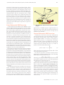
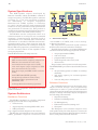
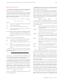
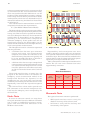
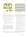
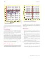
20
Achieving 20cm Positioning Accuracy in Real Time
Using GPS – the Global Positioning System
by E. MASELLA, B.Eng., P.E.
Marconi Canada
Marconi Canada (part of the Marconi North
America Group of Marconi Electronic Systems) is a
recognized world leader in the design, manufacĆ
ture, sale and support of highĆtechnology elecĆ
tronic products for the aerospace and
communications market, for both military and
commercial applications. Its headquarters and
principal design and manufacturing facility is
located in StĆLaurent, Quebec (in the greater
Montreal area). Its facilities include a branch plant
in Kanata, Ontario (in the Ottawa area), as well as
sales and service offices across Canada. A photoĆ
graph of the Company's headquarters is
presented in fig. 1.
Marconi Canada is a pioneer in the design and
manufacture of GPS receivers. The first receiver
development took place in the early 1980s with a
military receiver development for the Canadian
Department of National Defence. Then, in the
midĆ1980s, the first commercial GPS receiver was
developed. The next major development took
place in the early 1990s for a GPS receiver to be
installed on the new Boeing 777 aircraft. This
marked the beginning of a series of successes for
Marconi Canada in the commercial avionics
market, and the Company is now recognized as a
world leader in this area.
In the midĆ1990s, a new group was created with
the objective of porting our GPS technology on
lowĆcost hardware platforms. This initiative has
been a success as well, with the development of a
variety of products targeted towards the consumer
1
The headquarters of Marconi Canada
Erik Masella gained his bachelor's degree in
Electrical Engineering at the University of
Sherbrooke in 1991. In 1992 he joined the
Aerospace Group of Marconi Canada and has
been involved in the design and test of airborne
GPS software and GPSĆaided landing systems.
In 1996 he joined the GPS OEM Group. Since
then he has been involved in the development
of new GPS products for the consumer market.
He is a chartered Professional Engineer.
(EĆmail: [email protected])
Glossary
ASIC
Application Specific Integrated Circuit
DGPS
Differential Global Positioning System
FEPROM Flash Erasable Programmable
ReadĆOnly Memory
IF
Intermediate Frequency
I/O
Input/Output
OEM
Original Equipment Manufacturer
PVT
Position, Velocity and Time
RF
Radio Frequency
RISC
Reduced Instruction Set Computer
RTK
RealĆTime Kinematic
UART
Universal Asynchronous
Receiver/Transmitter
market, namely: automatic vehicle location
systems, marine navigation, golf yardage systems,
surveying systems, and also some military
applications requiring commercial offĆtheĆshelf
(COTS) solutions.
Introduction to GPS
The NAVSTAR (NAVigation Satellite Timing And
Ranging) Global Positioning System, better known
as GPS, is a radionavigation system using a
network of satellites distributed over six orbital
planes. GPS provides accurate 3ĆD position, velĆ
ocity and time information, and worldĆwide
24Ćhour coverage to an unlimited number of users
with allĆweather operation. GPS is a oneĆway
ranging system: signals are transmitted only by
the satellites. Each GPS satellite transmits signals
centred on two microwave frequencies:
1575.42ĂMHz, referred to as Link 1, or simply L1; and
1227.60ĂMHz, referred to as L2.
The L1 signal is modulated with (i) the Coarse
Acquisition (or C/A) Code, a coarse ranging
signal; (ii) the Precise (P) Code, a precise, but
encrypted, ranging signal; and (iii) navigation
data at 50 bits per second. L2 is modulated only
GEC REVIEW, VOL. 14, NO. 1, 1999
ACHIEVING 20CM POSITIONING ACCURACY IN REAL TIME USING GPS
21
with the PCode and the navigation data. Auth
orized users only (U.S. Department of Defense and
allies) have access to the decryption keys of the
PCode, which by its nature has much higher anti
jamming properties than the C/ACode. Using the
ranging signal and the navigation data, a GPS
receiver can measure the range between the
satellite and the receiving antenna, and compute
the exact position of the transmitting satellite.
Hence, with three satellites, the 3D position of the
receiver may be computed, and a fourth is
required for solution of the time. An excellent
overview of the GPS system operation is given in
reference (1).
Code Differential GPS Overview
Code Differential GPS (Code DGPS) is the
regular Global Positioning System with the addi
tion of a differential signal that conveys correction
data. These data significantly increase the accu
racy of the GPS navigation function and can be
broadcast over any authorized communication
channel. In these systems, a GPS receiver is
located at a known (surveyed) position: this
receiver is usually referred to as a reference sta
tion. The reference station makes measurements
on the satellite's signal and estimates the measure
ment errors using its surveyed geodetic position.
The errors include the signal transmission delays
caused by the ionosphere and the troposphere, as
well as Selective Availability (S/A) - an intentional
signal degradation introduced by the U.S. Depart
ment of Defense, in an effort to restrict the accuracy
capability of most civilian GPS users.
In layman's terms, because the reference station
knows precisely where it is and computes a differ
ent position using the GPS signals, it can estimate
the errors in its signal measurements. These errors,
or differential corrections (that is, the difference
between the true range and the measured range),
are then transmitted to roving receivers by radio or
other means. They can then be applied to GPS
measurements from the roving GPS receiver, and
used to remove the systematic (correctable) error
factors, because most of these errors will be similar
for the roving receivers. Note that the correlation
factor between errors observed at both sites
largely depends on the distance between the two
receivers.
A DGPS system therefore consists of at least two
units: a reference station and one (or several)
roving units. The reference station broadcasts its
differential data and the roving units receive it
through a data port, directly connected to a radio
receiver. The roving units can then display
position, velocity, time (PVT) and other information,
as needed for their marine, land or aeronautical
2
Code Differential Global Positioning System (DGPS)
example
applications. A DGPS system implementation is
depicted in fig. 2 (note that the reference station is
located on the ground and the roving unit is
located in the aircraft).
Carrier Differential GPS Overview
A different, and more accurate, differential
correction technique involves tracking of the satel
lite signal's carrier phase, and is called carrier
phase DGPS. When a receiver navigates in
carrierphase mode, it is measuring a different
GPS observable, namely the GPS carrier wave. To
do so, it must measure the phase of the carrier
continuously from signal lock time, t0, in order to
produce the following observable:
t
f m(t) + f(t + t 0) )
ŕ fdt,
(1)
t0
where f is the received carrier phase and f is the
received Doppler frequency.
In order to produce a range measurement
between the satellite and the user, the following
observable must then be formed:
(2)
ò f(t) + N 0 ) f m(t),
where N0 is an exact number of cycles between the
user and the satellite at time t0. fm thus represents
the change in cycles since time t0.
However, the initial number of wavelengths N0
between the satellite and the receiver is unknown.
This is called the carrier phase ambiguity and
must be estimated. In order to estimate this ambi
guity, it is necessary for the roving GPS unit to use
information (that is, carrierphase measurements)
from a reference station. This technique yields
accuracies in the cmrange in dynamic environ
ments and is called 'Realtime Kinematic', or RTK,
GPS. A rather good (albeit brief) introduction to
code and carrierphase DGPS is presented in
reference (2).
GEC REVIEW, VOL. 14, NO. 1, 1999
22
E. MASELLA
System Specifications
The RTKcapable engine developed by
Marconi Canada, called the RT•Star, consists of
singlefrequency (L1) RTK Navigation software
residing on a lowcost hardware platform
for embedding in Original Equipment
Manufacturer (OEM) systems. It measures
4 2.65 (100mm 67mm) and consumes 2W.
Details of its use, performance and specifications
are presented in reference (3). This product is
considered to possess one of the highest accuracy
overprice ratios in the OEM sensor industry.
The RT•Star can be configured either as a
reference station or a roving unit via a command
message. Communication between both is
implemented via a standard radio link and the
information is encoded in RTCM104 format(4).
Communication from a host computer with the
GPS engine is performed via a serial port using an
RS232 Marconiproprietary transmission proto
col. The reference station is also capable of self
surveying its position.
The RT•Star has the following features:
S
S
S
S
S
S
S
S
S
12 parallel tracking channels;
GPS measurements sampling aligned on
GPS time onesecond rollover event;
raw measurement output rate of 10Hz;
time mark signal output aligned on GPS
time onesecond rollover event;
keepalive input pin (RAM and/or realtime
clock);
dual UART (third UART optional);
six input/output discrete control lines;
reprogrammable operational code
(FEPROM); and
rechargeable lithium battery (optional).
The RT•Star is compatible with both active and
passive antennas.
System Architecture
Hardware Overview
The RT•Star hardware is a highly integrated
design built around three components(5):
S RF frontend,
S digital signal processing (DSP) ASIC, and
S RISC processor.
Fig. 3 depicts a block diagram of the receiver.
The RF chip, preceded by a lownoise amplifier
(LNA), performs a triple IF conversion, from
Receiver block diagram
3
1575.42MHz to 4.3MHz, and a 2bit analog
todigital conversion.
The temperaturecontrolled crystal oscillator
(TCXO) is the receiver's reference oscillator.
The DSP chip includes a 12channel GPS signal
correlator and the following peripheral circuits:
S
two programmable UARTs;
S
realtime clock;
S
S
programmable interrupts;
watchdog and reset circuit; and
S
discrete I/Os.
The processor is the system's critical component.
The ARM60 RISC processor was selected because
it has:
S
S
S
the processing power to handle 12 tracking
channels;
30% spare capacity for customerspecific
tasks; and
low cost and power consumption.
Software Overview
The embedded software was developed using
objectoriented design and programming
techniques in order to yield reusable software
components and to encapsulate the functions most
subject to change. The major objects encapsulate
the following functionalities:
S
Signal Processing;
S
S
Satellite List Management;
I/O Management;
S
Differential Data Processing; and
S
Navigator.
The Navigator is the ultimate recipient of the
work produced by the other objects: it receives all
the data (measurements, differential data, satellite
data...) and produces a PVT estimate.
GEC REVIEW, VOL. 14, NO. 1, 1999
ACHIEVING 20CM POSITIONING ACCURACY IN REAL TIME USING GPS
Navigator Overview
A comprehensive description of the Navigator's
algorithms is presented in reference (6). Only a
brief overview is presented below.
One of the first steps to be performed in an RTK
Navigation solution is to form two sets of observ
ables: the single and the doubledifferences(2).
Both are derived using the carrier phase observ
able, which is defined as:
ò f + R ) c(Dt u * Dt s * Diono ) Dtropo)
) å orbit)N 0l)h f ,
(3)
where:
R
is the true range between satellite and user;
c
Dt
is the speed of light;
u
Dt s
is the satellite's clock offset, including
relativistic effects;
Dtropo is the total tropospheric delay;
is the error introduced by the orbital data;
is the initial carrier phase ambiguity;
l
is the signal's wavelength (19cm for L1);
and
is the error caused by the receiver thermal
hf
noise; it is a Gaussian process with zero
mean.
Note that in eqn. (3), R is the true range between
the satellite and the user. Geometrically, this can
be expressed as:
R + Ǹ(x s * x u) 2)(y s * y u) 2)(z s * z u) 2 ,
(4)
s
s
s
where x , y , z are the satellite's coordinates as
provided by the satellite's navigation data and x u,
y u, z u are the unknown user's coordinates.
A singledifference across satellites is defined as
the instantaneous difference in the carrier phase
measurement made by the same receiver observ
ing two satellite signals simultaneously. The
singledifference operator is denoted as ʼn. From n
satellites (n-1) singledifferences can be formed.
The simplest way of forming these (n-1) observ
ables is by selecting a reference satellite, s*, and
applying the operator ʼn as follows:
ʼnf si,s* + f usi * f us*,
(5)
where f represents the phase measurement by
the user of satellite i.
u
si
Expanding eqn. (5) using eqn. (3) shows that the
receiver clock errors are removed in the resulting
singledifference observable.
To form the next observable, a doublediffer
ence, a set of (n-1) singledifferences must be
formed with measurements from the roving user.
Hence a set of (n-1) singledifferences are formed
with measurements received by the reference
station on the differential link. A doubledifference
would read as follows:
(6)
Dʼnf r,siu,s* + ʼnf rsi,s* * ʼnf usi,s*.
The property of this observable is that satellite
clock errors are removed. Expansion of eqn. (6)
with eqns. (3) and (5) yields an equation in which
the unknowns are:
DʼnR,
is the user's clock offset from true time;
Diono is the total ionospheric advance (the
dispersive property of the ionosphere on
the carrier actually causes an advance of
the signal with respect to the modulated
code);
å orbit
N0
23
the value of the geometric distance of
the doubledifference across satellites
and receivers;
Dʼniono , the value of the double advance of the
carrier because of the ionosphere
across satellites and receivers;
Dʼntropo , the value of the doubledifferenced
delay of the carrier because of the
troposphere across satellites and
receivers;
DʼnN 0 ,
the doubledifferenced ambiguity
expressed in cycles (it is itself an integer
since it is the algebraic sum of four
integers);
Dʼnå orbit ,
Dʼnh f ,
the value of the doubledifferenced
orbital errors across satellites; and
the doubledifferenced phase noise
(the sum of four Gaussian processes
with zero mean).
Because Dʼnh f may be neglected if the receiver
has relatively low phase noise, as well as Dʼnå orbit
(beyond the scope of this text), and because
Dʼniono and Dʼntropo may be modelled, only
DʼnN 0 remains to be properly estimated in order to
solve for R. Fortunately, N0 is a constant, hence it
may be estimated over time using the carrier
phase observables.
So, as we can see, a set of synchronized carrier
phase measurements (that is, measurements that
are sampled at the same time) from the reference
station and the roving unit is required at the latter.
One problem which arises is that the data link that
provides the carrier measurements from the refer
ence station has a given transmission latency.
Consequently, the roving unit will receive its
reference measurements with a typical latency of
1 to 2 seconds. Because a Navigation solution is
required for the current time, the roving unit will
have to have some means of extrapolating the
GEC REVIEW, VOL. 14, NO. 1, 1999
24
E. MASELLA
reference measurements for the current time (that
is, coincident with the unit's measurement time);
then timematched doubledifferences can be
produced. This extrapolation process is implem
ented using PositionVelocityAcceleration (PVA)
tracking filters, which are not discussed here, but
interested readers may find details on these filters
in reference (7).
One realizes that the estimated state vector X is
composed of two basic sets of parameters:
X = {User Model | Measurement Model}
The observability on these two sets is quite differ
ent. The user model represents the dynamics of the
roving user. This set must be updated at the basic
rate of the Navigator. However, the measurement
model builds its observability on the change of
geometry of the satellites that compose the
unknown ambiguity. A fast update rate will not
significantly improve the observability on the
measurement model because of the high accuracy
of the carrier phase measurements.
The Navigation function is therefore separated
into two processes:
S
a Kalman filter that acts upon reference
station and roving unit measurements
sampled at the same time. Because of the
data link latency, this solution is typically old
by a few seconds. This filter is referred to
herein as the `OffLine Filter'; and
S
a Kalman filter that acts upon extrapolated
reference station measurements and roving
unit measurements sampled for the current
time. The update rate of this filter is currently
at 1Hz. It is referred to herein as the `OnLine
Filter'.
These findings therefore suggest that the
purpose of the OffLine Filter is to estimate the
ambiguity vector (measurement model) in the
background. Because the dynamics of the
ambiguities are very small (they tend towards
constants), this filtering can be executed at a rate
significantly lower than the required navigation
rate.
The OnLine Filter is thus used to provide user
PVT estimates at the nominal navigation rate.
It will use the ambiguity vector computed by the
OffLine Filter.
Sample reset test
4
Repeatability and convergence time were
tested by forcing a system reset every 20 minutes
over a period of 24 hours. A sample of one reset test
is shown in fig. 4. The reset times are marked with a
cross on the time axis. It is observed that the system
repeatedly converges towards zero error.
Table 1 shows some statistics generated from the
results. The 3D r.m.s. error reaches 20cm after
approximately 7 minutes.
TABLE 1
Reset Tests Statistics
Time after
reset
(minutes)
North
r.m.s. error
(cm)
East
r.m.s. error
(cm)
Vertical
r.m.s. error
(cm)
5
23
8
12
10
8
6
8
20
7
3
6
Kinematic Tests
Static Tests
Two types of kinematic tests were performed:
A series of tests was carried out using three
surveyed antennas located on Marconi Canada's
roof, in order to establish the accuracy, conver
gence time and functional behaviour of the
RT•Star in static mode.
S
GPS signal simulator tests to verify the
absolute accuracy of the solution; and
S
field tests to verify reallife accuracy and
functionality of the system.
GEC REVIEW, VOL. 14, NO. 1, 1999
ACHIEVING 20CM POSITIONING ACCURACY IN REAL TIME USING GPS
Simulator test set-up
5
GPS Signal Simulator Tests
The purpose of the simulator test was to verify
the accuracy of the RT•Star in a normal dynamic
environment. Two Nortel model STR2760 GPS sig
nal simulators were set up in differential mode to
carry out this test. Fig. 5 depicts the test
setup.
The test simulates an aircraft performing
dynamic manuvres. The scenario is as follows:
25
Simulator test position errors
6
tests were performed using a reference station
located on the Company's roof and a vehicle
equipped with an antenna and an RT•Star. The
vehicle followed a route located in an urban zone
with a surveyed geodetic marker situated on the
route. The test procedure is as follows:
S
the antenna is fixed to a surveying rod set on
top of a geodetic marker located in front of
the Company building;
S
system is poweredon and remains static for
2 minutes;
S
the aircraft is static for 10 minutes;
S
it accelerates linearly with a 1g acceleration
up to 100m/s;
S
it climbs to an altitude of 1km;
S
S
it then completes a square path at a constant
speed of 100m/s with 10 minutes between
each turn;
the antenna is relocated on the vehicle's roof
(the operator triggers a signal that logs the
time at which the antenna is removed);
S
S
it touches ground and decelerates to 0m/s;
and
the vehicle drives around the Company site
and stops at the geodetic marker;
S
it remains static for 5 minutes.
S
the antenna is removed from the rooftop and
set on top of the marker (the operator triggers
a signal that logs the time at which the
antenna is set);
S
the antenna remains static for
approximately 2 minutes, the operator
triggers the removal time log and relocates
the antenna on the vehicle.
The position solution generated in real time by
the RT•Star was logged and then compared to the
truth file of the simulator, which is a file containing
the true vehicle position at each GPS second. The
results were processed with the MATLABt data
analysis tool (provided by the MathWorks Inc.) and
the NorthEastDown position errors are presented
in fig. 6.
Field Tests
The purpose of these tests was to verify the
accuracy and the functionality of the RT•Star in a
reallife environment. Several kinematic baseline
The above routine was repeated ten times.
Fig. 7 shows the position in the vertical plane.
The red marks on the time axis represent the
periods at which the antenna was located on the
survey point. It is observed that repeatable results
are obtained at each run.
GEC REVIEW, VOL. 14, NO. 1, 1999
26
E. MASELLA
8
Horizontal position error on survey point
7 Vehicle vertical difference
The error in the horizontal plane of the computed
position of the marker at each run is presented in
fig. 8.
Conclusions
The tests conducted on the RT•Star show that
20cm positioning accuracy can be obtained in
real time using GPS. Furthermore, the results have
been proven to be repeatable.
The RT•Star (fig. 9) is considered an excellent
tradeoff between lowcost code differential GPS
systems delivering 1metre accuracy levels and
highend twofrequency RTK systems offering an
accuracy level of only a few centimetres. It is suited
for a variety of applications, namely precision
agriculture, aircraft positioning and machine
control. It also gives the user the flexibility to confi
gure the receiver either as a reference station or a
roving unit via a command message.
the IEEE Position Location and Navigation
Symposium `98 in April 1998 at Palm Springs, CA,
USA, and published in the conference
proceedings.
References
1
MILLIKEN, R.J. and ZOLLER, C.J., `Principle of operation of
NAVSTAR and system characteristics', Global Positioning
System, Journal of the Institute of Navigation, 1, pp. 314,
1980.
2
LANGLEY, R.B., `RTK GPS', GPS World, pp. 7076, September
1998.
3
RT•Star User's Manual, ver. 001, Canadian Marconi
Company publication no. 1220GEN0101, February 1998.
4
RTCM Recommended Standards for Differential NAVSTAR
GPS Service, ver. 2.1, RTCM Special Committee104,
January 1994
5
T HÉROUX , Y., `Open architecture design for GPS
applications', Proceedings of the ION GPS95, The 8th
International Technical Meeting of The Satellite Division of
the Institute of Navigation, pp. 117121, 1995.
6
MASELLA, E., GONTHIER, M. and DUMAINE, M., `The RT•Star:
features and performance of a lowcost RTK OEM sensor',
Proceedings of the ION GPS97, The 10th International
Technical Meeting of The Satellite Division of the Institute of
Navigation, pp. 5359, 1997.
7
R AMACHANDRA , K.V., M OHAN , B.R. and G EETHA , B.R.,
'A threestate Kalman tracker using position and rate
measurements', IEEE Transactions on Aerospace and
Electronic Systems, 29, 1, pp. 215221, January 1993.
Acknowledgement
This paper is based on a presentation, entitled
`Precise Kinematic Positioning Experiments with a
LowCost RTK GPS Engine', given by the author at
GEC REVIEW, VOL. 14, NO. 1, 1999
ACHIEVING 20CM POSITIONING ACCURACY IN REAL TIME USING GPS
9
27
The RTSStar smart antenna unit: an RTSStar (shown inset) embedded in a GPS antenna
GEC REVIEW, VOL. 14, NO. 1, 1999