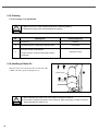
1
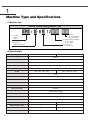
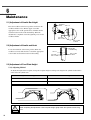
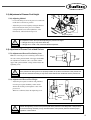
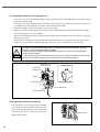
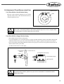
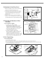
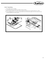
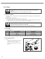
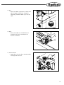
R
User’s
Manual
SPS/D-BR1254H
Electronically Controlled
Direct Drive Type Pattern
Tacking Sewing Machine
(Machine Structure Part)
SUNSTAR MACHINERY CO., LTD.
1) FOR AT MOST USE WITH EASINESS,
PLEASE CERTAINLY READ THIS MANUAL
BEFORE STARTING USE.
2) KEEP THIS MANUAL IN SAFE PLACE
FOR REFERENCE WHEN THE MACHINE
BREAKS DOWN.
MME-060214
lity
a
u
tQ
Besst Pricevice
Be st Ser
Be
1. Thank you for purchasing our product. Based on the rich expertise and
experience accumulated in industrial sewing machine production, SUNSTAR
will manufacture industrial sewing machines, which deliver more diverse
functions, high performance, powerful operation, enhanced durability, and
more sophisticated design to meet a number of user’s needs.
2. Please read this user’s manual thoroughly before using the machine. Make
sure to properly use the machine to enjoy its full performance.
3. The specifications of the machine are subject to change, aimed to enhance
product performance, without prior notice.
4. This product is designed, manufactured, and sold as an industrial sewing
machine. It should not be used for other than industrial purpose.
R
SUNSTAR MACHINERY CO., LTD.
Contents
1. Machine Type and Specifications .............................................................................. 6
1.1) Machine Type .................................................................................................................... 6
1.2) Specifications .................................................................................................................... 6
2. Safety Rules ......................................................................................................................... 7
2.1) Safety Marks ..................................................................................................................... 7
2.2) Machine Delivery .............................................................................................................. 8
2.3) Machine Installation .......................................................................................................... 9
2.4) Machine Operation ............................................................................................................ 9
2.5) Repair and Maintenance ................................................................................................. 10
2.6) Type of Safety Labels ..................................................................................................... 10
2.7) Location of Safety Labels ............................................................................................... 11
3. Assembly ............................................................................................................................ 12
3.1) Name of Machine Parts .................................................................................................. 12
3.1.1) Name of Machine Parts ....................................................................................... 12
3.2) Machine Installation ........................................................................................................ 13
3.2.1) Installation Environment ..................................................................................... 13
3.2.2) Electricity Environment ....................................................................................... 13
3.2.3) Table Installation .................................................................................................. 13
3.3) Machine Assembly ......................................................................................................... 14
3.3.1) Table Assembly ................................................................................................... 14
3.4) Accessory Installation ..................................................................................................... 16
3.4.1) Installation of Motor Cover ................................................................................. 16
3.4.2) Installation of Safety Plate ................................................................................... 16
3.4.3) Installation of Thread Stand ................................................................................ 16
3.5) Installation of Pneumatic Parts ....................................................................................... 17
3.5.1) Filter Regulator .................................................................................................... 17
3.5.2) Pneumatic Hose Connection ............................................................................... 18
4. Machine Operation ......................................................................................................... 20
4.1) Oil Supply ....................................................................................................................... 20
4.1.1) Supplying Location .............................................................................................. 20
4.2) Needle .............................................................................................................................. 20
4.2.1) Needle Installation ............................................................................................... 20
4.3) Thread .............................................................................................................................. 21
4.3.1) Upper and Lower Thread Placement .................................................................. 21
4.3.2) Threading ............................................................................................................. 21
4.3.3) Bobbin Case Insertion/Removal ......................................................................... 21
4.3.4) Tension Adjustment ............................................................................................. 22
4.3.5) Lower Thread Winding ....................................................................................... 23
4.3.6) Adjustment of Thread Winder Wheel Location ................................................. 23
4.4) Pedal Operation ............................................................................................................... 23
4.4.1)
-20 Model .................................................................................................... 23
4.4.2)
-22 Model .................................................................................................... 24
4.6) Pressured Air Infusion and Adjustment of Air Pressure ............................................... 24
4
4.6.1) Pipe Connection for Pressured Air ...................................................................... 24
4.6.2) Adjustment of Air Pressure ................................................................................. 24
4.7) Adjustment of Driving Belt Tension .............................................................................. 25
4.8) Upper Thread Holding Device (Optional) ..................................................................... 25
4.8.1) Adjustment of Upper Thread Holding Device ................................................... 25
5. Maintenance ...................................................................................................................... 26
5.1) Adjustment of Needle Bar Height .................................................................................. 26
5.2) Adjustment of Needle and Hook .................................................................................... 26
5.3) Adjustment of Feed Plate Height ................................................................................... 26
5.3.1) Adjusting Method ................................................................................................ 26
5.4) Adjustment of Presser Foot Height ................................................................................ 27
5.4.1) Adjusting Method ................................................................................................ 27
5.5) Adjustment of Presser Foot-related Devices .................................................................. 27
5.5.1) Adjustment of Presser Foot Driving Cam .......................................................... 27
5.5.2) Adjustment of Presser Plate Height .................................................................... 27
5.5.3) Adjustment of Presser Foot Adjusting Arm ....................................................... 28
5.5.4) Adjustment of Presser Foot Stroke ..................................................................... 28
5.6) Adjustment of Thread Release-related Parts .................................................................. 29
5.6.1) Thread Release Notch Position Setting .............................................................. 29
5.6.2) Thread Release Stopper Position Setting ............................................................ 29
5.6.3) Adjustment of Thread Guide Disk Opening ....................................................... 30
5.7) Adjustment of Trimming-related Parts ........................................................................... 31
5.7.1) Trimmer Cam Position Setting ............................................................................ 31
5.7.2) Adjustment of Link Stopper Screw ..................................................................... 31
5.7.3) Trimmer Shaft Position Setting ........................................................................... 32
5.7.4) Link Stopper Position Setting ............................................................................. 32
5.7.5) Adjustment of Moving and Fixed Blades ........................................................... 32
5.8) Adjustment of Bobbin Thread Volume .......................................................................... 33
5.9) Adjustment of Hand Pulley Device ................................................................................ 34
5.10) Assembly and Adjustment of Direct Drive Motor ...................................................... 34
5.10.1) Assembly of Coupling ....................................................................................... 34
5.11) X, Y Origin Setting ....................................................................................................... 34
5.11.1) X Origin Setting ................................................................................................. 34
5.11.2) Y Origin Setting ................................................................................................. 35
5.12) Oil Supply ..................................................................................................................... 36
5.12.1) Regular Check List ............................................................................................ 36
5.12.2) Oil Supply .......................................................................................................... 36
5.12.3) Oil Supplying Method ....................................................................................... 36
5.13) Cleaning ......................................................................................................................... 38
5.13.1) Cleaning Cycle and Method .............................................................................. 38
5.14) Handling of Waste Oil .................................................................................................. 38
6. Troubleshooting .............................................................................................................. 39
6.1) Machine Part ................................................................................................................... 39
5
1
Machine Type and Specifications
1.1) Machine Type
Pattern Tacking Sewing Machine Type
SPS / D- BR 12
③ Purpose
H : Heavy materials
HC : Heat Cutter
① SunStar
Pattern
System
④ Pattern Tacking S/M Name
54 : 50×40mm
63 : 60×30mm
② Series Type
D: Motor Direct Drive
⑤ Hook Type
R : Rotary hook
1.2) Specifications
Type
SPS/D-BR1254HC
Sewing Speed
2500spm
Sewing Scope (X, Y)
50mm×40mm
Stitch Length
0.1~10mm
Feed Plate Lift
20mm
Presser Foot Lift
41.2mm
Needle
DP17×#21, DP17×#23
DP17×#25, DP17×#26
Take Up Lever Stroke
72mm
Hook
Full Rotary 3-fold Capacity Hook
No. of Stitch Input
10,000 Stitches
No. of Basic Pattern Input
56 Patterns
Memory
EP RCM
Zoom-in/out Scope
20~200%
Motor
AC Servo Motor 500W
Power consumption
600VA
Height of Presser Foot
Air Cylingder Type
Wiper
Air Cylingder Type
Presser Foot
○
○
Secpmd Thread Tension
×
○
Heat Cutter
×
○
Power
6
SPS/D-BR1254H
Free Voltage (110V/220V)
2
Safety Rules
2.1) Safety Marks
The safety marks in this user’s manual are divided into Caution , Danger , and Warning . They indicate that if the
safety rules are not kept, injury or damage to machine might occur as a result.
No.
Name
Description
Caution
If the machine is not properly handled, it may cause injury to
users or physical damage to the machine.
Warning
If the machine is not properly handled, it may cause death or
severe injury to users.
Danger
If the machine is not properly handled, it may cause death or
severe injury to users, and the urgency of the danger is very
high.
Caution
Warning
Danger
7
2.2) Machine Delivery
Mark
Description
The machine delivery shall be conducted by the persons who are knowledgeable about
the safety instructions and rules. The following safety rules must be observed:
2.2.1) Manual delivery
When the machine is delivered by persons, they shall wear special shoes and tightly hold the
machine on the left and right sides.
Danger
2.2.2) Forklift delivery
1) A forklift shall be big enough to endure the weight of the sewing machine and carry the
machine.
2) Use the palette when lifting the machine. Set the gravity center of the machine (center of
the left and right sides) at the fork arm of the forklift and carefully lift the machine.
Ban people from
standing under the
machine and remove
obstacles near the
machine.
Warning
8
Make sure to maintain the balance of the machine when unloading the
machine by using a forklift or crane to prevent the deformation of the
machine or to prevent people from being exposed to danger.
2.3) Machine Installation
Depending on the installation environment, function errors, breakdown, or other physical
damage might result. Make sure to meet the following conditions for machine installation:
Caution
1) The workbench or table where the machine is installed should be durable enough to endure
the weight of the machine (see the name plate).
2) Dust and humidity are the cause of machine pollution and erosion. Please install an air
conditioner and conduct regular maintenance of the machine.
3) Install the machine at the place where it is not exposed to direct sunlight (if the machine is
exposed to direct sunlight for a long time, it may cause discoloration or deformation).
4) Secure the space around the machine. Place the machine at least 50cm away from the left,
right, and rear walls to secure sufficient space for maintenance activities.
5) Explosion risk: To prevent possible explosion, immediately stop the machine operation if
there are inflammable materials in the air.
6) Lighting: The machine does not offer lighting devices. When necessary, install needed
lighting.
7) Overturn risk: Do not install the machine on the unstable stand or table. If the machine drops,
it may cause injury or severe impact on the machine. If the machine is suddenly stopped or
the external impact is imposed, the machine might be capsized.
2.4) Machine Operation
The machine body is attached with Caution and Warning stickers at each dangerous
part to emphasize safety instructions. With the full understanding of the safety
instructions, make sure to observe the following during machine operation:
Warning
1) Before turning on the power, read this manual thoroughly and have a full understanding of
machine operation.
2) Get properly dressed. Long hair, necklace, bracelet, or wide sleeve might be fed into the
machine during operation. Wear slip-free shoes to prevent slipping on the floor.
3) Check the moving scope of machine before its operation to find out whether the scope is
proper.
4) Keep hands and head away from the machine parts where accidents might occur (needle,
hook, thread take-up lever, pulley, etc.) during operation.
5) Do not remove the safety cover which protects pulley and shaft during machine operation
for user’s safety.
6) Cut the power supply before disassembling the electric box such as the control box, and
double-check that the power switch is“Off.”
7) Make sure that the power switch is“Off”when the upper shaft is manually rotated.
8) Stop the machine when the needle is replaced or when inspecting the machine after sewing
work is done.
9) Make sure to follow the cautions below. Otherwise, physical damage to the machine such as
malfunction and breakdown might result:
- Do not put articles on the S/M table.
- Avoid using a crooked needle or the needle with damaged tip.
- Use the feed plate appropriate to working conditions.
9
2.5) Repair and Maintenance
When machine repair is needed, it shall be conducted by SunStar A/S engineers only
who have finished the due training course.
1) For cleaning and repair, cut off the main power supply. Wait for 4 minutes before starting
maintenance to make the machine completely discharged.
For main shaft motor and X,Y drive box, it takes 10 minutes before they
are completely discharged after the main power is cut off.
Danger
Caution
2) Do not modify the machine specifications or parts without substantial consultations with
SunStar. Otherwise, it may threaten safety during machine operation.
3) Use the parts manufactured by SunStar to repair or replace the machine parts during A/S
service.
4) When repairing is completed, re-install all the removed safety covers.
2.6) Type of Safety Labels
CAUTION
경 고
Do not operate without finger guard and
safety devices. Before threading, changing
bobbin and needle, cleaning etc. switch
off main switch.
손가락 보호대와 안전장치 없이 작동하지
마십시오.
실, 보빈, 바늘교환시나 청소전에는 반드시
주전원의 스위치를 꺼 주십시오.
Do not operate without finger guard and safety devices. Before
threading, changing bobbin and needle, and cleaning, turn off the
main switch.
WARNING
경 고
Hazardous voltage will cause injury.
Be sure to wait at least 360 seconds
before opening this cover after turn off
main switch and unplug a power cord.
고압 전류에 의해 감전될 수 있으므로 커버를
열 때는 전원을 내리고 전원 플러그를 뽑고 나
서 360초간 기다린 후 여십시오.
10
Hazardous voltage will cause injury.
Be sure to wait at least 360 seconds before opening this cover after
turn off main switch and unplug a power cord.
2.7) Location of Safety Labels
CAUTION
경 고
Do not operate without finger guard and
safety devices. Before threading, changing
bobbin and needle, cleaning etc. switch off
main switch.
손가락 보호대와 안전장치 없이 작동하지
마십시오.
실, 보빈, 바늘교환시나 청소전에는 반드시
주전원의 스위치를 꺼 주십시오.
WARNING
경 고
Hazardous voltage will cause injury.
Be sure to wait at least 360 seconds
before opening this cover after turn off
main switch and unplug a power cord.
고압 전류에 의해 감전될 수 있으므로 커버를
열 때는 전원을 내리고 전원 플러그를 뽑고 나
서 360초간 기다린 후 여십시오.
11
3
Assembly
3.1) Name of Machine Parts
3.1.1) Name of Machine Parts
Motor Care
Arm
Thread Stand
Emergency
Stop Switch
Safety Plate
OP Box
Power Switch
Control Box
Pedal
12
3.2) Machine Installation
3.2.1) Installation Environment
1) To prevent accidents stemming from mal-operation, do not use the machine if the voltage is 10% above the rated
voltage.
2) To prevent accidents stemming from mal-operation, make sure to check if the air pressure is proper before using any
air pressure devices such as air cylinder.
To guarantee smooth operation of the product, the installation environment shall be prepared as
described in User’s Manual. Otherwise, unexpected damage might occur to the product.
Caution
3) Proper temperature during machine operation : 0°~ 40°C (32°~ 104°F)
4) Proper temperature during machine storage : -25°~ 55°C (-13°~ 131°F)
5) Humidity : Relative humidity – within 45 ~ 85%
3.2.2) Electricity Environment
The voltage shall be within 10% of the rated voltage.
Warning
1) Power voltage
- The power voltage shall be within 10% of the rated voltage.
- It is recommended to use the power frequency within +/- 1% of the rated frequency (50/60Hz).
2) Noise of electromagnetic wave
- Do not share the power with the products which have either strong magnetic field or use high frequency. Make the
machine stay away from the products mentioned above.
3) Take care not to spill water and coffee on the machine.
4) Do not drop Control Box and the motor to the floor.
3.2.3) Table Installation
1) Table fixing
- Insert the shock absorbing rubber into the level adjuster and raise it until the caster freely moves.
- After the table is installed, tighten the nut to fix the level adjuster.
2) Table height adjustment
- Use the bolts attached to the table to adjust the height of the table to make sure that the users can smoothly and
conveniently work.
Bolt
Nut
Level Adjuster
Shock Absorbing
Rubber
Caster
13
To prevent safety accidents, at least two persons shall be assigned to machine installation or
machine delivery.
Caution
3.3) Machine Assembly
3.3.1) Table Assembly
1) Install the waste oil can support, the oil dish, the
control box, and the power switch on the table.
Oil Dish
Waste Oil
Can Support
Control Box
Power Switch
2) Install the bed cushion rubber and the support rubber
for safety switch to prevent the machine vibration
and noises from occurring.
Safety Switch
Supporting Rubber
Bed Cushion
Rubber
3) To fix the machine, attach the hinge and the hinge
rubber to the bed, and install them on the table by
using fixing bolts.
Fixing Bolt
Hinge
Rubber
Hinge
14
4) Since the machine has not been fully assembled, take
caution to lean the assembled machine toward the
floor, and insert and fasten the bolt into the hinge to
completely fix the machine to the table.
Fixing Bolt
To prevent safety accidents, at least two persons shall be assigned to machine installation or
machine delivery.
Caution
5) Install the safety switch and safety switch bracket on
the sewing machine, and then adjust the bracket
location of the safety switch to make sure that the
attached safety switch can properly operate.
Safety Switch
Bracket
Safety Switch
Supporting Rubber
Tightening Screw
Safety Switch
6) Complete the cable connection between the machine
and the control box, and fix the cables under the table
as in the figure (Determine the length of the cables
when fixing in consideration of the machine’s
erection).
Table
15
3.4) Accessory Installation
3.4.1) Installation of Motor Cover
Fixing Screw
Attach the motor cover to the rear side of the machine by
using four fixing screws (4EA, small size).
Motor Cover
3.4.2) Installation of Safety Plate
Face Plate
Attach the safety plate to the head.
Safety Plate
To guarantee safety, make sure to install the safety plate before using the machine.
Caution
3.4.3) Installation of Thread Stand
Assemble the thread stand and install it on the table.
Make adjustment to properly locate the thread stand.
16
3.5) Installation of Pneumatic Parts
3.5.1) Filter Regulator
Install the filter regulator on the right side of the table
leg.
Caution
1) Adjust the pneumatic pressure to 5~5.5kgf/cm (0.49~0.54MPa).
2) If the pneumatic pressure goes below 4kdf/cm, the error message appears, and at the same
time the machine stops its operation [ Error message : Err 24 (Low Pressure!) ].
3) When the finger valve is closed after use, the remaining air is automatically released, and the
remaining pressure is displayed at 0Mpa (0kgf.cm).
17
3.5.2) Pneumatic Hose Connection
1) Pneumatic hose connection for all-in-one type feed frame (SPS/D-BR1254A-20 / BR1263A-20)
②
①
1. Connect the filter regulator with the solenoid
valve using the hose①.
2. Insert the hoses labeled as“S3F, S4F”into the
outlets of the solenoid as in the figure. Fully insert
the hoses until they are not inserted.
3. Finish the hose connection by using the quick
coupling②.
4. Lastly, connect the solenoid with the pressure
switch connector to complete the assembly of this
part.
18
2) Pneumatic hose connection for separate type feed frame (SPS/D-BR1254A-22 / BR1263A-22)
①
1. Connect the filter regulator with the solenoid valve
by using the hose①.
2. Insert the hoses labeled as“S3L, S4L, S3R, S4R”
into the outlets of the solenoid.
3. Lastly, connect the solenoid with the pressure
switch connector to complete this assembly (make
sure to connect the solenoid and proper
connectors based on labels).
19
4
Machine Operation
4.1) Oil Supply
4.1.1) Supplying Location
- In the first operation of the sewing machine, check the remaining volume of oil through the oil window and supply oil
if it is found insufficient.
4.2) Needle
4.2.1) Needle Installation
Loosen the needle fixing screw. With the long groove of
the needle headed forward, insert the needle until the
upper end of the needle touches the end of the hole, and
fix the needle by using the needle fixing screw.
Needle Fixing Screw
Needle
20
4.3) Thread
4.3.1) Upper and Lower Thread Placement
1) Upper Thread Placement
Place the thread take-up lever at the highest position, and pass the thread through the main and sub thread adjusting
devices.
H-type Upper Thread Placement
H-type Upper Thread Placement
2) Lower Thread Placement
Insert the bobbin into the bobbin case. Insert thread
into the groove and pass it under the tension
adjusting plate spring.
4.3.2) Threading
Place the thread take-up lever at the highest position and
then conduct threading. For heavy materials, conduct
threading as in Fig. ①, and for general and light
materials and knit, conduct threading as in Fig. ②.
① Heavy Materials
② General Materials
4.3.3) Bobbin Case Insertion/Removal
Push the bobbin into the hook by holding the bobbin
case handle until you hear a click sound.
Caution
If the bobbin case and the hook are not accurately assembled, thread might be entangled or the
bobbin case might be ejected during machine operation. Make sure that the bobbin case is
completely inserted into the hook before operating the machine.
21
4.3.4) Tension Adjustment
1) Adjustment of Upper Thread Tension
Turn the tension adjusting nuts of the main and sub
thread adjusting devices clockwise, and the tension
of the upper thread will grow strong. If they are
turned in the opposite direction, the tension of the
upper thread will grow weak.
Adjust the thread tension in accordance with the
sewing conditions including sewing materials,
thread, and number of stitches
Sub Thread
Adjusting Device
Main Thread
Adjusting Device
2) Adjustment of Thread Take-up Lever Spring Tension
Adjust the tension of the thread take-up lever spring
by turning the bolt on the main thread adjusting
device axis with a drive. If the bolt is turned
clockwise, the thread take-up spring tension is
strengthened. Otherwise, the tension is weaker. (The
standard movement volume is 6-8mm, and the
standard tension is 30-50g.)
3) Adjustment of Lower Thread Tension
If the bobbin case tension adjusting screw is turned
clockwise, the lower thread tension grows stronger. If
the bobbin case tension adjusting screw is turned
counter-clockwise, the lower thread’s tension grows
weaker.
Stronger
Weaker
Tension Adjusting
Screw
22
4.3.5) Lower Thread Winding
1) Press “Select” on OP Box and select the bobbin
winder.
2) Insert the bobbin into the thread winding shaft on the
thread winding base, which is attached to the top
cover.
3) Attach the thread winding lever to the bobbin, and
press the pedal to operate the machine.
4) After the thread winding lever is separated from the
bobbin, use the thread winding blade to cut the
thread of the bobbin.
Adjust the thread winder wheel to be 1mm away from
the presser foot driving cam and then fasten the
tightening screw after the adjustment is completed.
1mm
4.3.6) Adjustment of Thread Winder Wheel
Location
Upper
Shaft
Thread Winder
Drive Wheel
Presser Foot
Drive Cam
4.4) Pedal Operation
4.4.1)
-20 Model
1) Install the pedal at the proper and most convenient
place for users to work.
2) When the right pedal is pressed, the feed plate
descends. When the pedal is pressed once again, the
feed plate ascends.
3) If the left pedal is pressed after the feed plate
descends, the sewing begins. When the sewing is
finished, the feed plate ascends.
Press the right pedal
Press the left pedal
23
4.4.2)
-20 Model
1) Use the right pedal to make the right feed plate
ascend or descend.
2) Adjust the left pedal by step to regulate the
movement of the left feed plate and sewing
operation.
- Step 1 : Adjust the left feed plate movement
- Step 2 : Start the sewing (Provided that the right
feed plate adjustment should be
completed)
3) Regarding how to change parameter setting of the
separate-type pedal, see page 18 of the Electricity
and Electronics Manual.
Press the right pedal
Press the left pedal
4.6) Pressured Air Infusion and Adjustment of Air Pressure
To prevent safety accidents from occurring, make sure that the power is off during this adjustment.
Caution
4.6.1) Pipe Connection for Pressured Air
- Connect the quick joint plug which is attached to the
table with the quick joint socket where pressured air
flows in.
- Open the finger valve to let the pressured air flow in.
[ Note ]
When the finger valve is closed after use, the remaining
air is automatically released, and the remaining air
pressure is marked at 0 MPa(0 kgf/cm2).
4.6.2) Adjustment of Air Pressure
Pull up the adjusting knob on the top of the filter
regulator and turn it clockwise. Then the air pressure
increases, and vice versa. This way, adjust the pressure
to the appropriate level of 0.49~0.54 MPa (5~5.5
kgf/cm2) and then return the adjusting knob to the
original place.
24
Finger Valve
Hose
Quick Joint Socket
Flog
4.7) Adjustment of Driving Belt Tension
1) Disassemble the front arm cover.
2) When it is turned in the (+) direction, the tension
increases. But when it is turned in the (-) direction, the
tension decreases.
4.8) Upper Thread Holding Device (Optional)
4.8.1) Adjustment of Upper Thread Holding Device
- Check whether the upper thread holder pin’s
cylinder knuckle and cap are located in the middle of
the upper thread path.
- If not, loosen two fixing screws for the upper holder
pin cylinder bracket and make adjustment to make
the cylinder knuckle and cap located in the middle.
When the adjustment is completed, tightly fasten the
fixing screws.
- The standard distance between the end of the knuckle
cap and the arm is 4mm.
- To adjust the distance, loosen the two pin cylinder
nuts and make the back and front adjustment. When
the adjustment is completed, tightly fasten the two
nuts.
25
5
Maintenance
5.1) Adjustment of Needle Bar Height
Tightening
Screw
DP×15
Place the needle bar at the lowest position, and loosen the
needle bar holder screws. Find an upper carved line
appropriate to the needle specifications, and make the line
touch the bottom of the needle bar bushing. When the
adjustment is completed, fasten the tightening screw for the
needle bar holder.
Less than
DP×17 #22
DP×17 #22
or above
5.2) Adjustment of Needle and Hook
Locate the needle bar at the lowest position. When the
needle bar ascends, make the lower carved line appropriate
to the needle used touch the bottom of the bushing.
Needle Bar
Lower Bushing
DP×5
DP×17 #22
or above
Less than
DP×17 #22
5.3) Adjustment of Feed Plate Height
5.3.1) Adjusting Method
To adjust the height of the feed plate, change the feed plate height according to the length of the cylinder shaft which is
connected to the cylinder arm.
Cylinder Shaft Length
Feed Plate Height
Increase
Decrease
Decrease
Increase
After completing the adjustment of the feed plate height, tightly fasten the cylinder knuckle fixing
nut.
Caution
26
5.4) Adjustment of Presser Foot Height
5.4.1) Adjusting Method
- Loosen the fixing screw for the presser foot when the
needle bar is at the lowest position.
- Adjust the presser foot height by setting the distance
between the bottom of the presser foot and the
sewing materials to be 0.5mm (thickness of the
thread used), and fasten the fixing screw.
0.5mm
Tightening Screw
Caution
It is required to check the wiper after adjusting the presser foot height.
– If the gap is too big, it may cause stitch skip.
– If the gap is too small, it may cause bad thread adjustment.
5.5) Adjustment of Presser Foot-related Devices
Tightening
Screw
5.5.1) Adjustment of Presser Foot Driving Cam
Make the end of the presser foot driving cam located at
the center of the punched mark of the upper shaft. Make
the adjustment to make the cam’s carved line and the
upper shaft’s punched mark overlap, and then fasten the
tightening screw.
Punched
Mark
Upper
Shaft
If the presser foot driving cam is not properly located, the up/down movements of the presser foot
do not have harmonious timing. It may cause clash between the needle bar and the presser foot.
Caution
5.5.2) Adjustment of Presser Plate Height
- Adjust the presser plate to make its end protruded
from the presser plate handle by 17mm. Check
whether the needle goes through the center of the
presser foot.
When it is confirmed, fasten the tightening screw.
Presser
Bar
Presser Bar
Handle
Presser Foot
Caution
Fasten the tightening screw for the presser plate at the pressure of 40~45kgf/cm3. If the pressure
is excessive during assembly, it may case deformation of the presser plate and obstruct proper
operation of the machine.
27
5.5.3) Adjustment of Presser Foot Adjusting Arm
- Loosen the screw for the location link stopper to make space between the location link stopper and the hinge screw for
the presser foot driving link.
- Loosen the screw for the fork link, and move the hinge screw for the presser foot link to the right side of the presser
foot adjusting arm. Then tightly fasten the hinge screw for the presser foot link.
- Turn the hand pulley to locate the needle bar at the lowest position.
- Lift the presser bar to make the gap between the presser bar handle and the presser bushing 4mm wide, and tightly
fasten the tightening screw for the fork link.
- Turn the location link stopper screw to make the location link stopper and the hinge screw for the presser foot driving
link closely contacted.
- Tightly fasten the tightening screw for the fork link and ensure that there is no clearance in the vertical direction for
the presser foot adjusting arm. Check the tightened conditions of screws, and adjust the presser foot stroke.
Caution
1) If there is no space between the presser bar handle and the presser bar bushing, they may
intervene in each other during machine operation.
2) If the screws are not tightly fastened after making adjustment, it may cause damage to the
machine during operation.
3) If the hinge screw for the presser foot driving link does not closely contact the end of the location
link stopper, the machine might vibrate and produce loud noises during operation.
Hinge Screw for
Presser Foot Link
Tightening Screw
Presser Foot
Adjusting Arm
Stopper
Hinge Screw
4mm
Presser Bar Handle
Presser Bar Bushing
5.5.4) Adjustment of Presser Foot Stroke
Loosen the hinge screw for the presser foot adjusting
arm and move it in the (A) direction. Then the presser
foot’s stroke gets larger. When it is moved in the (B)
direction, the presser foot’s stroke gets smaller (the
default setting is 4mm).
28
B
A
Hinge Screw
5.6) Adjustment of Thread Release-related Parts
Tightening Screw
5.6.1) Thread Release Notch Position Setting
Notch
Move the notch to make the tightening screws touch the
right side of holes on the notch, and fasten the notch by
using the tightening screws.
If the notch is not properly positioned, the remaining thread might be too short or irregular. When
the sewing begins, the thread might exit from the needle.
Caution
5.6.2) Thread Release Stopper Position Setting
- Disassemble the thread release return spring.
- Loosen the tightening screw for the thread release stopper and adjust the distance between the trimmer driving link
and the thread release lever pin to be 0.3mm. If the thread release stopper is pushed to the right side, the distance
between the trimmer driving link and the thread release lever pin grows narrower. If it is pushed to the left side, the
distance between them grows wider.
- Assemble the thread release return spring.
Thread Release
Lever Pin
Trimmer Drive Link
Thread Release Return Spring
0.3mm
Thread Release Stopper
Tightening Screw
Wider
Narrower
To prevent safety accidents, please use proper tools to disassemble or assemble the thread
release return spring.
Caution
29
5.6.3) Adjustment of Thread Guide Disk Opening
- Loosen the tightening screw for the thread release adjustment plate.
- Conduct thread trimming to make the thread guide disk open.
- Adjust the guide disk to be open 0.6~0.8mm for general materials and 0.8~1mm for heavy materials respectively.
When the angle between the thread release adjustment plates is bigger, the opening of the thread guide disk increases.
When the angle between the plates is narrower, the opening decreases.
- When the adjustment is completed, fasten the tightening screws.
If the opening is not proper, the remaining thread might be too short or irregular. The thread guide
disk might not be completely closed.
Caution
Wider
Narrower
Opening
Tightening
Screw
Thread Release
Adjusting Plate
Direction of Thread
Release Link
30
Direction of Major Thread
Adjusting Device
5.7) Adjustment of Trimming-related Parts
5.7.1) Trimmer Cam Position Setting
Set the distance between the upper shaft collar and the trimming cam at 1.7mm. Move the trimming cam to make the
carved line of the trimming cam touch the punched mark of the upper shaft and fasten the tightening screw.
If the trimming cam is not properly positioned, the trimmer is not properly operated nor the parts
might get stuck to each other.
Caution
Trimmer Cam
1.7mm
Carved Line
Punched Mark
Upper Shaft
Upper Shaft
Upper Shaft
Collar
①
5.7.2) Adjustment of Link Stopper Screw
1) With the needle bar at the lowest position, push the trimmer driving link toward the trimming cam around the moving
section of the trimmer cam to check whether there is space between the trimmer cam roller and the ends of the
trimmer cam.
2) While the trimmer cam roller is inserted into the moving section of the trimmer cam, adjust the end of the link stopper
screw to meet the section (A) of the trimmer connecting rod, and fasten the nut.
Caution
1) If there is not enough space between the trimmer roller and the both ends of the trimmer cam,
the trimmer might not be properly operating or upon the beginning or end of sewing, parts might
get stuck with each other.
2) If the location of the link stopper screw is not proper, it takes longer time to return to the original
position after trimming and the first stitch’s sewing condition might not be good.
Space
Space
Trimmer Drive
Cam Roller
Trimmer Drive Link
Trimmer Cam
Trimmer
Connecting Rod
Link Stopper Screw
Link Stopper Screw
Nut
Trimmer Connecting Rod
31
5.7.3) Trimmer Shaft Position Setting
1) Loosen the tightening screw for the trimmer driving
link and the tightening screw for the trimmer shaft
collar.
2) Make the cross-section of the trimmer shaft touch the
A section of the arm.
3) Fasten the tightening screw.
Trimmer Cam
Trimmer
Drive Link
Trimmer Shaft
Tightening Screw
If the position is not properly set, the trimmer operation might be faulty or the parts might be stuck
with each other.
Caution
5.7.4) Link Stopper Position Setting
Tightening Screw
1) While the trimmer is not in operation, loosen the
tightening screw for the trimmer driving link stopper
and set the distance between the trimmer driving link
and the trimmer driving link stopper’s notch to be
0.3mm.
0.3mm
Trimmer Drive Link
0.3mm
Trimmer Drive Link Stopper
If the position is not properly set, the trimmer operation might be faulty or the parts might be stuck
with each other.
Caution
5.7.5) Adjustment of Moving and Fixed Blades
1) Adjustment for H type machine
For the adjustment of the needle hole guide and the
distance between A and B of the moving blade, see
the table below.
- Adjustment of the blade distance“A”
Loosen the fixed blade screw and adjust the
space of the fixed blade
- Adjustment of height gap“B”
If the heights of the fixed blade and the needle
hole guide are not identical, bend the moving
blade to adjust the heights.
- Adjustment of distance between needle plate and
fixed blade
Adjust the distance between the needle plate and
the fixed blade to be 0.3~0.5mm.
0.3~0.5mm
H Type
Size of A
0.8~1mm
Size of B
0.25~0.35mm
If the size of A is smaller or the size of B is larger, either upper thread or lower thread would be
short.
Caution
32
0.5mm
2) Adjustment for HC type
- Adjustment of distance between blades
Loosen the fixing screw for the fixed blade and
adjust the fixed blade base to set the distance
between the needle plate cover and the fixed
blade to be 0.5mm.
Fixing Screw
Caution
1. After completing the distance adjustment, use the testing device to test whether there is an
electric short circuit among the fixed blade, the needle plate cover, and the needle plate (If there
is a short circuit, it may cause bad trimming and machine breakdown).
2. The tightening pressure of the fixing screw① should be set at 9.8~14.7N/cm (10~15kgf/cm).
5.8) Adjustment of Bobbin Thread Volume
Bobbin
To adjust the thread volume wound on the bobbin, use the
initial position of the thread winder adjusting plate. If lots of
thread is wound, loosen the tightening screw on the thread
winder adjusting plate and turn it to the A direction. If the
thread volume wound on the bobbin is small, turn the screw
in the B direction.
Thread Winder Adjusting Plate
Upper
Shaft
Thread Winder
Drive Wheel
1mm
- Adjust the thread winder wheel to be 1mm away from
the presser foot driving cam and fasten the tightening
screw.
Presser Foot
Drive Cam
33
5.9) Adjustment of Hand Pulley Device
Upper Shaft
1) Make the hand pulley gear touch the end of the hand
pulley shaft, and fasten the tightening screw.
2) Secure proper clearance between the gear , which is
connected to the upper shaft, and the gear , which is
connected to the hand pulley shaft, and fasten the
tightening screw.
3) When the roller touches the end of the hand pulley
bushing, to reduce the backlash between gear and gear
, make adjustment by moving the bushing left or right.
Hand Pulley
Bushing
Hand Pulley Shaft
Roller
5.10) Assembly and Adjustment of Direct
Drive Motor
No. 1 Tightening Screw
O-Ring
5.10.1) Assembly of Coupling
1) Assembly of Servo Motor Coupling
When installing the coupling on the servo motor,
accurately locate the tightening screws for the
coupling on the connection parts, adjust the distance
between the coupling and the servo motor to be
0.7mm, and then fasten the screws.
2) Assembly of Coupling on Upper Shaft
When assembling the coupling to the upper shaft,
accurately locate the tightening screw for the
coupling on the upper shaft connection parts, set the
distance between the bearing o-ring and the coupling
at 2mm, and fasten the coupling tightening screw.
Servo Motor
Upper Shaft
Connection Part
Rear Upper
Shaft Bearing
Arm
2mm Coupling 0.7mm
5.11) X, Y Origin Setting
5.11.1) X Origin Setting
1) Disassemble the bed cover(left).
2) Move the feed bracket to place the center of the upper feed plate at the center in the X-axis direction.
3) Loosen the tightening screw for the X-sensor plate, move the end of the X-sensor plate to the center of the sensor, and
then fasten the tightening screw with a driver.
Tightening Screw
X-Sensor Plate
Sensor
34
5.11.2) Y Origin Setting
1)
2)
3)
4)
Disassemble the bed cover(right).
Set the distance between the Y-feed arm and the bed side at 24mm.
Move the upper feed plate to the center in the Y-axis direction and make sure to maintain the distance at 24mm.
Loosen the tightening screw for the Y-sensor plate. Move the end of the Y-sensor plate to the center of the sensor and
fasten the tightening screw with a spanner.
Y-Sensor Plate
Tightening
Screw
Sensor
35
5.12) Oil Supply
Caution
1) During machine check or maintenance, please observe the safety rules on machine and
electricity.
2) Make sure that the power is “off” before maintenance work begins.
5.12.1) Regular Check List
1) For the parts which need regular check, conduct cleaning and lubrication and add grease to maintain high machine
performance.
2) Test the tension of each driving belt.
3) Without regular machine check, the following problems might result:
- Abnormal abrasion of the moving parts in a wet condition due to the insufficient oil supply and grease injection
- Abnormal operation due to dust or foreign materials gathered at the moving parts
Caution
1) If machine damage or mal-operation occurs due to the failure to clean and lubricate the machine
through regular checking, SunStar will not be held liable.
2) Adjust the cleaning cycle depending on the use conditions and environment.
5.12.2) Oil Supply
1) Type of Lubricant
No.
Type of Lubricant
Parts Applied
1
S/M Oil
Arm, Bed, Hook
2
Silicon Oil
Silicon Oil Supply Tank
5.12.3) Oil Supplying Method
1) Arm
- Check the remaining oil volume at the oil tank
installed at the arm before supplying oil.
- Fill up the oil tank through the oil outlet at the
upper arm.
36
2) Bed
- Remove the rubber cap from the oil outlet on the
table and supply oil. When the oil supply is
completed, put back the rubber cap to close the
outlet.
3) Hook
- Remove the bobbin case and administer oil
around the hook to the extent that the area
becomes wet with oil.
4) Silicon Oil Tank
- Supply silicon oil to the silicon oil tank installed
on the right side of the arm.
37
5.13) Cleaning
5.13.1) Cleaning Cycle and Method
1) Make sure to turn “off” the machine power before conducting cleaning.
2) Assemble the parts which are disassembled for cleaning.
Caution
No.
Cleaning Area
1
Around hook
2
Thread take-up lever / Thread tension adjusting device
Cleaning Frequency
Everyday
Once a week
Around the moving and fixed blades.
3
Three times a week
Use air to clean the moving and fixed blades under the
needle plate.
5.14) Handling of Waste Oil
When the waste oil can attached to the rear side of the table
is filled to the full, separate and empty the can.
Waste Oil Can
Caution
38
1) When separating the waste oil can, take caution not to drop it to the floor.
2) Just in case for dropping the waste oil can to the floor, place cloth, paper or oil dish on the floor
before separating the waste oil can.
6
Troubleshooting
6.1) Machine Part
No
1
2
3
Trouble
Faulty machine
operation
Cause
Corrective Action
Excessive relaxation of the belt tension or
the damage to the belt
Adjust the belt tension and replace the belt
Power cutoff or the cut of the circuit fuse
Check whether the main shaft motor drive
fuse is cut and replace it if so.
Separation of feed bracket from X or Y limit
Properly place the feed bracket at the
normal position (within the scope of the limit
switch)
Loose main driving belt
Adjust the belt tension
Wrong synchro location
Adjust the synchro location
Damage to needle (crooked needle, scratch
on needle hole or groove, abrasion or
deformation of the needle tip)
Replace the needle
Wrong needle installation
Properly install the needle
Contact between needle and hook
Adjust the distance between needle and
hook properly
Improper stop position
Needle break
Wrong thread placement
4
5
Thread break
Stitch skip
Wrong needle installation (needle height,
needle direction, etc.)
Insert the needle again
Damaged needle (crooked needle, scratch
on needle hole or groove, abrasion or
deformation of the needle tip)
Replace the needle
Too strong upper and lower thread tension
Adjust the tension
Excessive thread take-up lever spring’s
tension and moving scope
Adjust the thread take-up lever spring
tension and moving scope
Crooked needle used
Replace the needle
Improper needle for used thread
Replace the needle
Bad needle fitting condition
Refit the needle
Improper needle and timing
Adjust the needle and hook timing
Improper groove, and wide gap between
hook points
Adjust the needle and hook timing
Excessive thread take-up lever spring’s
tension and moving scope
Adjust the thread take-up lever spring
tension and moving scope
39
No
6
7
40
Trouble
Bad thread tightening
condition
Missing thread
trimming
Cause
Corrective Action
Weak upper thread tension
Adjust the upper thread tension
Weak lower thread tension
Adjust the lower thread tension
Improper needle and hook timing
Adjust the needle and hook timing
Relaxed crossing tension of the moving and
fixed blades
Adjust the fixed blade tension
Scratch or abrasion on the moving and fixed
blades
Replace the moving and fixed blades
Wrong trimmer cam location
Readjust the location of the trimmer cam