1
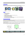
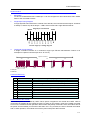
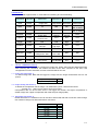
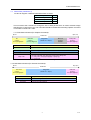
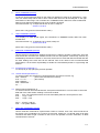
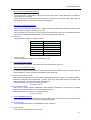
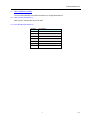
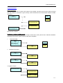
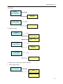
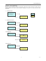
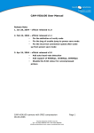
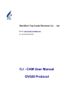
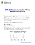
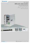
C1182
Video Compression Module
User Manual
Release Note:
st
1 Release : Aug 01, 2012
www.electronics123.com
C1182 USER MANUAL
General Description
This is a series of camera modules which perform video compression and output video stream through
UART port. It can be attached to a wireless host and performing a remote video camera.
Video
Compression
Engine
VGA
Image
Sensor
UART
Host
C1182
System block diagram
Features
Small in size 32x32mm
On board VGA color sensor
Lens included(option)
3.3V Operation
Advance H.264 CODEC provide excellent image at low bit rate
Simple and user friendly command
Interface to external host via RS-232.
UART: 128Kbps max for data transfer
Built-in down sampling, clamping and windowing circuits for VGA(640 x480), QVGA(320x240)
Power saving mode, power on by RS232 trigger
Board Layout and Pin Description
The module consists of 2 boards, sensor and controller board. They are interconnected by using flexible
flat cable. They can be bind together by using 4 screws
Sensor board: it has been designed to be mounted in standard camera house for 32x32mm PCB. Either
14mm or 20mm lens holder can be used. If use C/CS-Mount lens, just remove the lens holder and cover
the holes by any means.
Controller board: it can be mounted on the back of sensor board. The 4pin 1.25mm pitch board
connector is provided for UART cable. Due to the high speed operation, the controller board needs more
space for heat dissipation and therefore the bigger housing will be recommended.
GND
RxD
TxD
VCC
Front View
Pin
Description
VCC
Power 3.3V DC
TxD
Data Transmit (3.3V)
Rear View
RxD
Data Receive (3.3V)
GND
Power Ground
Connector: 1.25 mm pitch, 4 pin single row
2
V1.0
C1182 USER MANUAL
Serial Interface
1.
Baud Rate
C1182 use a settled baud rate 115200 bps. It can be configured to other baud rate at max 128Kb.
Refer to the command set 0x01.
2.
Single Byte Timing Diagram
A single byte RS-232 transmission consists of the start bit, 8-bit contents and the stop bit. A start bit
is always 0, while a stop bit is always 1. LSB is sent out first and is right after the start bit.
Single Byte Transmission
Stop
Bit 7
Bit 6
Bit 5
Bit 4
Bit 3
Bit 2
Bit 1
Bit 0
Start
RS-232 single byte timing diagram
3.
Command Timing Diagram
A single command consists of 6 continuous single byte RS-232 transmissions. Below is an
example for Capture Command (AA 05 01 FF FF FF)
Capture Command
AA
PS
05
PS
01
PS
FF
PS
FF
PS
FF
PS
P
P=Stop bit
S=Start bit
Command Summary
1
2
3
4
5
6
7
8
9
10
11
INITIAL
DATE
TIME
PREVIEW
CAPTURE
DATA LENGTH
GET DATA
SYNC
POWER CONTROL
ACK
NAK
To configure the image size, quality, baud rate and packet size
Send from Host the Date info for stamping purpose
Send from Host the Time info for stamping purpose
Command to get video frame data continuously
Command to take a frame for transmission
Information about the image data length
Get the image data packet from module
Sync the host to the module
Turn off the module, all parameter reset
Command to indicate the communication success
Command to indicate the communication fail with error code
Power control of the module
The module power is controlled by UART. When power is applied to the module and UART cable is
connected, the module will not operate by itself. To power on the module, issue Sync (AA08) command
to turn on the module and start operation. When Power Off (AA09) command is sent, the module will cut
the power and the standby current will be less than 1mA. If by accident, the host to activate the module
and no other operation, the module will consume power until power disconnected.
3
V1.0
C1182 USER MANUAL
Command Set
The C1182 module supports total 11 commands for interfacing to host as following:
Command ID Number
1.
Parameter1
Image Size:
Parameter2
Parameter3
Parameter4
Image Quality Baud Rate
Packet Size:
Initial
AA01H
Date
AA02H
YY
MM
DD
Time
AA03H
hh
mm
ss
Preview
AA04H
I-frame
Interval
Packet
Interval
FFH
Capture
AA05H
FFH
FFH
FFH
Data
Length
AA06H
Get Data
AA07H
START: 01H
STOP: 00H
I-frame: 01H
p-frame: 00H
Length Byte
low
Packet ID
low byte
Sync
AA08H
00H
00H
00H
00H
PWR Ctrl
AA09H
Auto OFF : 01H
Always ON : 00H
ON:01H
OFF: 00H
00H
00H
ACK
AA0Ah
Command ID
ACK counter
FFH
FFH
NAK
AA0Bh
NAK counter
Error Number
FFH
FFH
Length Byte Length Byte
mid
high
Packet ID
FFH
high byte
01H: Stamp
00H: no stamp
01H: Stamp
00H: no stamp
FFH
FFH
INITIAL COMMAND (AA01H)
The host issues this command to configure the image size, quality, baud rate and data packet size.
After receiving this command, the module will send out an ACK command to the host if the
configuration success. Otherwise, an NAK command will be sent out.
1.1 Image Size (Parameter 1)
To define image size. Note that the bigger the image size the longer transmission time for one
picture.
QVGA(320 x 240)
01H
VGA(640 x 480)
02H
1.2 Image Quality (Parameter 2)
To define the compression rate of image. It is divided into 2 parts, I-frame and P-frame.
Format: IPH where I is for I-frame and P for P-frame
Compression rate can be set from 0H-FH. The bigger the number, the higher compression or
smaller image size. Higher compression will result the poor image quality.
1.3
Baud Rate (Parameter 3)
Default baud rate is 115.2Kb but user can set this to other baud rate after connection. After change,
user needs to change host baud rate before connection.
128Kb
115Kb
57.6Kb
38.4Kb
19.2Kb
14.4Kb
9.6K
4
01H
02H
03H
04H
05H
06H
07H
V1.0
C1182 USER MANUAL
1.4
Packet Size (Parameter 4)
C1182 can support 4 different Data Packet Size as below:
512 Bytes
2048 Bytes
4096 Bytes
8192 Bytes
01H
02H
03H
04H
The host issues this command to change the size of data packet which is used to transmit image
data from the C1182 to the host. This command should be issued before sending Capture command
or Get Data command to C1182.
1.4.1 Data Packet Content (For Capture Command):
Byte 0
Byte (N-1)
Packet Size
ID
(2 bytes)
Low byte, high byte
ID
Data Size
Image Data
Reserved
Verify Code
Data Size
(2 bytes)
Low byte, high byte
Image Data
(Packet size – 8 bytes)
Reserved
(2 bytes)
0xFFFF
Verify Code
(2 bytes)
Low byte, high byte
-> Data Packet ID, starts from 0000h to F0F0h
-> Actual size of available image data in the packet
-> Available image data
-> 0xFFFF
-> Error detection code, equals to the lower byte of sum of the whole data packet except
the verify code field. The higher byte of this code is always zero.
i.e. verify code = low byte(sum(byte[0] to byte[N-3]))
N = packet size
Note: The size of the last data packet varies for different image.
1.4.2 Data Packet Content (For Preview Command):
Byte 0
Packet Size
Start Code
(2 bytes)
Low byte, high byte
Image Data
(Packet size – 4 bytes)
Start Code
-> 2-byte start code (0xAA55)
Image Data
-> Available image data
End Code
Byte (N-1)
End Code
(2 bytes)
Low byte, high byte
-> 2-byte end code (0x55AA)
5
V1.0
C1182 USER MANUAL
2.
DATE COMMAND (AA02H)
C1182 can accept date time stamp on the image. By default D/T stamp is off, parameter 4 = 00H
User can select stamp either date or time or both. Data time info will be stamped on the right
hand bottom of the image. This command is in YYMMDD format, differ from other hexadecimal.
Date time info will keep update as long as the module is powered.
Command format: e.g. To input date of Dec 25, 2011, stamp on
AA 02 11 12 25 01
(Note: this is only good for VGA resolution video.)
3.
TIME COMMAND (AA03H)
Time display is in 24Hr format. Again, this command is in HHMMSS format, differ from other
hexadecimal.
Command format: e.g. To input time of 12:30:00, stamp off
AA 03 12 30 00 00
(Note: this is only good for VGA resolution video.)
4.
PREVIEW COMMAND (AA04H)
Host to issue this command for capturing a sequence of I-frame or P-frame continuously. Once the
host issues this command, the module will send out the data packets continuously, without any
handshaking command in between. In this case, the amount of command-data overheads and also
the CPU loading at the host side can be reduced. Due to the nature of this uncontrolled data
transmission, it is the host’s responsibility to handle the received data packet in a right timing and
manner.
4.1
START/STOP (Parameter 1)
To start (01H) or stop (00H) the preview operation
4.2
I-frame Interval (Parameter 2)
To set the number of P-frames to be inserted between successive I-frames, e,g.
00H – IPPPPP …………. (first I-frame and then all P-frames)
01H – I I I I I I I …………. (all I-frames)
02H—IPIPIPIP…….
03H – IPPIPPIPP….
etc …….
4.3
Packet Interval (Parameter 3)
To set the minimum time interval between each packet transmission. It can be used to control the
data rate of the video stream sending out from the module.
00H -- 0 ms. The next packet will be sent out immediately after the current packet is sent.
01H -- ~2*(1) = 2 ms
02H -- ~2*(2) = 4 ms
…..
FEH - ~ 2*(254) = 508 ms
FFH - ~ use system default
5.
CAPTURE COMMAND (AA05H)
Host to issue this command for capture either I-frame or P-frame, such case, video format can be
all I-frame or any combination of I-P frame, such as IPIP, IPPIPP etc. C1182 will send out an ACK
command and Data Length command to the host if the operation success. Otherwise, an NAK
command will be sent out.
6
V1.0
C1182 USER MANUAL
6.
DATA LENGTH COMMAND (AA06H)
C1182 issues this command for telling the host the size of the image data which is ready for
transmitting out to the host.
These three bytes (LOW, MID, HIGH) represent the length of the image data. User needs to
calculate the number of packets by using this length data.
7.
GET DATA COMMAND (AA07H)
The host can issue this command to request image data packet with desired packet ID after
receiving Data Length command from C1182.
7.1
After receiving this command, C1182 will send a data packet to the host. The details about the
content of the data packet please refer to the previous page in the manual.
Packet ID
Data packet ID, starts from 0000h to F0F0h.
Package ID
0000h
0001h
0002h
0003h
……
F0F0h
7.2
Command
AA 06 00 00 FF FF
AA 06 01 00 FF FF
AA 06 02 00 FF FF
AA 06 03 00 FF FF
……
AA 06 F0 F0 FF FF
Packet Number
Number of packet = Image size / (Packet size – 8)
8.
SYNC COMMAND (AA08H)
The host needs to send this command to sync with C1182 when power up.
9.
PWR CTRL COMMAND (AA09)
C1182 has no sleep mode but auto off mode to save power. By default it is auto off mode, user can
turn this mode on or off by setting the parameter of this command.
9.1 Turn on/off the auto off mode
The module has built in timer to turn off itself if system idle more than 30sec. To turn off this feature,
issue this command and set parameter 1 to 00H, such case, the module will be ON forever until
power removed or receiving force power off command.
Command format: e.g. Turn off the auto off feature
AA 09 00 01 00 00
9.2 Power off the module
User can turn off the module immediately after operation completed to save power by sending
parameter 2 of 00H. It doesn’t care what the power mode is.
Command format: e.g. Turn off the module any time
AA 09 xx 00 00 00
10.
ACK COMMAND (AA0AH)
This command indicates the success of last operation. After receiving any valid command, ACK
command must be sent out except when getting image data.
10.1 Command ID
The command with that ID is acknowledged by this command.
10.2 ACK Counter
ACK counter, indicates the amount of ACK
7
V1.0
C1182 USER MANUAL
11.
NAK COMMAND (AA0BH)
This command indicates corrupted transmission or unsupported features.
11.1 NAK Counter (Parameter 1)
NAK counter, indicates the amount of NAK
11.2 Error Number (Parameter 2)
Number
Description
01H
Parameter 1 error
02H
Parameter 2 error
03H
Parameter 3 error
04H
Parameter 4 error
05H
Command ID error
06H
Picture not ready
07H
Packet ID error
8
V1.0
C1182 USER MANUAL
Command Protocol
SYNC Command
Before the host to talk to module, host needs to send SYNC command until receiving ACK command
from the module. If connection is good, usually, ACK command will be received within 10times of SYNC
command
SYNC
AA 08 00 00 00 00
HOST
:
:
:
C1182
ACK
(AA 0A 08 01 FF FF)
SYNC
(AA 08 00 00 00 00)
ACK
AA 0A 08 02 FF FF
Synchronize complete.
Example 1 – capture a QVGA image
Below is an example of getting a QVGA image, at baud rate 115Kb, packet size of 2KB with date/time
stamping on the picture, power off the module after completion.
1.
Initial Command
Initial
QVGA, i-Q 8, p-Q 8,
115K, 2048 bytes
(AA 01 01 88 02 02)
HOST
ACK
(AA 0A 01 01 FF FF)
2.
C1182
Date/time Command
Date
(AA 02 11 12 25 01)
ACK
(AA 0A 02 02 FF FF)
Time
(AA 03 12 30 00 01)
ACK
(AA 0A 03 03 FF FF)
3. Capture I frame
Capture
(AA 05 01 FF FF FF)
ACK
(AA 0A 05 04 FF FF)
Data Length
(AA 06 ~~ ~~ ~~ FF)
9
V1.0
C1182 USER MANUAL
4. Get Data
Get Data
Packet ID: 0001h
(AA 07 01 00 FF FF)
Data Packet
( 2048 bytes)
:
:
Get Last Data
Packet ID: XXXXh
(AA 07 XX XX FF FF)
Last Data Packet
5. Capture P-frame
Capture
(AA 05 00 FF FF FF)
ACK
(AA 0A 05 xx FF FF)
Data Length
(AA 06 ~~ ~~ ~~ FF)
Get Data
Packet ID: 0001h
(AA 07 01 00 FF FF)
Data Packet
( 2048 bytes)
:
:
Get Last Data
Packet ID: XXXXh
(AA 07 XX XX FF FF)
Last Data Packet
6 Repeat 4 or 5 to get more I-frame or P-frame
7 Power off the module
PWR CRT
(AA 09 xx 00 00 01)
ACK
(AA 0A 08 xx FF FF)
Turn off module
10
V1.0
C1182 USER MANUAL
Example 2 – Preview VGA image
Below is another example to preview a VGA image, at baud rate 115Kb, packet size of 2KB, insert 30
P-frame between two I-frames, without date/time stamping on the picture, and stop the preview after
some time.
1. Initial Command
Initial
VGA, i-Q 8, p-Q 8,
115K, 2048 bytes
(AA 01 02 88 01 02)
HOST
ACK
(AA 0A 01 01 FF FF)
C1182
2. Date/time Command
Date
(AA 02 xx xx xx 00)
ACK
(AA 0A 02 02 FF FF)
Time
(AA 03 xx xx xx 00)
ACK
(AA 0A 03 03 FF FF)
3. Start Preview
Preview Start
(AA 04 01 31 FF FF)
ACK
(AA 0A 04 04 FF FF)
Data Packet
( 2048 bytes)
:
:
4. Stop Preview
Preview Stop
(AA 04 00 xx FF FF)
ACK
(AA 0A 04 05 FF FF)
11
V1.0