1
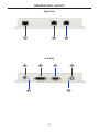
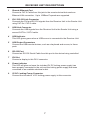
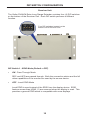
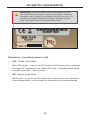
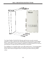
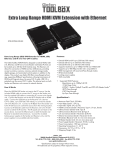
DVIKVM
Extra Long Range
Extender
GTB-DVIKVM-ELR
GTB-DVIKVM-ELR-BLK
User Manual
www.gefentoolbox.com
ASKING FOR ASSISTANCE
Technical Support:
Telephone
(818) 772-9100
Fax(818) 772-9120
Technical Support Hours:
8:00 AM to 5:00 PM Monday thru Friday.
Write To:
Gefen LLC
c/o Customer Service
20600 Nordhoff St
Chatsworth, CA 91311
www.gefen.com
[email protected]
Notice
Gefen LLC reserves the right to make changes in the hardware, packaging and
any accompanying documentation without prior written notice.
DVIKVM Extra Long Range Extender
is a trademark of Gefen LLC
© 2014 Gefen LLC, All Rights Reserved.
All trademarks are the property of their respective owners.
Rev A4
CONTENTS
1
Introduction
2
Operation Notes
3
Features
4
Sender Unit Layout
5
Sender Unit Descriptions
6
Receiver Unit Layout
7
Receiver Unit Descriptions
8
Connecting and Operating the DVIKVM Extra Long Range Extender
9
DIP Switch Configuration
13 Firmware Update
14 Network Cable Wiring Diagram
15 Mounting Plate Installation
16 Specifications
17Warranty
INTRODUCTION
Congratulations on your purchase of the GefenToolBox DVIKVM Extra Long
Range Extender. Your complete satisfaction is very important to us.
About Gefen
We specialize in total integration for your home theater, while also focusing on
going above and beyond customer expectations to ensure you get the most from
your hardware. We invite you to explore our distinct product line. Please visit
http://www.gefen.com for the latest offerings in High-Definition signal solutions or
call us between the hours of 8:00 am and 5:00 pm Monday-Friday, Pacific
Standard Time for assistance with your A/V needs. We’ll be happy to assist you.
Why GefenToolBox?
The GefenToolBox line offers portable and easy-to-install solutions for common
A/V system integration setups using DVI and HDMI connectivity. GefenToolBox
products are wall-mountable and small in size. GefenToolBox products are easily
transported in the field and are ready for immediate and simple installations in
working environments. These products come finished in a glossy color to blend in
with either a white wall or black cabinet.
The GefenToolBox DVIKVM Extra Long Range Extender
The DVIKVM ELR extender extends any DVI, Ethernet, RS-232, and USB source
from a computer to a monitor, touch screen display, or other digital signage application over a distance up to 330 feet (100 meters) using two Cat-5 cables.
USB 2.0 data rates up to 480 Mbps are supported in addition to backward-compatibility with USB 1.1. The Receiver Unit allows the connections of up to two (2)
USB devices, providing access to printers, scanners, cameras, external storage
media, digital signage, and automated control systems.
This product uses Gefen ELR technology, allowing DVI, Ethernet, and RS-232
signals to travel along the same Cat-5 cable, reducing cabling costs and providing easier installation. A second Cat-5 cable is used for USB extension.
How It Works
Place the DVIKVM ELR Sender Unit next to the DVI source. Use the included
DVI cable to connect the computer or other DVI source to the Sender Unit. Use
the supplied USB cable to connect the USB host (source) device to the USB port
on the Sender Unit. Connect the Receiver Unit to the monitor or digital signage
display with a DVI cable. Connect the USB devices to the Receiver Unit. Use two
Cat-5 cables, up to 330 feet (100 meters), to connect the Sender Unit to the
Receiver Unit. Connect the included locking power supplies to the Sender Unit
and Receiver Unit, and then connect both power cords to available electrical
outlets.
1
OPERATION NOTES
PLEASE READ THESE NOTES BEFORE INSTALLING OR
OPERATING THE DVIKVM EXTRA LONG RANGE EXTENDER
•
CAT-5 or CAT-6 cables should not exceed 330 feet (100 meters).
•
Shielded (STP) CAT-5 or CAT-6 is recommended. However, un-shielded
(UTP) CAT-5 or CAT-6 is acceptable.
NOTE: The shielded cable has an advantage by providing immunity to
Electromagnetic Interference (EMI), cell phones and A/C motors.
•
The GefenToolBox DVIKVM Extra Long Range Extender Over One CAT5
features the ability to generate compatible EDID and Hot Plug signals when
working with different brands of source devices and monitors.
2
FEATURES
Features
•
Supports DVI resolutions up to 1920x1200 @ 60 Hz or 1080p at 330 feet
(100 meters)
•
Extends USB 2.0 up to 330 feet (100 meters)
•
Supports USB 2.0 480 Mbps
•
Backward-compatible with USB 1.1 devices
•
Extends Ethernet and RS-232 signals
•
Works with PC and Mac computers
•
Locking Power Supplies
•
Wall-mountable
Package Includes
(1)
(1)
(1)
(1)
(2)
(1)
GefenToolBox DVIKVM Extra Long Range Extender - Sender Unit
GefenToolBox DVIKVM Extra Long Range Extender - Receiver Unit
6 ft. DVI Cable (M-M)
6 ft. USB cable (A-B)
5V DC Locking Power Supplies
Quick-Start Guide
3
SENDER UNIT LAYOUT
Right Side
1
2
3
Left Side
4
6
7
5
9
8
4
SENDER UNIT DESCRIPTIONS
1
USB Link Connector
Connects the USB signals from the Sender Unit to the Receiver Unit using CAT5e / CAT-6 cable.
2
DVI / RS-232 Link Connector
Connects the DVI and RS-232 signals from the Sender Unit to the Receiver Unit
using CAT-5e / CAT-6 cable.
3
Ethernet Input
Connect a CAT-5 cable from a port on a local Ethernet switch to this jack. The
DVIKVM-ELR supports 10/100BaseT Ethernet.
4
5 V DC Locking Power Connector
Connect the included 5 V DC locking power supply to this connector.
5
Power Indicator
This LED will glow red once the included 5V DC locking power supply has
been properly connected to the unit and the locking power supply has been
connected to an available electrical outlet.
6
DVI In
Connect a DVI cable from the computer to this DVI-I connector.
7
RS-232 Port
Connect a RS-232 Serial Cable from the RS-232 host device to this port.
8
USB Indicator
This LED glows green when a USB device is connected to the Sender Unit.
9
USB In
Connects the Sender Unit to the computer using a USB cable.
5
RECEIVER UNIT LAYOUT
Right Side
1
2
3
Left Side
4
6
7
5
8
9
6
RECEIVER UNIT DESCRIPTIONS
1
Remote Ethernet Port
Connect a CAT-5 Cable from this jack to the remote device that needs an
Ethernet LAN connection. Up to 100BaseT speeds are supported.
2
DVI / RS-232 Link Connector
Connects the DVI and RS-232 signals from the Receiver Unit to the Sender Unit
using CAT-5e / CAT-6 cable.
3
USB Link Connector
Connects the USB signals from the Receiver Unit to the Sender Unit using a
second CAT-5e / CAT-6 cable.
4
USB Indicator
This LED glows green when a USB source is connected to the Receiver Unit.
5
USB Output Connectors
Connect the USB remote devices, such as a keyboard and mouse, to these
ports.
6
RS-232 Port
Connect an RS-232 Serial Cable from this port to the device being controlled.
7
DVI Out
Connect a display to this DVI-I connector.
8
Power Indicator
This LED will glow red once the included 5V DC locking power supply has
been properly connected to the unit and the locking power supply has been
connected to an available electrical outlet.
9
5V DC Locking Power Connector
Connect the included 5 V DC locking power supply to this connector.
7
CONNECTING AND OPERATING
THE DVIKVM EXTRA LONG RANGE EXTENDER
How to Connect the DVIKVM Extra Long Range Extender
1. Connect the computer DVI output to the Sender Unit using the provided DVI
cable. Connect the monitor to the Receiver Unit using a DVI cable.
2. Connect the included USB cable from the computer to the Sender Unit.
3. Connect the USB devices to the Receiver Unit.
4. Connect the Ethernet port on the Sender Unit to an Ethernet source.
5. Connect the Ethernet port on the Receiver Unit to the Ethernet (LAN) port on
the display device.
6. Connect the RS-232 ports to the host and display devices.
7. Connect CAT-5e or CAT-6 cables between the Link ports on the Sender Unit
and the Link ports on the Receiver Unit.
NOTE: If terminating network cables in the field, please adhere to the TIA/
EIA568B specification (see page 14).
5. Connect the 5V DC locking power supplies to the Sender Unit and Receiver
Unit. Do not overtighten the locking connectors. Plug the two (2) AC power
cords from the power supplies to available electrical outlets.
Wiring Diagram for the DVIKVM Extra Long Range Extender Over One CAT5
CAT-5 LINK CABLE / ETHERNET
(Up to 330 ft)
RS-232 CABLE
USB CABLE
DVI CABLE
100BASE-T Router
or Ethernet switch
DVI Source
Computer
Receiver
Sender
USB External HDD
Monitor or Kiosk Touchscreen Display
GTB-DVIKVM-ELR
8
DIP SWITCH CONFIGURATION
Sender Unit
The Gefen DVIKVM Extra Long Range Extender contains DIP switches on the
bottom of the Sender Unit. Each DIP switch performs a different function.
Two DIP switches located on
the bottom of the Sender Unit.
DIP Switch 1 - Power Management (Default = ON)
•
OFF - Enable Green Mode
When DIP switch 1 is set to the OFF position, the Sender unit is powered
only when 5V is present on the HDMI / DVI cable. Automatic Power Mode
consumes less than 1 Watt of power.
•
ON - Disable Green Mode
If DIP switch 1 is set to the ON position, then the Sender unit is placed in
Power Always Mode. In this mode, the Receiver unit is always powered.
DIP Switch 2 - RS-232 Mode (Default = OFF)
•
OFF - Pass-through Mode
Pass-through mode for RS-232. This is default position.
•
ON - Firmware Upgrade Mode
Firmware Upgrade mode (See page 13 for instructions). Both DIP switches
(1 and 2) must be set to the ON position to perform a firmware upgrade.
If DIP switch 2 is in the ON position, RS-232 cannot be extended.
9
DIP SWITCH CONFIGURATION
Receiver Unit
The Gefen DVIKVM Extra Long Range Extender contains four (4) DIP switches
on the bottom of the Receiver Unit. Each DIP switch performs a different
function.
Four DIP switches located on the
bottom of the Receiver Unit.
DIP Switch 1 - EDID Mode (Default = OFF)
•
ON - Pass-Through Mode
DDC and HPD are passed through. Both the connection status and the full
video capabilities of the monitor are used by the source device.
•
OFF - Local EDID Mode
Local EDID is used instead of the EDID from the display device. EDID
features newer than HDMI 1.3 are removed when the display is read. This
provides a general EDID which is compatible with more displays.
10
DIP SWITCH CONFIGURATION
DIP Switch 2 - Hot Plug Detect (Default = OFF)*
•
ON - HPD Pass-Through
HPD follows upstream HPD towards the source. The HPD signal will reflect
the connection status between the display device and the source device. If
the source or monitor is temporarily disconnected then reconnected, there
will be a delay of 20 - 30 seconds before the content is restored to the
monitor.
•
OFF - HPD Always High
The HPD signal remains high regardless of the downstream HPD state.
If the source or monitor does not properly handle HPD (no picture after
connecting / reconnecting source or display), set this DIP switch to the OFF
position.
DIP Switch 3 - Supports DVI Connections (Default = ON)*
•
ON - Disable HDCP
If a DVI connection is used, set DIP 3 to the ON position. DVI is supported
by disabling HDCP pass-through.
•
OFF - Enable HDCP
If an HDMI device is connected, set DIP 3 in the OFF position.
*DIP switch is only operational when using Local EDID (DIP 1 = OFF).
11
DIP SWITCH CONFIGURATION
IMPORTANT: The Green Mode feature on the Receiver unit is
not implemented on hardware versions prior to 9502. Check the
hardware version, printed on the bottom of the Receiver unit. For
example, the sample image below indicates hardware version
9401 which does not have the Green Mode feature.
DIP Switch 4 - Green Mode (Default = ON)
•
OFF - Enable Green Mode
When DIP switch 1 is set to the OFF position, the Receiver unit is powered
only when 5V is present on the HDMI / DVI cable. Automatic Power Mode
consumes less than 1 Watt of power.
•
ON - Disable Green Mode
If DIP switch 1 is set to the ON position, then the Receiver unit is placed in
Power Always Mode. In this mode, the Receiver unit is always powered.
12
FIRMWARE UPDATE
Updating the Firmware
STOP: Before beginning the update process, disconnect the
Sender unit from the Receiver unit.
1. Connect an RS-232 cable from the computer to the Sender Unit.
2. Set all DIP switches on the Sender unit to the ON position.
3. Connect the 5V DC locking power supply to the Sender Unit.
4. Go to the directory where the firmware files are stored.
5. Double-click the .BAT file. A screen similar to the following will appear:
Found sink on port 4
Autodetect platform: full sink
Autodetect platform: spi.
Autodetect size: 128k
Erasing Eeprom....Done.
progress: 100%
Total bytes: 38804. Total time: 99.906000 seconds
Burn succeeded.
Verifying file...
progress: 100%
Total bytes: 38804. Total time: 88.266000 seconds
Verification succeeded!!!
6. Return both DIP switches on the Sender unit to the OFF position.
7. To update the firmware on the Receiver unit, set ALL DIP switches on the
Receiver unit to the ON position.
8. Connect the 5V DC locking power supply to the Receiver unit.
9. Repeat steps 4 and 5.
10. The firmware update process is complete.
13
NETWORK CABLE WIRING DIAGRAM
Gefen recommends the TIA/EIA-568-B wiring option. Please adhere to the table
below when field terminating cable for use with Gefen products.
Pin
Color
1
Orange / White
2
Orange
3
Green / White
4
Blue
5
Blue / White
6
Green
7
Brown / White
8
Brown
12345678
CAT-5, CAT-5e, and CAT-6 cabling comes in stranded and solid core types.
Gefen recommends using solid core cabling.
It is recommended to use one continuous run from one end to the other. In some
cases, connecting through a patch might not work.
14
WALL MOUNTING INSTRUCTIONS
The GefenToolBox DVIKVM ELR Sender and Receiver may be mounted
vertically in a wall or cabinet with wood/drywall screws as shown in the diagram
above. There should be an inch or two of clearance between the edges of the
unit and any walls or vertical surfaces to allow for enough clearance for insertion
and retraction of cables at the DVI and RS-232 connectors.
For installation on a drywall surface, use a #6 drywall screw. It is recommended
when installing on a drywall surface that studs be used to secure the Splitter
should undue stress be applied when connecting and disconnecting HDMI
cables.
15
SPECIFICATIONS
Maximum Pixel Clock................................................................................165 MHz
Maximum TMDS Pixel Clock.....................................................................165 MHz
DVI Connectors (Sender / Receiver)................................DVI-I 29-pin (digital only)
USB Connector (Sender Unit).................................................................(1) Type B
USB Connectors (Receiver Unit).............................................................(2) Type A
Link Connectors (Sender / Receiver)........................................................(2) RJ-45
Ethernet Connectors (Sender / Receiver)...............................(2) RJ-45 (1 per unit)
RS-232 Connector (Sender)...............................................................DB-9, female
RS-232 Connector (Receiver)................................................................DB-9, male
RS-232 Baud Rate..................................................................................19200 bps
Power Supply (Sender / Receiver)................................................................5V DC
Power Consumption................................................................10 W per unit (max.)
Operating Temperature..............................................................................0 - 40 °C
Dimensions.........................................................................3.3” W x 6.7” H x 1.2” D
Shipping Weight..............................................................................................6 lbs.
15
WARRANTY
Gefen warrants the equipment it manufactures to be free from defects in material
and workmanship.
If equipment fails because of such defects and Gefen is notified within two (2)
years from the date of shipment, Gefen will, at its option, repair or replace the
equipment, provided that the equipment has not been subjected to mechanical,
electrical, or other abuse or modifications. Equipment that fails under conditions
other than those covered will be repaired at the current price of parts and labor in
effect at the time of repair. Such repairs are warranted for ninety (90) days from
the day of reshipment to the Buyer.
This warranty is in lieu of all other warranties expressed or implied, including
without limitation, any implied warranty or merchantability or fitness for any
particular purpose, all of which are expressly disclaimed.
1. Proof of sale may be required in order to claim warranty.
2. Customers outside the US are responsible for shipping charges to and from
Gefen.
3. Copper cables are limited to a 30 day warranty and cables must be in their
original condition.
The information in this manual has been carefully checked and is believed to
be accurate. However, Gefen assumes no responsibility for any inaccuracies
that may be contained in this manual. In no event will Gefen be liable for
direct, indirect, special, incidental, or consequential damages resulting from
any defect or omission in this manual, even if advised of the possibility of such
damages. The technical information contained herein regarding the features and
specifications is subject to change without notice.
For the latest warranty coverage information, refer to the Warranty and Return
Policy under the Support section of the Gefen Web site at www.gefen.com.
PRODUCT REGISTRATION
Please register your product online by visiting the Register Product page
under the Support section of the Gefen Web site.
16
Rev A4
20600 Nordhoff St., Chatsworth CA 91311
1-800-545-6900
818-772-9100
www.gefen.com
Pb
This product uses UL listed or CE compliant power supplies.
fax: 818-772-9120
[email protected]