1
52012-008-01 FrontCov Page 1 Monday, November 20, 2000 5:24 PM
Instruction Bulletin
52012-008-01B
November 2000
Raleigh, NC, USA
ALTIVAR® 18 Adjustable Speed
Drive Controllers for
Asynchronous Motors
User’s Manual
Retain for future use.
52012-008-01 FrontCov Page 2 Monday, November 20, 2000 5:24 PM
ALTIVAR 18 Drive Controller
User’s Manual
52012-008-01B
November 2000
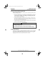
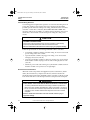
DANGER
HAZARDOUS VOLTAGE.
• Read and understand this bulletin in its entirety before installing or
operating ALTIVAR 18 drive controllers. Installation, adjustment, repair,
and maintenance of these drive controllers must be performed by
qualified personnel.
• Disconnect all power before servicing drive controller. WAIT ONE
MINUTE until DC bus capacitors discharge, then measure DC bus
capacitor voltage (see pages 39 and 40) to verify DC voltage is less than
45 V. The DC bus LED is not an accurate indication of the absence of DC
bus voltage.
• DO NOT short across DC bus capacitors or touch unshielded
components or terminal strip screw connections with voltage present.
• Install all covers before applying power or starting and stopping the drive
controller.
• User is responsible for conforming to all applicable code requirements
with respect to grounding all equipment. For drive controller grounding
points, refer to Figure 5 on page 11.
• Many parts in this drive controller, including printed wiring boards, operate
at line voltage. DO NOT TOUCH. Use only electrically insulated tools.
Before servicing drive controller:
• Disconnect all power.
• Place a “DO NOT TURN ON” label on drive controller disconnect.
• Lock disconnect in open position.
Failure to follow these instructions will result in death or serious injury.
© 1997–2000 Schneider Electric All Rights Reserved.
Electrical equipment should be serviced only by qualified personnel. No responsibility is assumed by
Schneider Electric for any consequences arising out of the use of this material.
52012-008-01 TOC Page i Monday, November 20, 2000 5:27 PM
52012-008-01B
November 2000
ALTIVAR 18 Drive Controller
Table of Contents
TABLE OF CONTENTS
RECEIVING AND PRELIMINARY INSPECTION . . . . . . . . . . . . . . . . . . . . . . . . . . . . . . 1
STORING AND SHIPPING . . . . . . . . . . . . . . . . . . . . . . . . . . . . . . . . . . . . . . . . . . . . . . . 1
TECHNICAL CHARACTERISTICS . . . . . . . . . . . . . . . . . . . . . . . . . . . . . . . . . . . . . . . . . 2
SPECIFICATIONS. . . . . . . . . . . . . . . . . . . . . . . . . . . . . . . . . . . . . . . . . . . . . . . . . . . . . . 4
DIMENSIONS . . . . . . . . . . . . . . . . . . . . . . . . . . . . . . . . . . . . . . . . . . . . . . . . . . . . . . . . . 5
ATV18 FAN FLOW RATES . . . . . . . . . . . . . . . . . . . . . . . . . . . . . . . . . . . . . . . . . . . . . . . 5
INSTALLATION PRECAUTIONS . . . . . . . . . . . . . . . . . . . . . . . . . . . . . . . . . . . . . . . . . . 6
MOUNTING IN TYPE 12 (IP54) METAL ENCLOSURE . . . . . . . . . . . . . . . . . . . . . . . . . 7
Calculating Enclosure Size . . . . . . . . . . . . . . . . . . . . . . . . . . . . . . . . . . . . . . . . . . . . 7
Ventilation . . . . . . . . . . . . . . . . . . . . . . . . . . . . . . . . . . . . . . . . . . . . . . . . . . . . . . . . . 8
ELECTROMAGNETIC COMPATIBILITY (EMC) . . . . . . . . . . . . . . . . . . . . . . . . . . . . . . . 9
Installation precautions for meeting EN55011 Class A . . . . . . . . . . . . . . . . . . . . . . . 9
General rules . . . . . . . . . . . . . . . . . . . . . . . . . . . . . . . . . . . . . . . . . . . . . . . . . . . 9
Installation Plan. . . . . . . . . . . . . . . . . . . . . . . . . . . . . . . . . . . . . . . . . . . . . . . . . . 9
WIRING . . . . . . . . . . . . . . . . . . . . . . . . . . . . . . . . . . . . . . . . . . . . . . . . . . . . . . . . . . . . . 11
General Wiring Practices. . . . . . . . . . . . . . . . . . . . . . . . . . . . . . . . . . . . . . . . . . . . . 12
Branch Circuit Connections. . . . . . . . . . . . . . . . . . . . . . . . . . . . . . . . . . . . . . . . . . . 12
Output Wiring Precautions . . . . . . . . . . . . . . . . . . . . . . . . . . . . . . . . . . . . . . . . . . . 13
Grounding . . . . . . . . . . . . . . . . . . . . . . . . . . . . . . . . . . . . . . . . . . . . . . . . . . . . . . . . 14
Power Terminals . . . . . . . . . . . . . . . . . . . . . . . . . . . . . . . . . . . . . . . . . . . . . . . . . . . 15
Equipment Ground Terminal . . . . . . . . . . . . . . . . . . . . . . . . . . . . . . . . . . . . . . . . . . 16
Control Terminals . . . . . . . . . . . . . . . . . . . . . . . . . . . . . . . . . . . . . . . . . . . . . . . . . . 17
USING THE LOGIC INPUTS. . . . . . . . . . . . . . . . . . . . . . . . . . . . . . . . . . . . . . . . . . . . . 18
USING THE ANALOG INPUTS . . . . . . . . . . . . . . . . . . . . . . . . . . . . . . . . . . . . . . . . . . . 20
FUNCTION COMPATIBILITY . . . . . . . . . . . . . . . . . . . . . . . . . . . . . . . . . . . . . . . . . . . . 21
WIRING DIAGRAM . . . . . . . . . . . . . . . . . . . . . . . . . . . . . . . . . . . . . . . . . . . . . . . . . . . . 22
FAULT RELAY. . . . . . . . . . . . . . . . . . . . . . . . . . . . . . . . . . . . . . . . . . . . . . . . . . . . . . . . 22
RECOMMENDED FUSES. . . . . . . . . . . . . . . . . . . . . . . . . . . . . . . . . . . . . . . . . . . . . . . 23
THERMAL OVERLOAD PROTECTION . . . . . . . . . . . . . . . . . . . . . . . . . . . . . . . . . . . . 24
AVAILABLE TORQUE . . . . . . . . . . . . . . . . . . . . . . . . . . . . . . . . . . . . . . . . . . . . . . . . . . 25
FACTORY SETTINGS. . . . . . . . . . . . . . . . . . . . . . . . . . . . . . . . . . . . . . . . . . . . . . . . . . 26
USING THE DISPLAY KEYPAD . . . . . . . . . . . . . . . . . . . . . . . . . . . . . . . . . . . . . . . . . . 27
PARAMETER SUMMARY . . . . . . . . . . . . . . . . . . . . . . . . . . . . . . . . . . . . . . . . . . . . . . . 28
© 1997–2000 Schneider Electric All Rights Reserved
i
52012-008-01 TOC Page ii Monday, November 20, 2000 5:27 PM
ALTIVAR 18 Drive Controller
Table of Contents
52012-008-01B
November 2000
DRIVE CONTROLLER SET UP . . . . . . . . . . . . . . . . . . . . . . . . . . . . . . . . . . . . . . . . . . 30
Level 1 Parameters . . . . . . . . . . . . . . . . . . . . . . . . . . . . . . . . . . . . . . . . . . . . . . . . . 30
Level 2 Parameters . . . . . . . . . . . . . . . . . . . . . . . . . . . . . . . . . . . . . . . . . . . . . . . . . 33
MAINTENANCE. . . . . . . . . . . . . . . . . . . . . . . . . . . . . . . . . . . . . . . . . . . . . . . . . . . . . . . 38
PRECAUTIONS . . . . . . . . . . . . . . . . . . . . . . . . . . . . . . . . . . . . . . . . . . . . . . . . . . . . . . . 38
Procedure 1: Bus Voltage Measurement. . . . . . . . . . . . . . . . . . . . . . . . . . . . . . . . . 39
Drive Controllers ATV18•••M2 and ATV18U18N4 to D12N4 . . . . . . . . . . . . . . 39
Drive Controllers ATV18D16N4 and ATV18D23N4 . . . . . . . . . . . . . . . . . . . . . 40
Procedure 2: Checking Supply Voltage. . . . . . . . . . . . . . . . . . . . . . . . . . . . . . . . . . 41
Procedure 3: Checking the Peripheral Equipment . . . . . . . . . . . . . . . . . . . . . . . . . 41
Fault Storage . . . . . . . . . . . . . . . . . . . . . . . . . . . . . . . . . . . . . . . . . . . . . . . . . . . . . . 42
FAULT CODES . . . . . . . . . . . . . . . . . . . . . . . . . . . . . . . . . . . . . . . . . . . . . . . . . . . . . . . 42
INDEX . . . . . . . . . . . . . . . . . . . . . . . . . . . . . . . . . . . . . . . . . . . . . . . . . . . . . . . . . . . . . . 45
ii
© 1997–2000 Schneider Electric All Rights Reserved
52012-008-01 doc Page 1 Monday, November 20, 2000 5:28 PM
52012-008-01B
November 2000
ALTIVAR 18 Drive Controller
Receiving & Preliminary Inspection
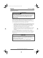
RECEIVING AND PRELIMINARY INSPECTION
Before installing the ALTIVAR® 18 (ATV18) drive controller, read this manual
and follow all precautions:
• Before removing the drive controller from its packing material, verify it is
not damaged from shipping. Any damage to the packing carton usually
indicates improper handling. If any damage is found, notify the carrier
and your Square D representative.
• After removing the drive controller from its packaging, visually inspect
the exterior for shipping damage. If any shipping damage is found, notify
the carrier and your sales representative.
• Verify that the drive controller nameplate and label conform to the packing
slip and corresponding purchase order.
CAUTION
EQUIPMENT DAMAGE HAZARD
Do not operate or install any drive controller that appears damaged.
Failure to follow this instruction can result in injury or equipment damage.
STORING AND SHIPPING
If the drive controller is not being immediately installed, store it in a clean, dry
area where the ambient temperature is between -25 and +65 °C (-13 to +149 °F).
If the drive controller must be shipped to another location, use the original
shipping material and carton to protect the drive controller.
© 1997–2000 Schneider Electric All Rights Reserved
1
52012-008-01 doc Page 2 Monday, November 20, 2000 5:28 PM
ALTIVAR 18 Drive Controller
Technical Characteristics
52012-008-01B
November 2000
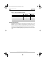
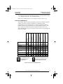
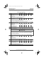
TECHNICAL CHARACTERISTICS
Table 1:
Drive Controller
Catalog Number
[1]
[2]
2
Motor Power
Rated
Output
Current
(In)
Transient
Output
Current [2]
Total
Dissipated
Power @
Rated Load
Short
Circuit
Rating
A
A
kW
hp
A
A
W
A rms sym.
4.4
3.9
0.37
0.5
2.1
3.2
23
1,000
ATV18U18M2
7.6
6.8
0.75
1
3.6
5.4
39
1,000
ATV18U29M2
13.9
12.4
1.5
2
6.8
10.2
60
1,000
ATV18U41M2
19.4
17.4
2.2
3
9.6
14.4
78
1,000
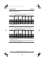
Values correspond to the amount absorbed by drive controllers supplied by mains with fault capacity equal
to short-circuit rating indicated in table and under nominal conditions of load and speed of the associated
motor, without additional inductance.
For 60 seconds.
Drive Controller
Catalog Number
[2]
[3]
Input Line
Current [1]
Single Phase
200 V 240 V
ATV18U09M2
Table 2:
[1]
Technical Characteristics: 200 V -15% to 240 V +10%, 50/60 Hz ±5%,
Single-Phase Input, Three-Phase Output
Technical Characteristics: 200 -15% to 230 V +10%, 50/60 Hz ±5%,
Three-Phase Input, Three-Phase Output
Input Line
Current [1]
Three Phase
200 V 230 V
Motor Power
Rated
Output
Current
(In)
Transient
Output
Current [2]
Total
Dissipated
Power @
Rated Load
Short
Circuit
Rating
A
A
kW
hp
A
A
W
A rms sym.
ATV18U54M2
16.2
14.9
3
-
12.3
18.5
104
5,000
ATV18U72M2
20.4
18.8
4
5
16.4 [3]
24.6
141
5,000
ATV18U90M2
28.7
26.5
5.5
7.5
22 [3]
33
200
22,000
ATV18D12M2
38.4
35.3
7.5
10
28 [3]
42
264
22,000
Values correspond to the amount absorbed by drive controllers supplied by mains with fault capacity equal
to short-circuit rating indicated in table and under nominal conditions of load and speed of the associated
motor, without additional inductance.
For 60 seconds.
Rated output currents shown are for switching frequencies of 2.2 to 4 kHz. If switching frequency is > 4 kHz
and ≤ 8 kHz, derate output current by 5%. If switching frequency is > 8 kHz, derate output current by 10%.
See page 37 for adjustment of switching frequency.
© 1997–2000 Schneider Electric All Rights Reserved
52012-008-01 doc Page 3 Monday, November 20, 2000 5:28 PM
52012-008-01B
November 2000
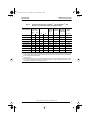
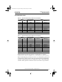
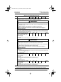
Table 3:
Drive Controller
Catalog Number
[1]
[2]
[3]
[4]
ALTIVAR 18 Drive Controller
Technical Characteristics
Technical Characteristics: 380/220 V [1] -15% to 460/270 V [1] +10%,
50/60 Hz ±5%, Three-Phase Input, Three-Phase Output
Input Line
Current [2]
Three Phase
380 V 460 V
Motor Power
Rated
Output
Current
(In) [4]
Transient
Output
Current [3]
Total
Dissipated
Power @
Rated Load
Short
Circuit
Rating
A
A
kW
hp
A
A
W
A rms sym.
ATV18U18N4
2.9
2.7
0.75
1
2.1
3.2
24
5,000
ATV18U29N4
5.1
4.8
1.5
2
3.7
5.6
34
5,000
ATV18U41N4
6.8
6.3
2.2
3
5.3
8
49
5,000
5,000
ATV18U54N4
9.8
8.4
3
-
7.1
10.7
69
ATV18U72N4
12.5
10.9
4
5
9.2
13.8
94
5,000
ATV18U90N4
16.9
15.3
5.5
7.5
11.8
17.7
135
22,000
ATV18D12N4
21.5
19.4
7.5
10
16
24
175
22,000
ATV18D16N4
31.8
28.7
11
15
22
33
261
22,000
ATV18D23N4
42.9
38.6
15
20
29.3
44
342
22,000
Suitable for use on neutral grounded systems only.
Values correspond to the amount absorbed by drive controllers supplied by mains with fault capacity equal
to short-circuit rating indicated in table and under nominal conditions of load and speed of the associated
motor, without additional inductance.
For 60 seconds.
Rated output currents shown are for switching frequencies of 2.2 to 4 kHz. If switching frequency is > 4 kHz
and ≤ 8 kHz, derate output current by 5%. If switching frequency is > 8 kHz, derate output current by 10%.
See page 37 for adjustment of switching frequency.
© 1997–2000 Schneider Electric All Rights Reserved
3
52012-008-01 doc Page 4 Monday, November 20, 2000 5:28 PM
ALTIVAR 18 Drive Controller
Specifications
52012-008-01B
November 2000
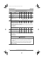
SPECIFICATIONS
Table 4: Specifications
Environment
Degree of Protection
NEMA Open [1]
IP31 without removal of grey tape from the top of the drive controller
IP20 with removal of grey tape from the top of the drive controller
Resistance to vibrations 0.6 g from 10 to 50 Hz
2 g from 50 to 150 Hz
Pollution degree
Pollution degree 2 according to NEMA ICS-1 and IEC 664. Protect the drive
controller against dust, corrosive gas, and falling liquid.
Maximum relative
humidity
93% maximum, non-condensing and without dripping (provide heating system if
there is condensation)
Maximum ambient
temperature
Storage:
Operation:
Altitude
Up to 3,300 ft (1,000 m) without derating;
derate by 3% for each additional 3,300 ft (1,000 m)
-13 to +149 °F (-25 to +65 °C)
+14 to +104 °F (-10 to +40 °C) without grey tape removed
+14 to +122 °F (-10 to +50 °C) with grey tape removed
Electrical Characteristics
Input voltage
ATV18•••M2, 1-phase: 200 V -15% to 240 V +10%
ATV18•••M2, 3-phase: 200 V -15% to 230 V +10%
ATV18•••N4: 380 V -15% to 460 V +10%
Input frequency
50/60 Hz ±5%
Input phases
ATV18U09M2 to U41M2: 1
ATV18U54M2 to D12M2: 3
ATV18•••N4: 3
Output voltage
Maximum voltage equal to input voltage
Output frequency
0.5 to 320 Hz
Output phases
3
Max. transient current
150% of nominal drive controller current for 60 seconds
Braking torque
30% of nominal motor torque without dynamic braking (typical value). Up to 150%
with optional dynamic braking resistor
Frequency resolution
Display: 0.1 Hz
Analog inputs: 0.1 Hz for 100 Hz maximum
Switching frequency
Adjustable from 2.2 to 12 kHz
Drive controller
protection
Galvanic isolation between power and control (power supplies, inputs, outputs)
Protection against short circuits:
• in available internal sources
• between output phases
• between output phases and ground for 7.5 to 20 hp drive controllers
Thermal protection against overheating and overcurrents
Undervoltage and overvoltage faults
Overbraking fault
Motor protection
Protection integrated in the drive controller by I2t calculation
[1]
4
Drive controller electrical creepages are designed for use in a pollution Degree 2 environment per NEMA
ICS-1 and IEC 664.
© 1997–2000 Schneider Electric All Rights Reserved
52012-008-01 doc Page 5 Monday, November 20, 2000 5:28 PM
52012-008-01B
November 2000
ALTIVAR 18 Drive Controller
Dimensions
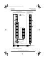
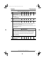
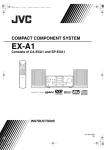
DIMENSIONS
c
=
G
=
=
b
H
=
Ø
a
Figure 1: Altivar 18 Dimensions
Table 5:
Dimensions
Catalog No.
a
b
c
ATV18U09M2
ATV18U18M2
4.41
(112)
7.17
(182)
ATV18U29M2
ATV18U18N4
ATV18U29N4
5.87
(149)
7.24
(184)
Mounting
Ø
Weight
6.7
(170)
0.20 (5)
3.3 (1.5)
3.3 (1.5)
6.77
(172)
0.20 (5)
4.6 (2.1)
4.4 (2.0)
4.6 (2.1)
G
H
4.76
(121)
3.94
(100)
6.18
(157)
5.39
(137)
ATV18U41M2
ATV18U54M2
ATV18U72M2
ATV18U41N4
ATV18U54N4
ATV18U72N4
7.28
(185)
8.46
(215)
6.22
(158)
6.73
(171)
7.95
(202)
0.24 (6)
6.2 (2.8)
7.3 (3.3)
7.3 (3.3)
6.8 (3.1)
7.3 (3.3)
7.3 (3.3)
ATV18U90M2
ATV18D12M2
ATV18U90N4
ATV18D12N4
8.27
(210)
11.81
(300)
6.69
(170)
7.48
(190)
11.02
(280)
0.28 (7)
17.2 (7.8)
17.2 (7.8)
17.6 (8.0)
17.6 (8.0)
ATV18D16N4
ATV18D23N4
9.65
(245)
15.35
(390)
7.48
(190)
8.86
(225)
14.57
(370)
0.40 (10)
26.4 (12.0)
26.4 (12.0)
Dimensions are in inches (millimeters).
Weights are in pounds (kilograms).
ATV18 FAN FLOW RATES
Table 6:
ATV18 Fan Flow Rates
Drive Controller
Fan Flow Rate
ATV18 U09M2, U18M2, U18N4
Non-ventilated
ATV18 U29M2, U29N4
8.8 CFM
0.25 m3/minute
ATV18 U41M2, U54M2, U72M2, U41N4, U54N4, U72N4
26.5 CFM
0.75 m3/minute
ATV18 U90M2, D12M2, U90N4, D12N4, D16N4, D23N4
45.9 CFM
1.3 m3/minute
© 1997–2000 Schneider Electric All Rights Reserved
5
52012-008-01 doc Page 6 Monday, November 20, 2000 5:28 PM
ALTIVAR 18 Drive Controller
Installation Precautions
52012-008-01B
November 2000
INSTALLATION PRECAUTIONS
• The ATV18 drive controller is a NEMA Open device and must be installed
in a suitable environment. The environment around the drive controller
must not exceed pollution degree 2 requirements as defined in NEMA
ICS-1 or IEC 664.
• When shipped the ATV18 has a protection rating of IP31 and can be
operated in an ambient of up to 40 °C. When installing the drive controller
in an enclosure with an ambient of up to 50 °C, remove the grey tape from
the top of the drive controller. With the grey tape removed, the drive
controller has a protection rating of IP20.
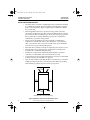
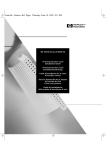
• Figure 2 shows the minimum clearances required around the drive
controller for unobstructed airflow; above and below: ≥ 4 in (100 mm),
sides: ≥ 2 in (50 mm). These clearances should not be used as minimum
enclosure size for proper thermal dissipation.
• Mount the drive controller vertically. Avoid placing near any heat sources.
• Verify that the voltage and frequency characteristics of the input line
match the drive controller nameplate rating.
• Installation of a disconnect switch between the input line and drive
controller is recommended. Follow national and local codes.
• Overcurrent protection is required. Install line power fuses recommended
in Table 10 on page 23 and Table 11 on page 23.
• Turn off all power before installing the drive controller. Place a “DO NOT
TURN ON” label on the drive controller disconnect. Before proceeding
with installation, lock the disconnect in the open position.
≥4
(100)
≥2
(50)
≥2
(50)
≥4
(100)
Dimensions are in inches (millimeters).
Figure 2: Minimum Clearances and Ventilation Flow
6
© 1997–2000 Schneider Electric All Rights Reserved
52012-008-01 doc Page 7 Monday, November 20, 2000 5:28 PM
52012-008-01B
November 2000
ALTIVAR 18 Drive Controller
Mounting in Type 12 (IP54) Metal Enclosure
MOUNTING IN TYPE 12 (IP54) METAL ENCLOSURE
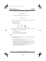
Calculating Enclosure Size
Below is the equation for calculating Rth (°C/W), the maximum allowable
thermal resistance of the enclosure:
T i = Max. internal ambient temp. (°C) around drive controller
Ti – To
R th = ----------------P
T o = Max. external ambient temp. (°C) around enclosure
P = Total power dissipated in enclosure (W)
For the power dissipated by the drive controllers at rated load, see Tables 1
and 2 on page 2 and Table 3 on page 3.
Useful heat exchange surface area, S (in2), of a wall-mounted enclosure
generally consists of the sides, top, and front. The minimum surface area
required for a drive controller enclosure is calculated as follows:
K
S = ---------R th
Rth = Thermal resistance of the enclosure (calculated previously)
K = Thermal resistance per square inch of the enclosure
K = 186 with enclosure fan
K = 233 without enclosure fan
Consider the following points when sizing the enclosure:
• Use only metallic enclosures, since they have good thermal conduction.
• This procedure does not consider radiant or convected heat load from
external sources. Do not install enclosures where external heat sources
(such as direct sunlight) can add to enclosure heat load.
• If additional devices are present inside the enclosure, consider the heat
load of the devices in the calculation.
• The actual useful area for convection cooling of the enclosure will vary
depending upon the method of mounting. The method of mounting must
allow for free air movement over all surfaces considered for convection
cooling.
The following sample illustrates calculation of the enclosure size for an
ATV18U72N4 (5 hp) drive controller mounted in a Type 12 enclosure.
•
•
•
•
Maximum external temperature: To = 25 °C
Power dissipated inside enclosure: P = 94 W
Maximum internal temperature: Ti = 40 °C
Thermal resistance per square inch of enclosure: K = 186
© 1997–2000 Schneider Electric All Rights Reserved
7
52012-008-01 doc Page 8 Monday, November 20, 2000 5:28 PM
ALTIVAR 18 Drive Controller
Mounting in Type 12 (IP54) Metal Enclosure
52012-008-01B
November 2000
• Calculate maximum allowable thermal resistance, Rth:
40 °C – 25 °C
Rth = ------------------------------------ = 0.16 °C/W
94 W
• Calculate minimum useful heat exchange surface area, S:
186
2
S = ----------- = 1162.5 in
0.16
Useful heat exchange surface area (S) of the proposed wall-mounted enclosure:
• Height: 24 in (610 mm)
• Width: 20 in (508 mm)
• Depth: 12 in (305 mm)
front area
top area
side area
S = ( 24 × 20 ) + ( 20 × 12 ) + 2 ( 24 × 12 ) = 1296 in
2
If the selected enclosure does not provide the required surface area or does not
meet application needs, consider the following:
• Use a larger enclosure.
• Add a passive heat exchanger to the enclosure.
• Add an air conditioning unit to the enclosure.
Ventilation
When mounting the drive controller inside a Type 12 or IP54 enclosure, follow
these ventilation precautions:
• Observe minimum clearance distances shown in Figure 2 on page 6.
• Follow the installation precautions on page 6.
• A stirring fan with filter may be necessary to circulate the air inside the
enclosure, prevent hot spots in the drive controller, and to distribute the
heat uniformly to surfaces used for convection cooling.
• If there is a possibility of condensation, keep the control supply switched
on during periods when the motor is not running or install
thermostatically-controlled strip heaters.
8
© 1997–2000 Schneider Electric All Rights Reserved
52012-008-01 doc Page 9 Monday, November 20, 2000 5:28 PM
52012-008-01B
November 2000
ALTIVAR 18 Drive Controller
Electromagnetic Compatibility (EMC)
ELECTROMAGNETIC COMPATIBILITY (EMC)
NOTE: This section focuses on applications requiring compliance to the European
Community EMC directive. The Altivar 18 is considered to be a component. It is neither
a machine nor a piece of equipment ready for use in accordance with the European
Community directives (machinery directive or electromagnetic compatibility directive).
It is the user’s responsibility to ensure that the machine meets these standards.
Installation Precautions for Meeting EN55011 Class A
General Rules
Ensure that the grounds of the drive controller, the motor, and the cable shields
are at equal potential.
Use shielded cables with the shields tied to ground at both ends of the motor
cable and the control cables. The ground connection to the shield must make
contact with the complete circumference of the shield. As long as there is no
discontinuity, this shielding can be achieved by using metallic conduit. Bonding
at conduit fittings is required.
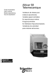
Installation Plan
1
2
ATV 18
5
3
4
6
7
Figure 3: Installation Diagram
Description of parts in Figure 3:
1. A sheet metal plate, which is not painted, and has an anti-corrosion
conductive treatment (ground plane). Painted sheet metal can be used on
the condition that a good electrical contact is made between the support
and fixation surfaces and 2 and 5.
© 1997–2000 Schneider Electric All Rights Reserved
9
52012-008-01 doc Page 10 Monday, November 20, 2000 5:28 PM
ALTIVAR 18 Drive Controller
Electromagnetic Compatibility (EMC)
52012-008-01B
November 2000
Description of parts in Figure 3 (continued):
2. The ATV18 is mounted directly to the metal plate. Ensure that all four
corner mounting points have good electrical contact with the metal plate.
3. Non-shielded input wire or cable, connected to the input inductors, if
used. Maintain separation between input wiring and motor wiring as
described in “General Wiring Practices” on page 12.
4. Non-shielded wire for the output of the fault relay contacts. Maintain
separation between fault relay wiring and motor wiring as described in
“General Wiring Practices” on page 12.
5. Fastening and grounding of the shields of cables 6 and 7 must be made as
close to the drive controller as possible.
— Strip the shields
— Use straps with appropriate dimensions on the stripped portions of the
shield for fastening to the sheet metal.
— Clamps should be stainless steel.
The shields must be well clamped to the sheet metal in order to have good
contact.
6. Shielded cable for connection to motor, with shield tied to ground at both
ends. At the drive controller, the shield is connected to the E or G/E
terminal on the far right of the power terminal strip. This shield must not
be interrupted. If intermediate terminal blocks are used, they must be in
EMC-shielded metallic boxes. The cable shield must have an ampacity
greater than or equal to that of the ground conductor.
7. Shielded cable for connection to control/command. For applications
requiring several conductors, a small wire size must be used (20 AWG or
0.5 mm2). The shield must be tied to ground at both ends. At the drive
controller, the shield is connected to the E or G/E terminal on the far right
of the power terminal strip. This shield must not be interrupted. If
intermediate terminal blocks are used, they must be in EMC-shielded
metallic boxes. Maintain separation between control/command wiring
and motor wiring.
NOTE: Connection at equal potential of the grounds between the drive controller,
motor, and cable shields does not preclude the connection of equipment ground
conductors as required by national and local codes.
10
© 1997–2000 Schneider Electric All Rights Reserved
52012-008-01 doc Page 11 Monday, November 20, 2000 5:28 PM
52012-008-01B
November 2000
ALTIVAR 18 Drive Controller
Wiring
WIRING
To access the terminal blocks remove the two screws and remove the cover.
When accessing the terminals, first perform the Bus Voltage Measurement
Procedure on page 39. Figure 4 shows the location of the cover screws.
DATA
ENT
Removable Cover
Screws
Figure 4: Accessing Terminal Strips
Figure 5 shows the location of the drive controller wiring terminals.
DATA
ENT
Control
Terminals
Equipment
Ground Terminal
Power
Terminals
Figure 5: Wiring Terminals
© 1997–2000 Schneider Electric All Rights Reserved
11
52012-008-01 doc Page 12 Monday, November 20, 2000 5:28 PM
ALTIVAR 18 Drive Controller
Wiring
52012-008-01B
November 2000
General Wiring Practices
Good wiring practice requires the separation of control circuit wiring from all
power (line) wiring. Power wiring to the motor must have the maximum
possible separation from all other power wiring, whether from the same drive
controller or other drive controllers; do not run in the same conduit. This
separation reduces the possibility of coupling electrical transients from power
circuits into control circuits or from motor power wiring into other power
circuits.
CAUTION
EQUIPMENT DAMAGE HAZARD
Follow wiring practices described in this document in addition to those already
required by the National Electrical Code and local electrical codes.
Failure to follow these instructions can result in injury or equipment damage.
Follow the practices below when wiring ALTIVAR 18 drive controllers:
• Use metallic conduit for all drive controller wiring. Do not run control and
power wiring in the same conduit.
• Separate metallic conduits carrying power wiring or low-level control
wiring by at least 3 in (7.62 cm).
• Separate non-metallic conduits or cable trays used to carry power wiring
from metallic conduit carrying low-level control wiring by at least 12 in
(30.5 cm).
• Whenever power and control wiring cross, the metallic conduits and nonmetallic conduits or trays must cross at right angles.
Branch Circuit Connections
All branch circuit components and equipment (such as transformers, feeder
cables, disconnect devices, and protective devices) must be rated for the
maximum input current of the ALTIVAR 18 drive controller, not the motor full
load current. The drive controller input current is stamped on the nameplate.
WARNING
OVERCURRENT PROTECTIVE DEVICES MUST BE PROPERLY COORDINATED
• To achieve published fault withstand current ratings, install the specified fuses
listed on the drive controller nameplate and in Table 10 and Table 11 on page 23.
• Do not connect the drive controller to the power feeder whose short circuit capacity
exceeds the drive controller withstand fault rating listed on the drive controller
nameplate.
Failure to follow these instructions can result in death, serious injury, or
equipment damage.
12
© 1997–2000 Schneider Electric All Rights Reserved
52012-008-01 doc Page 13 Monday, November 20, 2000 5:28 PM
52012-008-01B
November 2000
ALTIVAR 18 Drive Controller
Wiring
Output Wiring Precautions
WARNING
DRIVE CONTROLLER DAMAGE
The drive controller will be damaged if input line voltage is applied to output terminals
(U, V, W). Check the power connections before energizing the drive controller.
Failure to follow these instructions can result in death, serious injury, or
equipment damage.
The drive controller is sensitive to the amount of capacitance (either phase-tophase or phase-to-ground) present on the output power conductors. If
excessive capacitance is present, the drive controller may trip on overcurrent.
Follow the guidelines below when selecting output cable:
• Cable type: the cable selected must have a low capacitance phase-to-phase
and to ground. Do not use mineral-impregnated cable because it has a very
high capacitance. Immersion of cables in water increases capacitance.
• Cable length: the longer the cable, the greater the capacitance. Cable
lengths greater than 100 ft (30.5 m) may cause problems.
• Proximity to other output cables: because of the high frequency switching
and increased capacitance, the drive controller may fault under some
conditions.
• Do not use lightning arrestors on the output of the drive controller.
Wiring needs minimum inductance to protect the drive controller output from
short circuits. Provide at least 19.7 in (50 cm) of cable at the drive controller
output (U, V, W).
CAUTION
DRIVE CONTROLLER SWITCH FAILURE
For proper drive controller electronic short circuit protection, certain values of
inductance may be required in the output power wiring. Inductance can be supplied
by the power wiring or auxiliary inductors.
Failure to follow these instructions can result in equipment damage.
© 1997–2000 Schneider Electric All Rights Reserved
13
52012-008-01 doc Page 14 Monday, November 20, 2000 5:28 PM
ALTIVAR 18 Drive Controller
Wiring
52012-008-01B
November 2000
Grounding
For safe, dependable operation, ground the drive controller according to
National Electrical Code and all local codes. To ground the drive controller:
• Connect a copper wire from the equipment ground terminal to the power
system ground conductor. Wire size is determined by the drive controller
size and by national and local codes.
• Verify that resistance to ground is one ohm or less. Improper grounding
causes intermittent and unreliable operation.
DANGER
HAZARDOUS VOLTAGE
• Ground equipment using the connection provided as shown in Table 7 on page 15.
The drive controller panel must be properly grounded before applying power.
• Do not use metallic conduits as a ground conductor.
Failure to follow these instructions will result in death or serious injury.
Ground multiple drive controllers as shown in Figure 6. Do not loop or series
the ground cables.
YES
Drive Controller
Drive Controller
Drive Controller
Drive Controller
Drive Controller
Drive Controller
Drive Controller
Drive Controller
Drive Controller
Figure 6:
14
NO
Grounding Multiple Drive Controllers
© 1997–2000 Schneider Electric All Rights Reserved
52012-008-01 doc Page 15 Monday, November 20, 2000 5:28 PM
52012-008-01B
November 2000
ALTIVAR 18 Drive Controller
Wiring
Power Terminals
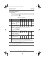
Table 7:
Power Terminal Strip Characteristics
Terminal
Function
L1
L2
Input power
ATV18
All models
L3
Three-phase units only
E or G/E Equipment ground connection
All models
PO
Not used. Do not disconnect link
between PO and PA.
All models
PA
PB
Connection for dynamic braking
resistance
All models
PC
Not used
D16N4U and D23N4 only
U
V
W
Output connections to motor
All models
E or G/E
Shield or equipment ground connection All models
Located on heatsink on ATV18U09M2 and
U18M2. Located on metal cable entry plate
on other models.
Equipment ground connection
L1 L2
E PO PA PB U
ATV18U09M2 to U41M2
V
W
E
E PO PA PB U
V
W
L1 L2 L3 G/E PO PA PB U
V
W G/E
L1 L2 L3
E
ATV18U54M2, U72M2, and
ATV18U18N4 to U72N4
ATV18U90M2, D12M2,
U90N4, D12N4
PA PB PC
PO L1 L2 L3 G/E U
Figure 7:
V
W G/E
ATV18D16N4 and D23N4
Location of Power Terminals
© 1997–2000 Schneider Electric All Rights Reserved
15
52012-008-01 doc Page 16 Monday, November 20, 2000 5:28 PM
ALTIVAR 18 Drive Controller
Wiring
Table 8:
52012-008-01B
November 2000
Power Terminal Wire Size and Torque
Maximum Wire Size [1]
AWG (mm2)
Torque
lb-in (N•m)
14 (1.5)
9 (1.0)
10 (4)
11 (1.2)
U90M2, D12M2, U90N4, D12N4
8 (6)
21 (2.4)
D16N4, D23N4
6 (10)
35 (4)
ATV18
U09M2, U18M2
U29M2, U41M2, U54M2, U72M2, U18N4,
U29N4, U41N4, U54N4, U72N4
[1] 75
°C copper.
Equipment Ground Terminal
Equipment ground terminals are located on the power terminal strip as shown
in Table 7 on page 15. In addition, an M5 equipment ground screw terminal is
located on the heatsink of the ATV18U09M2 and U18M2 and on the metal cable
entry plate on all other units. Maximum wire size for this screw terminal is
8 AWG (6 mm2). Tightening torque is 21 lb-in (2.4 N•m) for drive controllers
ATV18U09M2 and U18M2. Tightening torque is 31 lb-in (3.45 N•m) for all other
units.
16
© 1997–2000 Schneider Electric All Rights Reserved
52012-008-01 doc Page 17 Monday, November 20, 2000 5:28 PM
52012-008-01B
November 2000
ALTIVAR 18 Drive Controller
Wiring
Control Terminals
Maximum wire size for all control terminals is 16 AWG (1.5 mm2). Tightening
torque is 4.4 lb-in (0.5 N•m). The control terminals are galvanically isolated
from the power section.
Table 9:
Control Terminal Strip Characteristics
Terminal
Reference
ATV18•••••
Function
Characteristics
SA
SB
SC
Fault relay
Minimum: 10 mA, 24 Vdc
N.O./N.C. contact
Maximum: inductive load of
Closed when drive controller energized, with
0.3 A, 250 Vac
no fault
1.5 A, 30 Vdc
+10
Internal supply for reference potentiometer
10 Vdc, +15%, -0%
10 mA maximum
Manual speed potentiometer value: 1 kΩ to 10 kΩ
AI1
Analog input 1: Speed reference voltage
input
0 to +10 Vdc, Impedance = 30 kΩ
AI2
or
AIC [1]
Analog input 2: Voltage reference
or
Current analog input: current reference
0 to +10 Vdc, Impedance = 30.55 kΩ
or
0-20 mA, 4-20 mA, Impedance = 400 Ω
COM
Common for logic inputs, analog input, and
logic output
0V
LI1
LI2
LI3
LI4
Logic input 1
Logic input 2
Logic input 3
Logic input 4
24 Vdc; State 0: V<5 V; State 1: V>11 V;
Vmax = 30 V
+24
Internal supply for logic inputs and outputs
24 Vdc, 100 mA maximum
LO+
Supply for logic output, to be connected to
+24 or to external 24 V supply
Maximum 30 Vdc
LO
Open collector PLC-compatible logic output
+24 Vdc, maximum 20 mA with internal supply or
200 mA with external supply
[1]
AI2 or AIC can be summed with AI1. Both inputs are reassignable. Do not use them at the same time.
SA
SC
Figure 8:
SB
+10
AI1
AI2
AIC COM LI1
LI2
LI3
LI4
+24
LO+
LO
Location of Control Terminals
© 1997–2000 Schneider Electric All Rights Reserved
17
52012-008-01 doc Page 18 Monday, November 20, 2000 5:28 PM
ALTIVAR 18 Drive Controller
Using the Logic Inputs
52012-008-01B
November 2000
USING THE LOGIC INPUTS
The logic inputs may be operated from either the internal supply or an external
supply. The possible assignments of LI1 to LI4 are shown below.
LI1: Forward. Cannot be reassigned.
LI1
When the contact is closed, the reference frequency will be
applied to the motor in the forward direction.
+24
LI2, LI3, and LI4 can be assigned to the following functions:
• Reverse: FSt
LI2 or
LI3 or
LI4
When the contact is closed, the reference frequency will be
applied to the motor in the reverse direction. If LI1 and LI2
are closed at the same time, forward direction has priority.
Otherwise, the direction selected first has priority.
+24
• 2 Preset Speeds: PS2
LI2 or
LI3 or
LI4
When the contact is open, the reference = LSP + analog
reference. When the contact is closed, the reference = HSP.
+24
• 4 Preset Speeds: PS4
K2
K1
LI2 or
LI3 or
LI4
(PS4)
LI2 or
LI3 or
LI4
(PS2)
+24
If K1 and K2 are open, the reference is LSP + analog reference.
If K1 is closed and K2 is open, the reference is SP3 (Speed 3).
If K1 is open and K2 is closed, the reference is SP4 (Speed 4).
If K1 and K2 are closed, the reference is HSP.
• Jog: JOG
LI2 or
LI3 or
LI4
18
+24
If the contact is closed and then the direction contact is
closed, the ramp time is 0.1 s regardless of the settings of
ACC and dEC. If the drive is already running and the
contact assigned to JOG is closed, the ramp times will
be equal to ACC and dEC. The minimum time between two
jog operations is 0.5 s.
© 1997–2000 Schneider Electric All Rights Reserved
52012-008-01 doc Page 19 Monday, November 20, 2000 5:28 PM
52012-008-01B
November 2000
ALTIVAR 18 Drive Controller
Using the Logic Inputs
Jog command
Run direction
Speed reference
JOG
JOG
JOG
Frequency
Figure 9:
Jog Timing Diagram
NOTE: Whenever the drive controller is running in Jog, automatic DC injection
braking upon stop is inhibited. However, DC injection braking by logic input has
priority over Jog run.
• Fast Stop: FSt
LI2 or
LI3 or
LI4
+24
Fast stop is commanded when the contact between the logic
input assigned to this function and +24 is opened.
The ramp time is the dEC time divided by 4, but limited to the minimum
acceptable time for braking without causing an overbraking fault. The ramp is
automatically adapted if the braking capacity is exceeded.
NOTE: When in fast stop, automatic DC injection braking and DC injection by logic
input are inhibited.
• DC Injection Braking: dCI
LI2 or
LI3 or
LI4
+24
DC injection braking is commanded when the contact between
the logic input assigned to this function and +24 is closed.
The current injected is equal to the drive controller nominal current for 5
seconds. After 5 seconds, the current is limited to a maximum value of 0.5 times
the motor thermal current (ItH).
NOTE: Automatic DC injection braking remains active even if a logic input is assigned
to dCI.Fast stop has priority over DC injection braking.
© 1997–2000 Schneider Electric All Rights Reserved
19
52012-008-01 doc Page 20 Monday, November 20, 2000 5:28 PM
ALTIVAR 18 Drive Controller
Using the Analog Inputs
52012-008-01B
November 2000
USING THE ANALOG INPUTS
AI1 is a 0 to +10 V analog input which is used for speed reference. In addition,
one of two other analog inputs may be used, either:
• AI2: 0 to +10 V or +2 to +10 V voltage input, or
• AIC: 0 to 20 mA (factory setting) or 4 to 20 mA current input.
AI2 or AIC can be assigned to reference summing with AI1 or PI feedback.
• Reference summing with AI1: SAI
AI1
(0 to +10V)
+
+
AI2
(0 to +10V)
or
AIC
(0 to 20 mA or
4 to 20 mA)
Figure 10: Reference Summing
• PI Feedback: PIF
This assignment automatically configures AI1 as PI setpoint input. AI2 or AIC
is the PI feedback input.
P
AI1
0 to +10 V
x Fb5
AI2
(0,1…100)
0 to +10 V
or
AIC
0 to 20 mA or 4 to 20 mA
rPG
0.01 to 100
I
rIG
0.01 to 100 x 1/s
Figure 11: PI Feedback
To set up the PI regulator, with the system in open loop configuration (sensor
not connected), adjust High Speed setting (HSP) so that maximum flow or
pressure is obtained. Then connect the sensor.
The values of proportional gain (rPG) and integral gain (rIG) are factory
set to give adequate performance for most applications. Factory setting for both
parameters is 1.00, meaning that the output is modified by 1.00 times the input
error for the proportional component and 1.00 times the input error for one
second for the integral component. If improved dynamic performance is
required, these parameters can be adjusted over the range of 1.00 to 100, or if
the system is unstable, from 0.01 to 0.99.
20
© 1997–2000 Schneider Electric All Rights Reserved
52012-008-01 doc Page 21 Monday, November 20, 2000 5:28 PM
52012-008-01B
November 2000
ALTIVAR 18 Drive Controller
Function Compatibility
Page 32 further explains the adjustment parameters rPG (Proportional Gain),
rIG (Integral Gain) and FbS (Feedback Scaling).
NOTE: The PI Feedback function is not compatible with Preset Speeds or Jog.
FUNCTION COMPATIBILITY
➞
Jog
➞
➞➞
➞
➞
➞
➞
➞
➞➞
Preset speeds
Fast stop
➞ ➞➞
➞
➞
DC injection braking
by logic input
Reverse direction
Forward direction
PI feedback
Summing input
➞
Fast stop
Jog
Preset speeds
➞
➞
DC injection braking
by logic input
➞
Summing input
PI feedback
Forward direction
Reverse direction
➞
Automatic DC injection
braking
➞
Automatic DC injection
braking
The number of inputs/outputs required by a function, the number of inputs/
outputs on the drive controller available for reassignment, and the
compatibility of the selected functions (see Figure 12) limit the number of
functions which can be assigned. There are 3 assignable logic inputs on the
drive controller. The following functions require one input: reverse, DC
injection braking, fast stop, jog, and 2 preset speeds. The use of 4 preset speeds
requires two inputs.
Function priority
➞➞
➞
➞
Non-compatible functions
Compatible functions
No significance
The function indicated by the arrow
has priority over the other one.
The first operated has priority.
Figure 12: Function Compatibility Chart
© 1997–2000 Schneider Electric All Rights Reserved
21
52012-008-01 doc Page 22 Monday, November 20, 2000 5:28 PM
ALTIVAR 18 Drive Controller
Wiring Diagram
52012-008-01B
November 2000
WIRING DIAGRAM
1-Phase Power Supply (1)
3-Phase Power Supply
FU3
LI4
+24
LO+
LI3
LI2
LI1
KA
(4)
+24 V
or
0 to +10 V
COM
0-20 mA
or
4-20 mA
0V
LO+
+24
AI2
LO
LI4
AIC
LI2
COM
Manual
Speed
Pot.
LI3
LI1
AI1
SA
Brake
Resistor
if required
+10
SB
L3
W
SC
L2
V
M
3ø
AC
PO
PA
PB
L1
FU2
(5)
(3)
U
FU1
(2)
24 V External Supply
(1) ATV18U09M2 to U41M2 only.
(2) Line inductor if required (1-phase or 3-phase).
(3) Fault relay contacts for remote signalling of the drive controller state. Contact state shown with
drive controller deenergized or faulted.
(4) Relay must draw ≤ 20 mA to be used on internal supply. For relay up to 200 mA, use external
supply.
(5) This jumper is needed only if logic output is used. When using a +24 V external supply, connect
the 0 V to the COM terminal, and connect LO+ to the external +24 V instead of the +24 V
terminal on the drive controller.
Figure 13: ALTIVAR 18 Drive Controller Wiring Diagram
FAULT RELAY
The fault relay is energized whenever there is power to the drive controller and
there is no fault. It is a Normally Open-Normally Closed contact.
After a fault, the drive controller is reset either by cycling power, allowing the
red LED (see Figure 15 on page 27) to go dark; or automatically after certain
faults if automatic restart is selected. For further explanation of automatic
restart, refer to page 37.
22
© 1997–2000 Schneider Electric All Rights Reserved
52012-008-01 doc Page 23 Monday, November 20, 2000 5:28 PM
52012-008-01B
November 2000
ALTIVAR 18 Drive Controller
Recommended Fuses
RECOMMENDED FUSES
Table 10:
Recommended Fuses for 230 V Drive Controllers
Motor
[1]
Drive Controller
Class J [1]
HP
ATV18•••••
Class CC
0.37
0.5
U09M2
600 V, 6 A
600 V, 6 A
0.75
1
U18M2
600 V, 10 A
600 V, 10 A
1.5
2
U29M2
600 V, 20 A
600 V, 20 A
2.2
3
U41M2
600 V, 25 A
600 V, 25 A
3
--
U54M2
600 V, 25 A
600 V, 25 A
4
5
U72M2
—
600 V, 30 A
5.5
7.5
U90M2
—
600 V, 40 A
7.5
10
D12M2
—
600 V, 40 A
Fast-acting or time-delay Class J fuses are acceptable.
Table 11:
Recommended Fuses for 460 V Drive Controllers
Motor
[1]
Fuses
kW
Drive Controller
Fuses
Class CC
Class J [1]
kW
HP
ATV18•••••
0.75
1
U18N4
600 V, 5 A
600 V, 5 A
1.5
2
U29N4
600 V, 10 A
600 V, 10 A
2.2
3
U41N4
600 V, 10 A
600 V, 10 A
3
--
U54N4
600 V, 15 A
600 V, 15 A
4
5
U72N4
600 V, 20 A
600 V, 20 A
5.5
7.5
U90N4
600 V, 25 A
600 V, 25 A
7.5
10
D12N4
—
600 V, 40 A
11
15
D16N4
—
600 V, 40 A
15
20
D23N4
—
600 V, 60 A
Fast-acting or time-delay Class J fuses are acceptable.
Equip all inductive circuits near the drive controller (relays, contactors,
solenoid valves) with noise suppressors or connect them to a separate circuit.
When commanding the power by line contactor, avoid frequently opening and
closing the line contactor which could cause premature failure of the filtering
capacitors and precharge resistor. Use inputs LI1 to LI4 to command the drive
controller. Limit operations of the line contactor to less than once per minute.
© 1997–2000 Schneider Electric All Rights Reserved
23
52012-008-01 doc Page 24 Monday, November 20, 2000 5:28 PM
ALTIVAR 18 Drive Controller
Thermal Overload Protection
52012-008-01B
November 2000
THERMAL OVERLOAD PROTECTION
• Thermal overload protection of the drive controller is accomplished by a
thermal sensor on the heatsink of the drive controller and a calculation of
the I2t.
• In addition, the ALTIVAR 18 drive controller provides indirect motor
thermal protection by continuously calculating the I2t of the motor based
on the setting of the ItH parameter.
These methods allow thermal protection of the motor and drive controller for
normal conditions of ambient temperature.
Typical trip values are:
• motor current = 185% of nominal drive controller current for 2 seconds
• motor current = 150% of nominal drive controller current for 60 seconds
If the motor current ≤ 110% of the nominal drive controller current, the drive
controller will not trip.
Derating for switching frequencies > 4 kHz are automatically taken into
account and the allowable I2t is reduced.
The thermal state of the drive controller is automatically reset when power is
removed.
CAUTION
LOSS OF MOTOR OVERLOAD PROTECTION
• Setting the ItH parameter to maximum will disable the internal motor overload
protection function.
• In this case, external motor overload protection must be provided.
When using external overload relays connected to the drive controller output, the
overload relay must be capable of operation over the expected range of drive
controller output frequencies (including direct current).
When DC injection braking is used:
• The overload relay must be suitable for operation with direct current flowing
in the motor.
• Do not use overload relays equipped with current transformers for sensing
the motor current.
Failure to follow these instructions can result in equipment damage.
24
© 1997–2000 Schneider Electric All Rights Reserved
52012-008-01 doc Page 25 Monday, November 20, 2000 5:28 PM
52012-008-01B
November 2000
ALTIVAR 18 Drive Controller
Available Torque
CAUTION
MOTOR OVERHEATING
This drive controller does not provide direct thermal protection for the motor. Use of a
thermal sensor in the motor may be required for protection at all speeds and loading
conditions. Consult the motor manufacturer for thermal capability of the motor when
operated over the desired speed range.
Failure to follow this instruction can result in injury or equipment damage.
AVAILABLE TORQUE
Continuous duty:
• For self-ventilated motors, motor cooling depends on the speed.
• Continuous duty results in derating for speeds less than 50% of the
nameplate motor speed.
Operation in overspeed:
• In overspeed operation, the voltage no longer increases with the
frequency, resulting in reduced induction in the motor which translates
into loss of torque. Consult the motor manufacturer to ensure that the
motor can operate in overspeed.
• For a special motor, the nominal frequency and the maximum frequency
can be adjusted between 40 and 320 Hz.
CAUTION
MACHINERY OVERSPEED
Some motors and/or loads may not be suited for operation above the nameplate
motor speed and frequency. Consult the motor manufacturer before operating the
motor abovethe rated speed.
Failure to follow this instruction can result in injury or equipment damage.
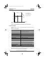
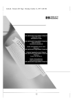
Figure 14 on page 26 shows the typical torque characteristics of the ALTIVAR 18
drive controller.
© 1997–2000 Schneider Electric All Rights Reserved
25
52012-008-01 doc Page 26 Monday, November 20, 2000 5:28 PM
ALTIVAR 18 Drive Controller
Available Torque
52012-008-01B
November 2000
T/Tn
1.5
3
1 Self-ventilated motor
1.2
2 Force-ventilated motor
1
0.95
3 Transient overtorque
2
1
0.5
N (Hz)
0
(50 Hz)
(60 Hz)
1 3
1 3
25
30
50
60
Figure 14: Typical ALTIVAR 18 Drive Controller Torque Characteristics
FACTORY SETTINGS
The ALTIVAR 18 is preset for constant torque applications. Table 12 lists factory
settings.
Table 12:
Factory Settings
Function
Setting
Display
Drive ready (when stopped)
Reference frequency (when running)
Base frequency
50 Hz
Motor voltage
230 V or 400 V, depending on the model
Acceleration and deceleration ramps
3s
Low speed
0 Hz
High speed
50 Hz
Frequency loop gain
Standard
Motor thermal current
Nominal drive controller current
DC braking current at stop
0.7 times nominal drive controller current for 0.5 s
Operation
Constant torque with sensorless vector control
Logic inputs
2 run directions (LI1, LI2)
4 preset speeds (LI3, LI4): 0 Hz, 5 Hz, 25 Hz, 50 Hz
Analog inputs
AI1: 0 to +10 V reference
AI2 (0 to +10V) or AIC (0 to 20 mA) summed with AI1
Logic output
LO: Speed reference attained
Deceleration ramp adaptation
Automatic in the case of overvoltage when braking
Switching frequency
4 kHz
To modify these adjustments, use the keypad to change the parameter settings.
The following section explains the keypad and parameters. For operation at
60 Hz, the bFr and HSP parameters must be adjusted.
26
© 1997–2000 Schneider Electric All Rights Reserved
52012-008-01 doc Page 27 Monday, November 20, 2000 5:28 PM
52012-008-01B
November 2000
ALTIVAR 18 Drive Controller
Using the Display Keypad
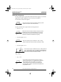
USING THE DISPLAY KEYPAD
Figure 15 shows the locations and functions of the display keypad keys.
Red LED
DC Bus
rdY
Go to the previous parameter
or increase the value displayed
DATA
Four 7-segment LED display
ENT
Save the parameter
or the value displayed
Go from parameter name to
parameter value and vice-versa
Go to the next parameter
or decrease the value displayed
Figure 15: Functions of Keys and Display
Normal display when there is no fault:
•
•
•
•
•
Init: Initialization sequence
rdY: Drive controller ready
43.0: Display of the reference frequency
dcb: Braking by DC injection in progress
rtrY: Automatic restart in progress
Figures 16, 17, and 18 illustrate operation of the keypad push buttons.
bFr
(1 flash)
ACC
DATA
“0
{8
ENT
ACC
dEC
{8
DATA
Etc.
Figure 16: Example 1: Adjustment of Ramp Time
© 1997–2000 Schneider Electric All Rights Reserved
27
52012-008-01 doc Page 28 Monday, November 20, 2000 5:28 PM
ALTIVAR 18 Drive Controller
Parameter Summary
52012-008-01B
November 2000
FLt
(1 flash)
L2A
DATA
no
YES
YES
ENT
L2A
UFt
DATA
Etc.
Figure 17: Example 2: Access to Level 2 Parameters
LI4
(1 flash)
LO
DATA
SrA
FtA
ENT
LO
FtA
DATA
AIC
Etc.
Figure 18: Example 3: Configuration of a Logic Output
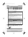
PARAMETER SUMMARY
Figure 19 lists the parameters. There are two levels of access:
• Level 1: adjustments (basic configuration)
• Level 2: extensions in functionality
There are three types of parameters:
• Display: values displayed by the drive controller
• Adjustment: can be modified when the motor is running or stopped
• Configuration: only modifiable when the motor is stopped. Can be
displayed when the motor is running.
28
© 1997–2000 Schneider Electric All Rights Reserved
52012-008-01 doc Page 29 Monday, November 20, 2000 5:28 PM
52012-008-01B
November 2000
ALTIVAR 18 Drive Controller
Parameter Summary
Level 1 Parameters
rdY
or
4{5
Level 2 Parameters
UFt
When
running motor
FrH
* tUn
LCr
UnS
rFr
FrS
ULn
tFr
bFr
brA
ACC
* SLP
dEC
tLS
LSP
LI2
HSP
SP3
LI3
*
SP4
*
JOG
*
* Fdt
* rPG
* rIG
* FbS
FLG
ItH
JPF
IdC
tdC
UFr
LI4
LO
AIC
CrL
SPr
SFr
StP
FLt
L2A
= no
L2A
Access to Level 2
Atr
YES
no
FCS
L2A = YES
CPU
L2A = YES
Display
Configuration: can only be modified
while motor is stopped
Adjustment: can be modified
while motor is running or stopped
* Parameter displayed only if the corresponding function is configured
Figure 19: Parameter Summary
© 1997–2000 Schneider Electric All Rights Reserved
29
52012-008-01 doc Page 30 Monday, November 20, 2000 5:28 PM
ALTIVAR 18 Drive Controller
Drive Controller Set Up
52012-008-01B
November 2000
DRIVE CONTROLLER SET UP
Level 1 Parameters
Table 13 shows the Level 1 parameters. The maximum value is always obtained
by pressing and holding the
key. The minimum value is always obtained by
pressing and holding the
key.
Table 13: Level 1 Parameters
Code
Factory
Setting
Function
rdY
Drive ready
FrH
LCr
rFr
ULn
Frequency reference
Motor current
Rotation frequency
Maintains voltage
bFr
Base frequency. Select the same
frequency as the mains frequency
Max.
Value
Min.
Value
Units
Min.
Increment
Type
Display
Choice of
parameter
displayed
while
running [1]
Hz
A
Hz
V
FrH
50
50
60
0.1
0.1
0.1
1
Hz
Display
Display
Display
Display
Config.
If the value of bFr is changed, the drive controller will display init as it automatically adjusts the
nominal motor voltage (UnS) and nominal frequency (FrS) to the following values:
ATV18...M2: bFr = 50: 230 V/50 Hz
bFr = 60: 230 V/60 Hz
ATV18...M4: bFr = 50: 400 V/50 Hz
bFr = 60: 460 V/60 Hz
The settings of UnS and FrS can be modified in the level 2 parameters.
ACC
dEC
Linear acceleration ramp
Linear deceleration ramp
3.0
3.0
3600
3600
0.1
0.1
s
s
0.1 (from 0.1
to 999.9) or
1 (from 1000
to 3600)
Adjust.
Adjust.
0.0
50.0
=HSP
=tFr [2]
0.0
=LSP
Hz
Hz
0.1
0.1
Adjust.
Adjust.
33
100
0
1
Adjust.
These ramps are defined for the base frequency.
For example, for a 10 s ramp:
if bFr = 50 Hz, 0 to 25 Hz takes 5 s
if bFr = 60 Hz, 0 to 30 Hz takes 5 s
LSP
HSP
Low speed
High speed: ensure that the
adjustment matches the motor and the
application
FLG
Frequency loop gain
Dependent on the inertia and resistive torque of the driven mechanical equipment:
—machines with high resistive torque or high inertia: progressively reduce FLG from 33 to 0.
—machines with fast cycles, low resistive torque and low inertia: gradually increase the gain from
33 to 100. An excess of gain can cause unstable operation.
30
[1]
LCr, rFr, and ULn cannot be saved by pressing ENT, but can be displayed momentarily, until the motor
is stopped, or the next parameter is displayed.
[2]
tFr is a level 2 parameter, adjustable from 40 to 320 Hz, preset at 60 Hz. For HSP > 60 Hz, first modify
tFr by going to the level 2 parameters.
© 1997–2000 Schneider Electric All Rights Reserved
52012-008-01 doc Page 31 Monday, November 20, 2000 5:28 PM
52012-008-01B
November 2000
ALTIVAR 18 Drive Controller
Drive Controller Set Up
Table 13: Level 1 Parameters (Continued)
Code
ItH
Factory
Setting
Function
Motor thermal protection
[3]
In
[4]
Max.
Value
Min.
Value
Units
Min.
Increment
Type
1.15 In
0.5 In
A
0.1
Adjust.
[4]
[4]
Adjust ItH to the motor nameplate current. The thermal state of the motor thermal protection is
automatically reset when power is removed. To suppress motor thermal protection, increase the value
of Ith to the maximum and provide external thermal protection.
CAUTION
LOSS OF MOTOR OVERLOAD PROTECTION
• Setting the ItH parameter to maximum will disable the internal motor overload
protection function.
• In this case, external motor overload protection must be provided.
When using external overload relays connected to the drive controller output, the
overload relay must be capable of operation over the expected range of drive
controller output frequencies (including direct current).
When DC injection braking is used:
• The overload relay must be suitable for operation with direct current flowing
in the motor.
• Do not use overload relays equipped with current transformers for sensing
the motor current.
Failure to follow these instructions can result in equipment damage.
CAUTION
MOTOR OVERHEATING
This drive controller does not provide direct thermal protection for the motor. Use of a
thermal sensor in the motor may be required for protection at all speeds and loading
conditions. Consult the motor manufacturer for the thermal capability of the motor
when operated over the desired speed range.
Failure to follow this instruction can result in injury or equipment damage.
JPF
Jump frequency with a bandwidth of
0.0
HSP
2 Hz. Suppression of a critical speed
which causes mechanical resonance. Factory setting of 0
indicates that the function is not used.
0.0
Hz
0.1
Adjust.
f
JPF
2 Hz
[3]
For motors in parallel fed by the same drive controller, a separate thermal relay should be added for
each motor.
[4]
In = drive controller rated output current. See Table 1 and Table 2 on page 2 and Table 3 on page 3.
© 1997–2000 Schneider Electric All Rights Reserved
31
52012-008-01 doc Page 32 Monday, November 20, 2000 5:28 PM
ALTIVAR 18 Drive Controller
Drive Controller Set Up
52012-008-01B
November 2000
Table 13: Level 1 Parameters (Continued)
Code
Idc
tdc
Function
Factory
Setting
Automatic DC injection current level
0.7 In
Automatic DC injection current time
0.5
[4]
Max.
Value
In
[4]
25.5
Min.
Value
Units
Min.
Increment
Type
0.25
ItH
A
0.1
Adjust.
0.0
s
0.1
Adjust.
Adjustment to 0 suppresses automatic DC injection. Adjustment to 25.5 causes permanent injection
of DC upon stop. [5]
WARNING
NO HOLDING TORQUE
• DC injection braking does not provide holding torque at zero speed.
• DC injection braking does not function during loss of power or drive controller fault.
• When required, use separate brake for holding torque.
Failure to follow these instructions can result in death, serious injury, or
equipment damage.
UFr
Allows optimization of torque at low
speed
20
100
0
1
Adjust.
SP3 [6] 3rd preset speed
5.0
HSP
LSP
SP4 [6] 4th preset speed
25.0
HSP
LSP
Hz
0.1
Adjust.
Hz
0.1
10
10
Adjust.
0
Hz
0.1
Adjust.
Frequency level associated with
“frequency level attained” when LO is
assigned to this function. This level
allows a hysteresis of 0.2 Hz.
0
HSP
LSP
Hz
0.1
Adjust.
rPG [6] Proportional gain for the PI feedback
function
1
100.0
0.01
0.01
Adjust
rIG [6] Integral gain for the PI feedback
function
1
100.0
0.01
0.01
Adjust.
FbS [6] Feedback scaling factor for the PI
feedback function, associated with the
analog input AIC or AI2.
1
100.0
0.1
0.1
Adjust.
JOG [6] Jog speed
Fdt
[6]
FLt
L2A
1/s
By pressing the DATA key when this
parameter is displayed, the last fault
can be displayed. When there has been no fault, the display is nErr.
Display
Level 2 access
Config.
no
YES
no
no: no → next display will be rdY if down arrow pressed
yes: YES → next display will be the first level 2 parameter if down arrow pressed
[4]
32
In = drive controller rated output current. See Table 1 and Table 2 on page 2 and Table 3 on page 3..
[5]
Note that during braking, configuration parameters cannot be modified. Adjust tdc to 25.5 s if
continuous DC injection is necessary.
[6]
These parameters only appear if the associated functions have been selected.
© 1997–2000 Schneider Electric All Rights Reserved
52012-008-01 doc Page 33 Monday, November 20, 2000 5:28 PM
52012-008-01B
November 2000
ALTIVAR 18 Drive Controller
Drive Controller Set Up
Level 2 Parameters
Level 2 parameters are accessed by setting the L2A parameter to yes. Table 14
lists the Level 2 parameters and their functions. The maximum value is always
obtained by pressing and holding the
key. The minimum value is always
obtained by pressing and holding the
key.
WARNING
UNINTENDED EQUIPMENT ACTION
• Application of voltages to the logic inputs while a Level 2 parameter is being
adjusted may result in power being applied to the motor.
• While changing a Level 2 parameter, ensure that no voltage is applied to the
logic inputs.
Failure to follow these instructions can result in death, serious injury, or
equipment damage.
© 1997–2000 Schneider Electric All Rights Reserved
33
52012-008-01 doc Page 34 Monday, November 20, 2000 5:28 PM
ALTIVAR 18 Drive Controller
Drive Controller Set Up
52012-008-01B
November 2000
Table 14: Level 2 Parameters
Code
UFt
tUn
UnS
FrS
tFr
Function
Factory
Setting
n
Max
Value
L
Min
Value
nLd
60.0
320.0
40.0
Units
Min
Increment
Type
Selection of the type of volts/
Config.
frequency ratio
L: constant torque for special motors or motors connected in parallel
P: variable torque
n: sensorless flux vector control for constant torque applications
nLd: energy savings, for variable torque applications
Auto-tune. Only active when UFt is
no
YES
no
Config.
set for n or nLd.
no: no auto-tune (factory parameters for standard IEC motors)
donE: auto-tune has already been performed (auto-tune parameters already in use)
YES: setting to YES and pressing ENT starts auto-tune
When auto-tune is completed, rdY is displayed. Returning to tUn displays donE. If tnF (tuning fault)
appears, the motor is not adapted to the drive controller. Use L or P mode.
Nominal motor voltage. Set to the
Config.
nameplate value.
Maximum, minimum, and factory preset values depend on the model and the setting of the bFr
parameter (level 1).
ATV18...M2
230
240
200
V
1
ATV18...N4 with bFr = 50
400
460
380
V
1
ATV18...N4 with bFr = 60
460
460
380
V
1
Nominal motor frequency
bFr
320.0
40.0
Hz
0.1
Config.
Set to the nameplate value if it is different from that set by bFr.
Maximum output frequency
Hz
0.1
Config.
CAUTION
MACHINERY OVERSPEED
Some motors and/or loads may not be suited for operation above the nameplate
motor speed and frequency. Consult the motor manufacturer before operating the
motor above the rated speed.
Failure to follow this instruction can result in injury or equipment damage.
brA
SLP
tLS
[1]
34
Automatic deceleration ramp
YES
no
YES
adaptation to avoid an overbraking
(ObF) fault.
YES: function active
no: function not active
This function may be incompatible with the use of dynamic braking.
[1]
5.0
0.0
Slip compensation
This parameter only appears if UFt is set for n.
Config.
Hz
0.1
Adjust.
Low speed run time. Time at which
0.0
25.5
0.0
s
0.1
Adjust.
the motor runs at LSP if reference
goes to 0 and direction
command (FW or RV) is still present. If tLS = 0, the drive controller will run at the LSP setting as long
as FW or RV is present. The drive controller restarts when the reference becomes greater than 0, or
if the direction input (FW or RV) is cycled.
The factory setting depends on the drive controller rating.
© 1997–2000 Schneider Electric All Rights Reserved
52012-008-01 doc Page 35 Monday, November 20, 2000 5:28 PM
52012-008-01B
November 2000
ALTIVAR 18 Drive Controller
Drive Controller Set Up
Table 14: Level 2 Parameters (Continued)
Code
LI2
Function
Factory
Setting
Max
Value
Min
Value
Units
Min
Increment
Type
Reassignment of the LI2 logic input
Note: Before assigning, make sure that there is no voltage to the logic input.
WARNING
UNINTENDED EQUIPMENT ACTION
• Assigning a logic input when it is in state 1 (high, with voltage present) can cause
the motor to start.
• Before assigning, verify that there is no voltage to the logic input.
Failure to follow these instructions can result in death, serious injury, or
equipment damage.
If the function is already assigned to another input, it will appear as a choice, but will not be saved upon
pressing ENT. If PS2 and PS4 are both assigned, the input assigned to PS4 must be changed before
the input assigned to PS2 can be changed.
rrS
OFF
PS4
Config.
If AIC is assigned for summing with
AI1 (SAI) [2], and one of the logic
inputs is assigned to PS2 [2], the
choices for LI2 are:
OFF: not assigned
rrS: reverse
dCI: continuous DC injection braking drive In for 5s, then at 0.5 ItH
WARNING
NO HOLDING TORQUE
• DC injection braking does not provide holding torque at zero speed.
• DC injection braking does not function during loss of power or drive controller fault.
• When required, use separate brake for holding torque.
Failure to follow these instructions can result in death, serious injury, or
equipment damage.
FSt: Fast stop. This function is active when the LI is at state 0 (off)
JOG: Jog [3]
PS2: 2 preset speeds [3] (however, display will not flash when ENT is pressed because another input
was already assigned to PS2)
PS4: 4 preset speeds [3]
If AIC is assigned for summing with
rrS
OFF
PS2
Config.
AI1 (SAI), and no other LI is assigned
to PS2, the choices for LI2 are:
OFF: not assigned
rrS: reverse
dCI: continuous DC injection braking at drive In for 5s, then at 0.5 ItH
FSt: Fast stop. This function is active when the LI is at state 0 (off)
JOG: Jog [3]
PS2: 2 preset speeds [3]
When AIC is assigned to PI feedback,
rrS
OFF
FSt
Config.
the choices for LI2 are:
OFF: not assigned
rrS: reverse
dCI: continuous DC injection braking at drive controller In for 5s, then at 0.5 ItH
FSt: Fast stop. This function is active when the LI is at state 0 (off).
[2]
[3]
Factory setting.
These functions cause parameters to appear in Level 1 (JOG, SP2, SP4) that must be adjusted.
© 1997–2000 Schneider Electric All Rights Reserved
35
52012-008-01 doc Page 36 Monday, November 20, 2000 5:28 PM
ALTIVAR 18 Drive Controller
Drive Controller Set Up
52012-008-01B
November 2000
Table 14: Level 2 Parameters (Continued)
Code
Function
LI3
Reassignment of the LI3 logic input.
Same as LI2. To reassign LI3 from
PS2 if LI4 is set to PS4, LI4 must be
reassigned first.
Reassignment of the LI4 logic input.
Same as LI2.
Assignment of logic output. There are
2 choices:
SrA: Speed reference attained, with a
hysteresis of ± 2.5 Hz
LI4
LO
AIC
CrL
SPr
Factory
Setting
PS2
Max
Value
•
Min
Value
•
PS4
•
•
SrA
SrA
FtA
Units
Min
Increment
Type
Config.
FtA: Frequency level attained. When FtA is selected,
Fdt appears in the Level 1 parameters. This
parameter must be adjusted.
Assignment of the analog input AIC/
AI2.
If the logic inputs are not assigned to
SAI
SAI
PIF
Config.
PS2, PS4 or JOG, the choices are:
SAI: Reference summing with AI1
PIF: PI feedback. This configuration automatically assigns AI1 as PI setpoint input and causes rPG,
rIG, and FbS to appear in the Level 1 parameters.
Note: PIF is only possible if the logic inputs have previously been assigned as follows in this order:
1) LI4 = OFF or FSt
2) LI3 = OFF or dCI
3) LI2 = OFF or rrS
If a logic input is assigned to PS2,
SAI
SAI
SAI
Config.
PS4 or JOG, the choice is:
SAI: Reference summing with AI1
Configuration of the AIC/AI2 input
0.0
0.0
4.0
mA
Config.
current range:
0.0 = AIC:0 to 20 mA, AI2: 0 to +10 V
4.0 = AIC:4 to 20 mA, AI2: 2 to +10 V
Automatic catch on the fly with speed
no
no
YES
Config.
research. After a brief input
line undervoltage, the motor restarts following a ramp without starting at zero. The maximum time for
speed research is 3.2 s. The speed reference and the run direction input must be maintained when
power is restored.
no: Function not active
YES: Function active
WARNING
UNINTENDED EQUIPMENT ACTION
• Automatic catch on the fly can only be used for machines or installations that
present no danger in the event of automatic restarting, either for personnel or
equipment.
• Equipment operation must conform with national and local safety regulations.
Failure to follow these instructions can result in death, serious injury, or
equipment damage.
36
© 1997–2000 Schneider Electric All Rights Reserved
52012-008-01 doc Page 37 Monday, November 20, 2000 5:28 PM
52012-008-01B
November 2000
ALTIVAR 18 Drive Controller
Drive Controller Set Up
Table 14: Level 2 Parameters (Continued)
Code
SFr
StP
Atr
Function
Factory
Setting
4.0
Max
Value
12.0
Min
Value
2.2
Units
Min
Increment
0.1
Type
Switching frequency, adjustable in
kHz
Adjust.
order to reduce audible motor noise
generated by the motor.
Above 4 kHz, the drive controller output current must be derated as follows:
ATV18U09M2U, U18M2U, U29M2U, U41M2U, U54M2U: no derating necessary
All other models:
≤ 8 kHz: 5% derating
> 8 kHz: 10% derating
Controlled stop upon loss of input
no
YES
no
Config.
power.
no: motor coasts to stop at loss of input power
YES: deceleration follows a self-adjusting ramp which is a function of the regenerated energy
Automatic restart after a fault if the
no
YES
no
Config.
cause of the fault has disappeared
and the other operating conditions allow it.
The drive controller will attempt to restart after 1s, then 5s, then 10s, and then 1 minute for the
remaining attempts. If the fault is still present after 5 minutes, the fault relay de-energizes and the drive
controller must be reset by cycling power.
Automatic restart can be attempted after the following faults: OHF, OLF, USF, ObF, OSF.
The drive controller fault relay remains energized if the function is active. The speed reference and the
rotation direction must be maintained.
no: Function not active
YES: function active
WARNING
UNINTENDED EQUIPMENT ACTION
• Automatic restart can only be used for machines or installations that present no
danger in the event of automatic restarting, either for personnel or equipment.
• Equipment operation must conform with national and local safety regulations.
Failure to follow these instructions can result in death, serious injury, or
equipment damage.
FCS
CPU
Return to factory settings
no: do not return to factory settings
YES: Return to factory settings,
display will then be rdY
Firmware version
no
no
YES
Config.
•
•
•
Display
© 1997–2000 Schneider Electric All Rights Reserved
37
52012-008-01 doc Page 38 Monday, November 20, 2000 5:28 PM
ALTIVAR 18 Drive Controller
Maintenance
52012-008-01B
November 2000
MAINTENANCE
Read the following safety statements before proceeding with any maintenance
or troubleshooting procedures.
The following steps should be done at regular intervals:
• Check the condition and tightness of the connections.
• Make sure ventilation is effective and temperature around the drive
controller remains at an acceptable level. The average lifetime of the fans
is 3 to 5 years depending on the conditions of use.
• Remove dust and debris from the drive controller, if necessary.
PRECAUTIONS
Table 15 on page 42 lists the fault codes for the faults that can be automatically
reset, the probable causes of the faults, and associated corrective action. Table
16 on page 43 lists the fault codes for the faults which are not automatically
resettable (thus requiring reset by cycling power) along with the probable
causes of the faults and associated corrective action. When taking corrective
action, follow the procedures outlined on pages 39-41.
DANGER
HAZARDOUS VOLTAGE
Read and understand these procedures before servicing ALTIVAR 18 drive
controllers. Installation, adjustment, and maintenance of these drive controllers must
be performed by qualified personnel.
Failure to follow these instructions will cause shock or burn, resulting in death
or serious injury.
The following procedures are intended for use by qualified personnel and
should not be viewed as sufficient instruction for those who are not otherwise
qualified to operate, service, or maintain the equipment discussed.
38
© 1997–2000 Schneider Electric All Rights Reserved
52012-008-01 doc Page 39 Monday, November 20, 2000 5:28 PM
52012-008-01B
November 2000
ALTIVAR 18 Drive Controller
Bus Voltage Measurement
Procedure 1: Bus Voltage Measurement
DANGER
HAZARDOUS VOLTAGE
• Read and understand the Bus Voltage Measurement Procedure before performing
the procedure. Measurement of bus capacitor voltage must be performed by
qualified personnel.
• DO NOT short across capacitors or touch unshielded components or terminal strip
screw connections with voltage present.
• Many parts in this drive controller, including printed wiring boards, operate at line
voltage. DO NOT TOUCH. Use only electrically insulated tools.
Failure to follow these instructions will cause shock or burn, resulting in death
or serious injury.
Drive Controllers ATV18•••M2 and ATV18U18N4 to D12N4
The voltage is measured between the equipment ground and each terminal on
the power terminal strip. The equipment ground is located on the heatsink for
drive controllers ATV18U09M2 and U18M2, and on the metal conduit entry
plate for the other products. The power terminal strip is located on the power
board, as shown in Figure 20 on page 40. A second measurement is made
between the PA terminal, located on the power terminal strip and the other
terminals on the power terminal strip. To measure the bus capacitor voltage:
1.
2.
3.
4.
Disconnect all power from the drive controller.
Wait 1 minute to allow the DC bus to discharge.
Remove all covers.
Set the voltmeter to the 1000 Vdc scale. Measure the voltage between the
equipment ground terminal and each terminal on the power terminal strip
and verify the DC voltage is less than 45 V for each measurement.
5. With the voltmeter at the 1000 Vdc scale, measure between the PA terminal
and all of the other terminals on the power terminal strip. Verify the DC
voltage is less than 45 V for each measurement.
6. If the bus capacitors are not fully discharged, contact your local Square D
representative – do not operate the drive controller.
7. Replace all covers.
© 1997–2000 Schneider Electric All Rights Reserved
39
52012-008-01 doc Page 40 Monday, November 20, 2000 5:28 PM
ALTIVAR 18 Drive Controller
Bus Voltage Measurement
52012-008-01B
November 2000
DATA
ENT
Equipment
ground terminal
Power
terminals
Figure 20: Measuring Bus Capacitor Voltage
Drive Controllers ATV18D16N4 and ATV18D23N4
For these drive controllers, the voltage is measured between the PA and PC
terminals located on the power board, as shown in Figure 20. To measure the
bus capacitor voltage:
1.
2.
3.
4.
Disconnect all power from the drive controller.
Wait 1 minute to allow the DC bus to discharge.
Remove all covers.
Set the voltmeter to the 1000 Vdc scale. Measure the bus capacitor voltage
between the PA and PC terminals to verify that DC voltage is less than
45 V. Do not short across capacitor terminals with voltage present!
5. If the bus capacitors are not fully discharged, contact your local Square D
representative – do not operate the drive controller.
6. Replace all covers.
40
© 1997–2000 Schneider Electric All Rights Reserved
52012-008-01 doc Page 41 Monday, November 20, 2000 5:28 PM
52012-008-01B
November 2000
ALTIVAR 18 Drive Controller
Checking Supply Voltage & Peripheral Equipment
Procedure 2: Checking Supply Voltage
To measure the input line voltage:
1. Perform the Bus Voltage Measurement procedure (see page 39).
2. Attach the meter leads to L1 & L2. Set the voltmeter to the 600 Vac scale.
3. Reapply power and check for the correct line voltage, per the drive
controller nameplate rating.
4. Remove power and repeat the procedure for L2 & L3, and L1 & L3 if wired
for three phase.
5. When all phases have been measured, remove power. Remove leads and
reinstall covers.
Procedure 3: Checking the Peripheral Equipment
The following equipment may need to be checked. Follow the manufacturers’
procedures when checking this equipment.
1. A protective device, such as fuses or a circuit breaker, may have tripped.
2. A switching device, such as a contactor, may not be closing at the correct
time.
3. Conductors may require repair or replacement.
4. Connection cables to the motor or high resistance connections to ground
may need to be checked. Follow NEMA standard procedure WC-53.
5. Motor insulation may need to be checked. Follow NEMA standard
procedure MG-1. Do not apply high voltage to U, V, or W. Do not connect
the high potential dielectric test equipment or insulation resistance tester
to the drive controller since the test voltages used may damage the drive
controller. Always disconnect the drive controller from the conductors or
motor while performing such tests.
CAUTION
EQUIPMENT DAMAGE HAZARD
• Do not perform high potential dielectric tests on circuits while the circuits are
connected to the drive controller.
• Any circuit requiring high potential dielectric tests must be disconnected from the
drive controller prior to performing the test.
Failure to follow these instructions can result in equipment damage.
© 1997–2000 Schneider Electric All Rights Reserved
41
52012-008-01 doc Page 42 Monday, November 20, 2000 5:28 PM
ALTIVAR 18 Drive Controller
Fault Codes
52012-008-01B
November 2000
Fault Storage
The first fault detected is saved and displayed on the keypad screen if power is
maintained. The drive trips and the fault relay opens.
To reset the fault:
•
Remove power from the drive controller.
•
Before switching power back on, identify and correct the cause of the fault.
•
Restore power. This will reset the fault if it has been corrected.
In certain cases, if automatic restart has been enabled, the drive can be
automatically restarted after the cause of the fault has disappeared. Refer to the
Level 2 parameters.
FAULT CODES
Table 15:
Resettable Faults with Automatic Restart
Fault
42
Probable Causes
Corrective Actions
OHF
• Drive controller I2t too high,
Drive Overload or
• Drive controller temperature
too high
• Ensure the motor load is not greater than intended
for the drive controller. Check settings of motor
voltage (UnS) and motor frequency (FrS). Verify
drive controller ventilation is sufficient and the
environment is controlled.
• Wait for the drive controller to cool down before
restarting.
OLF
• Thermal trip due to
Motor Overload prolonged motor overload
• Motor I2t too high
• Check the motor thermal protection adjustment
(ItH).
• Ensure the motor load is not greater than intended
for the drive controller.
• Wait for the motor to cool down before restarting.
OSF
• Input voltage too high or
Overvoltage in • Noisy mains
steady state or
acceleration
• Verify the input voltage (Procedure 2 on page 41).
• Consider the installation of line inductors.
USF
Undervoltage
• Input voltage too low or
• Failed precharge resistance
• Verify the input voltage (Procedure 2 on page 41)
and the voltage parameter (UnS).
• Reset.
• Replace the drive controller.
ObF
Overvoltage in
deceleration
• Overbraking due to
excessive braking or
overhauling load
• Increase the deceleration time.
• Activate the brA function if compatible with
application.
• Add dynamic braking resistor if necessary.
© 1997–2000 Schneider Electric All Rights Reserved
52012-008-01 doc Page 43 Monday, November 20, 2000 5:28 PM
52012-008-01B
November 2000
Table 16:
Fault
ALTIVAR 18 Drive Controller
Fault Codes
Non-Automatically Resettable Faults
Probable Causes
Corrective Actions
OCF
Overcurrent
• Output of the drive shortcircuited or grounded, or
• Overcurrent in the braking
resistance
• Switch drive off. Disconnect drive controller
from motor at U,V,W.
• Check cables connected to motor and motor
insulation (Procedure 3 on page 41).
• Check the dynamic braking resistance. With
the drive disconnected, verify the wiring, the
isolation of the resistance, and its ohmic value
(Procedure 3 on page 41).
dbF
Dynamic
braking
overload
Overload of dynamic braking
circuit
• Verify the ohmic value of the resistance.
• Ensure that the drive controller horsepower
size meets the application.
InF
Internal fault
Internal fault
• Verify that electromagnetic interference does
not affect drive controller operation.
• Replace the drive controller.
tnF
Auto-tuning
fault
• Special motor
• Motor horsepower size different
from drive controller
Use L or P law.
EEF
Memory failure
Replace the drive controller.
© 1997–2000 Schneider Electric All Rights Reserved
43
52012-008-01 doc Page 44 Monday, November 20, 2000 5:28 PM
ALTIVAR 18 Drive Controller
Notes
52012-008-01B
November 2000
NOTES:
44
© 1997–2000 Schneider Electric All Rights Reserved
52012-008-01 IX Page 45 Monday, November 20, 2000 5:30 PM
52012-008-01B
November 2000
ALTIVAR 18 Drive Controller
Index
INDEX
control command wiring 10
A
CPU 37
ACC 18, 30
AIC 17, 20, 35–36
analog input 20, 26, 36
automatic reset 24
automatic restart 22, 27, 37,
42
auto-tuning fault 43
current
dc injection 32
full load 12
input 12
motor 24, 30
motor thermal 26
nominal 26
overcurrent 12, 43
F
fan flow rates 5
fast stop 19, 21, 35
fault
auto-tuning 43
codes 38, 42
internal 43
overbreaking 34
storage 42
fault relay 17, 22
B
D
base frequency 26, 30
dbF 43
bFr 26, 30
dc injection 21, 27, 31–32,
35
brA 34
braking
dc injection 19, 21, 26–27,
31, 35
dynamic 15, 34, 42–43
dEC 18, 30
braking torque 4
drive
ready 30
branch circuit connections 12
dcI 35
dimensions 5
drive overload 42
C
dynamic braking 15, 34, 42–
43
cable output 13
cable shields 9–10, 15
can 38
capacitance
maximum 13
clearances
minimum 6
COM 17
condensation 8
constant torque 33
control
terminals 17
E
fault relay wiring 10
fault reset 22, 37–38, 42
faults
overcurrent 12
FbS 32
FCS 37
Fdt 32
FL 32
FLG 30
frequency
base 26, 30
input 4
jump 31
maximum 25, 33
nominal 25, 30
output 4
reference 27, 30
rotation 30
switching 4, 26
EEF 43
enclosures
NEMA Type 12 (IP54) 8
sizing 6–8
ventilation 8
FrH 30
FrS 33
FSt 35
FtA 36
full load current 12
fuses 23
© 1997–2000 Schneider Electric All Rights Reserved
45
52012-008-01 IX Page 46 Monday, November 20, 2000 5:30 PM
ALTIVAR 18 Drive Controller
Index
52012-008-01B
November 2000
OHF 42
G
L
grounding 14–16, 39
L2A 32
OSF 42
LCr 30
output
cable 13
logic 17, 26, 28, 36
three-phase 2–3
wiring 13
LI1 17–18
H
LI2 17–18, 35–36
OLF 42
heatsink 15–16, 24, 39
LI3 17–18, 36
holding torque 32, 35
LI4 17–18, 36
HSP 18, 26, 30–32
logic input 17–18, 26, 33,
35–36
output phases 4
logic output 17, 26, 28, 36
output voltage 4
LSP 18, 30, 32, 34
overcurrent 6, 12, 43
I
overheating
motor 25, 31
Idc 32
In 32
M
InF 43
input
analog 20, 26, 36
current 12
frequency 4
logic 17–18, 26, 33, 35–36
phases 4
power 15
single-phase 2
three-phase 2–3, 15
voltage 4, 17, 41–42
maximum capacitance 13
maximum frequency 25, 33
memory failure 43
motor current 24, 30
motor thermal current 26
motor voltage 30, 33
motor wiring 10
input wiring 10
inspection 1
multiple drives 14
internal fault 43
J
overload
drive 42
motor 42
overspeed 25
overvoltage 42
motor overload 42
mounting 10
NEMA Type 12 (IP54) 8
ItH 31–32, 35
output frequency 4
P
parameter summary 29
phases
input 4
output 4
PI feedback 20–21, 32
PI regulator 20
N
nominal current 26
nominal frequency 25, 30
PIF 36
power
input 15
terminals 15–16, 39
jog 18, 21, 32, 35
power wiring 12
JPF 31
preset speeds 18, 21, 35
jump frequency 31
46
O
ObF 42
protection 1, 4, 6, 12, 38
thermal 24, 31, 42
OCF 43
PS2 35–36
OFF 35
PS4 35–36
© 1997–2000 Schneider Electric All Rights Reserved
52012-008-01 IX Page 47 Monday, November 20, 2000 5:30 PM
52012-008-01B
November 2000
ALTIVAR 18 Drive Controller
Index
rdY 30, 37
terminals
control 17
power 15–16, 39
reference frequency 27
tFr 33
reset 31
automatic 24
fault 22, 37–38, 42
thermal protection 24, 31, 42
R
restart 34, 36
automatic 22, 27, 37, 42
rFr 30
rIG 32
rotation frequency 30
rPG 32
S
SA 17
SAI 36
thermal resistance 7–8
tightening torque 16–17
tLS 34
tnF 43
torque
available 25
braking 4
constant 26, 33
holding 32, 35
tightening 16–17
typical 25
variable 33
W
wiring
control/command 10
diagram 22
fault relay 10
general practices 12
input 10
motor 10
output 13
power 12
terminal 11
tUn 33
SB 17
SC 17
SFr 37
shipping 1
slip compensation 34
SLP 34
SP3 32
SP4 32
U
UFr 32
UFt 33
ULn 30
undervoltage 36, 42
UnS 33
USF 42
SrA 36
storing 1
StP 37
V
switching frequency 26
variable torque 33
ventilation 8, 38
T
tdc 32
temperature 4, 6–7, 24
terminal blocks 11
terminal wiring 11
ventilation flow 6, 8
voltage
bus capacitor 39–41
input 4, 17, 41–42
motor 26, 30, 33
output 4
© 1997–2000 Schneider Electric All Rights Reserved
47
52012-008-01 BackCov Page 49 Monday, November 20, 2000 5:31 PM
ALTIVAR 18 Drive Controller User’s Manual
Square D Company
8001 Highway 64 E
Knightdale, NC 27545 USA
888-Square D (888-778-2733)
www.squared.com
Bulletin No. 52012-008-01B
Replaces 52012-008-01A dated 5/2000