1
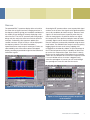
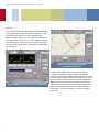
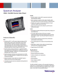
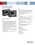
SA2600 Real-Time
Spectrum Analyzer
Handheld Real-Time
spectrum analyzer with
DPX™ technology
providing live RF view of
the spectrum
■
■
■
100% POI for transients with a
minimum duration of 500
microseconds
The SA2600 handheld real-time spectrum analyzer is ideal for a wide variety of
applications, ranging from small radio repair depots, to spectral interference
management in the field. Featuring true real-time DPX™ capability in a handheld
spectrum analyzer, the SA2600 offers practical solutions to discover short
transient spectral events that slip past conventional spectrum and batch
processing vector signal analyzers. The portability allows easy instrument
sharing in the laboratory environment and robust all-day battery operation in
the field, all with the largest display in its class. With field-ready, rugged hardware
featuring outstanding displayed average noise level (DANL), spurious free
dynamic range (SFDR), phase noise and easy LAN networking capability in a
portable unit, the SA2600 is a great choice for general purpose spectrum
measurements.
Features & Benefits
■
Discover
■
Locate
■
Revolutionary DPX™ spectrum processing
provides intuitive understanding of live RF
signals using colors based on frequency of
occurrence, displaying 2,500 spectrums per
sec with a 100% POI for transients with a
minimum duration of 500 microseconds
■
Find outdoor signals by plotting measurements
directly onto GPS-integrated maps
■
Find in-building signals with a Tap-and-Walkand-Tap interface using maps
■
Integrated mapping solution allows on-site
analysis of difficult problems
Rapid in-field detection and
location of elusive and
intermittent signals
Rugged handheld platform
optimized for field use
■
■
Datasheet | www.tektronix.com/SA2600
Input Frequency Range 10kHz-6.2GHz to
cover most modern signal sources
Unsurpassed ability to detect very low level
signals with -153dBm DANL at 10 Hz RBW
■
Ready for the Field
■
Benchtop spectrum analyzer performance in a
ruggedized handheld battery-operated field unit
■
Intuitive Windows CE-based touch screen intuitive
interface designed for field conditions
■
Backlit display, viewable in direct sunlight
■
Extended battery performance with
hot-swappable dual batteries
Datasheet | SA2600 Real-Time Spectrum Analyzer
The SA2600 has a variety of unique features such as
visual and audio signal strength indicators and integrated
GPS measurements’ mapping with direction-finding
vectors for easy location of signal emitters. Having 100%
probability of intercept for signals of 500 microseconds or
greater, and crystal-clear spectrograms, the SA2600 is an
ideal tool for surveying the RF spectrum, mapping
received signal strength and resolving spectral interference
disputes. It is perfect for engineers doing pre-deployment
analyses, signal strength mapping or troubleshooting
interference, as well as regulatory agencies who need
portable measurement capabilities suitable for today’s RF
systems.
Tektronix SA2600 Real-Time Spectrum Analyzer
2
The SA2600 is designed for general purpose field use in a
wide range of frequency bands and modulation types. It
incorporates a unique touch-screen interface that allows
very fast tuning and zooming in and out on signals, improving
operator efficiency when working across a wide range of
frequency bands. The SA2600 offers both performance
handheld spectrum analysis as well as innovative musthave technologies like DPX™ and GPS mapping at an
affordable price.
Discover
The patented DPX™ spectrum display offers an intuitive
live color view of signal transients changing over time in
the frequency domain, giving you immediate confidence in
the stability of your design or instantly displaying a fault
when it occurs. The Live RF spectrum processing engine
brings real time analysis of transient events to spectrum
analyzers. Performing 2,500 spectrum updates per
second, transients as brief as 500 µs can be displayed in
the frequency domain. This offers tremendous
improvement over swept analysis techniques. Events are
color-coded by rate of occurrence onto a bitmapped
display, providing unparalleled insight into the behavior of
intermittent signals.
Scanning the RF spectrum allows users to spot which signal
emitters are in the area. New signals with significant power
are usually candidates for further analysis. However, weak
signals can also be of interest, especially when they are
close to strong signals. Of particular interest are signals
that are present in the spectrum today but were not there
yesterday. Signals can be stored as reference and deviations
from this reference can be quickly identified using the trace
math feature. The SA2600 makes analysis easier by quickly
logging signals that are weak, bursty, hopping, time
multiplexed, or intentionally random. It takes advantage of
the FFT-based spectrum analysis capability to allow users
to see the true shape of the signal, even when it is bursty.
Masks can be automatically created from traces captured
earlier. You can compare this mask to the current trace and
if a mask violation occurs, the trace is logged. Finally,
when the spectrogram is paused, you can scroll through
the spectrogram’s time-axis and view the results.
Figure 1. DPX showing three hopping frequencies
Figure 2. Trace math showing signals not present
in the reference
www.tektronix.com/SA2600
3
Datasheet | SA2600 Real-Time Spectrum Analyzer
Locate
Once a signal of interest is identified, the SA2600 provides
various field-proven signal-hunting tools to locate it. For
the easier-to-find signals, the signal strength meter
produces audible tones that vary in pitch as a function of
the received power. The user can simply point the antenna
in the direction that receives maximum power. This allows
them to look for signals while watching their surroundings,
not the screen.
Figure 4. Color-coded measurements
for rapid in-field analysis
Figure 3. Signal strength for accurate signal finding
4
Harder to find signals, such as those influenced by
multipath, fading or low signal strength, the SA2600
provides several signal-mapping tools to facilitate hunting
for these signals. Maps can be imported from a variety of
formats using the PC-based iMap Converter application.
Signal intensity can be directly recorded, and directionfinding arrows can be directly placed on the map by the
user to show the directions where the signal intensity is
the greatest. Once you are done, you have a record of
your work.
Figure 5. Locating Interference with
integrated mapping solution
Analyzing mapped signals is a quick way to locate signals
that can be difficult to find otherwise. Traces can be
recorded on a map either manually or automatically.
Built-in GPS can be used to record signal position and
time data as the instrument moves.
The mapping functionality works indoors as well. Using the
unique “tap-and-walk-and-tap” interface, users tap on the
map to indicate a start location for data acquisition. The
end location is similarly recorded. The SA2600 captures
the data with the initial tap and follows a straight-line to
the end tap. It then displays the measurements, equally
spaced between these two measurement points.
Figure 6. Mapping signals Indoors
Ready for the field
The SA2600 will quickly scan the RF environment and help
you locate the interference sources with its field-proven
signal hunting tools. The instrument’s layout is designed in
a way that helps reduce the possibility of user mistakes
even if the issue is complex. The instrument does not get
in your way. The Windows CE-based touch screen
interface is designed specifically to enhance productivity
and navigation. While other solutions sometimes require
offline GPS and mapping software, the SA2600 includes
integrated GPS and mapping tools to allow more efficient
interference location capability. The extremely rugged,
rubberized magnesium alloy case is designed for harsh
field environments and can withstand drops and
mistreatment. With the optional second battery, the
SA2600 provides more than five hours of use for
continuous Spectrum Mode. The hot-swappable batteries
can dramatically extend the in-field usage time because
they can be replaced one at a time.
www.tektronix.com/SA2600
5
Datasheet | SA2600 Real-Time Spectrum Analyzer
SA2600 Ordering Guide
SA2600 Real-Time Spectrum Analyzer with DPX™
and built-in GPS (includes GPS antenna)
Standard Accessories
SA2600 Quick Start User Manual
SA2600 Installation software
AC Power Adapter
Lithium-Ion Battery
GPS Antenna
Tilt stand
Soft carry case
BNC Connector cover (2)
N Connector cover (1)
Audio jack mute plug (mute all audio output from
the instrument speaker)
Warranty
One year on parts and labor
Language Options
L0 SA2600 English manual
L99 No Manual Power Options
Power Options
A0 North America
A1 Universal EURO
A10 China
A11 India
A2 United Kingdom
A3 Australia
A5 Switzerland
A6 Japan
A99 No Power Cord or AC Adapter
Service Options
CA1 Provides a single calibration event or coverage
for the designated calibration interval, whichever
comes first.
C3 Calibration service - 3 years
C5 Calibration service - 5 years
D1 Calibration data report
D3 Calibration data report 3 years (with Option C3)
D5 Calibration data report 5 years (with Option C5)
R3 Repair service 3 years (including warranty)
R5 Repair service 5 years (including warranty)
6
Suggested Accessories
Antenna
Beam Antenna, 824 to 896 MHz: Order 119-6594-00
Beam Antenna, 896 to 960 MHz: Order 119-6595-00
Beam Antenna, 1710 to 1880 MHz: Order 119-6596-00
Beam Antenna, 1850 to 1990 MHz: Order 119-6597-00
Sniffer (Whip) antenna – Wideband (5 MHz to 1080 MHz) : Order 119-6609-00 (needs adapter 103-0045-00)
Magnetic Mount Antenna, 824 to 2170 MHz: Order 119-6970-00( needs adapter 103-0449-00
Filters
Pre-Filter, General Purpose, 824 to 2500 MHz, Type-N (f) Connector – Order 119-7246-00
Pre-Filter, General Purpose, 824 to 6200 MHz, Type-N (f) Connector – Order 119-7426-00
Cables
Cable, 50 Ω , BNC (m) 3 foot (91 cm): Order 012-0482-00
Cable, 50 Ω , Straight Type-N(m) and angled Type-N (m) connector, 1.6 foot (50 cm): Order 174-4977-00
Cable, 50 Ω , Type-N (m) to Type-N (m) connector, 3 foot (91 cm): Order 174-5002-00
Misc
External Charger: order 119-6030-00
AC Power Supply: order 119-6984-00
DC Vehicle Adapter: order 119-6028-00
Spare Lithium-Ion Battery: order 146-0151-00
Display Protector Sheets (5): order 016-1882-00
Specifications
General Performance Characteristics
Characteristic
Description
RF Input
Characteristic
10 kHz – 6.2 GHz
Maximum Operating
Input Level
+20 dBm peak envelope power
This is the maximum input level at which the
instrument will meet its performance specifications.
For a signal without any amplitude variation, peak
envelope power = rms.
50 W rms below 3.2 GHz
15 W rms between 3.2 GHz and 6.2 GHz
Range
Setting Resolution
Output Impedance
50 ohms
IF Center Frequency
140 MHz
IF 3 dB Bandwidth
24 MHz
Range
Setting Resolution
External Reference Input
Impedance
1500 ohms
Frequency Range
1 MHz up to 20 MHz ± 1 PPM in 1 MHz steps
Input Level Range
–15 dBm to +15 dBm, 1 MHz to 15 MHz
–10 dBm to +15 dBm, 16 MHz to 20 MHz
dBm levels assume 50 ohm source
10 Hz to 3 MHz (Manual RBW)
10 Hz to 1 MHz (Auto RBW)
1 Hz
Spectral Purity
Phase Noise
Internal Timebase
± 0.5 PPM from 0 °C to 50 °C
± 1.0 PPM aging/year
Twenty minute warm-up period required to meet accuracy specification
10 kHz to 6.2 GHz, preamp off
10 MHz to 6.2 GHz, preamp on
1 Hz
Span
Displayed Average Noise
Level, Preamp On
IF Output
Error
Description
Center Frequency
Operating Frequency
Range
Maximum Input Power
without Damage
Spectrum Analyzer Characteristics
Residual Spurious,
Preamp Off
Residual Spurious,
Preamp On
Third Order IMD
Second Harmonic
Input Related Spurious
Input Related Spurious,
exception frequencies,
typical
Third Order Intercept
–153 dBm, 10 MHz to 2 GHz, 10 Hz RBW
–152 dBm, 2 GHz to 4 GHz, 10 Hz RBW
–151 dBm, 4 to 5 GHz, 10 Hz RBW
–145 dBm, 5 to 6.2 GHz, 10 Hz RBW
Reference Level (DANL + 90 dB)
≤ -95 dBc/Hz @ 10 kHz offset
≤ –95 dBc/Hz @ 20 kHz offset
≤ –95 dBc/Hz @ 30 kHz offset
≤ –97 dBc/Hz @ 100 kHz offset
≤ –110 dBc/Hz @ 1 MHz offset
≤ –90 dBm, 0 dBm attenuator setting
Exception frequencies:
9 MHz to 19 MHz center frequency
3464 MHz center frequency
4592 MHz center frequency
5374 MHz to 5378 MHz center frequency
6160 MHz center frequency
≤ –105 dBm, 0 dBm attenuator setting
Exception frequencies:
9 MHz to 19 MHz center frequency
5374 MHz to 5378 MHz center frequency
≤ –70 dBc for two tones at or below the reference
level, preamp off, all gain settings Auto-coupled
≤ –60 dBc for a single tone at or below the reference
level, preamp off, all gain settings Auto-coupled
≤ –70 dBc except for Fin= 2.282 GHz ± 20 MHz
The reference for 'dBc' for this specification is the
total power of all signals present at the input of the
instrument regardless of the current span
≤ –55 dBc except for Fin= 2.282 GHz ± 20 MHz
The reference for “dBc” for this specification is the
total power of all signals present at the input of the
instrument regardless of the current span
≥ +7 dBm, 0 dB Input Attenuation, Preamp Off
www.tektronix.com/SA2600
7
Datasheet | SA2600 Real-Time Spectrum Analyzer
Spectral Display Amplitude
Reference
Level Range
Marker Power
Accuracy
General Purpose RF Measurements Characteristics
+20 dBm to –160 dBm
Characteristic Description
±1.75 dB, –50 dBm ≤ input ≤ +20 dBm, preamp off
±3.0 dB, –80 dBm ≤ input < –50 dBm, preamp on, above
10 MHz
±3.75 dB, –120 dBm ≤ input < –80 dBm, preamp on, above
10 MHz
Use peak detector for CW-like signals; use average detector for
wideband (signal >> RBW)
Accuracy guaranteed for CW signals and span set to 20 MHz or
less
General Purpose RF Channel Power Measurement
Display
Accuracy
Normal - updates display with each new result
Max Hold - updates displayed point only if new point > old
Min Hold - updates displayed point only if new point < old
Max/Min Hold - displays a vertical bar between Max Hold and
Min Hold
Average - displays average of N (specified by user) acquisitions
Display Modes Average is calculated as follows:
Last N values are saved in memory; when a new result is available,
the earliest result of the N stored values is discarded, the new
result is added to the stored values, and a new average is
calculated from the stored values
If the number of results is less than N, then all of the results are
averaged together
Number of
Averages
Measurement
Bandwidth Range
1 ≤ N ≤ 200
1 kHz - 20 MHz
≤ 1.2 dB; +20 dBm to –60 dBm; Resolution BW < 100 kHz
+20 dBm to –40 dBm; Resolution BW ≥ 100 kHz
1 MHz to 3.2 GHz , preamp off
≤ 2 .4 dB; –60 dBm to –75 dBm; Resolution BW < 100 kHz
–40 dBm to –55 dBm; Resolution BW ≥ 100 kHz
10 MHz to 3.2 GHz , preamp on
≤ 1.8 dB; +20 dBm to –50 dBm; Resolution BW < 100 kHz
+20 dBm to –40 dBm; Resolution BW ≥ 100 kHz
3.2 GHz to 6.2 GHz , preamp off
≤ 3 dB; –50 dBm to –75 dBm; Resolution BW < 100 kHz
–40 dBm to –55 dBm; Resolution BW ≥ 100 kHz
3.2 GHz to 6.2 GHz , preamp on
Specifications apply for default control settings
(Auto RBW, Auto Level)
Occupied Bandwidth Measurement
Percent Power
Inclusion Range
50% - 100%
RF Field Strength
Channel
Same as Channel Power
Bandwidth Range
Accuracy
Same as Channel Power
DPX™ Measurements Processing Characteristics
Characteristic
Description
Spectrum Processing Rate, nominal
2,500 per second (span independent)
Min Signal Duration for 100% Probability
500 µs
of Intercept, typical
Span Range
Mapping
Native Map Type
Graticule (.gsf)
Map types directly supported
MapInfo (*.mif)
Bitmap (*.bmp)
Other Map types accepted using
PC application iMap Converter
MapInfo (*.mif)
Bitmap (*.bmp)
Other raster formats
(*.gif, *.jpg, *.png, *.tif)
Google Earth
Microsoft MapPoint
USGS DLG (*.opt)
ESRI ArcInfo Shape (*.shp)
20 kHz to 20 MHz
Battery Life
5 hours of continuous Spectrum Mode (with optional second battery).
Actual life can be higher depending on usage.
8
Physical characteristics
Signal Analysis and Monitoring Characteristics
Characteristic
Description
Characteristic
Description
AM Demodulation
Provides an audio output signal after AM
demodulation of the user-selected signal
Dimensions
Height: 25.5 cm. (10.0 in)
Width: 33 cm. (13 in)
Depth: 12.5 cm. (4.8 in)
Weight
5.56 kg (12.27 lbs)
Measurement Frequency
As previously selected
Minimum Input Signal Level, Typical -100 dBm
Audio Measurement Bandwidth
8 kHz
Provides an audio output signal after FM
demodulation of the user-selected signal
FM Demodulation
Measurement Frequency
As previously selected
Minimum Signal Level, Typical
-100 dBm
Maximum Signal Deviation
Up to 100 kHz
Audio Measurement Bandwidth
8 kHz, 15 kHz, 75 kHz, or 200 kHz
Maximum Audio Output Bandwidth
15 kHz
Provides both an audio tone and a visual
display that are related to the strength
of the user selected signal
Signal Strength Indicator
Input Signal Level
-120 dBm, minimum
Measurement Frequency
As previously selected
Measurement Bandwidth
Up to 20 MHz, dependent upon span
and RBW setting
Tone Type
Variable beep rate or variable frequency
Update Rate, Typical
10 per second
Display characteristics
Characteristic
Description
Color Display
10.4 in. (diagonal), transflective LCD
Resolution: 640x480 (VGA)
Miscellaneous characteristics
Characteristic
Description
Recommended Instrument Calibration Interval
2 years
Safety compliance
Characteristic
ANSI/UL61010-1:2004
Electrical Equipment for Measurement, Control, and
Laboratory Use.
Environmental characteristics
Characteristic
Description
Temperature
Operating: 0 °C to +50 °C specified performance,
–10 °C to +50 °C, typical
Nonoperating: –40 °C to +60 °C
The temperature specs above are modified with the
following options installed: Li-Ion Batteries: Charge 0 °C
to +45 °C, Storage –20 °C to +60 °C
Humidity
Operating and Nonoperating: 5% to 95% relative
humidity (RH) at up to +30 °C, 5% to 45% RH above
+30 °C up to +50 °C, noncondensing
Altitude
Operating: Up to 4,600 meters (15,092 feet)
Nonoperating: Up to 12,192 meters (40,000 feet)
Description
CSA C22.2 No. 61010.1:2004
Electrical Equipment for Measurement, Control, and
Laboratory Use.
Safety Compliance
EN 61010-1:2001
Electrical Equipment for Measurement, Control, and
Laboratory Use.
IEC61010-1:2001
Electrical Equipment for Measurement, Control, and
Laboratory Use.
ISA 82.02.01
Electrical Equipment for Measurement, Control, and
Laboratory Use.
www.tektronix.com/SA2600
9
Datasheet | SA2600 Real-Time Spectrum Analyzer
About Tektronix:
For Further Information:
Tektronix has more than 60 years of experience in providing network
operators and equipment manufacturers a comprehensive and
unparalleled suite of network diagnostics and management solutions
for fixed, mobile, IP and converged multi-service networks.
Tektronix maintains a comprehensive, constantly
expanding collection of application notes, technical
briefs and other resources to help engineers working
on the cutting edge of technology.
Please visit www.tektronix.com/communications
These solutions support architectures and applications such as fixed
mobile convergence, IMS, broadband wireless access, WiMAX, VoIP
and triple play, including IPTV.
Contact Tektronix:
Please visit www.tektronix.com/communications
Learn more about Tektronix' communications test, measurement and
network monitoring solutions by visiting:
www.tektronix.com/communications
Phone:
1-800-833-9200 option 1
+1-469-330-4000
Locate your nearest Tektronix representative at:
www.tektronix.com/contactus
Copyright © Tektronix. All rights reserved. Tektronix products are covered by U.S. and foreign patents, issued and pending. Information in this publication supersedes that in all previously published material. Specification and price change
privileges reserved. TEKTRONIX and TEK are registered trademarks of Tektronix, Inc. All other trade names referenced
are the service marks, trademarks or registered trademarks of their respective companies.
06/08 | CWW-22258-0