1
Applied Biosystems ViiA™ 7
Real-Time PCR System
Calibration, Maintenance, Networking, and Security
User Guide
Applied Biosystems ViiA™ 7
Real-Time PCR System
Calibration, Maintenance, Networking, and Security
User Guide
For Research Use Only. Not intended for any animal or human therapeutic or diagnostic use.
Information in this document is subject to change without notice.
APPLIED BIOSYSTEMS DISCLAIMS ALL WARRANTIES WITH RESPECT TO THIS DOCUMENT, EXPRESSED OR IMPLIED, INCLUDING BUT NOT LIMITED TO
THOSE OF MERCHANTABILITY OR FITNESS FOR A PARTICULAR PURPOSE. TO THE FULLEST EXTENT ALLOWED BY LAW, IN NO EVENT SHALL APPLIED
BIOSYSTEMS BE LIABLE, WHETHER IN CONTRACT, TORT, WARRANTY, OR UNDER ANY STATUTE OR ON ANY OTHER BASIS FOR SPECIAL, INCIDENTAL,
INDIRECT, PUNITIVE, MULTIPLE OR CONSEQUENTIAL DAMAGES IN CONNECTION WITH OR ARISING FROM THIS DOCUMENT, INCLUDING BUT NOT
LIMITED TO THE USE THEREOF, WHETHER OR NOT FORESEEABLE AND WHETHER OR NOT APPLIED BIOSYSTEMS IS ADVISED OF THE POSSIBILITY OF
SUCH DAMAGES.
NOTICE TO PURCHASER: Label License
No right is conveyed expressly, by implication, or by estoppel under any other patent claim, such as claims to apparatus, reagents, kits, or methods such as
5′ nuclease methods, other than apparatus claims covering the purchased apparatus. Further information on purchasing licenses may be obtained by
contacting the Director of Licensing, Applied Biosystems, 850 Lincoln Centre Drive, Foster City, California 94404, USA.
TRADEMARKS
The trademarks mentioned herein are the property of Life Technologies Corporation or their respective owners.
TaqMan is a registered trademark of Roche Molecular Systems, Inc. Twister is a trademark of Caliper Life Sciences. Apple, Safari, and Macintosh are
trademarks of Apple Inc. Microsoft and Internet Explorer are trademarks of Microsoft Corporation. Mozilla is a trademark of Mozilla Foundation.
© 2010 Life Technologies Corporation. All rights reserved.
Part Number 4442661 Rev. C
12/2010
Contents
About This Guide . . . . . . . . . . . . . . . . . . . . . . . . . . . . . . . . . . . . . . . . . . 13
Purpose . . . . . . . . . . . . . . . . . . . . . . . . . . . . . . . . . . . . . . . . . . . . . . . . . . . . . . . . . . . . . . . . . . . . . . . 13
Audience . . . . . . . . . . . . . . . . . . . . . . . . . . . . . . . . . . . . . . . . . . . . . . . . . . . . . . . . . . . . . . . . . . . . . . 13
Assumptions . . . . . . . . . . . . . . . . . . . . . . . . . . . . . . . . . . . . . . . . . . . . . . . . . . . . . . . . . . . . . . . . . . . 13
Safety information . . . . . . . . . . . . . . . . . . . . . . . . . . . . . . . . . . . . . . . . . . . . . . . . . . . . . . . . . . . . . . 14
Safety alert words . . . . . . . . . . . . . . . . . . . . . . . . . . . . . . . . . . . . . . . . . . . . . . . . . . . . . . . . . . 14
SDSs . . . . . . . . . . . . . . . . . . . . . . . . . . . . . . . . . . . . . . . . . . . . . . . . . . . . . . . . . . . . . . . . . . . . . 14
Safety labels on instruments . . . . . . . . . . . . . . . . . . . . . . . . . . . . . . . . . . . . . . . . . . . . . . . . 15
CHAPTER 1
Getting Started . . . . . . . . . . . . . . . . . . . . . . . . . . . . . . . . . . . . . . . . . . . . 17
About the ViiA™ 7 System . . . . . . . . . . . . . . . . . . . . . . . . . . . . . . . . . . . . . . . . . . . . . . . . . . . . . . . . 18
About data collection . . . . . . . . . . . . . . . . . . . . . . . . . . . . . . . . . . . . . . . . . . . . . . . . . . . . . . . 18
Instrument filters and supported dyes . . . . . . . . . . . . . . . . . . . . . . . . . . . . . . . . . . . . . . . . 19
Specifications and layout . . . . . . . . . . . . . . . . . . . . . . . . . . . . . . . . . . . . . . . . . . . . . . . . . . . . . . . . 20
ViiA™ 7 System specifications . . . . . . . . . . . . . . . . . . . . . . . . . . . . . . . . . . . . . . . . . . . . . . . . 20
ViiA™ 7 System layout and connections . . . . . . . . . . . . . . . . . . . . . . . . . . . . . . . . . . . . . . . . 23
ViiA™ 7 System hardware . . . . . . . . . . . . . . . . . . . . . . . . . . . . . . . . . . . . . . . . . . . . . . . . . . . . . . . . 24
Instrument components . . . . . . . . . . . . . . . . . . . . . . . . . . . . . . . . . . . . . . . . . . . . . . . . . . . . 24
Bar code readers . . . . . . . . . . . . . . . . . . . . . . . . . . . . . . . . . . . . . . . . . . . . . . . . . . . . . . . . . . 26
Twister® II Robot components . . . . . . . . . . . . . . . . . . . . . . . . . . . . . . . . . . . . . . . . . . . . . . . 27
Electrical protective devices . . . . . . . . . . . . . . . . . . . . . . . . . . . . . . . . . . . . . . . . . . . . . . . . . 29
ViiA™ 7 System software . . . . . . . . . . . . . . . . . . . . . . . . . . . . . . . . . . . . . . . . . . . . . . . . . . . . . . . . . 30
Computer requirements . . . . . . . . . . . . . . . . . . . . . . . . . . . . . . . . . . . . . . . . . . . . . . . . . . . . 30
Software installation . . . . . . . . . . . . . . . . . . . . . . . . . . . . . . . . . . . . . . . . . . . . . . . . . . . . . . . 30
Third-party software . . . . . . . . . . . . . . . . . . . . . . . . . . . . . . . . . . . . . . . . . . . . . . . . . . . . . . . 31
Using this guide . . . . . . . . . . . . . . . . . . . . . . . . . . . . . . . . . . . . . . . . . . . . . . . . . . . . . . . . . . . . . . . . 32
Applied Biosystems ViiA™ 7 Real-Time PCR System User Guide:
Calibration, Maintenance, Networking, and Security
5
Contents
CHAPTER 2
Calibration and Maintenance . . . . . . . . . . . . . . . . . . . . . . . . . . . . . . . 33
Calibrate and maintain the ViiA™ 7 System . . . . . . . . . . . . . . . . . . . . . . . . . . . . . . . . . . . . . . . . . 34
Recommended calibration and maintenance schedule . . . . . . . . . . . . . . . . . . . . . . . . . . 34
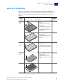
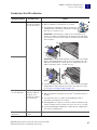
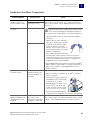
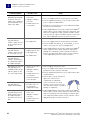
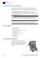
About the consumables . . . . . . . . . . . . . . . . . . . . . . . . . . . . . . . . . . . . . . . . . . . . . . . . . . . . . . . . . 35
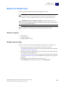
Perform regular data maintenance . . . . . . . . . . . . . . . . . . . . . . . . . . . . . . . . . . . . . . . . . . . . . . .
Maintain the computer hard drives . . . . . . . . . . . . . . . . . . . . . . . . . . . . . . . . . . . . . . . . . . .
Archive and back up experiment files . . . . . . . . . . . . . . . . . . . . . . . . . . . . . . . . . . . . . . . . .
Back up the instrument settings . . . . . . . . . . . . . . . . . . . . . . . . . . . . . . . . . . . . . . . . . . . . .
37
37
37
37
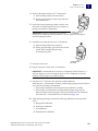
Fill the array cards . . . . . . . . . . . . . . . . . . . . . . . . . . . . . . . . . . . . . . . . . . . . . . . . . . . . . . . . . . . . . 38
Materials required . . . . . . . . . . . . . . . . . . . . . . . . . . . . . . . . . . . . . . . . . . . . . . . . . . . . . . . . . 38
Fill the calibration array cards . . . . . . . . . . . . . . . . . . . . . . . . . . . . . . . . . . . . . . . . . . . . . . . 38
6
Perform the ROI calibration . . . . . . . . . . . . . . . . . . . . . . . . . . . . . . . . . . . . . . . . . . . . . . . . . . . . . .
Materials required . . . . . . . . . . . . . . . . . . . . . . . . . . . . . . . . . . . . . . . . . . . . . . . . . . . . . . . . .
When to perform the calibration . . . . . . . . . . . . . . . . . . . . . . . . . . . . . . . . . . . . . . . . . . . . .
About the ROI calibration data . . . . . . . . . . . . . . . . . . . . . . . . . . . . . . . . . . . . . . . . . . . . . . .
Prepare the calibration plate or array card . . . . . . . . . . . . . . . . . . . . . . . . . . . . . . . . . . . .
Perform the calibration . . . . . . . . . . . . . . . . . . . . . . . . . . . . . . . . . . . . . . . . . . . . . . . . . . . . .
Troubleshoot the ROI calibration . . . . . . . . . . . . . . . . . . . . . . . . . . . . . . . . . . . . . . . . . . . . .
42
42
42
43
43
45
47
Perform the background calibration . . . . . . . . . . . . . . . . . . . . . . . . . . . . . . . . . . . . . . . . . . . . . .
Materials required . . . . . . . . . . . . . . . . . . . . . . . . . . . . . . . . . . . . . . . . . . . . . . . . . . . . . . . . .
When to perform the calibration . . . . . . . . . . . . . . . . . . . . . . . . . . . . . . . . . . . . . . . . . . . . .
About the background calibration data . . . . . . . . . . . . . . . . . . . . . . . . . . . . . . . . . . . . . . . .
Prepare the background plate or array card . . . . . . . . . . . . . . . . . . . . . . . . . . . . . . . . . . .
Perform the calibration . . . . . . . . . . . . . . . . . . . . . . . . . . . . . . . . . . . . . . . . . . . . . . . . . . . . .
Troubleshoot the background calibration . . . . . . . . . . . . . . . . . . . . . . . . . . . . . . . . . . . . . .
48
48
48
49
49
51
53
Perform the uniformity calibration . . . . . . . . . . . . . . . . . . . . . . . . . . . . . . . . . . . . . . . . . . . . . . . .
Materials required . . . . . . . . . . . . . . . . . . . . . . . . . . . . . . . . . . . . . . . . . . . . . . . . . . . . . . . . .
When to perform the calibration . . . . . . . . . . . . . . . . . . . . . . . . . . . . . . . . . . . . . . . . . . . . .
About the uniformity calibration data . . . . . . . . . . . . . . . . . . . . . . . . . . . . . . . . . . . . . . . . .
Prepare the calibration plate or array card . . . . . . . . . . . . . . . . . . . . . . . . . . . . . . . . . . . .
Perform the calibration . . . . . . . . . . . . . . . . . . . . . . . . . . . . . . . . . . . . . . . . . . . . . . . . . . . . .
Troubleshoot the uniformity calibration . . . . . . . . . . . . . . . . . . . . . . . . . . . . . . . . . . . . . . .
55
55
55
55
56
57
59
Perform the dye calibration . . . . . . . . . . . . . . . . . . . . . . . . . . . . . . . . . . . . . . . . . . . . . . . . . . . . . .
Materials required . . . . . . . . . . . . . . . . . . . . . . . . . . . . . . . . . . . . . . . . . . . . . . . . . . . . . . . . .
When to perform the dye calibrations . . . . . . . . . . . . . . . . . . . . . . . . . . . . . . . . . . . . . . . . .
About the dye calibration . . . . . . . . . . . . . . . . . . . . . . . . . . . . . . . . . . . . . . . . . . . . . . . . . . .
Prepare the calibration plates/array cards . . . . . . . . . . . . . . . . . . . . . . . . . . . . . . . . . . . .
Perform the calibration . . . . . . . . . . . . . . . . . . . . . . . . . . . . . . . . . . . . . . . . . . . . . . . . . . . . .
Troubleshoot the dye calibration . . . . . . . . . . . . . . . . . . . . . . . . . . . . . . . . . . . . . . . . . . . . .
60
60
61
62
64
65
68
Applied Biosystems ViiA™ 7 Real-Time PCR System User Guide:
Calibration, Maintenance, Networking, and Security
Contents
Perform the normalization calibration . . . . . . . . . . . . . . . . . . . . . . . . . . . . . . . . . . . . . . . . . . . . . 69
Materials required . . . . . . . . . . . . . . . . . . . . . . . . . . . . . . . . . . . . . . . . . . . . . . . . . . . . . . . . . 69
When to perform the calibration . . . . . . . . . . . . . . . . . . . . . . . . . . . . . . . . . . . . . . . . . . . . . 69
About the normalization calibration data . . . . . . . . . . . . . . . . . . . . . . . . . . . . . . . . . . . . . . 69
Prepare the calibration plate or array card . . . . . . . . . . . . . . . . . . . . . . . . . . . . . . . . . . . . 70
Perform the calibration . . . . . . . . . . . . . . . . . . . . . . . . . . . . . . . . . . . . . . . . . . . . . . . . . . . . . 71
Troubleshoot the normalization calibration . . . . . . . . . . . . . . . . . . . . . . . . . . . . . . . . . . . . 73
Verify the instrument performance . . . . . . . . . . . . . . . . . . . . . . . . . . . . . . . . . . . . . . . . . . . . . . . 74
Materials required . . . . . . . . . . . . . . . . . . . . . . . . . . . . . . . . . . . . . . . . . . . . . . . . . . . . . . . . . 74
When to perform the RNase P instrument verification experiment . . . . . . . . . . . . . . . . 74
About the RNase P kits . . . . . . . . . . . . . . . . . . . . . . . . . . . . . . . . . . . . . . . . . . . . . . . . . . . . . 75
About the analysis . . . . . . . . . . . . . . . . . . . . . . . . . . . . . . . . . . . . . . . . . . . . . . . . . . . . . . . . . 76
Installation specification . . . . . . . . . . . . . . . . . . . . . . . . . . . . . . . . . . . . . . . . . . . . . . . . . . . . 76
Prepare the TaqMan® RNase P plate or array card . . . . . . . . . . . . . . . . . . . . . . . . . . . . . 77
Run the experiment . . . . . . . . . . . . . . . . . . . . . . . . . . . . . . . . . . . . . . . . . . . . . . . . . . . . . . . . 79
Troubleshoot the RNase P experiment . . . . . . . . . . . . . . . . . . . . . . . . . . . . . . . . . . . . . . . . 83
CHAPTER 3
Networking . . . . . . . . . . . . . . . . . . . . . . . . . . . . . . . . . . . . . . . . . . . . . . . 87
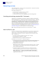
Networking overview . . . . . . . . . . . . . . . . . . . . . . . . . . . . . . . . . . . . . . . . . . . . . . . . . . . . . . . . . . . . 88
Controlling and monitoring networked ViiA™ 7 Instruments . . . . . . . . . . . . . . . . . . . . . . 88
About the Ethernet 1 port . . . . . . . . . . . . . . . . . . . . . . . . . . . . . . . . . . . . . . . . . . . . . . . . . . . 88
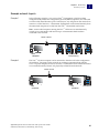
Example network layouts . . . . . . . . . . . . . . . . . . . . . . . . . . . . . . . . . . . . . . . . . . . . . . . . . . . 89
Networking guidelines and best practices . . . . . . . . . . . . . . . . . . . . . . . . . . . . . . . . . . . . . 90
Network setup workflow . . . . . . . . . . . . . . . . . . . . . . . . . . . . . . . . . . . . . . . . . . . . . . . . . . . . . . . . 90
Collect the required network information . . . . . . . . . . . . . . . . . . . . . . . . . . . . . . . . . . . . . . . . . . 91
Connect the ViiA™ 7 Instrument to the network . . . . . . . . . . . . . . . . . . . . . . . . . . . . . . . . . . . . . 91
Materials required . . . . . . . . . . . . . . . . . . . . . . . . . . . . . . . . . . . . . . . . . . . . . . . . . . . . . . . . . 91
Define the ViiA™ 7 Instrument internet protocol settings . . . . . . . . . . . . . . . . . . . . . . . . . 91
Connect the computer to the network . . . . . . . . . . . . . . . . . . . . . . . . . . . . . . . . . . . . . . . . . . . . . 92
Materials required . . . . . . . . . . . . . . . . . . . . . . . . . . . . . . . . . . . . . . . . . . . . . . . . . . . . . . . . . 92
Computer requirement . . . . . . . . . . . . . . . . . . . . . . . . . . . . . . . . . . . . . . . . . . . . . . . . . . . . . 92
Collect required information . . . . . . . . . . . . . . . . . . . . . . . . . . . . . . . . . . . . . . . . . . . . . . . . . 92
Set up the computer . . . . . . . . . . . . . . . . . . . . . . . . . . . . . . . . . . . . . . . . . . . . . . . . . . . . . . . . 92
Install the ViiA™ 7 Software . . . . . . . . . . . . . . . . . . . . . . . . . . . . . . . . . . . . . . . . . . . . . . . . . . 93
Monitor the ViiA™ 7 Instrument . . . . . . . . . . . . . . . . . . . . . . . . . . . . . . . . . . . . . . . . . . . . . . . . . . . 94
About remote monitoring . . . . . . . . . . . . . . . . . . . . . . . . . . . . . . . . . . . . . . . . . . . . . . . . . . . 94
Monitor the status of ViiA™ 7 Instrument during a run . . . . . . . . . . . . . . . . . . . . . . . . . . . 94
Upload or download an experiment or template to a ViiA™ 7 Instrument . . . . . . . . . . . 95
Enable or change the calibration reminders . . . . . . . . . . . . . . . . . . . . . . . . . . . . . . . . . . . 96
Applied Biosystems ViiA™ 7 Real-Time PCR System User Guide:
Calibration, Maintenance, Networking, and Security
7
Contents
CHAPTER 4
Security, Audit, and Electronic Signature . . . . . . . . . . . . . . . . . . . . 99
Section 4.1 Administrators . . . . . . . . . . . . . . . . . . . . . . . . . . . . . . . . . . . . . . . . . . . 101
Administrators overview . . . . . . . . . . . . . . . . . . . . . . . . . . . . . . . . . . . . . . . . . . . . . . . . . . . . . . . 101
Example applications . . . . . . . . . . . . . . . . . . . . . . . . . . . . . . . . . . . . . . . . . . . . . . . . . . . . . 102
Configure the security system . . . . . . . . . . . . . . . . . . . . . . . . . . . . . . . . . . . . . . . . . . . . . . . . . . . 103
Access the Security screen and enable or disable security . . . . . . . . . . . . . . . . . . . . . . 103
Set account setup and security policies . . . . . . . . . . . . . . . . . . . . . . . . . . . . . . . . . . . . . . 104
Set up messaging notifications . . . . . . . . . . . . . . . . . . . . . . . . . . . . . . . . . . . . . . . . . . . . . 105
Manage user accounts . . . . . . . . . . . . . . . . . . . . . . . . . . . . . . . . . . . . . . . . . . . . . . . . . . . . . . . . . 106
Create or edit a user account . . . . . . . . . . . . . . . . . . . . . . . . . . . . . . . . . . . . . . . . . . . . . . . 106
Determine the name of the logged-in user . . . . . . . . . . . . . . . . . . . . . . . . . . . . . . . . . . . 107
Create or edit a user role . . . . . . . . . . . . . . . . . . . . . . . . . . . . . . . . . . . . . . . . . . . . . . . . . . 107
View and print a user report . . . . . . . . . . . . . . . . . . . . . . . . . . . . . . . . . . . . . . . . . . . . . . . . 109
Manage auditing . . . . . . . . . . . . . . . . . . . . . . . . . . . . . . . . . . . . . . . . . . . . . . . . . . . . . . . . . . . . . . 110
Access the Audit screen and enable or disable auditing . . . . . . . . . . . . . . . . . . . . . . . . 110
Select objects to audit . . . . . . . . . . . . . . . . . . . . . . . . . . . . . . . . . . . . . . . . . . . . . . . . . . . . . 110
Create audit reason settings . . . . . . . . . . . . . . . . . . . . . . . . . . . . . . . . . . . . . . . . . . . . . . . 110
Generate audit reports . . . . . . . . . . . . . . . . . . . . . . . . . . . . . . . . . . . . . . . . . . . . . . . . . . . . . . . . . 111
Display audit histories from the Security Settings dialog box . . . . . . . . . . . . . . . . . . . . 111
Display audit histories for an experiment, template, or study . . . . . . . . . . . . . . . . . . . 114
Manage electronic signature . . . . . . . . . . . . . . . . . . . . . . . . . . . . . . . . . . . . . . . . . . . . . . . . . . . . 116
Access the e-Signature Settings screen and enable or disable e-sig . . . . . . . . . . . . . 116
Configure the meanings of the electronic signatures . . . . . . . . . . . . . . . . . . . . . . . . . . 116
Configure the e-signature rights for user roles . . . . . . . . . . . . . . . . . . . . . . . . . . . . . . . 117
Select the actions that require signature . . . . . . . . . . . . . . . . . . . . . . . . . . . . . . . . . . . . . 117
How the software prompts electronic signature . . . . . . . . . . . . . . . . . . . . . . . . . . . . . . . 118
Generate e-signature reports . . . . . . . . . . . . . . . . . . . . . . . . . . . . . . . . . . . . . . . . . . . . . . . . . . . 119
Display the e-sig records . . . . . . . . . . . . . . . . . . . . . . . . . . . . . . . . . . . . . . . . . . . . . . . . . . 119
Save or print e-sig records . . . . . . . . . . . . . . . . . . . . . . . . . . . . . . . . . . . . . . . . . . . . . . . . . 119
Save or print the table of e-signature events . . . . . . . . . . . . . . . . . . . . . . . . . . . . . . . . . . 119
Export and import user, security, audit, and e-signature settings . . . . . . . . . . . . . . . . . . . . . 120
Export . . . . . . . . . . . . . . . . . . . . . . . . . . . . . . . . . . . . . . . . . . . . . . . . . . . . . . . . . . . . . . . . . . . 120
Import . . . . . . . . . . . . . . . . . . . . . . . . . . . . . . . . . . . . . . . . . . . . . . . . . . . . . . . . . . . . . . . . . . 120
Section 4.2 Users . . . . . . . . . . . . . . . . . . . . . . . . . . . . . . . . . . . . . . . . . . . . . . . . . . . . 121
Users overview . . . . . . . . . . . . . . . . . . . . . . . . . . . . . . . . . . . . . . . . . . . . . . . . . . . . . . . . . . . . . . . . 121
Security . . . . . . . . . . . . . . . . . . . . . . . . . . . . . . . . . . . . . . . . . . . . . . . . . . . . . . . . . . . . . . . . . . . . . .
Log in . . . . . . . . . . . . . . . . . . . . . . . . . . . . . . . . . . . . . . . . . . . . . . . . . . . . . . . . . . . . . . . . . . .
Permissions . . . . . . . . . . . . . . . . . . . . . . . . . . . . . . . . . . . . . . . . . . . . . . . . . . . . . . . . . . . . .
Change your password when it expires . . . . . . . . . . . . . . . . . . . . . . . . . . . . . . . . . . . . . .
Account suspension . . . . . . . . . . . . . . . . . . . . . . . . . . . . . . . . . . . . . . . . . . . . . . . . . . . . . . .
Session time-out . . . . . . . . . . . . . . . . . . . . . . . . . . . . . . . . . . . . . . . . . . . . . . . . . . . . . . . . .
121
121
121
121
122
122
Audit . . . . . . . . . . . . . . . . . . . . . . . . . . . . . . . . . . . . . . . . . . . . . . . . . . . . . . . . . . . . . . . . . . . . . . . . 122
Electronic signature . . . . . . . . . . . . . . . . . . . . . . . . . . . . . . . . . . . . . . . . . . . . . . . . . . . . . . . . . . . 122
8
Applied Biosystems ViiA™ 7 Real-Time PCR System User Guide:
Calibration, Maintenance, Networking, and Security
Contents
CHAPTER 5
Service . . . . . . . . . . . . . . . . . . . . . . . . . . . . . . . . . . . . . . . . . . . . . . . . . . 123
Decontaminate the sample block . . . . . . . . . . . . . . . . . . . . . . . . . . . . . . . . . . . . . . . . . . . . . . . . 124
Materials required . . . . . . . . . . . . . . . . . . . . . . . . . . . . . . . . . . . . . . . . . . . . . . . . . . . . . . . . 124
How to handle the sample block . . . . . . . . . . . . . . . . . . . . . . . . . . . . . . . . . . . . . . . . . . . . 124
Clean the sample block . . . . . . . . . . . . . . . . . . . . . . . . . . . . . . . . . . . . . . . . . . . . . . . . . . . . 125
Replace the halogen lamp . . . . . . . . . . . . . . . . . . . . . . . . . . . . . . . . . . . . . . . . . . . . . . . . . . . . . . 127
Materials required . . . . . . . . . . . . . . . . . . . . . . . . . . . . . . . . . . . . . . . . . . . . . . . . . . . . . . . . 127
Halogen lamp warnings . . . . . . . . . . . . . . . . . . . . . . . . . . . . . . . . . . . . . . . . . . . . . . . . . . . 127
Check the lamp status . . . . . . . . . . . . . . . . . . . . . . . . . . . . . . . . . . . . . . . . . . . . . . . . . . . . . 128
Replace the lamp . . . . . . . . . . . . . . . . . . . . . . . . . . . . . . . . . . . . . . . . . . . . . . . . . . . . . . . . . 128
Replace the instrument fuses . . . . . . . . . . . . . . . . . . . . . . . . . . . . . . . . . . . . . . . . . . . . . . . . . . . 130
Materials required . . . . . . . . . . . . . . . . . . . . . . . . . . . . . . . . . . . . . . . . . . . . . . . . . . . . . . . . 130
Replace the fuses . . . . . . . . . . . . . . . . . . . . . . . . . . . . . . . . . . . . . . . . . . . . . . . . . . . . . . . . . 130
Update the Windows® operating system . . . . . . . . . . . . . . . . . . . . . . . . . . . . . . . . . . . . . . . . . . 131
Update the ViiA™ 7 Software and Firmware . . . . . . . . . . . . . . . . . . . . . . . . . . . . . . . . . . . . . . . . 132
Update the ViiA™ 7 Software . . . . . . . . . . . . . . . . . . . . . . . . . . . . . . . . . . . . . . . . . . . . . . . . 132
Update the ViiA™ 7 Instrument firmware . . . . . . . . . . . . . . . . . . . . . . . . . . . . . . . . . . . . . 132
Manage ViiA™ 7 Software licenses . . . . . . . . . . . . . . . . . . . . . . . . . . . . . . . . . . . . . . . . . . . . . . . . 133
About ViiA™ 7 Software license keys and files . . . . . . . . . . . . . . . . . . . . . . . . . . . . . . . . . 133
Manage licenses . . . . . . . . . . . . . . . . . . . . . . . . . . . . . . . . . . . . . . . . . . . . . . . . . . . . . . . . . . 133
Replace the sample block . . . . . . . . . . . . . . . . . . . . . . . . . . . . . . . . . . . . . . . . . . . . . . . . . . . . . . 135
Materials required . . . . . . . . . . . . . . . . . . . . . . . . . . . . . . . . . . . . . . . . . . . . . . . . . . . . . . . . 135
How to handle the sample block . . . . . . . . . . . . . . . . . . . . . . . . . . . . . . . . . . . . . . . . . . . . 135
Replace the sample block . . . . . . . . . . . . . . . . . . . . . . . . . . . . . . . . . . . . . . . . . . . . . . . . . . 135
Replace the heated cover . . . . . . . . . . . . . . . . . . . . . . . . . . . . . . . . . . . . . . . . . . . . . . . . . . . . . . . 137
Materials required . . . . . . . . . . . . . . . . . . . . . . . . . . . . . . . . . . . . . . . . . . . . . . . . . . . . . . . . 137
How to handle the heated cover . . . . . . . . . . . . . . . . . . . . . . . . . . . . . . . . . . . . . . . . . . . . . 137
Replace the heated cover . . . . . . . . . . . . . . . . . . . . . . . . . . . . . . . . . . . . . . . . . . . . . . . . . . 137
Replace the plate adapter . . . . . . . . . . . . . . . . . . . . . . . . . . . . . . . . . . . . . . . . . . . . . . . . . . . . . . 139
Materials required . . . . . . . . . . . . . . . . . . . . . . . . . . . . . . . . . . . . . . . . . . . . . . . . . . . . . . . . 139
Replace the plate adapter . . . . . . . . . . . . . . . . . . . . . . . . . . . . . . . . . . . . . . . . . . . . . . . . . . 139
APPENDIX A
Manual Instrument Operation . . . . . . . . . . . . . . . . . . . . . . . . . . . . . 141
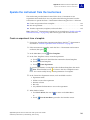
Overview . . . . . . . . . . . . . . . . . . . . . . . . . . . . . . . . . . . . . . . . . . . . . . . . . . . . . . . . . . . . . . . . . . . . . 142
Functions available from the instrument touchscreen . . . . . . . . . . . . . . . . . . . . . . . . . 142
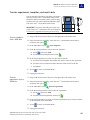
Operate the instrument from the touchscreen . . . . . . . . . . . . . . . . . . . . . . . . . . . . . . . . . . . . . 143
Create an experiment from a template . . . . . . . . . . . . . . . . . . . . . . . . . . . . . . . . . . . . . . . 143
Run an experiment . . . . . . . . . . . . . . . . . . . . . . . . . . . . . . . . . . . . . . . . . . . . . . . . . . . . . . . . 144
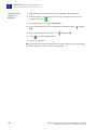
Transfer experiments, templates, and results data . . . . . . . . . . . . . . . . . . . . . . . . . . . . 145
Maintain the instrument from the touchscreen . . . . . . . . . . . . . . . . . . . . . . . . . . . . . . . . . . . . 147
Back up and restore the instrument settings . . . . . . . . . . . . . . . . . . . . . . . . . . . . . . . . . 148
Perform an instrument self test . . . . . . . . . . . . . . . . . . . . . . . . . . . . . . . . . . . . . . . . . . . . 149
Update the instrument firmware . . . . . . . . . . . . . . . . . . . . . . . . . . . . . . . . . . . . . . . . . . . . 150
Applied Biosystems ViiA™ 7 Real-Time PCR System User Guide:
Calibration, Maintenance, Networking, and Security
9
Contents
Administrate the instrument from the touchscreen . . . . . . . . . . . . . . . . . . . . . . . . . . . . . . . . 151
Define the date and time . . . . . . . . . . . . . . . . . . . . . . . . . . . . . . . . . . . . . . . . . . . . . . . . . . . 152
Define the instrument settings . . . . . . . . . . . . . . . . . . . . . . . . . . . . . . . . . . . . . . . . . . . . . 152
Define the maintenance reminders . . . . . . . . . . . . . . . . . . . . . . . . . . . . . . . . . . . . . . . . . 153
Define the network settings . . . . . . . . . . . . . . . . . . . . . . . . . . . . . . . . . . . . . . . . . . . . . . . . 154
Define the system shortcuts . . . . . . . . . . . . . . . . . . . . . . . . . . . . . . . . . . . . . . . . . . . . . . . . 155
Review the instrument statistics . . . . . . . . . . . . . . . . . . . . . . . . . . . . . . . . . . . . . . . . . . . . 155
Enable or disable instrument security . . . . . . . . . . . . . . . . . . . . . . . . . . . . . . . . . . . . . . . 156
View the instrument log . . . . . . . . . . . . . . . . . . . . . . . . . . . . . . . . . . . . . . . . . . . . . . . . . . . 157
APPENDIX B
Power On or Off, Store, and Move the ViiA™ 7 System . . . . . . . . 159
Place the ViiA™ 7 System on standby . . . . . . . . . . . . . . . . . . . . . . . . . . . . . . . . . . . . . . . . . . . . . 160
Power on the ViiA™ 7 System . . . . . . . . . . . . . . . . . . . . . . . . . . . . . . . . . . . . . . . . . . . . . . . . . . . . 160
Power off the ViiA™ 7 System . . . . . . . . . . . . . . . . . . . . . . . . . . . . . . . . . . . . . . . . . . . . . . . . . . . . 161
Store the ViiA™ 7 System . . . . . . . . . . . . . . . . . . . . . . . . . . . . . . . . . . . . . . . . . . . . . . . . . . . . . . . . 162
Materials required . . . . . . . . . . . . . . . . . . . . . . . . . . . . . . . . . . . . . . . . . . . . . . . . . . . . . . . . 162
Prepare the ViiA™ 7 Instrument . . . . . . . . . . . . . . . . . . . . . . . . . . . . . . . . . . . . . . . . . . . . . 162
Move the ViiA™ 7 System . . . . . . . . . . . . . . . . . . . . . . . . . . . . . . . . . . . . . . . . . . . . . . . . . . . . . . . . 163
Materials required . . . . . . . . . . . . . . . . . . . . . . . . . . . . . . . . . . . . . . . . . . . . . . . . . . . . . . . . 163
How to handle the sample block and heated cover . . . . . . . . . . . . . . . . . . . . . . . . . . . . 163
Prepare for the ViiA™ 7 System components . . . . . . . . . . . . . . . . . . . . . . . . . . . . . . . . . . 163
Move the ViiA™ 7 System . . . . . . . . . . . . . . . . . . . . . . . . . . . . . . . . . . . . . . . . . . . . . . . . . . . 164
Reinstall the ViiA™ 7 System . . . . . . . . . . . . . . . . . . . . . . . . . . . . . . . . . . . . . . . . . . . . . . . . 164
APPENDIX C
Creating Custom Calibration Plates and Array Cards . . . . . . . . . 165
Create a background plate or array card . . . . . . . . . . . . . . . . . . . . . . . . . . . . . . . . . . . . . . . . . .
Materials required . . . . . . . . . . . . . . . . . . . . . . . . . . . . . . . . . . . . . . . . . . . . . . . . . . . . . . . .
Create a background plate . . . . . . . . . . . . . . . . . . . . . . . . . . . . . . . . . . . . . . . . . . . . . . . . .
Create a background array card . . . . . . . . . . . . . . . . . . . . . . . . . . . . . . . . . . . . . . . . . . . .
166
166
166
167
Create a custom dye plate for calibration . . . . . . . . . . . . . . . . . . . . . . . . . . . . . . . . . . . . . . . . . 168
Before you use custom dyes . . . . . . . . . . . . . . . . . . . . . . . . . . . . . . . . . . . . . . . . . . . . . . . . 168
Materials required . . . . . . . . . . . . . . . . . . . . . . . . . . . . . . . . . . . . . . . . . . . . . . . . . . . . . . . . 168
Determine optimum dye concentration . . . . . . . . . . . . . . . . . . . . . . . . . . . . . . . . . . . . . . 168
Create a custom dye plate . . . . . . . . . . . . . . . . . . . . . . . . . . . . . . . . . . . . . . . . . . . . . . . . . 170
Add the custom dye to the software . . . . . . . . . . . . . . . . . . . . . . . . . . . . . . . . . . . . . . . . . 171
10
Applied Biosystems ViiA™ 7 Real-Time PCR System User Guide:
Calibration, Maintenance, Networking, and Security
Contents
APPENDIX D
Parts and Materials . . . . . . . . . . . . . . . . . . . . . . . . . . . . . . . . . . . . . . 173
How to order . . . . . . . . . . . . . . . . . . . . . . . . . . . . . . . . . . . . . . . . . . . . . . . . . . . . . . . . . . . . . . . . . . 174
How to order from the ViiA™ 7 Software . . . . . . . . . . . . . . . . . . . . . . . . . . . . . . . . . . . . . . 174
How to order from the Applied Biosystems Website . . . . . . . . . . . . . . . . . . . . . . . . . . . 175
Accessories . . . . . . . . . . . . . . . . . . . . . . . . . . . . . . . . . . . . . . . . . . . . . . . . . . . . . . . . . . . . . . . . . . . 176
Calibration and verification kits . . . . . . . . . . . . . . . . . . . . . . . . . . . . . . . . . . . . . . . . . . . . . . . . . . 177
384-well sample block kits . . . . . . . . . . . . . . . . . . . . . . . . . . . . . . . . . . . . . . . . . . . . . . . . . 177
96-well sample block kits . . . . . . . . . . . . . . . . . . . . . . . . . . . . . . . . . . . . . . . . . . . . . . . . . . 178
Fast 96-well sample block kits . . . . . . . . . . . . . . . . . . . . . . . . . . . . . . . . . . . . . . . . . . . . . . 179
Array card sample block kits . . . . . . . . . . . . . . . . . . . . . . . . . . . . . . . . . . . . . . . . . . . . . . . 180
Consumables . . . . . . . . . . . . . . . . . . . . . . . . . . . . . . . . . . . . . . . . . . . . . . . . . . . . . . . . . . . . . . . . . 181
APPENDIX E
ViiA™ 7 Software Reference . . . . . . . . . . . . . . . . . . . . . . . . . . . . . . . . 183
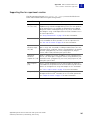
ViiA™ 7 Software command-line application . . . . . . . . . . . . . . . . . . . . . . . . . . . . . . . . . . . . . . . 184
Command-line workflows . . . . . . . . . . . . . . . . . . . . . . . . . . . . . . . . . . . . . . . . . . . . . . . . . . 184
Supporting files for experiment creation . . . . . . . . . . . . . . . . . . . . . . . . . . . . . . . . . . . . . 185
Precedence rules for experiment file generation . . . . . . . . . . . . . . . . . . . . . . . . . . . . . . 186
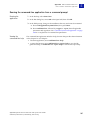
Running the command-line application from a command prompt . . . . . . . . . . . . . . . 187
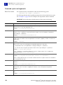
Command syntax and arguments . . . . . . . . . . . . . . . . . . . . . . . . . . . . . . . . . . . . . . . . . . . 188
Examples . . . . . . . . . . . . . . . . . . . . . . . . . . . . . . . . . . . . . . . . . . . . . . . . . . . . . . . . . . . . . . . . 190
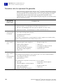
Import formats and file specifications . . . . . . . . . . . . . . . . . . . . . . . . . . . . . . . . . . . . . . . . . . . . 191
About the import file formats . . . . . . . . . . . . . . . . . . . . . . . . . . . . . . . . . . . . . . . . . . . . . . . 191
Conventions . . . . . . . . . . . . . . . . . . . . . . . . . . . . . . . . . . . . . . . . . . . . . . . . . . . . . . . . . . . . . . 191
Plate setup file format . . . . . . . . . . . . . . . . . . . . . . . . . . . . . . . . . . . . . . . . . . . . . . . . . . . . . 192
Sample file format . . . . . . . . . . . . . . . . . . . . . . . . . . . . . . . . . . . . . . . . . . . . . . . . . . . . . . . . 197
Bar code file format . . . . . . . . . . . . . . . . . . . . . . . . . . . . . . . . . . . . . . . . . . . . . . . . . . . . . . . 198
Assay information file . . . . . . . . . . . . . . . . . . . . . . . . . . . . . . . . . . . . . . . . . . . . . . . . . . . . . 198
Export formats and file specifications . . . . . . . . . . . . . . . . . . . . . . . . . . . . . . . . . . . . . . . . . . . . 199
Export formats . . . . . . . . . . . . . . . . . . . . . . . . . . . . . . . . . . . . . . . . . . . . . . . . . . . . . . . . . . . 199
ViiA™ 7 export format . . . . . . . . . . . . . . . . . . . . . . . . . . . . . . . . . . . . . . . . . . . . . . . . . . . . . . 200
7900 export format . . . . . . . . . . . . . . . . . . . . . . . . . . . . . . . . . . . . . . . . . . . . . . . . . . . . . . . . 216
RDML export format . . . . . . . . . . . . . . . . . . . . . . . . . . . . . . . . . . . . . . . . . . . . . . . . . . . . . . 222
Applied Biosystems ViiA™ 7 Real-Time PCR System User Guide:
Calibration, Maintenance, Networking, and Security
11
Contents
APPENDIX F
Safety . . . . . . . . . . . . . . . . . . . . . . . . . . . . . . . . . . . . . . . . . . . . . . . . . . . 223
Instrumentation safety . . . . . . . . . . . . . . . . . . . . . . . . . . . . . . . . . . . . . . . . . . . . . . . . . . . . . . . . . 224
Symbols on instruments . . . . . . . . . . . . . . . . . . . . . . . . . . . . . . . . . . . . . . . . . . . . . . . . . . . 224
Locations of safety labels on instruments . . . . . . . . . . . . . . . . . . . . . . . . . . . . . . . . . . . . 226
General instrument safety . . . . . . . . . . . . . . . . . . . . . . . . . . . . . . . . . . . . . . . . . . . . . . . . . 227
Physical hazard safety . . . . . . . . . . . . . . . . . . . . . . . . . . . . . . . . . . . . . . . . . . . . . . . . . . . . . 228
Electrical safety . . . . . . . . . . . . . . . . . . . . . . . . . . . . . . . . . . . . . . . . . . . . . . . . . . . . . . . . . . 228
Bar code scanner laser safety . . . . . . . . . . . . . . . . . . . . . . . . . . . . . . . . . . . . . . . . . . . . . . 229
Workstation safety . . . . . . . . . . . . . . . . . . . . . . . . . . . . . . . . . . . . . . . . . . . . . . . . . . . . . . . . 229
Safety and electromagnetic compatibility (EMC) standards . . . . . . . . . . . . . . . . . . . . . 230
Chemical safety . . . . . . . . . . . . . . . . . . . . . . . . . . . . . . . . . . . . . . . . . . . . . . . . . . . . . . . . . . . . . . .
General chemical safety . . . . . . . . . . . . . . . . . . . . . . . . . . . . . . . . . . . . . . . . . . . . . . . . . . .
SDSs . . . . . . . . . . . . . . . . . . . . . . . . . . . . . . . . . . . . . . . . . . . . . . . . . . . . . . . . . . . . . . . . . . . .
Chemical waste safety . . . . . . . . . . . . . . . . . . . . . . . . . . . . . . . . . . . . . . . . . . . . . . . . . . . . .
Biological hazard safety . . . . . . . . . . . . . . . . . . . . . . . . . . . . . . . . . . . . . . . . . . . . . . . . . . .
231
231
232
232
234
Safety alerts . . . . . . . . . . . . . . . . . . . . . . . . . . . . . . . . . . . . . . . . . . . . . . . . . . . . . . . . . . . . . . . . . .
General alerts for all chemicals . . . . . . . . . . . . . . . . . . . . . . . . . . . . . . . . . . . . . . . . . . . .
General alerts for instrumentation . . . . . . . . . . . . . . . . . . . . . . . . . . . . . . . . . . . . . . . . . .
Specific alerts for instrumentation . . . . . . . . . . . . . . . . . . . . . . . . . . . . . . . . . . . . . . . . . .
235
235
235
235
Documentation and Support . . . . . . . . . . . . . . . . . . . . . . . . . . . . . . . 237
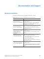
Related documentation . . . . . . . . . . . . . . . . . . . . . . . . . . . . . . . . . . . . . . . . . . . . . . . . . . . . . . . . 237
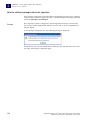
Obtaining information from the Help system . . . . . . . . . . . . . . . . . . . . . . . . . . . . . . . . . . . . . . 239
Obtaining support . . . . . . . . . . . . . . . . . . . . . . . . . . . . . . . . . . . . . . . . . . . . . . . . . . . . . . . . . . . . . 240
Glossary . . . . . . . . . . . . . . . . . . . . . . . . . . . . . . . . . . . . . . . . . . . . . . . . . 241
Index . . . . . . . . . . . . . . . . . . . . . . . . . . . . . . . . . . . . . . . . . . . . . . . . . . . . 253
12
Applied Biosystems ViiA™ 7 Real-Time PCR System User Guide:
Calibration, Maintenance, Networking, and Security
About This Guide
Purpose
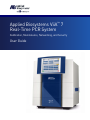
The Applied Biosystems ViiA™ 7 Real-Time PCR System User Guide provides
reference information for the ViiA™ 7 Instrument and describes how to prepare,
maintain, and troubleshoot the system.
Audience
This user guide is written for laboratory staff who operate and maintain the ViiA™ 7
System.
Assumptions
This guide assumes that your ViiA™ 7 System has been installed by an Applied
Biosystems service representative.
This guide also assumes that you have:
• Familiarity with Microsoft® Windows® operating system.
• Knowledge of techniques for handling and preparing DNA samples for PCR.
• A general understanding of data storage, file transfers, and copying and pasting.
Applied Biosystems ViiA™ 7 Real-Time PCR System User Guide:
Calibration, Maintenance, Networking, and Security
13
About This Guide
Safety information
Safety information
Note: For general safety information, see this section and Appendix F, “Safety” on
page 223. When a hazard symbol and hazard type appear by a chemical name or
instrument hazard, see the “Safety” Appendix for the complete alert on the chemical or
instrument.
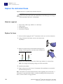
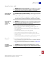
Safety alert words
Four safety alert words appear in Applied Biosystems user documentation at points in
the document where you need to be aware of relevant hazards. Each alert word—
IMPORTANT, CAUTION, WARNING, DANGER—implies a particular level of
observation or action, as defined below:
IMPORTANT! – Indicates information that is necessary for proper instrument
operation, accurate chemistry kit use, or safe use of a chemical.
CAUTION! – Indicates a potentially hazardous situation that, if not avoided,
may result in minor or moderate injury. It may also be used to alert against
unsafe practices.
WARNING! – Indicates a potentially hazardous situation that, if not avoided,
could result in death or serious injury.
DANGER! – Indicates an imminently hazardous situation that, if not avoided,
will result in death or serious injury. This signal word is to be limited to the most
extreme situations.
Except for IMPORTANTs, each safety alert word in an Applied Biosystems document
appears with an open triangle figure that contains a hazard symbol. These hazard
symbols are identical to the hazard symbols that are affixed to Applied Biosystems instruments
(see “Safety symbols” on page 224).
SDSs
The SDSs for any chemicals supplied by Applied Biosystems or Ambion are available
to you free 24 hours a day. For instructions on obtaining SDSs, see “SDSs” on page 232.
IMPORTANT! For the SDSs of chemicals not distributed by Applied Biosystems or
Ambion contact the chemical manufacturer.
14
Applied Biosystems ViiA™ 7 Real-Time PCR System User Guide:
Calibration, Maintenance, Networking, and Security
About This Guide
Safety information
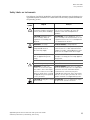
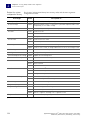
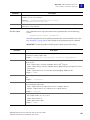
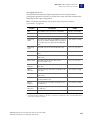
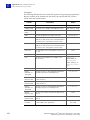
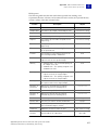
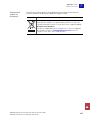
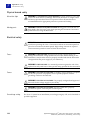
Safety labels on instruments
The following CAUTION, WARNING, and DANGER statements may be displayed on
Applied Biosystems instruments in combination with the safety symbols described in
the preceding section.
Hazard
symbol
English
Français
CAUTION! Hazardous
chemicals. Read the Safety Data
Sheets (SDSs) before handling.
ATTENTION! Produits chimiques dangereux.
Lire les fiches techniques de sûreté de
matériels avant toute manipulation de
produits.
CAUTION! Hazardous waste.
Refer to SDS(s) and local
regulations for handling and
disposal.
ATTENTION! Déchets dangereux. Lire les
fiches techniques de sûreté de matériels et la
régulation locale associées à la manipulation
et l’élimination des déchets.
WARNING! Hot lamp.
AVERTISSEMENT! Lampe brûlante.
WARNING! Hot. Do not remove
lamp until 15 min after
disconnecting supply.
AVERTISSEMENT! Lampe brûlante, après
avoir déconnecté le câble d’alimentation de
l’appareil, attendre environ 15 minutes avant
d’effectuer un remplacement de la lampe.
WARNING! Hot. Replace lamp
with an Applied Biosystems
lamp.
AVERTISSEMENT! Composants brûlants.
Remplacer la lampe par une lampe Applied
Biosystems.
CAUTION! Hot surface.
ATTENTION! Surface brûlante.
DANGER! High voltage.
DANGER! Haute tension.
WARNING! To reduce the
chance of electrical shock, do
not remove covers that require
tool access. No user-serviceable
parts are inside. Refer servicing
to Applied Biosystems qualified
service personnel.
AVERTISSEMENT! Pour éviter les risques
d’électrocution, ne pas retirer les capots dont
l’ouverture nécessite l’utilisation d’outils.
L’instrument ne contient aucune pièce
réparable par l’utilisateur. Toute intervention
doit être effectuée par le personnel de service
qualifié venant de chez Applied Biosystems.
CAUTION! Moving parts. Crush/
pinch hazard.
ATTENTION! Pièces en mouvement, risque
de pincement et/ou d’écrasement.
Applied Biosystems ViiA™ 7 Real-Time PCR System User Guide:
Calibration, Maintenance, Networking, and Security
15
About This Guide
Safety information
16
Applied Biosystems ViiA™ 7 Real-Time PCR System User Guide:
Calibration, Maintenance, Networking, and Security
CHAPTER 1
Getting Started
1
This chapter covers:
■
About the ViiA™ 7 System . . . . . . . . . . . . . . . . . . . . . . . . . . . . . . . . . . . . . . . . . . . . . 18
■
Specifications and layout. . . . . . . . . . . . . . . . . . . . . . . . . . . . . . . . . . . . . . . . . . . . . . . 20
■
ViiA™ 7 System hardware . . . . . . . . . . . . . . . . . . . . . . . . . . . . . . . . . . . . . . . . . . . . . 24
■
ViiA™ 7 System software . . . . . . . . . . . . . . . . . . . . . . . . . . . . . . . . . . . . . . . . . . . . . . 30
■
Using this guide . . . . . . . . . . . . . . . . . . . . . . . . . . . . . . . . . . . . . . . . . . . . . . . . . . . . . . 32
Access the Help system by pressing F1, by clicking
in the toolbar of the ViiA™ 7
Software window, or by selecting HelpContents and Index.
Applied Biosystems ViiA™ 7 Real-Time PCR System User Guide:
Calibration, Maintenance, Networking, and Security
17
1
Chapter 1 Getting Started
About the ViiA™ 7 System
About the ViiA™ 7 System
The Applied Biosystems ViiA™ 7 Real-Time PCR System uses fluorescent-based
polymerase chain reaction (PCR) reagents to provide:
• Quantitative research detection of target nucleic acid sequences (targets) using
real-time analysis.
• Qualitative research detection of targets using post-PCR (endpoint) analysis.
• Qualitative analysis of the PCR product (achieved by melt curve analysis that
occurs post-PCR).
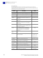
About data collection
The Applied Biosystems ViiA™ 7 Real-Time PCR System collects raw fluorescence
data at different points during a PCR, depending on the type of run that the ViiA™ 7
Instrument performs:
Run type
Real-time
runs
Data collection point
Standard curve
Relative standard curve
The ViiA™ 7 Instrument collects data following each
extension step of the PCR.
Comparative CT (ΔΔCT)
Melting curve
Post-PCR
(endpoint)
runs
Genotyping
The ViiA™ 7 Instrument collects data:
1. Before the PCR. (For presence/absence
experiments, data collection before the PCR is
optional, but recommended.)
Presence/absence
2. (Optional) During the PCR. The ViiA™ 7
Instrument can collect data during the run (realtime); collecting data during the run can be
helpful for troubleshooting.
3. After the PCR.
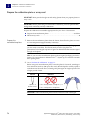
Regardless of the run type, a data collection point, or read, on the Applied Biosystems
ViiA™ 7 Real-Time PCR System consists of three phases:
1. Excitation – The ViiA™ 7 Instrument illuminates all wells of the reaction plate
within the instrument, exciting the fluorophores in each reaction.
18
Applied Biosystems ViiA™ 7 Real-Time PCR System User Guide:
Calibration, Maintenance, Networking, and Security
Chapter 1 Getting Started
About the ViiA™ 7 System
1
2. Emission – The ViiA™ 7 Instrument optics collect the residual fluorescence
emitted from the wells of the reaction plate. The resulting image collected by the
device consists only of light that corresponds to the range of emission
wavelengths.
3. Collection – The ViiA™ 7 Instrument assembles a digital representation of the
residual fluorescence collected over a fixed time interval. The ViiA™ 7 Software
stores the raw fluorescent image for analysis.
After a run, the ViiA™ 7 Software uses calibration data (ROI, background, uniformity,
dye, and normalization) to determine the location and intensity of the fluorescent
signals in each read, the dye associated with each fluorescent signal, and the
significance of the signal.
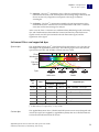
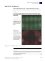
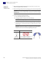
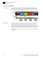
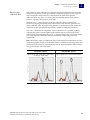
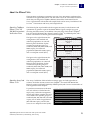
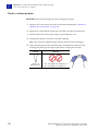
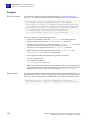
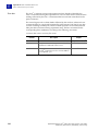
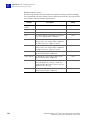
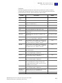
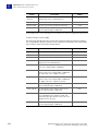
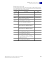
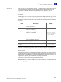
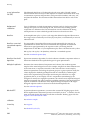
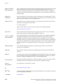
Instrument filters and supported dyes
System dyes
The Applied Biosystems ViiA™ 7 Real-Time PCR System features a six-color filter set
that supports all Applied Biosystems dyes. The following figure shows the emission
spectrum for each dye, and the filter at which each dye is read.
Filters
Wavelength
(nm)
x1-m1 x2-m2 x3-m3 x4-m4 x5-m5 x6-m6
500
600
700
Emission
Spectra
Dyes
~520 nm
~550 nm
~580 nm
~610 nm
FAM
SYBR Green
VIC
NED
TAMRA
ROX
Filter wavelength (nm)‡
Filter
set
Color
x1-m1
Supported dyes
Excitation
Emission
Blue
470±15
520±15
FAM™ and SYBR® Green dyes
x2-m2
Green
520±10
558±12
VIC®, JOE™, TET™, and HEX™ dyes
x3-m3
Yellow
549.5±10
586.5±10
x4-m4
Orange
580±10
623±14
ROX™ dye
x5-m5
Red
640±10
682±14
LIZ™ dye
x6-m6
Deep red
662±10
711±12
None§
NED™ and TAMRA™ dyes
‡ The central wavelengths are the optimized wavelengths.
§ No Applied Biosystems supported dye currently available.
Custom dyes
The Applied Biosystems ViiA™ 7 Real-Time PCR System can run assays designed with
custom dyes (dyes not supplied by Applied Biosystems) that are excited between 455
to 672 nm and read between 505 to 723 nm.
Applied Biosystems ViiA™ 7 Real-Time PCR System User Guide:
Calibration, Maintenance, Networking, and Security
19
1
Chapter 1 Getting Started
Specifications and layout
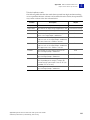
Specifications and layout
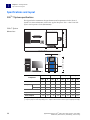
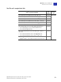
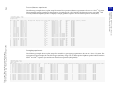
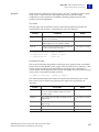
ViiA™ 7 System specifications
The figures below summarize the specifications and requirements for the ViiA™ 7
System. For more information, refer to the Applied Biosystems ViiA™ 7 Real-Time PCR
System Site Preparation Guide (PN 4445302).
ViiA™ 7 System
dimensions
15.24 cm (6 in.)
78.8 cm (31 in.)
63.5 cm (25 in.)
53.3 cm (21 in.)
162.56 cm (64 in.)
15.24 cm (6 in.)
64.5 cm (25.4 in.)
Width
Depth
Height
Weight
Component
cm
in
cm
in
cm
in
kg
53.3
21.0
63.5
25.0
64.5
25.4
60.7
133.5
Laptop
35.8
14.1
25.7
10.1
35.8
14.1
2.6
5.7
Desktop
18.7
7.3
44.5
17.5
41.0
16.1
10.9
24.0
Monitor
44.7
17.5
19.3
7.6
36.6
14.4
6.9
15.2
Keyboard
44.7
17.5
15.25
6.0
5.0
2.0
0.1
0.2
Total footprint
233
91.7
86
33.8
79.7
31.4
77.9
171.5
Instrument‡
Computer§
lbs
‡ Weight varies depending on the sample block installed.
§ Computer properties differ depending on the computer ordered with the ViiA™ 7 System (laptop or desktop).
20
Applied Biosystems ViiA™ 7 Real-Time PCR System User Guide:
Calibration, Maintenance, Networking, and Security
Chapter 1 Getting Started
1
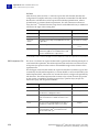
Specifications and layout
ViiA™ 7 System with
Twister® II Robot
dimensions
15.24 cm (6 in.)
81.28 cm (32 in.)
63.5 cm (25 in.)
53.3 cm (21 in.)
213.36 cm (84 in.)
97.0 cm (38 in.)
Width
Depth
Height
Weight
Component
cm
in
cm
in
cm
in
kg
53.3
21.0
63.5
25.0
64.5
25.4
60.7
133.5
Laptop
35.8
14.1
25.7
10.1
35.8
14.1
2.6
5.7
Desktop
18.7
7.3
44.5
17.5
41.0
16.1
10.9
24.0
Monitor
44.7
17.5
19.3
7.6
36.6
14.4
6.9
15.2
Keyboard
44.7
17.5
15.25
6.0
5.0
2.0
0.1
0.2
Twister® II Robot#
53.3
21.0
77.0
28.0
97.0
38.0
31.8
70.0
311.0
122.2
86.0
33.9
97.0
38.0
109.7
241.5
Instrument‡
Computer§
Total footprint
lbs
‡ Weight varies depending on the sample block installed.
§ Computer specification differs depending on the computer ordered with the ViiA™ 7 System (laptop or desktop).
# The Applied Biosystems Twister® II Robot is an optional component of the ViiA™ 7 System.
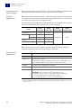
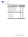
Required clearance
The ViiA™ 7 Instrument requires the following additional clearances:
• Clearance on all sides – At least 15.2 cm (6 in) of clearance for ventilation, service
access, and cable routing.
• Vertical clearance – At least 30.5 cm (12 in) of unobstructed vertical clearance
above the ViiA™ 7 Instrument to allow removal of the cover during service.
Applied Biosystems ViiA™ 7 Real-Time PCR System User Guide:
Calibration, Maintenance, Networking, and Security
21
1
Chapter 1 Getting Started
Specifications and layout
Instrument hot-air
exhaust venting
The maximum thermal output of the ViiA™ 7 Instrument is 2731BTU/hr (800W) vented
directly into the room air from the hot-air waste port on the rear panel.
Electrical
requirements
Note: We recommend placing the ViiA™ 7 Instrument and computer power receptacle
on an electrical circuit that is not shared with electrically noisy devices or devices that
can cause power surges, such as refrigeration units.
The following table provides electrical specifications for the instrument and associated
devices. For all indicated input voltages, a 15 A circuit is required.
Rated
current (A)
Rated
power (VA)
12.5
950
Desktop
2.1
125
Laptop
1.5
90
Monitor
1.5
65
Twister® II Robot‡
2.5
150
Device
Instrument
Computer
Rated
voltage (VAC)
Rated
frequency (Hz)
100-240±10%
50/60
‡ The Twister® II Robot is an optional component of the ViiA™ 7 System.
Note: The instrument, monitor, desktop computer, Twister® II Robot, and laptop
computer self-adjust for 100v-240v input voltages of 50/60 Hz.
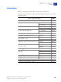
Environmental
requirements
Requirement
Description
Altitude
Less than 2000 m (6500 ft) above sea level
Temperature
15 to 30 °C (59 to 86 °F)
Do not place the ViiA™ 7 Instrument next to heaters, cooling ducts, or in
direct sunlight. Temperature fluctuations can affect performance.
Humidity
20 to 80% relative humidity, noncondensing
Pollution
Pollution Degree rating of 2‡
Location
For indoor use only
IMPORTANT! Do not locate the ViiA™ 7 Instrument next to:
• Vibration sources, such as a centrifuge, pump, or compressor.
Excessive vibration affects instrument performance.
• Electrically noisy devices, such as a refrigeration unit.
‡ The ViiA™ 7 Instrument can be used in an environment that contains nonconductive pollutants only (dust
particles or wood chips). Typical environments with a Pollution Degree 2 rating are laboratories, sales, and
commercial areas.
22
Applied Biosystems ViiA™ 7 Real-Time PCR System User Guide:
Calibration, Maintenance, Networking, and Security
Chapter 1 Getting Started
Specifications and layout
1
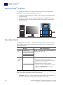
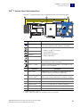
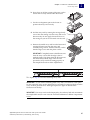
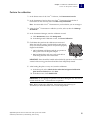
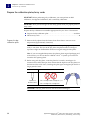
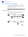
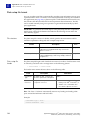
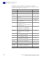
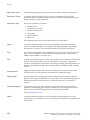
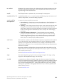
ViiA™ 7 System layout and connections
The ViiA™ 7 System consists of the components shown in the following figure.
A
A
A
G
B
C
D
E
D
F
Component
Description
ViiA™ 7 Instrument
Performs fluorescence research detection and data
collection of experiment and calibration consumables.
Computer
Run the ViiA™ 7 Software that is used to:
• Calibrate the ViiA™ 7 Instrument.
Monitor
Keyboard
Mouse
• Set up experiments.
• (Optional) Run experiments.
• Analyze experiments.
Bar code reader
Scans the bar codes of consumables before and after they
are loaded into the ViiA™ 7 Instrument.
Twister® II Robot
Automates loading and unloading of consumables to and
from the ViiA™ 7 Instrument.
Connection
Description
A
Power cables
Supply power to the computer, the Applied Biosystems
Twister® II Robot, and the ViiA™ 7 Instrument.§
B
LAN connection or
Ethernet cable‡
Connects the ViiA™ 7 Instrument (Ethernet 1 port) to the
Ethernet port on the network interface card in the computer.
C
DVI cable
Connects the monitor to the computer (DVI port).
D
Bar code reader cable
Connects the bar code reader to the computer (USB port).
E
Keyboard cable
Connects the keyboard to the computer (USB port).
F
Mouse cable
Connects the mouse to the computer (USB port).
G
Serial cable
Connects the Twister® II Robot to the computer (serial port).
‡ Supplied with the ViiA™ 7 System.
§ Supplies 115/230 V depending on the geographic location of the installation.
Applied Biosystems ViiA™ 7 Real-Time PCR System User Guide:
Calibration, Maintenance, Networking, and Security
23
1
Chapter 1 Getting Started
ViiA™ 7 System hardware
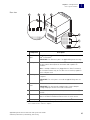
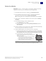
ViiA™ 7 System hardware
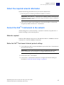
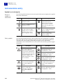
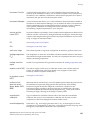
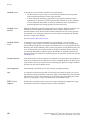
Instrument components
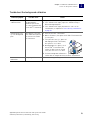
The ViiA™ 7 System consists of the components shown in the following figures.
Front view
B
D
A
G
H
C
I
E
Component
A
USB ports
F
Description
Provide USB communication with the ViiA™ 7 Instrument. Can be used
to transfer data to and from the instrument and to update the firmware.
Note: If multiple USB drives are plugged into the ViiA™ 7 Instrument,
the instrument mounts only the first drive that is installed, regardless
of the USB port used.
24
B
Instrument
touchscreen
Provides access to the ViiA™ 7 Instrument functions. Can be used to run
experiments, transfer data, and operate the instrument functions
without the use of the computer.
C
Access door
Provides access to the ViiA™ 7 Instrument lamp, the heated cover, and
the sample block.
D
Lamp
Illuminates the reaction plate or array card during a run.
E
Heated cover
Covers the plate or array card during a run to prevent condensation and
leakage through the consumable cover.
F
Sample block
Heats the plate or array card during a run.
G
Side door
Opens to allow extension of the tray arm.
H
Plate adapter
Secures plates or array cards to the tray arm.
I
Tray arm
Conveys plates or array cards to and from the sample block in the
interior of the ViiA™ 7 Instrument.
Applied Biosystems ViiA™ 7 Real-Time PCR System User Guide:
Calibration, Maintenance, Networking, and Security
Chapter 1 Getting Started
1
ViiA™ 7 System hardware
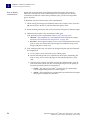
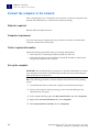
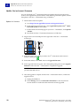
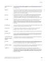
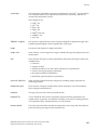
Rear view
A
B
Ethernet
1
Ethernet
2
USB
1
C
USB
2
RS232
D
Eth
ern
et
1
Eth
ern
et
2
US
B
1
US
B
2
RS
23
2
E
PWR
PW
R
F1
F1
F2
F
F2
G
Component
A
Ethernet 1
port
Description
An RJ45 port that provides Ethernet (Gigabit) communication with the
ViiA™ 7 Instrument.‡
IMPORTANT! The Ethernet 2 port is for Applied Biosystems use only.
B
USB ports
Provide USB communication with the ViiA™ 7 Instrument. They can be
used to transfer data to/from the instrument and to update the
firmware.
Note: If multiple USB drives are plugged into the ViiA™ 7 Instrument,
the instrument mounts only the first drive that is installed, regardless
of the USB port used.
C
RS232 port
Provides serial communication between the ViiA™ 7 Instrument and the
computer.
IMPORTANT! The serial port is reserved for Applied Biosystems use
only.
Instrument
fans
Cool the interior of the ViiA™ 7 Instrument.
E
On/Off switch
Power switch for the ViiA™ 7 Instrument, where the states are on ( | ) or
off ( O ).
F
Fuse cover
Dual 12.5A, Time-Lag T, 250VAC, 5 × 20-mm electrical fuses that
protect the ViiA™ 7 Instrument from excessive electrical current.
G
Power port
The 100-240VAC port that provides power to the ViiA™ 7 Instrument.
D
IMPORTANT! The fans must be unobstructed to ensure adequate
cooling and proper function of the ViiA™ 7 Instrument.
‡ Use the Ethernet cable supplied with the ViiA™ 7 System to connect the ViiA™ 7 Instrument (Ethernet 1 port)
to the network interface card in the computer.
Applied Biosystems ViiA™ 7 Real-Time PCR System User Guide:
Calibration, Maintenance, Networking, and Security
25
1
Chapter 1 Getting Started
ViiA™ 7 System hardware
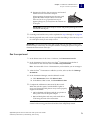
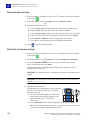
Bar code readers
The Applied Biosystems ViiA™ 7 Real-Time PCR System can include two bar code
readers for data entry and plate recognition:
• A hand-held bar code reader for scanning plates manually.
• A fixed-position bar code reader for automatically scanning plates as they are
loaded into the instrument (available only with the Twister® II Robot).
Both bar code readers use 670 nm Class II lasers to scan plates, and both readers are
capable of reading Code 128 (alphanumeric), which supports 128 ASCII character bar
codes. The bar code readers are optional and available depending on the system
configuration.
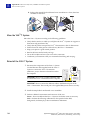
About the hand-held
bar code reader
WARNING! LASER HAZARD. Exposure to direct or reflected laser light can
burn the retina and leave permanent blind spots. Never look into the laser beam.
Remove jewelry and anything else that can reflect the beam into your eyes.
Protect others from exposure to the beam.
The optional hand-held bar code reader functions as an extension of the keyboard that
you can use to scan bar codes into the ViiA™ 7 Software.
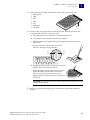
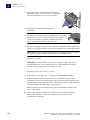
To scan a bar code using the hand-held bar code reader:
1. Select the field in the ViiA™ 7 Software where you want to enter the bar code.
2. Hold the hand-held bar code reader 20 to 30 cm away from a plate and aim at the
center of the bar code, then press the trigger. Slowly move the scanning beam
across the bar code until the reader emits a high-pitched tone.
When the reader scans a bar code, it automatically:
• Transmits the alphanumeric equivalent of the bar code to the ViiA™ 7 Software.
The software enters the bar code text wherever the cursor is active.
• Transmits a carriage-return character (the equivalent of pressing the Enter key).
For more information on the hand-held bar code reader, see the bar code reader user
documentation shipped with the ViiA™ 7 System.
26
Applied Biosystems ViiA™ 7 Real-Time PCR System User Guide:
Calibration, Maintenance, Networking, and Security
Chapter 1 Getting Started
ViiA™ 7 System hardware
1
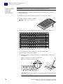
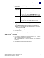
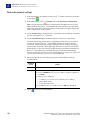
Twister® II Robot components
The ViiA™ 7 System supports the use of the Applied Biosystems Twister® II Robot, an
optional ViiA™ 7 System accessory that consists of the components shown below.
Note: See the Applied Biosystems ViiA™ 7 Real-Time PCR System Robotics Guide
(PN 4442663) for information on operating, calibrating, maintaining and integrating
the Twister® II Robot.
Front view
A
B
C
D
H
E
F
I
G
Component
Description
A
Reach axis
Moves the grip horizontally 11.25 in (28.5 cm) to 19.75 in (50.1 cm) from
the center of the robot post.
B
Wrist
mechanism
Rotates materials to either the portrait or landscape positions, where
the range of motion is ±135° (270° total).
C
Grip
Consists of two sets of fingers that grip the consumable. The fingers
close to grasp a consumable and open to release it.
D
Robot tower/
vertical axis
Moves the arm up and down 21.5 in (54.6 cm), from 6.5 in (16.5 cm) to
28 in (71.1 cm) above the table.
E
Rotary axis
Rotates the arm 340° around the base of the Twister® II Robot.
Mechanical stops prevent continuous rotation.
F
Bar code
reader
Scans the bar codes of consumables as they are loaded into the ViiA™ 7
Instrument.
G
Base cover
Removable cover that contains four access bolts, which secure the
Twister® II Robot to the Sciclone ALH 3000 base.
H
Racks
Provide storage for PCR consumables before and after they are run by
the ViiA™ 7 Instrument (one of three shown).
I
Power LED
When lit, indicates the Twister® II Robot is powered on.
Applied Biosystems ViiA™ 7 Real-Time PCR System User Guide:
Calibration, Maintenance, Networking, and Security
27
1
Chapter 1 Getting Started
ViiA™ 7 System hardware
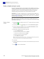
Rear view
A
B
C
D
Rack parts and
functions
Component
Description
A
On/Off switch
Power switch for the Twister® II Robot, where the states are on ( | ) or
off ( O ).
B
Power port
100–240V port that provides power to the Twister® II Robot.
C
RS232 port
Provides serial communication with the computer.
D
Fuse cover
Two T1.6A 250VAC, 5 × 20-mm electrical fuses that protect the Twister®
II Robot from excessive electrical current.
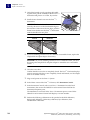
Racks are removable aluminum frames used as input and output locations for PCR
consumables. Rack positions are numbered counter-clockwise, with position 1 closest
to the front of the Twister® II Robot (see below). Each rack is labeled for a specific
position and cannot be exchanged with the other racks.
A
3
A
A
2
1
B
Component
Description
A
Handles
For connecting or disconnecting racks from the pod.
B
Rack locator
notch
Locks the rack onto the pod in the correct position.
Note: Do not drop the racks. If the rack is bent, the Twister® II Robot cannot properly
place the consumables.
28
Applied Biosystems ViiA™ 7 Real-Time PCR System User Guide:
Calibration, Maintenance, Networking, and Security
Chapter 1 Getting Started
ViiA™ 7 System hardware
1
Electrical protective devices
We recommend several protective devices to protect the ViiA™ 7 System in
environments with large voltage and power fluctuations.
Power line regulator
We recommend the use of a 1.5-kVA power line regulator in areas where the supplied
power fluctuates in excess of ±10% of the normal voltage. Power fluctuations can
adversely affect the function of the ViiA™ 7 System.
Note: A power line regulator monitors the input current and adjusts the power
supplied to the ViiA™ 7 System or computer. It does not protect against a power surge
or failure.
Uninterruptible
power supply (UPS)
We recommend the use of a 1.5-kVA uninterruptible power supply (UPS), especially in
areas prone to power failure. Power failures and other events that abruptly terminate
the function of the ViiA™ 7 System can corrupt data and possibly damage the
computer or the instrument.
IMPORTANT! UPSs provide power for a limited time. They are meant to delay the
effects of a power outage, not to serve as replacement power sources. In the event of a
power loss, power off the instrument and the computer, unless you expect to regain
power within the battery life of the UPS.
Surge protector
We recommend the use of a 10-kVA surge protector (line conditioner) in areas with
frequent electrical storms or near devices that are electrically noisy, such as
refrigerators, air conditioners, or centrifuges. Short-duration, high-voltage power
fluctuations can abruptly terminate the function of, and thereby damage the
components of, the computer and the ViiA™ 7 Instrument.
Note: A dedicated line and ground between the ViiA™ 7 System/computer and the
building’s main electrical service can also prevent problems caused by power
fluctuations.
Applied Biosystems ViiA™ 7 Real-Time PCR System User Guide:
Calibration, Maintenance, Networking, and Security
29
1
Chapter 1 Getting Started
ViiA™ 7 System software
ViiA™ 7 System software
The ViiA™ 7 System includes a suite of software applications that can be used to
calibrate, run, automate, and integrate the ViiA™ 7 System into a laboratory workflow.
The basic installation of the ViiA™ 7 Software contains the components described
below; however, additional software may be available for the ViiA™ 7 System. Visit the
ViiA™ 7 System website for a complete list of compatible software:
www.appliedbiosystems.com/viia7/
Note: Visit the ViiA™ 7 System website for updates and patches for the ViiA™ 7
Software and ViiA™ 7 Instrument Firmware.
Computer requirements
The requirements for the computer used to operate the ViiA™ 7 Instrument can vary
depending on the version of the ViiA™ 7 Software that you are running. To determine
the computer requirements for your ViiA™ 7 System, check the ViiA™ 7 Software
release notes at the following location:
D:\AppliedBiosystems\ViiA7 Software\release-notes.html
Software installation
The default installation of the ViiA™ 7 System partitions the computer hard drive to
create the logical drives shown below.
Drive
Software
Description
C
Microsoft® Windows® OS‡
Operating system files.
D
ViiA™ 7 Software
Used to calibrate and perform experiments on the
ViiA™ 7 Instrument.
ViiA™ 7 System Commandline Utility
Used to automate the creation of new experiments
and the export of existing experiments.
Twister® II Robot Software
Controls the Twister® II Robot, stores all of the
taught positions for the robot, and includes the VBA
code required to operate the Twister® II Robot with
the automation control software.
‡ We recommend that you do not install programs to the C drive.
30
Applied Biosystems ViiA™ 7 Real-Time PCR System User Guide:
Calibration, Maintenance, Networking, and Security
Chapter 1 Getting Started
ViiA™ 7 System software
1
Third-party software
Before you install third-party software to the computer running the ViiA™ 7 Software,
confirm that the software will not:
• Restrict Ethernet communication
• Interfere with ViiA™ 7 Software operation (see below)
To confirm that third-party software does not interfere with the ViiA™ 7 Software:
1. Install the software to the computer that contains the ViiA™ 7 Software.
2. Perform several test experiments using “dummy” plates (plates that do not
contain reagents).
Note: The goal of the test experiments is to run plates under conditions that
match normal instrument operation. Therefore, the characteristics of the test
experiments (plate layout and run method) must closely resemble your actual
experiments.
3. Confirm that the ViiA™ 7 System performs each test experiment without
producing errors.
If the ViiA™ 7 System performs the tests successfully, perform experiments
normally. If the ViiA™ 7 System encounters errors during the test runs, the
software may not be compatible with the ViiA™ 7 Software.
Applied Biosystems ViiA™ 7 Real-Time PCR System User Guide:
Calibration, Maintenance, Networking, and Security
31
1
Chapter 1 Getting Started
Using this guide
Using this guide
You can use this guide to calibrate, service, network, and administrate the Applied
Biosystems ViiA™ 7 Real-Time PCR System.
This user guide contains the following information:
• Chapter 2, “Calibration and Maintenance” – Describes how to perform regular
maintenance of the ViiA™ 7 System, including calibrating the ViiA™ 7 Instrument
and verifying instrument performance.
• Chapter 3, “Networking” – Describes how to install the ViiA™ 7 System to a local
area network for remote monitoring and control.
• Chapter 4, “Security, Audit, and Electronic Signature” – Describes how to
configure the security, audit, and e-signature functions of the ViiA™ 7 Software.
• Chapter 5, “Service” – Describes how to replace the user-serviceable parts of the
ViiA™ 7 Instrument and resolve infrequent problems that can occur during
normal use.
• Appendix A, “Manual Instrument Operation” – Describes how to operate the
ViiA™ 7 Instrument manually using the touchscreen interface.
• Appendix B, “Power On or Off, Store, and Move the ViiA™ 7 System” – Describes
how to store, move, and reinstall the components of the system.
• Appendix C, “Creating Custom Calibration Plates and Array Cards” – Describes
how to create a background plate in the event that one is unavailable, and how to
create a dye plate that can be used to calibrate the system for a dye not
manufactured by Applied Biosystems.
• Appendix D, “Parts and Materials” – Describes how to order parts, accessories,
and consumables for the ViiA™ 7 System.
• Appendix E, “ViiA™ 7 Software Reference” – Describes how to use the ViiA™ 7
Software command line application, and provides specifications for files that the
ViiA™ 7 Software imports, exports, and stores.
32
Applied Biosystems ViiA™ 7 Real-Time PCR System User Guide:
Calibration, Maintenance, Networking, and Security
CHAPTER 2
Calibration and Maintenance
2
This chapter covers:
■
Calibrate and maintain the ViiA™ 7 System . . . . . . . . . . . . . . . . . . . . . . . . . . . . . . 34
■
About the consumables . . . . . . . . . . . . . . . . . . . . . . . . . . . . . . . . . . . . . . . . . . . . . . . . 35
■
Perform regular data maintenance . . . . . . . . . . . . . . . . . . . . . . . . . . . . . . . . . . . . . . 37
■
Fill the array cards . . . . . . . . . . . . . . . . . . . . . . . . . . . . . . . . . . . . . . . . . . . . . . . . . . . . 38
■
Perform the ROI calibration . . . . . . . . . . . . . . . . . . . . . . . . . . . . . . . . . . . . . . . . . . . . 42
■
Perform the background calibration . . . . . . . . . . . . . . . . . . . . . . . . . . . . . . . . . . . . . 48
■
Perform the uniformity calibration . . . . . . . . . . . . . . . . . . . . . . . . . . . . . . . . . . . . . . 55
■
Perform the dye calibration. . . . . . . . . . . . . . . . . . . . . . . . . . . . . . . . . . . . . . . . . . . . . 60
■
Perform the normalization calibration . . . . . . . . . . . . . . . . . . . . . . . . . . . . . . . . . . . 69
■
Verify the instrument performance . . . . . . . . . . . . . . . . . . . . . . . . . . . . . . . . . . . . . . 74
Access the Help system by pressing F1, by clicking
in the toolbar of the ViiA™ 7
Software window, or by selecting HelpContents and Index.
Applied Biosystems ViiA™ 7 Real-Time PCR System User Guide:
Calibration, Maintenance, Networking, and Security
33
2
Chapter 2 Calibration and Maintenance
Calibrate and maintain the ViiA™ 7 System
Calibrate and maintain the ViiA™ 7 System
The Applied Biosystems ViiA™ 7 Real-Time PCR System requires regular calibration
and maintenance for proper operation. This chapter contains the procedures that you
must perform on a regular basis to ensure optimal instrument performance.
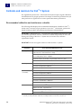
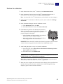
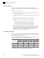
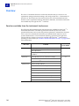
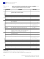
Recommended calibration and maintenance schedule
The following table displays the recommended maintenance schedule for ViiA™ 7
System users. To ensure proper operation of your ViiA™ 7 Instrument, perform the
regular weekly, monthly, and semiannual maintenance indicated below.
IMPORTANT! Calibrate the ViiA™ 7 System at the same ambient temperature at which
you will run experiments. Extreme variations in ambient temperature can affect the
heating and cooling of the ViiA™ 7 System and, in extreme cases, influence
experimental results.
IMPORTANT! Do not use organic solvents to clean the ViiA™ 7 System.
Frequency
Weekly
User-performed maintenance task
Check the computer disk space. If necessary, archive or back up your
experiment files and instrument settings.
Power off the computer that controls the ViiA™ 7 System, then after
30 seconds, power on the computer.
Clean the surface of the ViiA™ 7 System with a lint-free cloth.
Perform a ViiA™ 7 Instrument self test.
Monthly
Check the lamp status. If necessary, replace the lamp.
Perform a background calibration.‡
Run disk cleanup and disk defragmentation.
Semi-annually
(6 months)
Perform a regions of interest (ROI) calibration.
Perform a background calibration.
Perform a uniformity calibration.
Perform a dye calibration.
Perform a normalization calibration.
Perform an instrument verification run.
As needed
Decontaminate the ViiA™ 7 System.
Replace the ViiA™ 7 System fuses.
Update the Windows operating system.
Update the ViiA™ 7 Software and firmware.
‡ You can perform a background calibration to check for contamination. If any parts of the optics are replaced
or moved, you must perform all calibrations, including an RNase P instrument verification run.
34
Applied Biosystems ViiA™ 7 Real-Time PCR System User Guide:
Calibration, Maintenance, Networking, and Security
Chapter 2 Calibration and Maintenance
2
About the consumables
About the consumables
The ViiA™ 7 System uses a series of specialized consumables for calibration. The
calibration plates and array cards can be ordered from the Applied Biosystems
website. Use the consumables appropriate for the sample block of your ViiA™ 7
System.
Sample
block
Consumable
96-well
plate,
0.2 mL
• MicroAmp® Optical 8-Cap
Strip
Reaction
volume
50 µL
• MicroAmp® 8-Tube Strips
(0.2-mL)
• MicroAmp® Reaction Tubes
without Caps (0.2-mL)
• MicroAmp® 96-Well Tray/
Retainer Set
• MicroAmp® Optical
Adhesive Film
50 µL
• MicroAmp® Optical 96-Well
Reaction Plate with Bar
Code
• MicroAmp® Optical
Adhesive Film
96-well
plate,
0.1 mL
384-well
plate
50 µL
• MicroAmp® Optical 96-Well
Fast Reaction Plate with Bar
Code
Notched corner
• MicroAmp® Optical
Adhesive Film
20 µL
• MicroAmp® Optical 384Well Reaction Plate with Bar
Code
Array card
Applied Biosystems ViiA™ 7 Real-Time PCR System User Guide:
Calibration, Maintenance, Networking, and Security
Applied Biosystems Array Card
1 µL
35
2
Chapter 2 Calibration and Maintenance
About the consumables
Observe the following guidelines when using tubes, plates, or array cards:
• Store the calibration plates or array cards in a dark place until you are ready to
use them. The fluorescent dyes in the wells of calibration consumables are
photosensitive. Prolonged exposure to light can diminish the fluorescence of the
dyes.
• Do not allow the bottom of the tubes, plates, or array cards to become dirty. Fluids
and other contaminants that adhere to the bottoms of the consumables can
contaminate the sample block and cause an abnormally high background signal.
• Confirm that the centrifuge you use is clean. Before centrifugation, wipe down the
bucket using a tissue.
• (Plates only) Vortex all calibration plates to ensure complete mixing, then
centrifuge them to ensure that all reagents are contained in the bottom of the
wells. The calibration plates must be well mixed and centrifuged before use.
• (Plates only) Do not discard the packaging for the calibration plates. Each plate can
be used to calibrate the ViiA™ 7 System 3 times for up to 6 months if it is stored in
its packing sleeve.
• (Plates only) Handle the calibration plates with care to prevent contamination. Do
not place the plates on a lab bench, to avoid contaminating them. Always put
calibration plates back into their packaging sleeves.
• (96-well plates only) If you are using cap strips to seal your plates, firmly seal all
wells before running the plate. Partially seated caps can leak during the
experiment, causing evaporation.
• (Tubes only) Firmly seal all individual tubes and tube strips. Partially seated caps
can leak during the experiment, causing evaporation.
36
Applied Biosystems ViiA™ 7 Real-Time PCR System User Guide:
Calibration, Maintenance, Networking, and Security
Chapter 2 Calibration and Maintenance
Perform regular data maintenance
2
Perform regular data maintenance
Maintain the computer hard drives
Defragment and clean up the hard drive:
• At least once every month.
• When a message is displayed by the Windows operating system instructing you
to defragment.
For more information on maintaining the hard drives, see the Windows Operating
System Help, then search the Help to find information on the Disk Cleanup and Disk
Defragment utilities.
IMPORTANT! Do not run the disk management utilities and ViiA™ 7 Software at the
same time.
Archive and back up experiment files
Archive experiment
files regularly
To conserve space on the computer hard drive, older EDS files can be archived using a
data compression utility. Several commercial compression utilities are available to
store experiment files in the ZIP or ARC archive format.
Back up experiment
files
We strongly recommend that you back up your experiments. Backing up data:
• Protects against potential loss of data caused by an unforeseen failure of the
computer or its hard drive(s).
• Conserves space on the hard drive and optimizes performance.
Develop a data
management
strategy
We recommend developing a strategy for managing the files produced by the ViiA™ 7
Software.
Check disk space
If you perform real-time experiments on your ViiA™ 7 System, check the amount of
available space on your hard drive weekly. When the hard drive is within 20% of
maximum capacity, transfer the older data to another storage device.
Note: Real-time runs generate significantly more data than genotyping or presence/
absence experiments. During one day of real-time operation, the ViiA™ 7 System can
generate more than 10 MB of data.
Back up the instrument settings
You can use the ViiA™ 7 Instrument touchscreen to back up the instrument settings
(instrument name, icon, standby time-out, and cover idle temperature). In the event
that the ViiA™ 7 Instrument settings are reset, you can restore the settings from the
backup.
See “Back up the ViiA™ 7 Instrument settings” on page 148 for more information.
Applied Biosystems ViiA™ 7 Real-Time PCR System User Guide:
Calibration, Maintenance, Networking, and Security
37
2
Chapter 2 Calibration and Maintenance
Fill the array cards
Fill the array cards
IMPORTANT! Perform the following procedure only if you are calibrating a ViiA™ 7
System with an array card sample block. Otherwise, go to “Perform the ROI
calibration” on page 42 to begin the calibrations.
Materials required
• ViiA™ 7 System Array Card Spectral Calibration Dye Kit:
– Applied Biosystems Array Cards, empty
– Array Card Spectral Calibration Dye Kit, including: FAM™ dye mix,
VIC® dye mix, ROX™ dye mix, ROI dye mix, Background Buffer,
FAM™/ROX™ dye mix, and VIC®/ROX™ dye mix
• Applied Biosystems Array Card Staker/Sealer
• Centrifuge with array card buckets and array card carrier clips
• Permanent marker or pen
• Pipettor, 200-µL (with pipette tips)
• Powder-free gloves
• Safety glasses
Fill the calibration array cards
IMPORTANT! Wear powder-free gloves while creating the calibration array cards.
Note: This procedure explains how to create all of the array cards required to calibrate
the ViiA™ 7 System, but not all of them are required for a monthly maintenance.
Before preparing array cards for calibration, see “Recommended calibration and
maintenance schedule” on page 34 to determine which calibrations are required.
Note: You can view a video of the array card loading procedure on the Applied
Biosystems website. To view the demonstration, go to:
www2.appliedbiosystems.com/lib/multimedia/taqman_tlda/tlda_1.cfm
1. Remove the tubes of calibration solutions from –20 °C, allow them to thaw, then
vortex the tubes to mix the contents well.
2. Remove the Applied Biosystems Array Cards from their box and place them on a
clean, dry surface.
38
Applied Biosystems ViiA™ 7 Real-Time PCR System User Guide:
Calibration, Maintenance, Networking, and Security
Chapter 2 Calibration and Maintenance
Fill the array cards
2
3. Using a permanent marker, mark the side of the empty array cards with:
• Background
• FAM
• ROI
• ROX
• VIC
• FAM/ROX
Mark
here
• VIC/ROX
4. For each array card, pipette 100 µL of the appropriate calibration solution into
each of the eight reservoirs in the array card:
a. Place the array card on a lab bench, with the foil side down.
b. Load 100 μL of the calibration solution into a pipette.
c. Hold the pipette in an angled position (~45 degrees) and place the tip into
the fill port.
There is a fill port on the left arm of each fill
reservoir – the larger of the two holes.
Fill
port
Vent
port
d. Dispense the fluid so that it sweeps in and around
the fill reservoir toward the vent port.
When pipetting the reagents into the array card,
pipette the entire 100-µL volume into the fill
reservoir, but do not go past the first stop of
pipettor plunger or you may blow the solution out
of the port.
IMPORTANT! Do not allow the tip to contact and possibly damage the coated
foil beneath the fill port.
5. Repeat step 4 to fill the remaining array card with the appropriate calibration
reagents.
Applied Biosystems ViiA™ 7 Real-Time PCR System User Guide:
Calibration, Maintenance, Networking, and Security
39
2
Chapter 2 Calibration and Maintenance
Fill the array cards
6. Place the filled array card(s) into a centrifuge array card
carrier clip and place empty array cards in the remaining
slots. Confirm that the labels on the buckets and clips face
the same way.
Filled array
Empty
array
7. Place the filled carrier clips into the centrifuge buckets.
Make sure that the array card fill reservoirs and bucket
and clip labels face outward when loaded into the
centrifuge.
IMPORTANT! You must run the centrifuge with all four
buckets in place and each of the two carriers filled with
array cards. Place empty array card into unfilled slots.
IMPORTANT! Balance the loads in opposite buckets in the centrifuge.
8. Close the centrifuge cover, then spin the array card(s) for 1 minute at 1200 rpm.
9. When the run is finished, stop the centrifuge, then spin the array card(s) again for
1 minute at 1200 rpm.
IMPORTANT! Do not try to save time by doing one spin for 2 minutes. The two
sets of ramps are important for a good fill into the array card.
10. When the second run is finished, open the centrifuge and check that the fluid
levels in the reservoirs of each array card have decreased by the same amount.
Also, check for the formation of bubbles in all wells and note possible problems.
Correct fill
Incorrect/partial fill
If necessary, centrifuge the array cards for an additional minute to fill any unfilled
wells. Do not exceed three 1-minute runs or centrifuge the array card for longer
than 1 minute at a time.
11. Seal the array card(s):
a. With the carriage (roller assembly) of the Array
Card Staker/Sealer in the Start position, place a
filled array card into the fixture with the foil side
up so that the fill reservoirs are the farthest away
from the carriage.
40
Applied Biosystems ViiA™ 7 Real-Time PCR System User Guide:
Calibration, Maintenance, Networking, and Security
Chapter 2 Calibration and Maintenance
Fill the array cards
b. Press down on all four corners of the array card to
2
Alignment pins
ensure that it is fully seated within the fixture.
c. Use the two alignment pins in the fixture to
position the array card correctly.
d. Seal the array card by running the carriage slowly
over it. Run the carriage over the array card in one
direction only. Do not apply downward force on
the carriage as you move it forward over the card.
e. Remove the sealed array card from the fixture and
trim the fill reservoirs from the array card
assembly using scissors. Trim the foil array card so
that the edge is even with the plastic carrier.
IMPORTANT! Completely remove the fill reservoirs
from the array card so that the edge is free of
residual plastic. The plastic from the fill reservoirs
that extends beyond the edge of the card can
prevent the array card from seating properly on
the sample block and can affect amplification.
Correct trim
Incorrect trim
12. Repeat step 11 to seal the remaining array cards.
IMPORTANT! As you seal the remaining filled array cards, store them in a dark place.
Do not expose the array cards to light until you are ready to use them. The dyes in the
array cards are photosensitive. Prolonged exposure to light can diminish the
fluorescence of the dye.
IMPORTANT! If an array card is sealed improperly, the card may leak and contaminate
the sample block and/or it can cause the associated calibration or RNase P experiment
to fail.
Applied Biosystems ViiA™ 7 Real-Time PCR System User Guide:
Calibration, Maintenance, Networking, and Security
41
2
Chapter 2 Calibration and Maintenance
Perform the ROI calibration
Perform the ROI calibration
A regions of interest (ROI) calibration maps the positions of the wells on the sample
block of the ViiA™ 7 Instrument. The ViiA™ 7 Software uses the ROI calibration data to
associate increases in fluorescence during a run with specific wells on the plate. The
ViiA™ 7 Instrument uses a set of optical filters to distinguish the fluorescence
emissions gathered during runs. You must generate a calibration image for each
individual filter to account for minor differences in the optical path.
Materials required
96-Well Plate
Sample Block
• 96-Well Region of Interest (ROI) and Background Plates
• Centrifuge with plate adapter
• Powder-free gloves
• Safety goggles
Note: Only the ROI plate is required for this calibration.
384-Well Plate
Sample Block
• 384-Well Region of Interest (ROI) and Background Plates
• Centrifuge with plate adapter
• Powder-free gloves
• Safety goggles
Note: Only the ROI plate is required for this calibration.
Array Card Sample
Block
• Applied Biosystems Array Card filled with ROI Calibration Mix
• Applied Biosystems Array Card Staker/Sealer
• Centrifuge with centrifuge array card carrier clips and buckets
• Powder-free gloves
• Safety goggles
• Pipettor, 200-µL (with pipette tips)
When to perform the calibration
Perform the ROI calibration:
• Every 6 months, or as often as necessary, depending on instrument use.
• After replacing the lamp.
IMPORTANT! After every ROI calibration, you must perform a background calibration,
uniformity calibration, dye calibration, normalization calibration, and RNase P
instrument verification experiment.
42
Applied Biosystems ViiA™ 7 Real-Time PCR System User Guide:
Calibration, Maintenance, Networking, and Security
Chapter 2 Calibration and Maintenance
Perform the ROI calibration
2
About the ROI calibration data
During the ROI calibration, the ViiA™ 7 Software captures images of the ROI
calibration plate at each instrument filter. An ROI calibration passes if the collected
image for each filter shows all wells of the ROI plate or array card. Each well in the
image must be distinct and visible at the same luminosity relative to the other wells in
the image.
You can review the ROI calibration image for each filter set by selecting the desired
filter combination from the Filter Set menu of the ROI tab in the Instrument Manager.
Passing image
Green circles appear
around all wells
indicating that the wells
calibrated successfully.
Each green circle
indicates that the region
of interest for the well
position is sufficiently
bright.
Failing image
Red circles appear
around some or none of
the wells indicating that
the wells did not
calibrate. The absence of
a circle indicates that
the region of interest for
the well position is not
sufficiently bright.
Prepare the calibration plate or array card
IMPORTANT! Wear powder-free gloves and safety glasses when you prepare plates or
array cards.
Prepare the ROI calibration consumable appropriate for your ViiA™ 7 Instrument:
■
Prepare the ROI calibration plate . . . . . . . . . . . . . . . . . . . . . . . . . . . . . . . . . . . . . . . . 44
■
Fill the array cards . . . . . . . . . . . . . . . . . . . . . . . . . . . . . . . . . . . . . . . . . . . . . . . . . . . . 38
Applied Biosystems ViiA™ 7 Real-Time PCR System User Guide:
Calibration, Maintenance, Networking, and Security
43
2
Chapter 2 Calibration and Maintenance
Perform the ROI calibration
Prepare the ROI
calibration plate
1. Remove the ROI calibration plate from the freezer, then allow it to warm to room
temperature (approximately 5 minutes).
IMPORTANT! Do not remove the calibration plate from its packaging until you are
ready to run it. The fluorescent dyes in the wells of the plate are photosensitive.
Prolonged exposure to light can diminish the fluorescence of the dye.
2. Remove the ROI calibration plate from its packaging. Do not remove the optical
film.
IMPORTANT! Do not discard the packaging for the ROI calibration plate. You can
use the plate to calibrate a ViiA™ 7 System 3 times for up to 6 months if it is stored
in its sleeve.
3. Vortex and centrifuge the plate:
a. Vortex the ROI calibration plate for 5 seconds.
b. Centrifuge the plate for 2 minutes at less than 1500 rpm.
IMPORTANT! The ROI calibration plate must be well mixed and centrifuged.
c. Verify that the liquid in each well of the ROI calibration plate is at the bottom
of the well. If not, centrifuge the plate again at a higher rpm and for a longer
period of time.
44
Correct
Incorrect
Liquid is at
bottom of well.
• Not centrifuged with enough force, or
• Not centrifuged for enough time
Applied Biosystems ViiA™ 7 Real-Time PCR System User Guide:
Calibration, Maintenance, Networking, and Security
Chapter 2 Calibration and Maintenance
Perform the ROI calibration
2
Perform the calibration
1. In the Home screen of the ViiA™ 7 Software, click Instrument Console.
2. In the Instrument Console, select your ViiA™ 7 Instrument from the list of
instruments on the network, then click Add to My Instruments.
Note: You must add a ViiA™ 7 Instrument to your list before you can manage it.
3. After the ViiA™ 7 Instrument is added to your list, select it, then click Manage
Instrument.
4. In the Instrument Manager, start the calibration wizard:
a. Click Maintenance, then click ROI.
b. In the ROI Calibration screen, click Start Calibration.
5. Click Next, then perform the calibration as instructed.
When the side door opens, load the ROI calibration plate
or array card. Ensure that the plate or array card is
properly aligned in the holder.
A
• (A) Load 96/384-well plates with the A1 position at
the top-left corner of the plate adapter.
• (B) Load both plates and array cards with the bar
code facing the front of the instrument.
B
IMPORTANT! Plates should be loaded and unloaded by operators who have been
warned of the moving parts hazard and have been adequately trained.
6. After loading the plate or array card, start the calibration:
a. In the Setup tab, select Check the box when the ROI calibration plate has
been loaded, then click Next.
b. In the Run screen, click START RUN.
IMPORTANT! Do not attempt to open the access door during the run. The door is
locked while the ViiA™ 7 Instrument is in operation.
Note: Before starting the calibration, the ViiA™ 7 Instrument may pause (up to
10 minutes) to allow the heated cover to reach temperature.
7. When the run is complete and the Analysis screen displays, select each filter from
the Filter Set drop-down list, then verify that the corresponding ROI Image
displays a green circle around each well area
Applied Biosystems ViiA™ 7 Real-Time PCR System User Guide:
Calibration, Maintenance, Networking, and Security
45
2
Chapter 2 Calibration and Maintenance
Perform the ROI calibration
8. After you inspect all ROI images, verify the status of the calibration, where passed
indicates that the run produced viable calibration data, and failed indicates that
the run did not produce data or that the data it did collect is unusable.
Analysis
status
Action
Passed
Click Next, then remove the plate or array card when the ViiA™ 7
Instrument ejects the tray arm.
Failed
Troubleshoot the failed calibration as described in “Troubleshoot the ROI
calibration” on page 47.
WARNING! PHYSICAL INJURY HAZARD. During instrument
operation, the plate can be heated to 100 °C. Before removing the plate,
wait until it reaches room temperature.
IMPORTANT! If the ViiA™ 7 Instrument does not eject the plate, remove the plate
as explained in “Troubleshoot the ROI calibration” on page 47.
9. Discard or store the plate or array card.
Consumable
Array card
Action
Discard the array card if you do not plan to perform a uniformity
calibration soon.
Note: You can reuse the array card if the ROI and uniformity
calibrations are performed on the same day.
Plate
Return the ROI calibration plate to its packaging sleeve. If you plan to
perform background and uniformity calibrations:
• During the next 8 hours, keep the ROI calibration plate at room
temperature. (The ROI calibration plate is used in the uniformity
calibration.)
• Another day, return the packaged plate to the freezer.
IMPORTANT! Do not discard the calibration plate. If the plate is stored
in its original packaging sleeve, you can use it to calibrate a ViiA™ 7
System 3 times for up to 6 months after you open it.
10. In the ROI Calibration screen, click Finish to complete the calibration, then click
Yes when prompted to save the results.
46
Applied Biosystems ViiA™ 7 Real-Time PCR System User Guide:
Calibration, Maintenance, Networking, and Security
Chapter 2 Calibration and Maintenance
Perform the ROI calibration
2
Troubleshoot the ROI calibration
Problem/symptom
Possible cause
ROI calibration failed
The sample block or
heated cover may not
be seated correctly.
Action
1. Power off and unplug the ViiA™ 7 Instrument.
2. Wait for 15 minutes, then open the access door.
3. Firmly push the sample block and the heated cover
toward the back of the ViiA™ 7 Instrument to confirm
that they are seated correctly.
IMPORTANT! Confirm that the arrows on the front handle of the
heated cover align as shown below. If the arrows do not align, push
the heated cover further into the ViiA™ 7 Instrument until the handle
locks into place.
ROI image is faint
IMPORTANT! Confirm that the indicator on the left side of the sample
block is positioned behind the red line on the instrument rail. If the
indicator is forward of the red line, push the sample block into the
ViiA™ 7 Instrument until it is seated correctly.
4. If the ROI calibration continues to fail, check the status of the halogen
lamp within the ViiA™ 7 System, then replace the lamp if necessary
(see “Replace the halogen lamp” on page 127).
Instrument does not
eject the ROI plate
The adhesive cover
may have adhered
the plate to the
heated cover within
the instrument.
1. Power off the ViiA™ 7 Instrument.
2. Wait for 15 minutes, then power on the ViiA™ 7 Instrument and eject
the plate.
3. If the plate does not eject, power off and unplug the ViiA™ 7
Instrument, then open the access door.
4. Wearing powder-free gloves, reach into the ViiA™ 7 Instrument and
remove the plate from the heated cover, then close the access door.
5. Perform a background calibration to confirm that the sample block
has not been contaminated.
Instrument
malfunction
Multiple possible
causes
Contact a local Applied Biosystems Field Service Office.
Applied Biosystems ViiA™ 7 Real-Time PCR System User Guide:
Calibration, Maintenance, Networking, and Security
47
2
Chapter 2 Calibration and Maintenance
Perform the background calibration
Perform the background calibration
During a background calibration, the ViiA™ 7 System:
• Performs reads of a background plate containing PCR buffer for 10 minutes at
60 °C.
• Averages the spectra recorded during the run and extracts the resulting spectral
component to a calibration file.
The ViiA™ 7 Software then uses the calibration file during subsequent runs to remove
background fluorescence from the run data.
Materials required
96-Well Plate
Sample Block
• 96-Well Region of Interest (ROI) and Background Plates
• Centrifuge with plate adapter
• Powder-free gloves
• Safety goggles
Note: Only the background plate is required for this calibration.
384-Well Plate
Sample Block
• 384-Well Region of Interest (ROI) and Background Plates
• Centrifuge with plate adapter
• Powder-free gloves
• Safety goggles
Note: Only the background plate is required for this calibration.
Array Card Sample
Block
• Applied Biosystems Array Card filled with Background Mix or deionized water
• Applied Biosystems Array Card Staker/Sealer
• Centrifuge with centrifuge array card carrier clips and buckets
• Powder-free gloves
• Safety goggles
• Pipettor, 200-µL (with pipette tips)
When to perform the calibration
Perform the background calibration:
• Monthly or as often as necessary, depending on instrument use.
• After replacing the lamp.
48
Applied Biosystems ViiA™ 7 Real-Time PCR System User Guide:
Calibration, Maintenance, Networking, and Security
Chapter 2 Calibration and Maintenance
Perform the background calibration
2
About the background calibration data
During the background calibration, the ViiA™ 7 Software captures a series of images of
the background plate using each instrument filter. The software compares the
fluorescence from each well to the average for the plate. A background calibration
passes if the collected images for all filters are free of abnormal fluorescence.
About the data
After the calibration, you can review the calibration data in the Background tab of the
Instrument Manager. The Analysis Data plot (left-side) displays the fluorescence data
in all filters. The Well Table tab (right-side) displays the data collected for the current
calibration. The QC tab displays a summary of quality check performed by the
ViiA™ 7 Software on the calibration data.
Background
fluorescence
Fluorescence data collected by the ViiA™ 7 Instrument includes a fluorescence signal
inherent to the system, referred to as “background fluorescence.” Background
fluorescence is a composite signal found in all spectral data that consists of
fluorescence from several sources, including:
• Background electronic signal
• Contaminants in the sample block
• The plastic consumable (plate or array card)
Prepare the background plate or array card
IMPORTANT! Wear powder-free gloves and safety glasses when you prepare plates or
array cards.
Prepare the background calibration consumable appropriate for your instrument:
■
Prepare the background calibration plate. . . . . . . . . . . . . . . . . . . . . . . . . . . . . . . . . 50
■
Fill the array cards . . . . . . . . . . . . . . . . . . . . . . . . . . . . . . . . . . . . . . . . . . . . . . . . . . . . 38
Applied Biosystems ViiA™ 7 Real-Time PCR System User Guide:
Calibration, Maintenance, Networking, and Security
49
2
Chapter 2 Calibration and Maintenance
Perform the background calibration
Prepare the
background
calibration plate
1. Remove the background plate from the freezer, then allow it to warm to room
temperature (approximately 5 minutes).
2. Remove the background plate from its packaging. Do not remove the optical film.
IMPORTANT! Do not discard the packaging. You can use the background plate to
calibrate a ViiA™ 7 System 3 times for up to 6 months if it is stored in its original
packaging sleeve.
3. Vortex and centrifuge the background plate:
a. Vortex the background plate for 5 seconds.
b. Centrifuge the plate for 2 minutes at less than 1500 rpm.
IMPORTANT! The background plate must be well mixed and centrifuged.
c. Confirm that the liquid in each well of the background plate is at the bottom
of the well. If not, centrifuge the plate again at a higher rpm and for a longer
period of time.
IMPORTANT! Do not allow the bottom of the plate to become dirty. Fluids
and other contaminants that adhere to the plate bottom can contaminate the
sample block and cause an abnormally high background signal.
50
Correct
Incorrect
Liquid is at
bottom of well.
• Not centrifuged with enough force, or
• Not centrifuged for enough time
Applied Biosystems ViiA™ 7 Real-Time PCR System User Guide:
Calibration, Maintenance, Networking, and Security
Chapter 2 Calibration and Maintenance
Perform the background calibration
2
Perform the calibration
1. In the Home screen of the ViiA™ 7 Software, click Instrument Console.
2. In the Instrument Console, select your ViiA™ 7 Instrument from the list of
instruments on the network, then click Add to My Instruments.
Note: You must add a ViiA™ 7 Instrument to your list before you can manage it.
3. After the ViiA™ 7 Instrument is added to your list, select it, then click Manage
Instrument.
4. In the Instrument Manager, start the calibration wizard:
a. Click Maintenance, then click Background.
b. In the Background Calibration screen, click Start Calibration.
5. Click Next, then perform the calibration as instructed.
When the side door opens, load the background plate or
array card. Ensure that the plate or array card is properly
aligned in the holder.
A
• (A) Load 96/384-well plates with the A1 position at
the top-left corner of the plate adapter.
• (B) Load both plates and array cards with the bar
code facing the front of the instrument.
B
IMPORTANT! Plates should be loaded and unloaded by operators who have been
warned of the moving parts hazard and have been adequately trained.
6. After loading the plate or array card, start the calibration:
a. In the Setup tab, select Check the box when the background calibration
plate has been loaded, then click Next.
b. In the Run screen, click START RUN.
IMPORTANT! Do not attempt to open the access door during the run. The door is
locked while the ViiA™ 7 Instrument is in operation.
Note: Before starting the calibration, the instrument may pause (up to
10 minutes) to allow the heated cover to reach temperature.
Applied Biosystems ViiA™ 7 Real-Time PCR System User Guide:
Calibration, Maintenance, Networking, and Security
51
2
Chapter 2 Calibration and Maintenance
Perform the background calibration
7. When the run is complete and the ViiA™ 7 Software displays the Analysis screen,
confirm the analysis status of the calibration, then select the QC tab and review
the quality check summary.
• Analysis Status – Indicates the success of the calibration, where passed
indicates that the run produced viable calibration data, and failed indicates
that the run did not produce data, or that the data it did collect is unusable.
Note: Abnormal spectra or abnormally high background fluorescence can
indicate the presence of contamination on the plate, array card, or sample
block, which can cause the calibration to fail.
• QC Status – Indicates the quality of the calibration data, where passed
indicates that all wells produced data that passed the quality check, and
failed indicates that one or more wells produced spectra that deviate
significantly from the other wells on the plate.
Analysis
status
QC
status
Passed
Passed
Click Next, then remove the plate or array card when the
ViiA™ 7 Instrument ejects the tray arm.
Passed
Failed
Troubleshoot the failed calibration as described in
“Troubleshoot the background calibration” on page 53.
Failed
Failed
Action
Note: You can accept a calibration that passes the Analysis
Status check, but fails the QC Status check. We recommend
using calibrations that yield passing results for both status
reports.
WARNING! PHYSICAL INJURY HAZARD. During instrument
operation, the plate can be heated to 100 °C. Before removing the plate,
wait until it reaches room temperature.
IMPORTANT! If the ViiA™ 7 Instrument does not eject the plate, remove the plate
as explained in “Troubleshoot the background calibration” on page 53.
8. Discard or store the plate or array card.
Consumable
Action
Array card
Discard the array card.
Plate
Return the background plate to its packaging sleeve, then return the
packaged plate to the freezer.
IMPORTANT! Do not discard the calibration plate. If the plate is stored
in its original packaging sleeve, you can use it to calibrate a ViiA™ 7
System 3 times for up to 6 months after you open it.
9. In the Background Calibration screen, click Finish to complete the calibration,
then click Yes when prompted to save the results.
52
Applied Biosystems ViiA™ 7 Real-Time PCR System User Guide:
Calibration, Maintenance, Networking, and Security
Chapter 2 Calibration and Maintenance
Perform the background calibration
2
Troubleshoot the background calibration
Problem/symptom
Background
calibration failed
Instrument does not
eject the background
plate
Possible cause
Action
One or more wells of the
background plate
produced spectra that
exceed the maximum limit
for the ViiA™ 7 Instrument.
1. Repeat the calibration using the same background plate.
The adhesive cover may
have adhered the plate to
the heated cover within
the instrument.
1. Power off the ViiA™ 7 Instrument.
2. If the calibration fails again, repeat the calibration using a
different background plate.
3. If the calibration fails again, determine the source of the
contamination, as explained in “How to identify contamination”
on page 54.
2. Wait for 15 minutes, then power on the ViiA™ 7 Instrument and
eject the plate.
3. If the plate does not eject, power off
and unplug the ViiA™ 7 Instrument,
then open the access door.
4. Wearing powder-free gloves, reach
into the ViiA™ 7 Instrument and
remove the plate from the heated
cover, then close the access door.
5. Perform a background calibration to
confirm that the sample block has not been contaminated.
Instrument
malfunction
Multiple possible causes
Contact a local Applied Biosystems Field Service Office.
Applied Biosystems ViiA™ 7 Real-Time PCR System User Guide:
Calibration, Maintenance, Networking, and Security
53
2
Chapter 2 Calibration and Maintenance
Perform the background calibration
How to identify
contamination
Signals that exceed the limit of normal background fluorescence may indicate
fluorescent contaminants on the calibration plate or the sample block. Common
contaminants include ink residue from permanent pens, powder from disposable
gloves, and dust.
To determine the source and location of the contamination:
1. While viewing the background calibration data in the Analysis screen, select the
QC tab and review the list of wells that failed the quality check.
2. Rotate the background plate 180°, then perform the background calibration again.
3. Determine the location of the contaminated wells again.
If the position(s) of the contaminated well(s) in step 1 and step 2 are:
• Identical – The sample block is contaminated. Decontaminate the sample
block (see “Decontaminate the sample block” on page 124).
• Reversed – The background plate or array card is contaminated. Discard the
plate or array card, then perform the background calibration using a new
background plate or array card.
4. If the calibration fails after you replace the background plate and decontaminate
the sample block:
a. Cover a plate or array card with a piece of black paper.
b. Perform the background run as explained in this chapter, substituting the
plate or array card covered with paper for the background plate or array
card.
c. After the run is complete and while viewing the calibration data, select all
wells in the Plate Layout tab, then view the Spectral plot for the peak(s). If
the peak associated with the contamination is:
• Visible – The optics of your ViiA™ 7 System may be contaminated.
Contact Applied Biosystems for further support.
• Absent – The sample block is contaminated. Decontaminate the sample
block again and repeat the calibration.
54
Applied Biosystems ViiA™ 7 Real-Time PCR System User Guide:
Calibration, Maintenance, Networking, and Security
Chapter 2 Calibration and Maintenance
Perform the uniformity calibration
2
Perform the uniformity calibration
The uniformity calibration generates data that allows the ViiA™ 7 Software to
compensate for the physical effects of the ViiA™ 7 System filters.
Materials required
See “Perform the ROI calibration” on page 42 for a complete list of materials for the
calibration.
When to perform the calibration
Perform a uniformity calibration every 6 months, or as often as necessary, depending
on instrument use.
About the uniformity calibration data
During the uniformity calibration, the ViiA™ 7 Software captures a series of images of
the ROI plate using each instrument filter. After the calibration, you can review the
data in the Uniformity tab of the Instrument Manager. The Analysis Data plot (leftside) displays the fluorescence data in all filters. The Well Table tab (right-side)
displays the data collected for the current calibration in all well positions. The QC tab
displays a summary of quality check performed by the ViiA™ 7 Software on the
calibration data.
Applied Biosystems ViiA™ 7 Real-Time PCR System User Guide:
Calibration, Maintenance, Networking, and Security
55
2
Chapter 2 Calibration and Maintenance
Perform the uniformity calibration
Prepare the calibration plate or array card
IMPORTANT! Wear powder-free gloves and safety glasses when you prepare plates or
array cards.
If you have an ROI plate or array card from a recent ROI calibration, go to step 3b on
page 56 (plates), or go to “Perform the calibration” on page 57 (array cards).
Otherwise, prepare the ROI calibration consumable appropriate for your ViiA™ 7
Instrument:
Prepare the ROI
calibration plate
■
Prepare the ROI calibration plate . . . . . . . . . . . . . . . . . . . . . . . . . . . . . . . . . see below
■
Fill the array cards . . . . . . . . . . . . . . . . . . . . . . . . . . . . . . . . . . . . . . . . . . . . . . . . . . . . . 38
1. Remove the ROI calibration plate from the freezer, then allow it to warm to room
temperature (approximately 5 minutes).
IMPORTANT! Do not remove a calibration plate from its packaging until you are
ready to run it. The fluorescent dyes in the wells of the plate are photosensitive.
Prolonged exposure to light can diminish the fluorescence of the dye.
2. Remove the ROI calibration plate from its packaging. Do not remove the optical
film.
IMPORTANT! Do not discard the packaging for the calibration plate. You can use
the plate to calibrate a ViiA™ 7 System 3 times for up to 6 months if it is stored in
its sleeve.
3. Vortex and centrifuge the plate:
a. Vortex the ROI calibration plate for 5 seconds.
b. Centrifuge the plate for 2 minutes at less than 1500 rpm.
IMPORTANT! The ROI calibration plate must be well mixed and centrifuged.
c. Confirm that the liquid in each well of the ROI calibration plate is at the
bottom of the well. If not, centrifuge the plate again at a higher rpm and for a
longer period of time.
56
Correct
Incorrect
Liquid is at
bottom of well.
• Not centrifuged with enough force, or
• Not centrifuged for enough time
Applied Biosystems ViiA™ 7 Real-Time PCR System User Guide:
Calibration, Maintenance, Networking, and Security
Chapter 2 Calibration and Maintenance
Perform the uniformity calibration
2
Perform the calibration
1. In the Home screen of the ViiA™ 7 Software, click Instrument Console.
2. In the Instrument Console, select your ViiA™ 7 Instrument from the list of
instruments on the network, then click Add to My Instruments.
Note: You must add a ViiA™ 7 Instrument to your list before you can manage it.
3. After the ViiA™ 7 Instrument is added to your list of instruments, select it, then
click Manage Instrument.
4. In the Instrument Manager, start the calibration wizard:
a. Click Maintenance, then click Uniformity.
b. In the Uniformity Calibration screen, click Start Calibration.
5. Click Next, then perform the calibration as instructed.
When the side door opens, load the ROI calibration plate
or array card. Ensure that the plate or array card is
properly aligned in the holder.
A
• (A) Load 96/384-well plates with the A1 position at
the top-left corner of the plate adapter.
• (B) Load both plates and array cards with the bar
code facing the front of the instrument.
B
IMPORTANT! Plates should be loaded and unloaded by operators who have been
warned of the moving parts hazard and have been adequately trained.
6. After loading the plate or array card, start the calibration:
a. In the Setup tab, select Check the box when the Uniformity Calibration
plate has been loaded, then click Next.
b. In the Run screen, click START RUN.
IMPORTANT! Do not attempt to open the access door during the run. The door is
locked while the ViiA™ 7 Instrument is in operation.
Note: Before starting the calibration, the instrument may pause (up to
10 minutes) to allow the heated cover to reach temperature.
Applied Biosystems ViiA™ 7 Real-Time PCR System User Guide:
Calibration, Maintenance, Networking, and Security
57
2
Chapter 2 Calibration and Maintenance
Perform the uniformity calibration
7. When the run is complete and the ViiA™ 7 Software displays the Analysis screen,
confirm the analysis status of the calibration, then select the QC tab and review
the quality check summary.
• Analysis Status – Indicates the success of the calibration, where passed
indicates that the run produced viable calibration data, and failed indicates
that the run did not produce data or that the data it did collect is unusable.
Note: A calibration can fail if wells produce spectra that deviate significantly
from the other wells of the plate, or if all wells produce abnormally low
spectra. Abnormal spectra can indicate the presence of fluorescent
contamination on the plate or array card or sample block.
• QC Status – Indicates the quality of the calibration data, where passed
indicates that all wells produced data that passed the quality check, and
failed indicates that one or more wells produced spectra that deviate
significantly from the other wells on the plate.
Analysis
status
QC
status
Passed
Passed
Click Next, then remove the plate or array card when the
ViiA™ 7 Instrument ejects the tray arm.
Passed
Failed
Troubleshoot the failed calibration as described in
“Troubleshoot the uniformity calibration” on page 59.
Failed
Failed
Action
Note: You can accept a calibration that passes the Analysis
Status check, but fails the QC Status check. We recommend
using calibrations that yield passing results for both status
reports.
WARNING! PHYSICAL INJURY HAZARD. During instrument
operation, the plate can be heated to 100 °C. Before removing the plate,
wait until it reaches room temperature.
IMPORTANT! If the ViiA™ 7 Instrument does not eject the plate, remove the plate
as explained in “Troubleshoot the uniformity calibration” on page 59.
8. Discard or store the plate or array card.
Consumable
Action
Array card
Discard the array card.
Plate
Return the ROI calibration plate to its packaging sleeve, then return the
packaged plate to the freezer.
IMPORTANT! Do not discard the calibration plate. If the plate is stored
in its original packaging sleeve, you can use it to calibrate a ViiA™ 7
System 3 times for up to 6 months after you open it.
9. In the Uniformity Calibration screen, click Finish to complete the calibration, then
click Yes when prompted to save the results.
58
Applied Biosystems ViiA™ 7 Real-Time PCR System User Guide:
Calibration, Maintenance, Networking, and Security
Chapter 2 Calibration and Maintenance
Perform the uniformity calibration
2
Troubleshoot the uniformity calibration
Problem/symptom
Uniformity
calibration failed
Possible cause
Action
Abnormally low
spectra across all
wells of the plate or
array card.
1. Confirm that you loaded an ROI plate or array card into the ViiA™ 7
Instrument. If not, perform the calibration again using the correct ROI
plate or array card.
2. If you are using the correct plate or array card, perform the calibration
again using a different ROI plate or array card.
3. If the calibration fails again, contact Applied Biosystems technical
support.
One or more wells
produced spectra
that deviate
significantly from the
rest of the plate or
array card.
1. While viewing the calibration data in the Analysis screen, locate the
well(s) with abnormal signal in the Plate Layout tab.
2. Rotate the calibration plate or array card 180°, then perform the
calibration again.
3. Determine the location of the contaminated wells again. If the
position(s) of the well(s) identified in step 1 and step 2 are:
• Identical – The sample block is contaminated. Decontaminate the
sample block (see “Decontaminate the sample block” on
page 124).
• Reversed – The ROI plate or array card is contaminated. Discard
the plate or array card, then perform the uniformity calibration
using a new ROI plate or array card.
4. If the calibration fails again, contact Applied Biosystems technical
support.
Instrument does not
eject the ROI plate
The adhesive cover
may have adhered
the plate to the
heated cover within
the instrument.
1. Power off the ViiA™ 7 Instrument.
2. Wait for 15 minutes, then power on the ViiA™ 7 Instrument and eject
the plate.
3. If the plate does not eject, power off and
unplug the ViiA™ 7 Instrument, then open
the access door.
4. Wearing powder-free gloves, reach into the
ViiA™ 7 Instrument and remove the plate
from the heated cover, then close the access
door.
5. Perform a background calibration to confirm
that the sample block has not been contaminated.
Instrument
malfunction
Multiple possible
causes
Contact a local Applied Biosystems Field Service Office.
Applied Biosystems ViiA™ 7 Real-Time PCR System User Guide:
Calibration, Maintenance, Networking, and Security
59
2
Chapter 2 Calibration and Maintenance
Perform the dye calibration
Perform the dye calibration
During a dye calibration, the Applied Biosystems ViiA™ 7 Real-Time PCR System:
• Collects spectral data from a series of dye standards.
• Stores the spectral information for the dye standards in a dye calibration file.
The ViiA™ 7 Software uses the pure spectra data during experiment runs to
characterize and distinguish the individual contribution of each dye in the total
fluorescence collected by the ViiA™ 7 Instrument. After each run, the ViiA™ 7
Software receives data in the form of a raw spectra signal for each reading. It
determines the contribution of each fluorescent dye used in the sample by comparing
the raw spectra to the pure spectra calibration data. When you save an experiment
after analysis, the ViiA™ 7 Software stores the pure spectra with the collected
fluorescence data for that experiment.
IMPORTANT! You must calibrate only those dyes that are present in the chemistries
that you intend to run on your ViiA™ 7 System.
Materials required
96-Well Plate
Sample Block
• 96-Well Spectral Calibration Plates
– 96-Well Spectral Calibration Plate with FAM™ Dye
– 96-Well Spectral Calibration Plate with VIC® Dye
– 96-Well Spectral Calibration Plate with ROX™ Dye
– 96-Well Spectral Calibration Plate with NED™ Dye
– 96-Well Spectral Calibration Plate with TAMRA™ Dye
– 96-Well Spectral Calibration Plate with SYBR® Green Dye
• Centrifuge with plate adapter
• Powder-free gloves
• Safety goggles
384-Well Plate
Sample Block
• 384-Well Spectral Calibration Plates
– 384-Well Spectral Calibration Plate with FAM™ Dye
– 384-Well Spectral Calibration Plate with VIC® Dye
– 384-Well Spectral Calibration Plate with ROX™ Dye
– 384-Well Spectral Calibration Plate with NED™ Dye
– 384-Well Spectral Calibration Plate with TAMRA™ Dye
– 384-Well Spectral Calibration Plate with SYBR® Green Dye
• Centrifuge with plate adapter
• Powder-free gloves
• Safety goggles
60
Applied Biosystems ViiA™ 7 Real-Time PCR System User Guide:
Calibration, Maintenance, Networking, and Security
Chapter 2 Calibration and Maintenance
Perform the dye calibration
Array Card Sample
Block
2
• Applied Biosystems Array Cards filled with:
– FAM™ Dye
– VIC® Dye
– ROX™ Dye
• Applied Biosystems Array Card Staker/Sealer
• Centrifuge with centrifuge array card carrier clips and buckets
• Powder-free gloves
• Safety goggles
• Pipettor, 200-µL (with pipette tips)
When to perform the dye calibrations
Perform a dye calibration every 6 months, or as often as necessary, depending on
instrument use.
IMPORTANT! You must calibrate only dyes that are present in the chemistries that you
intend to run on the ViiA™ 7 System. For example, if you intend to run a TaqMan®
RNase P plate or array card to verify instrument performance (see page 74), you must
calibrate the FAM™ dye, TAMRA™ dye, and ROX™ dye because all three are present in
the TaqMan® assay chemistry present on the consumable.
IMPORTANT! You must perform a background calibration before every series of dye
calibrations. Because the age and use of instrument components can affect spectra
readings, we recommend performing a dye calibration at least every 6 months.
Applied Biosystems ViiA™ 7 Real-Time PCR System User Guide:
Calibration, Maintenance, Networking, and Security
61
2
Chapter 2 Calibration and Maintenance
Perform the dye calibration
About the dye calibration
System dyes
The Applied Biosystems ViiA™ 7 Real-Time PCR System calibrates the following
system dyes: FAM™ dye, NED™ dye, ROX™ dye, SYBR® Green dye, TAMRA™ dye,
and VIC® dye. The following figure shows the emission spectrum for each dye, and
the filters and wavelengths at which each dye is read.
Filters
Wavelength
(nm)
x1-m1 x2-m2 x3-m3 x4-m4 x5-m5 x6-m6
500
600
700
Emission
Spectra
Dyes
Custom dyes
~520 nm
~550 nm
~580 nm
~610 nm
FAM
SYBR Green
VIC
NED
TAMRA
ROX
The ViiA™ 7 System can be used to run assays designed with custom dyes (dyes not
supplied by Applied Biosystems); however, before using custom dyes with the
ViiA™ 7 System, you must create and run a custom calibration plate. The ViiA™ 7
Software uses the custom calibration plate to create a spectral standard to distinguish
the custom dye in the fluorescence data collected during the run. See “Create a custom
dye plate for calibration” on page 168 for information on custom dye calibrations.
IMPORTANT! A custom dye must excite between 455 and 672 nm and read between 505
and 723 nm.
62
Applied Biosystems ViiA™ 7 Real-Time PCR System User Guide:
Calibration, Maintenance, Networking, and Security
Chapter 2 Calibration and Maintenance
Perform the dye calibration
About the dye
calibration data
2
The product of a dye calibration is a collection of spectral profiles that represent the
fluorescence signature of each dye standard. Each profile consists of a set of spectra
that correspond to the fluorescence collected from the wells of the spectral
calibration plate. The ViiA™ 7 Software plots the resulting data for each spectral
profile in a graph of fluorescence versus filter.
When the ViiA™ 7 Software extracts the dye calibration data, it evaluates the
fluorescence signal generated by each well in terms of the collective spectra for the
entire calibration plate. Dye spectra are generally acceptable if they peak within the
same filter as their group but diverge slightly at other wavelengths (see below).
The ViiA™ 7 Software can compensate for some differences in a spectral profile by
replacing the spectra of unacceptable wells with the spectra of other wells on the
reaction plate (auto-repairing). The ViiA™ 7 Software allows only a few replacements,
and it may reject the calibration if the spectra between neighboring wells vary
significantly.
Note: Because the wells of a calibration plate contain identical concentrations of a dye,
the resulting signals for the wells should be similar. Variations in spectral position and
peak position are caused by minor differences in the optical properties and excitation
energy between the individual wells.
Acceptable spectra
Unacceptable spectra
Spectra peak at the same wavelength and do
not diverge significantly
Spectra peak at the different wavelengths
Applied Biosystems ViiA™ 7 Real-Time PCR System User Guide:
Calibration, Maintenance, Networking, and Security
63
2
Chapter 2 Calibration and Maintenance
Perform the dye calibration
Prepare the calibration plates/array cards
IMPORTANT! Before performing a dye calibration, you must perform an ROI
calibration, a background calibration, and a uniformity calibration.
IMPORTANT! Wear powder-free gloves and safety glasses when you prepare plates or
array cards.
Prepare the Dye calibration consumables appropriate for your ViiA™ 7 Instrument:
Prepare the dye
calibration plate
■
Prepare the dye calibration plate. . . . . . . . . . . . . . . . . . . . . . . . . . . . . . . . . . see below
■
Fill the array cards . . . . . . . . . . . . . . . . . . . . . . . . . . . . . . . . . . . . . . . . . . . . . . . . . . . . . 38
1. Remove the dye plates from the freezer, then allow them to warm to room
temperature (approximately 5 minutes).
IMPORTANT! Do not remove the dye plates from their packaging until you are
ready to run them. The dyes in the dye plates are photosensitive. Prolonged
exposure to light can diminish the fluorescence signal strength of the plates.
Note: If you store Applied Biosystems dye plates in their original packaging and
in the freezer, you can use them to calibrate a ViiA™ 7 System up to 3 times for
6 months after opening them.
2. Before using each dye plate, vortex the plate for 5 seconds, centrifuge it for
2 minutes at less than 1500 rpm, then confirm that the liquid in each dye plate is at
the bottom of the wells. If not, centrifuge the plate again at a higher rpm and for a
longer period of time.
Correct
Incorrect
Liquid is at
bottom of well.
• Not centrifuged with enough force, or
• Not centrifuged for enough time
IMPORTANT! The dye plates must be well mixed and centrifuged.
64
Applied Biosystems ViiA™ 7 Real-Time PCR System User Guide:
Calibration, Maintenance, Networking, and Security
Chapter 2 Calibration and Maintenance
Perform the dye calibration
2
Perform the calibration
IMPORTANT! The ViiA™ 7 Software guides you through the calibration of each dye
separately. You must set up, run, and analyze each dye independently.
1. In the Home screen of the ViiA™ 7 Software, click Instrument Console.
2. In the Instrument Console, select your ViiA™ 7 Instrument from the list of
instruments on the network, then click Add to My Instruments.
Note: You must add a ViiA™ 7 Instrument to your list before you can manage it.
3. After the ViiA™ 7 Instrument is added to your list, select it, then click Manage
Instrument.
4. In the Instrument Manager, start the calibration wizard:
a. Click Maintenance, then click Dye.
b. In the Dye Calibration screen, select System Dye Calibration, then click
Start Calibration.
5. In the Dye Calibration screen, select the dye to calibrate from the Dye Name dropdown list, then perform the calibration as instructed.
6. Load the calibration plate or array card into the ViiA™ 7 Instrument:
a. Confirm that the dye plate or array card that you are about to load matches
the dye selected in the ViiA™ 7 Software. The name of the dye contained by
the consumable is next to the bar code on the front of the plate or array card.
b. Load the dye plate or array card into the plate
adapter. Ensure that the plate or array card is properly
aligned in the holder.
A
• (A) Load 96/384-well plates with the A1 position
at the top-left corner of the plate adapter.
• (B) Load both plates and array cards with the bar
code facing the front of the instrument.
B
IMPORTANT! Plates should be loaded and unloaded by operators who have been
warned of the moving parts hazard and have been adequately trained.
Applied Biosystems ViiA™ 7 Real-Time PCR System User Guide:
Calibration, Maintenance, Networking, and Security
65
2
Chapter 2 Calibration and Maintenance
Perform the dye calibration
7. After loading the plate or array card, start the calibration:
a. In the Dye Calibration screen, select Check the box when the dye
calibration plate has been loaded, then click Next.
b. In the Run screen, click START RUN.
IMPORTANT! Do not attempt to open the access door during the run. The door is
locked while the ViiA™ 7 Instrument is in operation.
Note: Before starting the calibration, the instrument may pause (up to
10 minutes) to allow the heated cover to reach temperature.
8. When the run is complete and the ViiA™ 7 Software displays the Analysis screen,
confirm the grouping of the dye spectra:
a. Select the Plate Layout tab, then review the raw data. For each spectrum,
verify that the peak is:
• Within the detectable range for the ViiA™ 7 System.
• Free of irregular spectral peaks.
• Present at the correct filter for the dye (see the following table).
Filter set
x1-m1
(Blue)
x2-m2
(Green)
x3-m3
(Yellow)
x4-m4
(Orange)
x5-m5
(Red)
x6-m6
(Deep red)
Excitation (nm)
470±15
520±10
549.5±10
580±10
640±10
662±10
Emission (nm)
520±15
558±12
586.5±10
623±14
682±14
711±12
ROX™ dye
LIZ™ dye
—
System dyes
• FAM™ dye
• HEX™ dye
• NED™ dye
• SYBR®
Green dye
• JOE™ dye
• TAMRA™
dye
• TET™ dye
• VIC® dye
Note: Among wells containing the same dye, variations in spectral position
and peak position are caused by minor differences in the optical properties
and excitation energy between the individual wells.
b. Select the QC tab, then review the summary of wells that failed the quality
check (QC).
66
Applied Biosystems ViiA™ 7 Real-Time PCR System User Guide:
Calibration, Maintenance, Networking, and Security
Chapter 2 Calibration and Maintenance
Perform the dye calibration
2
9. After you inspect the dye spectra, verify the status of the calibration:
• Analysis Status – Indicates the success of the calibration, where passed
indicates that the run produced viable calibration data, and failed indicates
that the run did not produce data or that the data it did collect is unusable.
• QC Status – Indicates the quality of the calibration data, where passed
indicates that all wells produced data that passed the quality check, and
failed indicates that one or more wells produced dye spectra that differ
significantly from the other wells on the plate.
Analysis
status
QC
status
Passed
Passed
Action
1. Click Next.
2. Enter any comments you have in the Comments field, click
Finish, then click Yes when prompted to save the results.
3. Remove the plate or array card when the ViiA™ 7
Instrument ejects the tray arm.
Passed
Failed
Failed
Failed
Troubleshoot the failed calibration as described in
“Troubleshoot the dye calibration” on page 68.
Note: You can accept a calibration that passes the Analysis
Status check but fails the QC Status check. We recommend
using calibrations that yield passing results for both status
reports.
WARNING! PHYSICAL INJURY HAZARD. During instrument
operation, the plate can be heated to 100 °C. Before removing the plate,
wait until it reaches room temperature.
IMPORTANT! If the ViiA™ 7 Instrument does not eject the plate, remove the plate
as explained in “Troubleshoot the dye calibration” on page 68.
10. Discard or store the plate or array card:
Consumable
Action
Array card
Discard the array card.
Plate
Return the dye calibration plate to its packaging sleeve, then return the
packaged plate to the freezer.
IMPORTANT! Do not discard the calibration plate. If the plate is stored
in its original packaging sleeve, you can use it to calibrate a ViiA™ 7
System 3 times for up to 6 months after you open it.
11. Repeat the calibration and review (step 4 through step 10) to calibrate your
ViiA™ 7 System for the remaining dyes that are present in the chemistries that
you will be running.
Applied Biosystems ViiA™ 7 Real-Time PCR System User Guide:
Calibration, Maintenance, Networking, and Security
67
2
Chapter 2 Calibration and Maintenance
Perform the dye calibration
Troubleshoot the dye calibration
Problem/symptom
Possible cause
One or more raw
spectra are at or
below the detectable
threshold for the
calibration
Dye calibration plate
was centrifuged
insufficiently.
Dye calibration plate
contains old or
insufficient reagents.
If you are running a
custom dye
calibration plate, the
dye may not be
present at a
sufficient
concentration.
Spectra contain
peaks in more than
one filters
One or more raw
spectra exceed the
maximum limit for
the ViiA™ 7 System
Instrument does not
eject the dye plate
Fluorescent
contaminants are
present on the
sample block or dye
calibration plate.
If you are running a
custom spectral
calibration plate, the
dye may be too
concentrated.
The adhesive cover
may have adhered
the plate to the
heated cover within
the instrument.
Action
1. Unload the ViiA™ 7 System and view the wells of the
dye calibration plate. If the liquid in the wells is not:
• At the bottom of the wells, centrifuge the plate
for a longer time, then repeat the calibration.
• Equivalent in volume, the plate is not sealed and
the reagents have evaporated. Discard the plate
and run another.
2. If the dye calibration plate appears to be normal, discard the plate and
run another.
3. If the problem persists, contact Applied Biosystems.
If you are running a custom dye calibration plate, create another plate but
increase the concentration of the dye that produced insufficient signal.
Verify that contaminants are not present by performing a background
calibration (see “Perform the background calibration” on page 48) If the
background calibration does not show sample block contamination, the
dye calibration plate may be contaminated.
Note: If you are running a custom dye calibration plate, create another
plate but decrease the concentration of the dye that exceeded the
detectable limit.
1. Power off the ViiA™ 7 Instrument.
2. Wait for 15 minutes, then power on the ViiA™ 7 Instrument and eject
the plate.
3. If the plate does not eject, power off and
unplug the ViiA™ 7 Instrument, then open
the access door.
4. Wearing powder-free gloves, reach into the
ViiA™ 7 Instrument and remove the plate
from the heated cover, then close the access
door.
5. Perform a background calibration to confirm
that the sample block has not been contaminated.
Instrument
malfunction
68
Multiple possible
causes
Contact a local Applied Biosystems Field Service Office.
Applied Biosystems ViiA™ 7 Real-Time PCR System User Guide:
Calibration, Maintenance, Networking, and Security
Chapter 2 Calibration and Maintenance
Perform the normalization calibration
2
Perform the normalization calibration
During the normalization calibration, the ViiA™ 7 System:
• Collects data from the normalization standards.
• Stores the information for the normalization standards in a normalization
calibration file.
The normalization calibration generates factors that the ViiA™ 7 Software uses when
comparing data from multiple ViiA™ 7 Instruments within a study.
Materials required
96-Well Plate
Sample Block
• 96-Well Normalization Plates with FAM™/ROX™ and VIC®/ROX™ Dyes
• Centrifuge with plate adapter
• Powder-free gloves
• Safety goggles
384-Well Plate
Sample Block
• 384-Well Normalization Plates with FAM™/ROX™ and VIC®/ROX™ Dyes
• Centrifuge with plate adapter
• Powder-free gloves
• Safety goggles
Array Card Sample
Block
• Applied Biosystems Array Cards filled with:
– FAM™/ROX™ dye mix
– VIC™/ROX™ dye mix
• Applied Biosystems Array Card Staker/Sealer
• Centrifuge with centrifuge array card carrier clips and buckets
• Powder-free gloves
• Safety goggles
• Pipettor, 200-µL (with pipette tips)
When to perform the calibration
Perform a normalization calibration every 6 months, or as often as necessary,
depending on instrument use.
About the normalization calibration data
During the normalization calibration, the ViiA™ 7 Software captures a series of images
of each normalization plate using each instrument filter. The normalization calibration
yields a “Pass” or “Fail” result for each normalization plate used.
Applied Biosystems ViiA™ 7 Real-Time PCR System User Guide:
Calibration, Maintenance, Networking, and Security
69
2
Chapter 2 Calibration and Maintenance
Perform the normalization calibration
Prepare the calibration plate or array card
IMPORTANT! Wear powder-free gloves and safety glasses when you prepare plates or
array cards.
IMPORTANT! Before performing a normalization calibration, you must perform ROI,
background, uniformity, and dye calibrations.
Prepare the calibration consumables appropriate for your ViiA™ 7 Instrument:
Prepare the
normalization plates
■
Prepare the normalization plates. . . . . . . . . . . . . . . . . . . . . . . . . . . . . . . . . . see below
■
Fill the array cards . . . . . . . . . . . . . . . . . . . . . . . . . . . . . . . . . . . . . . . . . . . . . . . . . . . . . 38
1. Remove the normalization plates from the freezer, then allow the plates to warm
to room temperature (approximately 5 minutes).
IMPORTANT! Do not remove the normalization plates from their packaging until
you are ready to run them. The fluorescent dyes in the dye plates are
photosensitive. Prolonged exposure to light can diminish the fluorescence signal
strength of the plates.
Note: If you store the normalization plates in their original packaging and in the
freezer, you can use them to calibrate a ViiA™ 7 System up to 3 times for 6 months
after opening them.
2. Go to “Perform the calibration” on page 71.
Before using each normalization plate, vortex the plate for 5 seconds, centrifuge it
for 2 minutes at less than 1500 rpm, then verify that the liquid in each dye plate is
at the bottom of the wells. If not, centrifuge the plate again at a higher rpm and for
a longer period of time.
Correct
Incorrect
Liquid is at
bottom of well.
• Not centrifuged with enough force, or
• Not centrifuged for enough time
IMPORTANT! The normalization plates must be well mixed and centrifuged.
70
Applied Biosystems ViiA™ 7 Real-Time PCR System User Guide:
Calibration, Maintenance, Networking, and Security
Chapter 2 Calibration and Maintenance
Perform the normalization calibration
2
Perform the calibration
1. In the Home screen of the ViiA™ 7 Software, click Instrument Console.
2. In the Instrument Console, select your ViiA™ 7 Instrument from the list of
instruments on the network, then click Add to My Instruments.
Note: You must add a ViiA™ 7 Instrument to your list before you can manage it.
3. After the ViiA™ 7 Instrument is added to your list, select it, then click Manage
Instrument.
4. In the Instrument Manager, start the calibration wizard:
a. Click Maintenance, then click Normalization.
b. In the Normalization Calibration screen, click Start Calibration.
5. In the Normalization Calibration screen, select the reporter/passive dye
combination that you want to calibrate, then perform the calibration as instructed.
6. Load the calibration plate or array card into the ViiA™ 7 Instrument:
a. Verify that the normalization plate or array card matches the selection in the
ViiA™ 7 Software. The name of the dyes contained by each consumable
appears next to the bar code on the front of the plate or array card.
b. Load the appropriate normalization plate or array
card into the plate adapter. Ensure that the plate or
array card is properly aligned in the holder.
A
• (A) Load 96/384-well plates with the A1 position
at the top-left corner of the plate adapter.
• (B) Load both plates and array cards with the bar
code facing the front of the instrument.
B
IMPORTANT! Plates should be loaded and unloaded by operators who have been
warned of the moving parts hazard and have been adequately trained.
7. After loading the plate or array card, start the calibration:
a. In the Dye Calibration screen, select Check the box when the normalization
calibration plate has been loaded, then click Next.
b. In the Run screen, click START RUN to start the calibration.
IMPORTANT! Do not attempt to open the access door during the run. The door is
locked while the ViiA™ 7 Instrument is in operation.
Note: Before starting the calibration, the instrument may pause (up to
10 minutes) to allow the heated cover to reach temperature.
Applied Biosystems ViiA™ 7 Real-Time PCR System User Guide:
Calibration, Maintenance, Networking, and Security
71
2
Chapter 2 Calibration and Maintenance
Perform the normalization calibration
8. When the run is complete and the ViiA™ 7 Software displays the Analysis screen,
verify the status of the calibration. The analysis status indicates the success of the
calibration, where passed indicates that the run produced viable calibration data,
and failed indicates that the run did not produce data or that the data it did collect
is unusable.
Analysis status
Action
Passed
Enter any comments you have in the Comments field, click Next,
then remove the plate or array card when the ViiA™ 7 Instrument
ejects the tray arm.
Failed
Troubleshoot the failed calibration as described in “Troubleshoot
the normalization calibration” on page 73.
WARNING! PHYSICAL INJURY HAZARD. During instrument
operation, the plate can be heated to 100 °C. Before removing the plate,
wait until it reaches room temperature.
IMPORTANT! If the ViiA™ 7 Instrument does not eject the plate, remove the plate
as explained in “Troubleshoot the normalization calibration” on page 73.
9. Discard or store the plate or array card:
Consumable
Action
Array card
Discard the array card.
Plate
Return the normalization calibration plate to its packaging sleeve, then
return the packaged plate to the freezer.
IMPORTANT! Do not discard the calibration plate. If the plate is stored
in its original packaging sleeve, you can use it to calibrate a ViiA™ 7
System 3 times for up to 6 months after you open it.
10. In the Normalization Calibration screen, click Finish to complete the calibration,
then click Yes when prompted to save the results.
11. Repeat steps 4 through 10 to perform the remaining normalization calibration.
72
Applied Biosystems ViiA™ 7 Real-Time PCR System User Guide:
Calibration, Maintenance, Networking, and Security
Chapter 2 Calibration and Maintenance
Perform the normalization calibration
2
Troubleshoot the normalization calibration
Problem/symptom
Normalization
calibration failed
Possible cause
Action
Abnormally low
spectra across all
wells of the plate or
array card.
1. Confirm that you loaded an normalization plate or array card into the
ViiA™ 7 Instrument. If not, perform the calibration again using the
correct normalization plate or array card.
2. If you are using the correct plate or array card, perform the calibration
again using a different normalization plate or array card.
3. If the calibration fails again, contact Applied Biosystems technical
support.
One or more wells
produced spectra
that deviate
significantly from the
rest of the plate or
array card.
1. While viewing the calibration data, locate the well(s) with abnormal
signal in the Plate Layout tab.
2. Rotate the calibration plate or array card 180°, then perform the
calibration again.
3. Determine the location of the contaminated wells again. If the
position(s) of the well(s) identified in steps 1 and 2 are:
• Identical – The sample block is contaminated. Decontaminate the
sample block (see “Decontaminate the sample block” on
page 124).
• Reversed – The normalization plate or array card is contaminated.
Discard the plate or array card, then perform the normalization
calibration using a new normalization plate or array card.
4. If the calibration fails again, contact Applied Biosystems technical
support.
Instrument does not
eject the
normalization plate
The adhesive cover
may have adhered
the plate to the
heated cover within
the instrument.
1. Power off the ViiA™ 7 Instrument.
2. Wait for 15 minutes, then power on the ViiA™ 7 Instrument and eject
the plate.
3. If the plate does not eject, power off and
unplug the ViiA™ 7 Instrument, then open
the access door.
4. Wearing powder-free gloves, reach into the
ViiA™ 7 Instrument and remove the plate
from the heated cover, then close the access
door.
5. Perform a background calibration to confirm
that the sample block has not been contaminated.
Instrument
malfunction
Multiple possible
causes
Contact a local Applied Biosystems Field Service Office.
Applied Biosystems ViiA™ 7 Real-Time PCR System User Guide:
Calibration, Maintenance, Networking, and Security
73
2
Chapter 2 Calibration and Maintenance
Verify the instrument performance
Verify the instrument performance
Perform the RNase P instrument verification experiment to verify the performance of
an Applied Biosystems ViiA™ 7 Real-Time PCR System.
Materials required
96-Well Plate
Sample Block
• Centrifuge with plate adapter
• Powder-free gloves
• Safety goggles
• TaqMan® RNase P Fast 96-Well Instrument Verification Plate
384-Well Plate
Sample Block
• Centrifuge with plate adapter
• Powder-free gloves
• Safety goggles
• TaqMan® RNase P Fast 384-Well Instrument Verification Plate
Array Card Sample
Block
• Applied Biosystems Array Card Staker/Sealer
• Centrifuge with centrifuge array card carrier clips and buckets
• Powder-free gloves
• Safety goggles
• Pipettor, 200-µL (with pipette tips)
• TaqMan® RNase P Array Card Instrument Verification Reagents Kit:
– Applied Biosystems Array Card
– TaqMan® RNase P Array Card Instrument Verification Reagents Kit,
including tubes with reagent mix for each port (8 tubes total)
When to perform the RNase P instrument verification experiment
We recommend performing an RNase P instrument verification experiment:
• After moving the ViiA™ 7 Instrument to another location.
• As needed to verify the function of the ViiA™ 7 System.
74
Applied Biosystems ViiA™ 7 Real-Time PCR System User Guide:
Calibration, Maintenance, Networking, and Security
Chapter 2 Calibration and Maintenance
2
Verify the instrument performance
About the RNase P kits
The instrument verification experiment uses one of two instrument verification kits
available from Applied Biosystems. The kits differ only in the consumable format for
which they are designed: a TaqMan® RNase P Instrument Verification Plate for
ViiA™ 7 Instruments with 96/384-well sample blocks and an Array Card RNase P Kit
for ViiA™ 7 Instruments with array card sample blocks.
About the TaqMan®
RNase P Fast 96/
384-Well Instrument
Verification Plate
The RNase P plate is preloaded with the reagents necessary for the detection and
quantitation of genomic copies of the human RNase P gene (a single-copy gene
encoding the RNase moiety of the RNase P enzyme). Each well contains: TaqMan®
Fast Universal PCR Master Mix, RNase P primers, FAM™ dye-labeled probe, and a
known concentration of human genomic DNA template.
The figure to the right illustrates the
arrangement of the standard and
unknown populations on a 96-well
RNase P plate. The RNase P plate
contains five replicate groups of
standards (1250, 2500, 5000, 10000, and
20000 copies), two unknown
populations (5000 and 10,000 copies),
and a no template control (NTC).
Unknown A
(5000)
STD 1250
STD 2500
STD 5000
STD 10000
STD 20000
Unknown B
(10000)
No Template Control
Standard 1250
Standard 2500
Standard 5000
Standard 10000
Standard 20000
The figure to the right illustrates the
arrangement of the standard and
unknown populations on a 384-well
RNase P plate. The RNase P plate
contains five replicate groups of
standards (1250, 2500, 5000, 10000, and
20000 copies), two unknown
populations (5000 and 10,000 copies),
and a no template control (NTC).
About the Array Card
RNase P Kit
NTC
Unknown A
(5000)
Unknown B
(10000)
The Array Card RNase P Kit includes one empty array card and eight tubes of
solution. Each tube contains reaction mix (TaqMan® Universal PCR Master Mix,
RNase P primers, and FAM™-MGB dye-labeled probe) and a known concentration of
human genomic DNA template.
To perform an instrument verification
run, each solution is loaded into the
empty array card in the arrangement
shown right. When complete, the array
card contains five replicate groups of
standards (200, 400, 800, 1600, and 3200
copies), two of unknown populations
(800 and 1600 copies), and one that
serves as a no template control (NTC).
Applied Biosystems ViiA™ 7 Real-Time PCR System User Guide:
Calibration, Maintenance, Networking, and Security
1
A
B
C
D
E
F
G
H
I
J
K
L
M
N
O
P
2
3
4
5
6
7
8
9 10 11 12 13 14 15 16 17 18 19 20 21 22 23 24
No Template Control
Unknown A (800)
Unknown B (1600)
Standard 200
Standard 400
Standard 800
Standard 1600
Standard 3200
PORT
1
2
3
4
5
6
7
8
75
2
Chapter 2 Calibration and Maintenance
Verify the instrument performance
About the analysis
The ViiA™ 7 Software performs the same analysis of data from an instrument
verification run regardless of the type of consumable used (96/384-well plate or array
card).
After the run, the ViiA™ 7 Software:
1. Generates a standard curve from the averaged threshold cycle (CT) values of the
replicate groups of standards.
2. Calculates the concentration of the two unknown populations using the standard
curve.
3. Calculates the following to assess the ViiA™ 7 System performance:
[(CopyUnk2) – 3(σCopyUnk2)] > [(CopyUnk1) + 3(σCopyUnk1)]
where:
• CopyUnk1 = Average copy number of unknown population A
• σCopyUnk1 = Standard deviation of unknown population A
• CopyUnk2 = Average copy number of unknown population B
• σCopyUnk2 = Standard deviation of unknown population B
Note: Unknown population A refers to the 5,000-copy population in columns 7
through 15 of the TaqMan® RNase P Plate or the 800-copy population in rows C
and D of the loaded array card. Unknown population B refers to the 10,000-copy
population in the wells of the TaqMan® RNase P Plate or the 1,600-copy
population in rows E and F of the loaded array card.
Installation specification
The ViiA™ 7 System passes the installation specification if the inequality holds and the
ViiA™ 7 Instrument successfully distinguishes between unknown populations A and B
with a statistical confidence level of 99.7%.
As shown in the following table, you can omit a limited number of outlier wells from
the unknown populations to meet the installation specification.
Maximum number of outlier wells that can be removed
Sample block
Unknown
population A‡
Unknown
population B§
Standards
(STD)
No template
controls (NTC)
96-well plate
6
6
1#
0
384-well plate
10
10
2#
0
4
4#
0
Array card
4
‡ 5,000-copy population for 384-well plates; 800-copy population for array cards.
§ 10,000-copy population for 384-well plates; 1,600-copy population for array cards.
# Maximum number of wells that can be removed from each standard population.
76
Applied Biosystems ViiA™ 7 Real-Time PCR System User Guide:
Calibration, Maintenance, Networking, and Security
Chapter 2 Calibration and Maintenance
Verify the instrument performance
2
Prepare the TaqMan® RNase P plate or array card
IMPORTANT! When performing the RNase P instrument verification experiment:
• Perform all calibrations beforehand.
• Run the TaqMan® RNase P plate or array card soon after you allow the plate or
reagents to thaw. Minimizing the time that the prepared consumable sits on the
bench ensures optimal performance.
• Wear powder-free gloves and safety glasses when you prepare plates or array
cards.
Prepare the instrument verification consumable appropriate for your instrument:
Prepare the
TaqMan® RNase P
Instrument
Verification Plate
■
Prepare the TaqMan® RNase P Instrument Verification Plate . . . . . . . . . see below
■
Prepare the array card for the instrument verification run . . . . . . . . . . . . . . . . . . 78
1. Obtain the TaqMan® RNase P Instrument Verification Plate from the freezer, then
allow the plate to warm to room temperature (for approximately 5 minutes).
IMPORTANT! Do not remove the plate from its packaging until you are ready to
run it. The fluorescent dyes in the dye plate are photosensitive. Prolonged
exposure to light can diminish the fluorescence signal strength of the plate.
2. Remove the RNase P plate from its packaging.
3. Briefly vortex and centrifuge the RNase P plate:
a. Vortex the plate for 5 seconds.
b. Centrifuge the reaction plate for 2 minutes at less than 1500 rpm.
IMPORTANT! The reaction plate must be well mixed and centrifuged.
c. Verify that the liquid is at the bottom of each well of the reaction plate. If not,
centrifuge the reaction plate again at a greater rpm and for a longer time.
IMPORTANT! Do not allow the bottom of the RNase P plate to become dirty.
Fluids and other contaminants that adhere to the bottom of the reaction plate
can contaminate the sample block and cause an abnormally high
background signal.
Correct
Incorrect
Liquid is at
bottom of well.
• Not centrifuged with enough force, or
• Not centrifuged for enough time
Applied Biosystems ViiA™ 7 Real-Time PCR System User Guide:
Calibration, Maintenance, Networking, and Security
77
2
Chapter 2 Calibration and Maintenance
Verify the instrument performance
Prepare the array
card for the
instrument
verification run
IMPORTANT! Wear powder-free gloves while preparing the array cards.
1. Remove the Array Card RNase P Kit from the freezer, then allow it to thaw at
room temperature.
2. Remove an array card from its box and place it on a clean, dry surface.
3. Using a permanent marker, mark the
side of the empty array card with
RNase P.
Mark
here
4. Transfer 100 µL of each solution into the appropriate port of the array card:
1
2
3
4
5
6
A
7
8
9 10 11 12 13 14 15 16 17 18 19 20 21 22 23 24
No Template Control
Unknown A (800)
Unknown B (1600)
Standard 200
Standard 400
Standard 800
Standard 1600
Standard 3200
B
C
D
E
F
G
H
I
J
K
L
M
N
O
P
PORT
1
2
3
4
5
6
7
8
For each transfer, do the following:
a. Place the array card on a lab bench, with the foil side down.
b. Load 100 μL of fluid into a pipette.
c. Hold the pipette in an angled position (~45 degrees) and place the tip into
the fill port.
There is a fill port on the left arm of each fill
reservoir – the larger of the two holes.
Fill
port
Vent
port
IMPORTANT! Do not allow the tip to contact and possibly damage the coated
foil beneath the fill port.
78
Applied Biosystems ViiA™ 7 Real-Time PCR System User Guide:
Calibration, Maintenance, Networking, and Security
Chapter 2 Calibration and Maintenance
Verify the instrument performance
2
d. Dispense the fluid so that it sweeps in and around
the fill reservoir toward the vent port.
When pipetting the reagents into the array card,
pipette the entire 100-µL volume into the fill
reservoir, but do not go past the first stop of
pipettor plunger or you may blow the solution out
of the port.
IMPORTANT! Do not allow the tip to contact and possibly damage the coated
foil beneath the fill port.
5. Centrifuge and seal the array card as explained in steps 6 through 11 on page 40.
6. Run the prepared array card as soon as possible after filling it. Store the array card
in a dark place until you are ready to run it.
IMPORTANT! Do not expose the array card to light until you are ready to run it. The
fluorescent dyes in the array card are photosensitive. Prolonged exposure to light can
diminish the fluorescence of the dye.
Run the experiment
1. In the Home screen of the ViiA™ 7 Software, click Instrument Console.
2. In the Instrument Console, select your ViiA™ 7 Instrument from the list of
instruments on the network, then click Add to My Instruments.
Note: You must add a ViiA™ 7 Instrument to your list before you can manage it.
3. After the ViiA™ 7 Instrument is added to your list, select it, then click Manage
Instrument.
4. In the Instrument Manager, start the RNase P wizard:
a. Click Maintenance, then click RNase P Run.
b. In the RNase P Run screen, click Start RNase P Run.
5. Complete the calibration as instructed by the wizard.
When the side door opens, load the RNase P plate or
array card. Ensure that the plate or array card is properly
aligned in the holder.
A
• (A) Load 96/384-well plates with the A1 position at
the top-left corner of the plate adapter.
• (B) Load both plates and array cards with the bar
code facing the front of the instrument.
B
IMPORTANT! Plates should be loaded and unloaded by operators who have been
warned of the moving parts hazard and have been adequately trained.
Applied Biosystems ViiA™ 7 Real-Time PCR System User Guide:
Calibration, Maintenance, Networking, and Security
79
2
Chapter 2 Calibration and Maintenance
Verify the instrument performance
6. After loading the plate or array card, start the calibration:
a. In the Overview screen, select Check the box when the RNase P calibration
plate has been loaded, then click Next.
b. In the Run screen, click START RUN to start the calibration.
IMPORTANT! Do not attempt to open the access door during the run. The door is
locked while the ViiA™ 7 Instrument is in operation.
Note: Before starting the calibration, the instrument may pause (up to
10 minutes) to allow the heated cover to reach temperature.
7. When the run is complete and the ViiA™ 7 Software displays the Analysis screen,
verify the status of the run:
• Passed – The ViiA™ 7 System passed the RNase P run. Go to step 12 on
page 82.
• Failed – The ViiA™ 7 System failed the RNase P run. Go to step 8 to review
the data for outliers.
If the run fails, the ViiA™ 7 Software may have included outliers that caused the
initial analysis to fail. Experimental error may cause some wells to be amplified
insufficiently or not at all. These wells typically produce CT values that differ
significantly from the average for the associated replicate wells. If included in the
calculations, these outlying data (outliers) can result in erroneous measurements.
8. In the Amplification Plot, select Ct vs. Well from the Plot Type menu, then verify
the uniformity of each replicate population on the reaction plate (controls,
standards, and unknowns) by comparing the groupings of CT values:
a. In the plate layout, select the wells containing Unknown Population A:
• 96-well plate – Select rows A through C (5,000-copy population).
• 384-well plate – Select columns 7 through 15 (5,000-copy population).
• Array card – Select rows C and D (800-copy population).
b. In the plot, verify that the CTs of the replicate population are equivalent.
Note: The numbers on the X-axis of the plot correspond to the wells of the
reaction plate. Beginning with well A1, the wells are numbered from left-toright, and top-to-bottom.
80
Applied Biosystems ViiA™ 7 Real-Time PCR System User Guide:
Calibration, Maintenance, Networking, and Security
Chapter 2 Calibration and Maintenance
2
Verify the instrument performance
c. If an outlier is present in the selected population, select the corresponding
well of the plate layout, then click Omit to remove the well from the analysis.
If the total number of outliers for the replicate population exceeds the limit in
the table below, repeat the experiment using another RNase P plate or array
card.
Maximum number of outlier wells that can be removed
Sample block
Unknown
population A‡
Unknown
population B§
Standard
(STD)
No template
controls (NTC)
96-well plate
6
6
1#
0
384-well plate
10
10
2#
0
Array card
4
4
4#
0
‡ 5,000-copy population for 96/384-well plates; 800-copy population for array cards.
§ 10,000-copy population for 96/384-well plates; 1,600-copy population for array cards.
# Maximum number of wells that can be removed from each standard population.
d. Repeat step 8a through 8c for each replicate population (unknowns,
standards, and no template controls) on the plate or array card.
9. Review the Results Table for quality flags generated by the experiment:
a. Select the Results Table tab.
b. Review the Flag column for wells that generated quality flags.
c. Troubleshoot each well that generated a flag as explained in “Troubleshoot
the RNase P experiment” on page 83.
• AMPNC - Amplification in negative control
• BADROX - Bad passive reference signal
• BLFAIL - Baseline algorithm failed
• CTFAIL - CT algorithm failed
• EXPFAIL - Exponential algorithm failed
• HIGHSD - High standard deviation in replicate group
• NOAMP - No amplification
• NOISE - Noise higher than others in plate
• NOSIGNAL - No signal in well
• OFFSCALE - Fluorescence is offscale
• OUTLIERRG - Outlier in replicate group
• SPIKE - Noise spikes
• THOLDFAIL - Thresholding algorithm failed
10. If you omitted outliers, click Reanalyze to analyze the run.
If the status of the RNase P Run is “Failed” after performing steps 8 through 10,
repeat the RNase P experiment using a different RNase P plate. If the problem
persists, contact Applied Biosystems.
Applied Biosystems ViiA™ 7 Real-Time PCR System User Guide:
Calibration, Maintenance, Networking, and Security
81
2
Chapter 2 Calibration and Maintenance
Verify the instrument performance
11. Review the standard curve:
a. Select the Standard Curve tab.
b. Click the upper-left corner of the Plate Layout to select all wells.
c. Verify that the R2 value is greater than or equal to 0.990.
If the R2 value is less than 0.990, repeat the RNase P experiment using a different
RNase P plate. If the problem persists, contact Applied Biosystems.
12. In the Analysis screen, click Next, remove the plate or array card when the
ViiA™ 7 Instrument ejects the tray arm, then discard the plate or array card.
WARNING! PHYSICAL INJURY HAZARD. During instrument
operation, the plate can be heated to 100 °C. Before removing the plate, be
sure to wait until it reaches room temperature.
IMPORTANT! If the ViiA™ 7 Instrument does not eject the plate, remove the plate
as explained in “Troubleshoot the RNase P experiment” on page 83.
13. Click Finish, then click Yes when prompted to save the experiment.
82
Applied Biosystems ViiA™ 7 Real-Time PCR System User Guide:
Calibration, Maintenance, Networking, and Security
Chapter 2 Calibration and Maintenance
Verify the instrument performance
2
Troubleshoot the RNase P experiment
Problem/symptom
Possible cause
More than the maximum
number of outliers are
present in RNase P data
Possible contamination
RNase P plate verification
run failed
Insufficient centrifugation
Pipetting inaccuracy
Action
Contact Applied Biosystems to order a replacement TaqMan®
RNase P plate or array card kit. If the replacement RNase P
plate or array card fails, contact Applied Biosystems for further
assistance.
CAUTION! PHYSICAL INJURY HAZARD. During
instrument operation, the sample block can be heated to
100 °C. Before performing the following procedure, be
sure to wait until the sample block reaches room temperature.
1. Unload the RNase P plate or array card from the ViiA™ 7
Instrument.
Defective plate seal
2. Hold the plate or array card up to a
light source, and verify that all wells
contain the same volume of fluid.
If there are differences in fluid
volumes, check the heat seal of the
wells with lower volumes for signs of
damage or evaporation.
Also, compare the position of the wells
that have lower volumes with the outliers that you have
removed from the plate. If the well positions coincide, the
heat seal on the plate may be defective, resulting in the
evaporation of the associated samples.
3. Contact Applied Biosystems to order a replacement TaqMan®
RNase P plate or array card kit. If the replacement RNase P
plate or array card fails, contact Applied Biosystems for
further assistance.
Instrument does not eject
the RNase P plate
Adhesive cover may have
adhered the plate to the
heated cover within the
instrument
1. Power off the ViiA™ 7 Instrument.
2. Wait for 15 minutes, then power on the ViiA™ 7 Instrument
and eject the plate.
3. If the plate does not eject, power off
and unplug the ViiA™ 7 Instrument,
then open the access door.
4. Wearing powder-free gloves, reach
into the ViiA™ 7 Instrument and
remove the plate from the heated
cover, then close the access door.
5. Perform a background calibration
to confirm that the sample block has not been contaminated.
Negative control well
displays the AMPNC flag,
indicating that the well
amplified
Contamination in one or
more PCR reaction
components contained in
the negative control well
Contact Applied Biosystems to order a replacement RNase P
plate or array card kit. If the replacement RNase P plate or array
card fails, contact Applied Biosystems for further assistance.
Applied Biosystems ViiA™ 7 Real-Time PCR System User Guide:
Calibration, Maintenance, Networking, and Security
83
2
Chapter 2 Calibration and Maintenance
Verify the instrument performance
Problem/symptom
Possible cause
Well displays the
BADROX flag, indicating
the passive reference
signal is unacceptable for
the normalization of the
reporter dye signal
• Droplets on the sides
of the wells
• Improper sealing or
seal leaks
• Condensation on the
reaction plate
Action
If a well is flagged, confirm the results:
1. Select the flagged well(s) in the plate layout or well table.
2. View the amplification plot (Rn vs. Cycle), and review the data
in the Cт region for abnormalities.
3. Examine the reaction plate to check for condensation and/or
inconsistent reaction volumes.
4. Contact Applied Biosystems to order a replacement TaqMan®
RNase P plate or array card kit. Repeat the experiment, and
make sure to properly seal and centrifuge the RNase P plate
or array card. If the replacement RNase P plate or array card
fails, contact Applied Biosystems for further assistance.
Well displays the BLFAIL
flag, indicating the
software cannot calculate
the best fit baseline for
the data
• Amplification too late
If a well is flagged, confirm the results:
• No amplification
1. Select the flagged well(s) in the plate layout or well table.
Well displays the CTFAIL
flag, indicating the
software cannot calculate
the threshold cycle (Cт)
• Amplification too early
Well displays the EXPFAIL
flag, indicating the
software cannot identify
the exponential region of
the amplification plot
Well displays the HIGHSD
flag, indicating the Cт
standard deviation for the
replicate group exceeds
the current flag setting
2. View the amplification plot (Rn vs. Cycle and DRn vs. Cycle)
and check for early, late, low, or no amplification.
• Amplification too late
• Low amplification
• No amplification
• Droplets on the sides
of the wells
• Improper sealing or
seal leaks
• Condensation on the
reaction plate
• Inconsistent volumes
across the plate
Well displays the NOAMP
flag, indicating the
sample did not amplify
• Missing template
Well displays the NOISE
flag, indicating the well
produced more noise in
the amplification plot
than other wells on the
plate
• Droplets on the sides
of the wells
84
• Excitation source in
the instrument
stopped functioning
• Improper sealing or
seal leaks
3. Contact Applied Biosystems to order a replacement TaqMan®
RNase P plate or array card kit. Repeat the experiment,
making sure to properly seal and centrifuge the RNase P
plate. If the replacement RNase P plate or array card fails,
contact Applied Biosystems for further assistance.
If a well is flagged, confirm the results:
1. Select the flagged well(s) and the associated replication
group(s) in the plate layout or well table.
2. View the amplification plot (Rn vs. Cycle), and review the data
for abnormalities.
3. Hold the plate or array card up to a
light source, and check for
condensation or evaporation.
If there are differences in fluid
volumes, check the heat seal of the
wells with lower volumes for signs of
damage or evaporation.
4. Contact Applied Biosystems to order a replacement TaqMan®
RNase P plate or array card kit. Repeat the experiment, and
make sure to properly seal and centrifuge the RNase P plate.
If the replacement RNase P plate or array card fails, contact
Applied Biosystems for further assistance.
• Condensation on the
reaction plate
Applied Biosystems ViiA™ 7 Real-Time PCR System User Guide:
Calibration, Maintenance, Networking, and Security
Chapter 2 Calibration and Maintenance
Verify the instrument performance
Problem/symptom
Well displays the
NOSIGNAL flag,
indicating the well
produced very low or no
fluorescence signal
Possible cause
Missing reaction mix
resulting from pipetting
error
2
Action
If a well is flagged, confirm the results:
1. Consider omitting the well from the analysis.
2. Note the location for each flagged well, and check each
corresponding well in the reaction plate for evaporation or
low reaction volume.
3. Contact Applied Biosystems to order a replacement TaqMan®
RNase P plate or array card kit. If the replacement RNase P
plate or array card fails, contact Applied Biosystems for
further assistance
Well displays the
OFFSCALE flag,
indicating the
fluorescence signal for
one or more dyes in the
well exceeds the
instrument’s maximum
detectable range for one
or more cycles
• Fluorescent
contaminant on the
reaction plate or
sample block
Well displays the
OUTLIERRG flag,
indicating the Cт of the
well deviates significantly
from Cт values in the
associated replicate
group (only the outlier is
flagged)
• Contamination
1. Decontaminate the work area and pipettors.
• Improper sealing or
seal leaks
2. Contact Applied Biosystems to order a replacement TaqMan®
RNase P plate or array card kit. Repeat the experiment, and
make sure to properly seal the RNase P plate or array card.
If the replacement RNase P plate or array card fails, contact
Applied Biosystems for further assistance.
Well displays the SPIKE
flag, indicating the
amplification curve
contains one or more
data points inconsistent
with the other points in
the curve
• Bubbles in the
reaction
Contact Applied Biosystems to order a replacement TaqMan®
RNase P plate or array card kit. Repeat the experiment, and
make sure to properly seal and centrifuge the RNase P plate or
array card. If the replacement RNase P plate or array card fails,
contact Applied Biosystems for further assistance.
Well displays the
THOLDFAIL flag,
indicating that the
software cannot calculate
the threshold
• Amplification too early
If a well is flagged, confirm the results:
• Amplification too late
1. Select the flagged well(s) in the plate layout or well table.
• Low amplification
2. View the amplification plot (Rn vs. Cycle and DRn vs. Cycle),
and check for early, late, low, or no amplification.
• Fluorescent
contaminant in the
reaction
• Evaporation during the
denaturation step
because of improper
sealing or seal leaks
• No amplification
1. Perform a background calibration. If you detect fluorescent
contamination, decontaminate the sample block.
2. Contact Applied Biosystems to order a replacement TaqMan®
RNase P plate or array card kit. If the replacement RNase P
plate or array card fails, contact Applied Biosystems for
further assistance
3. Contact Applied Biosystems to order a replacement TaqMan®
RNase P plate or array card kit. If the replacement RNase P
plate or array card fails, contact Applied Biosystems for
further assistance
Instrument malfunction
Multiple possible causes
Contact a local Applied Biosystems Field Service Office.
Applied Biosystems ViiA™ 7 Real-Time PCR System User Guide:
Calibration, Maintenance, Networking, and Security
85
2
86
Chapter 2 Calibration and Maintenance
Verify the instrument performance
Applied Biosystems ViiA™ 7 Real-Time PCR System User Guide:
Calibration, Maintenance, Networking, and Security
CHAPTER 3
Networking
3
This chapter covers:
■
Networking overview . . . . . . . . . . . . . . . . . . . . . . . . . . . . . . . . . . . . . . . . . . . . . . . . . 88
■
Network setup workflow . . . . . . . . . . . . . . . . . . . . . . . . . . . . . . . . . . . . . . . . . . . . . . 90
■
Connect the ViiA™ 7 Instrument to the network . . . . . . . . . . . . . . . . . . . . . . . . . . 91
■
Connect the computer to the network . . . . . . . . . . . . . . . . . . . . . . . . . . . . . . . . . . . . 92
■
Monitor the ViiA™ 7 Instrument . . . . . . . . . . . . . . . . . . . . . . . . . . . . . . . . . . . . . . . . 94
Access the Help system by pressing F1, by clicking
in the toolbar of the ViiA™ 7
Software window, or by selecting HelpContents and Index.
IMPORTANT! This chapter does not provide adequate detail to integrate the Applied
Biosystems ViiA™ 7 Real-Time PCR System into all possible network architectures.
Because your network may contain advanced features (such as a firewall or network
domains), we recommend that you consult a network administrator before connecting
the ViiA™ 7 System to your laboratory network.
Applied Biosystems ViiA™ 7 Real-Time PCR System User Guide:
Calibration, Maintenance, Networking, and Security
87
3
Chapter 3 Networking
Networking overview
Networking overview
After installing the ViiA™ 7 System, you can connect the ViiA™ 7 System to a local area
network to enhance its functionality.
This chapter describes how to:
• Set up the ViiA™ 7 System for use on a network.
• Set up a computer for remote monitoring.
• Test the network connection by engaging the remote monitoring feature.
Controlling and monitoring networked ViiA™ 7 Instruments
When the ViiA™ 7 Instrument is connected to a network, computers on the network
that are running the ViiA™ 7 Software can control or monitor it. The ViiA™ 7 Software
can control up to 4 instruments and monitor up to 15 instruments simultaneously. A
networked ViiA™ 7 Instrument can be controlled by only one computer at a time. A
networked computer running the ViiA™ 7 Software can transfer experiments to and
from an instrument, begin or stop a run, and perform some maintenance functions.
During a run, the Remote Monitoring feature of the software can be used to view the
run status, temperature, and amplification data in real-time. See “Monitor the ViiA™ 7
Instrument” on page 94 for more information on remote monitoring.
Note: Remote monitoring does not allow you to control the ViiA™ 7 System.
About the Ethernet 1 port
The ViiA™ 7 Instrument features a Gigabit Ethernet 1 port for direct communication
with the ViiA™ 7 System computer and for network communication. When the
ViiA™ 7 System is connected to a network, computers on the network that run the
ViiA™ 7 Software can:
• Send and download experiments to/from the ViiA™ 7 System.
• Run experiments on the ViiA™ 7 System.
• Remote monitor the ViiA™ 7 System as it performs runs.
The Ethernet 1 port of the ViiA™ 7 Instrument supports:
• Static IP network service with subnet mask, primary and secondary data network
service (DNS), and default gateway settings, or dynamic host configuration
protocol (DHCP) network service
• mDNS/DNS for local domains
Note: Because mDNS is limited to direct network connections, a ViiA™ 7 System
set for mDNS may not be visible to other nodes that are separated by a router,
hub, or another network device.
• IPv4 link-local (IPV4LL) in the RFC (also known as Automatic Private IP
Addressing [APIPA] or Internet Protocol Automatic Configuration [IPAC])
Note: When the ViiA™ 7 System is set for DHCP, APIPA is automatically
enabled, and the ViiA™ 7 System provides an IP address when no address is
supplied by the DHCP server.
88
Applied Biosystems ViiA™ 7 Real-Time PCR System User Guide:
Calibration, Maintenance, Networking, and Security
Chapter 3 Networking
Networking overview
3
Example network layouts
Example 1
In the following example, a one or more ViiA™ 7 Instruments, which have been
configured for dynamic host configuration protocol (DHCP) operation, are connected
to a network by their Ethernet 1 ports. In this layout, any computer on the network can
monitor or control the ViiA™ 7 Instrument. Experiments can be started remotely from
the networked computer or locally from the ViiA™ 7 Instrument touchscreen.
Note: A networked computer running the ViiA™ 7 Software can simultaneously
control up to 4 instruments and monitor up to 15 instruments that have been
connected to the network.
DHCP server
Networked
computer
Example 2
Networked
instrument(s)
The ViiA™ 7 System computer can be connected to the network. In the configuration
shown below, computers on the network can exchange experiment data with the
ViiA™ 7 System computer; however, the ViiA™ 7 Instrument can be neither monitored
nor controlled remotely because it is physically isolated from the network.
DHCP server
Networked
computer
Applied Biosystems ViiA™ 7 Real-Time PCR System User Guide:
Calibration, Maintenance, Networking, and Security
Networked
computer
Instrument
89
3
Chapter 3 Networking
Network setup workflow
Networking guidelines and best practices
• Consult a network administrator.
– We recommend that you consult a network administrator before connecting
the ViiA™ 7 System to your laboratory network.
– To enable the full functionality of the ViiA™ 7 Software, the computer
requires a network connection.
• Limit remote monitoring to 10 computers.
Avoid using more than 10 computers to simultaneously monitor the ViiA™ 7
Instrument remotely. Although the ViiA™ 7 System supports remote monitoring
from multiple computers, each connection taxes the instrument microprocessor.
Too many connections can overburden the ViiA™ 7 System and result in
instrument errors.
Note: The effects of an overburdened ViiA™ 7 System are evident in the
Temperature Plot during a run. Symptoms can include extended hold times or
brief, unexpected plateaus in the instrument Temperature Plot.
• Observe the restrictions to mDNS and Autodiscovery.
The ViiA™ 7 System supports mDNS but only when the ViiA™ 7 Instrument and
computer share a direct network connection and are within the same subnet.
Consequently, network computers that are separated from the ViiA™ 7 System by
a router, hub, or another network device may not be able to access the ViiA™ 7
Instrument by its host name.
• Confirm the uniqueness of the instrument name.
The ViiA™ 7 Instrument does support name resolution but the instrument name
must be unique within the subnet. The ViiA™ 7 Software can automatically
discover ViiA™ 7 Instruments on the link-local network that are configured for
Autodiscovery (see “Define the network settings” on page 154).
Note: The ViiA™ 7 System does not test the uniqueness of the instrument name
when it is set.
• Name ViiA™ 7 Instruments using lower-case letters.
When you define the ViiA™ 7 Instrument settings (see “Define the instrument
settings” on page 152), enter the instrument name using lower-case letters only.
Network setup workflow
1. Collect the required network information.
2. Connect the ViiA™ 7 Instrument to the network.
3. Connect the computer to the network.
4. Monitor the ViiA™ 7 Instrument (to test the network connection).
90
Applied Biosystems ViiA™ 7 Real-Time PCR System User Guide:
Calibration, Maintenance, Networking, and Security
Chapter 3 Networking
Collect the required network information
3
Collect the required network information
Obtain the following information from your network administrator:
• Network policy for obtaining IP addresses (DHCP or static IP).
IMPORTANT! When the ViiA™ 7 System is set for DHCP, APIPA is automatically
enabled and the ViiA™ 7 System will self assign an IP address when no address is
supplied by a DHCP server.
• If the network requires static IP addresses, obtain the IP address, subnet mask,
and gateway address for the ViiA™ 7 Instrument.
Connect the ViiA™ 7 Instrument to the network
After deciding how to connect the ViiA™ 7 System to a network, set up the ViiA™ 7
System according to your network policies.
Materials required
Ethernet cable with RJ45 connectors (a CAT6 Ethernet cable for a 1000Mbit/s network
connection or a CAT5 for 100Mbit/s connection)
Define the ViiA™ 7 Instrument internet protocol settings
1. Use the Ethernet cable to connect the Ethernet 1 port of the ViiA™ 7 Instrument to
the nearest network port.
IMPORTANT! Do not connect the Ethernet cable to the Ethernet 2 port on the
ViiA™ 7 Instrument. The second port is for Applied Biosystems use only.
2. Power on the ViiA™ 7 Instrument.
3. Use the ViiA™ 7 Instrument touchscreen to configure the network settings as
described in “Define the network settings” on page 116.
Applied Biosystems ViiA™ 7 Real-Time PCR System User Guide:
Calibration, Maintenance, Networking, and Security
91
3
Chapter 3 Networking
Connect the computer to the network
Connect the computer to the network
After connecting the ViiA™ 7 Instrument to the network, connect the computer to the
network and install the ViiA™ 7 Software for remote monitoring.
Materials required
Ethernet cable with RJ45 connectors
Computer requirement
If you are connecting a computer that you provided to a network, confirm that the
computer contains a free network port.
Collect required information
Obtain the following information from your network administrator:
• Network policy for obtaining IP addresses (DHCP or static IP)
• If the network requires static IP addresses, obtain the IP address, subnet mask,
and gateway address for the computer
Set up the computer
IMPORTANT! We recommend that you arrange for a network administrator to connect
your computer to the network. The following procedure does not provide adequate
detail for all network architectures.
Note: The following procedure is valid for the Microsoft® Windows® XP operating
system.
1. Use the Ethernet cable to connect the computer to the nearest network port.
2. Power on the computer, then log in using a user account that belongs to the
Administrators user group.
3. In the computer desktop, right-click My Network Places, then select Properties.
4. Right-click Local Area Connection, then select Properties.
5. Select Internet Protocol (TCP/IP), then click Properties.
92
Applied Biosystems ViiA™ 7 Real-Time PCR System User Guide:
Calibration, Maintenance, Networking, and Security
Chapter 3 Networking
Connect the computer to the network
3
6. Set the Internet Protocol (TCP/IP) Properties for either DHCP or Static IP
communication:
Network
configuration
DHCP
Action
1. Select Obtain an IP address automatically.
2. Set the DNS address. If the computer obtains DNS addresses:
• Automatically – Select Obtain DNS server address
automatically.
• Statically – Select Use the following DNS address, enter the
address of the preferred and alternate DNS servers if available.
Static IP
1. Select Use the following IP address.
2. In the IP Address field, enter the static IP address.
3. If necessary, enter a subnet mask.
4. If necessary, enter a static gateway address in the Default
Gateway field.
7. If your network requires advanced TCP/IP setup (such as WINS), define the
settings:
a. Click Advanced in the Internet Protocol (TCP/IP) Properties dialog box.
b. Define the IP Settings, DNS, and WINS tabs as instructed by your systems
administrator, then click OK.
8. Close all dialog boxes by clicking OK.
9. Restart the computer.
The computer is now visible to other computers on the network.
Install the ViiA™ 7 Software
1. If you are using a computer that you have provided, install the ViiA™ 7 Software
using the Applied Biosystems ViiA™ 7 Software CD.
Note: You must install the ViiA™ 7 Software to monitor the ViiA™ 7 System over
the network.
2. (Optional) Install protective software to the computer.
Applied Biosystems ViiA™ 7 Real-Time PCR System User Guide:
Calibration, Maintenance, Networking, and Security
93
3
Chapter 3 Networking
Monitor the ViiA™ 7 Instrument
Monitor the ViiA™ 7 Instrument
After connecting the ViiA™ 7 System and a computer to the network, you can enable
remote monitoring in the ViiA™ 7 Software to observe the instrument status remotely.
About remote monitoring
When the ViiA™ 7 System is connected to the network, any computer on the network
that is running the ViiA™ 7 Software can:
Guidelines for
remote monitoring
■
Monitor the status of ViiA™ 7 Instrument during a run . . . . . . . . . . . . . . see below
■
Upload or download an experiment or template to a ViiA™ 7 Instrument . . . . . 95
■
Enable or change the calibration reminders . . . . . . . . . . . . . . . . . . . . . . . . . . . . . . . 96
To ensure optimal performance of the remote monitoring feature, observe the
following guidelines:
• The ViiA™ 7 Software can monitor up to 15 instruments.
• We do not recommend that a ViiA™ 7 Instrument be monitored by more than 10
computers simultaneously.
• Unless you are sure that your ViiA™ 7 Instrument and computer exist on the same
subnet, we recommend that you use the IP address of the ViiA™ 7 Instrument to
add it for remote monitoring.
Monitor the status of ViiA™ 7 Instrument during a run
1. In the Home screen of the ViiA™ 7 Software, click Instrument Console.
2. In the Instrument Console, select your ViiA™ 7 Instrument from the list of
instruments on the network, then click Add to My Instruments.
Note: You must add a ViiA™ 7 Instrument to your list before you can manage it.
3. After the instrument is added to your list, select it, then click Manage Instrument.
4. In the Instrument Manager, click Monitor, then click Information.
5. In the Monitor Instrument screen, click Monitor Running Experiment.
The ViiA™ 7 Software displays the status, attributes, calibration status, and plot
data for the selected ViiA™ 7 System. If a communications warning appears,
contact your network administrator to troubleshoot the problem.
You can lose the software connection to the ViiA™ 7 Instrument if you:
• Change the ViiA™ 7 Instrument that is connected directly to your computer
• Use the touchscreen to change the instrument name or IP address
Note: To reestablish the connection, restart the ViiA™ 7 Software.
94
Applied Biosystems ViiA™ 7 Real-Time PCR System User Guide:
Calibration, Maintenance, Networking, and Security
Chapter 3 Networking
Monitor the ViiA™ 7 Instrument
3
Upload or download an experiment or template to a ViiA™ 7 Instrument
Note: The ViiA™ 7 Instrument can store up to 100 gene expression experiments. Before
sending an experiment, confirm that the instrument contains sufficient storage space.
1. In the Home screen of the ViiA™ 7 Software, click Instrument Console.
2. In the Instrument Console, select your ViiA™ 7 Instrument from the list of
instruments on the network, then click Add to My Instruments.
Note: You must add a ViiA™ 7 Instrument to your list before you can manage it.
3. After the ViiA™ 7 Instrument is added to your list, select it, then click Manage
Instrument.
4. In the Instrument Manager, click Manage Files, then click File Manager:
5. In the File Manager screen, transfer the file(s):
To upload a file to the ViiA™ 7 Instrument:
a. In the Folders field, select the folder to which you want to upload the file. To
create a new folder, click Create, then enter a name for the new folder.
b. Click Upload, select the experiment or template file to send to the ViiA™ 7
Instrument, then click Open.
To download a file from the ViiA™ 7 Instrument:
a. In the Folders field, select the folder that contains the files that you want to
download.
b. In the Experiments field, select the files that you want to download. To select
multiple files, Ctrl-click or Shift-click files in the list.
c. When you have selected the files that you want to download, click
Download.
d. In the Send experiment to instrument dialog box, select the folder to which
you want to download the selected file(s), then click Open.
Note: You can also use the Folders and Experiments fields to:
• Create or remove directories on the ViiA™ 7 Instrument
• Add, delete, or download experiments on the ViiA™ 7 Instrument
Applied Biosystems ViiA™ 7 Real-Time PCR System User Guide:
Calibration, Maintenance, Networking, and Security
95
3
Chapter 3 Networking
Monitor the ViiA™ 7 Instrument
Enable or change the calibration reminders
The calibration reminders settings allow you to configure the ViiA™ 7 Software to alert
you by email when the ViiA™ 7 Instrument requires calibration. The notifications
settings feature is optional, and it does not affect performance.
IMPORTANT! The ViiA™ 7 Software transmits email only while the ViiA™ 7
Instrument is monitored. If the network connection is interrupted, the software stops
transmitting updates.
Collect the required
information
The ViiA™ 7 Software requires access to a Simple Mail Transfer Protocol (SMTP) server
to email calibration reminders. Contact your systems administrator or information
technology department for the following information:
• Network address of a SMTP server.
• A user name and password for the server, if required for access.
• The Secure Sockets Layer (SSL) setting of the server (on or off).
Define the mail
server settings
1. In the ViiA™ 7 Software, select ToolsPreferences.
2. In the Preferences dialog box, select the SMTP Settings tab.
3. In the SMTP Settings tab, define the settings for the SMTP server:
• Outgoing Mail Server (SMTP) field – Enter the network address of a Simple
Mail Transfer Protocol (SMTP) server. Optionally, you can specify the
transmission control protocol (TCP) port for the server by appending the
port number to the server name, separating the two using a colon ( ; ).
For example: smtp.mycompany.com:2023
Note: If a TCP port is not specified, the ViiA™ 7 Software uses the default
port number (25).
• Encryption Required? – Select if the mail server has SSL enabled.
• Authentication Required? – Select if the mail server requires a user name
and password.
• User Name and Password fields – If the mail server requires authentication,
enter the user name provided by your systems administrator.
4. Click OK.
96
Applied Biosystems ViiA™ 7 Real-Time PCR System User Guide:
Calibration, Maintenance, Networking, and Security
Chapter 3 Networking
Monitor the ViiA™ 7 Instrument
Modify the
notification settings
for a monitored
ViiA™ 7 Instrument
3
1. Open the Calibration Reminders screen for the ViiA™ 7 Instrument:
a. In the Home screen of the ViiA™ 7 Software, click Instrument Console.
b. In the Instrument Console, select your ViiA™ 7 Instrument from the list of
instruments on the network, then click Add to My Instruments.
Note: You must add a ViiA™ 7 Instrument to your list before you can
manage it.
c. After the ViiA™ 7 Instrument is added to your list, select it, then click
Manage Instrument.
d. In the Instrument Manager, click Maintenance, then click Calibration
Reminders.
2. In the Calibration Reminders Setting table, configure the notification settings for
the calibrations in interest. For each calibration that you want to monitor:
a. In the Expiry Interval column, enter the number of days that elapse before
the type of calibration expires on the ViiA™ 7 Instrument.
b. In the Send a Reminder column, select the check box to configure the
ViiA™ 7 Software to email a reminder to perform the calibration.
c. In the Reminder Interval column, enter the number of days that elapse before
the software emails recipients a reminder to perform the calibration.
3. In the Enter e-mail addresses for notifications field, enter the email address(es)
that you want to receive email notifications. Separate multiple email addresses
with commas ( , ).
4. Click Apply to change the notification settings.
Applied Biosystems ViiA™ 7 Real-Time PCR System User Guide:
Calibration, Maintenance, Networking, and Security
97
3
98
Chapter 3 Networking
Monitor the ViiA™ 7 Instrument
Applied Biosystems ViiA™ 7 Real-Time PCR System User Guide:
Calibration, Maintenance, Networking, and Security
CHAPTER 4
Security, Audit, and
Electronic Signature
4
This chapter covers:
Section 4.1 Administrators . . . . . . . . . . . . . . . . . . . . . . . . . . . . . . . . . . . . . . . . . . . . . . . 101
■
Administrators overview . . . . . . . . . . . . . . . . . . . . . . . . . . . . . . . . . . . . . . . . . . . . . 101
■
Configure the security system . . . . . . . . . . . . . . . . . . . . . . . . . . . . . . . . . . . . . . . . . 103
■
Manage user accounts . . . . . . . . . . . . . . . . . . . . . . . . . . . . . . . . . . . . . . . . . . . . . . . . 106
■
Manage auditing. . . . . . . . . . . . . . . . . . . . . . . . . . . . . . . . . . . . . . . . . . . . . . . . . . . . . 110
■
Generate audit reports . . . . . . . . . . . . . . . . . . . . . . . . . . . . . . . . . . . . . . . . . . . . . . . . 111
■
Manage electronic signature . . . . . . . . . . . . . . . . . . . . . . . . . . . . . . . . . . . . . . . . . . . 116
■
Generate e-signature reports. . . . . . . . . . . . . . . . . . . . . . . . . . . . . . . . . . . . . . . . . . . 119
■
Export and import user, security, audit, and e-signature settings . . . . . . . . . . . 120
Section 4.2 Users . . . . . . . . . . . . . . . . . . . . . . . . . . . . . . . . . . . . . . . . . . . . . . . . . . . . . . . . 121
■
Users overview . . . . . . . . . . . . . . . . . . . . . . . . . . . . . . . . . . . . . . . . . . . . . . . . . . . . . . 121
■
Security. . . . . . . . . . . . . . . . . . . . . . . . . . . . . . . . . . . . . . . . . . . . . . . . . . . . . . . . . . . . . 121
■
Audit. . . . . . . . . . . . . . . . . . . . . . . . . . . . . . . . . . . . . . . . . . . . . . . . . . . . . . . . . . . . . . . 122
■
Electronic signature . . . . . . . . . . . . . . . . . . . . . . . . . . . . . . . . . . . . . . . . . . . . . . . . . . 122
Applied Biosystems ViiA™ 7 Real-Time PCR System User Guide:
Calibration, Maintenance, Networking, and Security
99
4
100
Chapter 4 Security, Audit, and Electronic Signature
Applied Biosystems ViiA™ 7 Real-Time PCR System User Guide:
Calibration, Maintenance, Networking, and Security
SECTION 4.1
Section 4.1 Administrators
4.1
Administrators overview
IMPORTANT! The Security, Audit, and Electronic Signature (SAE) module is installed
only with Applied Biosystems ViiA™ 7 Real-Time PCR Systems that were purchased
with the SAE module.
IMPORTANT! Enabling the Security, Audit, and Electronic Signature module alone
does not make the ViiA™ 7 System compliant with any particular standard. You must
modify the module settings according to your requirements to ensure compliance.
The Security, Audit, and Electronic Signature (SAE) module is an optional component
of the ViiA™ 7 Software that can allow you to configure the ViiA™ 7 System to meet
specific requirements. The module provides the following functionality:
• Security – Controls user access to the software. A default Administrator user
account is provided, and additional user accounts and permissions can be userdefined.
Note: The default password for the Administrator user account is Administrator;
however, the password can be changed during installation.
Note: You can enable or disable system security globally.
• Auditing – Tracks changes made to library items, actions performed by users, and
changes to the Security, Audit, and Electronic Signature settings. The software
automatically audits some actions silently. You can select other items for auditing
and specify the audit mode. The Auditing function provides reports for audited
library items, Security, Audit, and Electronic Signature changes, and actions.
Note: You can enable or disable auditing globally and by record type. It is
disabled globally by default.
• Electronic signature (e-sig) – Determines if users are required to provide a user
name and password when performing certain functions. You can configure e-sig
so that a user can print a report or start a run only if the associated data are
signed. You can also configure each e-sig event to require multiple signatures and
to require users with specific permissions to sign.
Note: Electronic signature can be enabled or disabled globally. It is disabled
globally by default.
Applied Biosystems ViiA™ 7 Real-Time PCR System User Guide:
Calibration, Maintenance, Networking, and Security
101
4
Chapter 4 Security, Audit, and Electronic Signature
Administrators overview
Example applications
You can configure the SAE module in a variety of ways. For example, you can:
• Require users to log in, and leave audit disabled.
• Allow only certain users to create or modify protocols.
• Allow only certain users to approve reviewed samples.
• Require experiments to be signed before users can run or print them.
102
Applied Biosystems ViiA™ 7 Real-Time PCR System User Guide:
Calibration, Maintenance, Networking, and Security
Section 4.1 Administrators
Configure the security system
4
Configure the security system
Access the Security screen and enable or disable security
Use the Security screen to disable and enable security, control restrictions and security
policies for all user accounts, and set up notifications when certain security events
occur.
IMPORTANT! If you disable security, you inactivate audit and electronic signature
functions; however, no audit record is generated to indicate that audit and electronic
signature functions are disabled.
Note: Security is enabled by default.
To enable or disable security:
1. In the ViiA™ 7 Software, select ToolsSecuritySettings.
2. In the Security Settings dialog box, select the System tab.
3. Select or deselect Enable Security. Note the following:
• Disabling Security inactivates Auditing and E-Signature.
• The enable commands are grayed when a run is in process.
• When security is disabled, the
is not active in lower parts of the screen.
• The software requires you to enter your user name and password when you
enable security.
IMPORTANT! If you enable or disable the ViiA™ 7 Software security, auditing, and
electronic signature feature, you must similarly enable or disable the ViiA™ 7
Instrument security (see page 156). The ViiA™ 7 Software cannot connect to
ViiA™ 7 Instruments that do not match security settings.
4. Click Apply Settings.
Applied Biosystems ViiA™ 7 Real-Time PCR System User Guide:
Calibration, Maintenance, Networking, and Security
103
4
Chapter 4 Security, Audit, and Electronic Signature
Configure the security system
Set account setup and security policies
Note: Security policies apply to all user accounts.
1. In the ViiA™ 7 Software, select ToolsSecuritySettings.
2. In Account Setup, specify User Name limits.
IMPORTANT! The software allows spaces in user names. Use spaces in user names
with caution. For information, see “Spaces in user names and/or passwords” on
page 104.
3. Specify User Password limits:
a. Specify the passwords length limits.
b. Specify password reuse. You cannot disable the password reuse restriction.
c. Specify the allowed characters in user passwords: spaces and alphabetical,
numeric, uppercase, lowercase, and special characters (commas, periods,
semicolons, dashes, underscores, and tildes).
4. In Security Policies, specify Password Expiration, Account Suspension, and
Session Timeout settings.
Note: A session times out while a run is in progress if the time-out period is
exceeded and there is no other user activity.
5. In the Open Non-Secure Data option, select Yes or No to determine whether users
can open experiments and templates that were created without security settings.
6. Click Set Up Messaging Notification Settings to specify when and how the
ViiA™ 7 Software notifies the administrator of certain security events. For
information, see “Set up messaging notifications” on page 105.
7. Click Apply Settings.
The new settings are applied to the user account the next time that the user logs in.
Spaces in user
names and/or
passwords
If you allow spaces in user names and/or passwords, be aware of the following issues:
• Leading and trailing spaces in user names are difficult to detect on the screen or in
printed reports.
• The number of consecutive spaces in a user name is difficult to determine on the
screen or in printed reports.
Spaces in user names may cause confusion when a user searches for an audit record
associated with a user name. To find a record associated with a user name, specify the
user name exactly, including leading, consecutive, and trailing spaces.
104
Applied Biosystems ViiA™ 7 Real-Time PCR System User Guide:
Calibration, Maintenance, Networking, and Security
Section 4.1 Administrators
Configure the security system
4
Set up messaging notifications
1. In the ViiA™ 7 Software, select ToolsSecuritySettings.
2. In the Security screen, click Set Up Messaging Notifications to display the Setup
Notifications dialog box.
3. Select the events for notification:
• System security enabled or disabled – Security has been enabled or
disabled.
• User did not enter correct password – A user attempts to log in with an
incorrect password. The message indicates the number of failed
authentications.
• User account suspended – The user exceeds maximum number of allowed
failed authentications (login attempts with an incorrect password).
• User session timed out – No activity occurred in a user account for the
specified period of inactivity.
4. Select the notification method:
• Notify Admin at Login – If an event triggers notification, the next time any
user with an Administrator role logs in, the software lists those events,
indicating the time each event occurred and the user who triggered the
event.
The Administrator has the option of acknowledging the event, which
removes it from the notification list.
• Email Notification – If an event triggers notification, the ViiA™ 7 Software
sends an email to the addresses in the adjoining Email Address column of
the table. The email notification displays the triggered event and displays the
time that the event occurred and the user who triggered the event.
5. Click OK.
Applied Biosystems ViiA™ 7 Real-Time PCR System User Guide:
Calibration, Maintenance, Networking, and Security
105
4
Chapter 4 Security, Audit, and Electronic Signature
Manage user accounts
Manage user accounts
Create or edit a user account
The software includes a default Administrator user account with permissions (defined
by the account user role) to perform all functions in the software. You cannot modify
this account.
Create a user
account
1. In the ViiA™ 7 Software, select ToolsSecuritySettings.
2. In the Security Settings dialog box, select the Users tab.
3. Click Create to display the New User dialog box.
4. Enter user name, password, first name, middle initial (optional), and last name.
Click a field to display the field limits, which are specified in Security settings.
Note: First name, MI (middle initial), and last name are used to create User Full
Name, which is displayed as the name of the logged-in user.
Note: You cannot change the user name after you save the user account.
5. Select Password Expires at First Login to require the user account to specify a
new password at first log in. The Password Expires On date is specified in
Security settings.
6. Select the user role (described in “Create or edit a user role” on page 107) and the
electronic signature state (determines if a user account has permission to
electronically sign objects).
Leave the status set to ACTIVE.
7. (Optional) Enter email (for information only), phone, and comments.
8. Click Save.
A grayed Save button indicates an invalid entry in a field. Click a field to display
the limits for the field, then enter a valid entry.
Edit a user account
1. In the Users screen, select a user account, then click Edit.
Note: If you select multiple users, only Status and Role will be changed.
2. Edit settings as needed. You cannot edit the user name of an existing user.
3. Click Save.
106
Applied Biosystems ViiA™ 7 Real-Time PCR System User Guide:
Calibration, Maintenance, Networking, and Security
Section 4.1 Administrators
Manage user accounts
Activate a
suspended user
account
4
1. In the Users screen, select the user.
2. Click Edit.
3. Change the Status from SUSPENDED to ACTIVE, then click Save.
Disable (inactivate) a
user account
IMPORTANT! You cannot delete a user, because user records are required for auditing.
To disable a user account, inactivate it as follows.
1. In the Users screen, select the user.
2. Click Edit.
3. Change the Status from ACTIVE to INACTIVE, then click Save.
Determine the name of the logged-in user
The title bar of the ViiA™ 7 Software window displays the name of the user.
Create or edit a user role
User roles determine the permissions associated with a user account. The ViiA™ 7
Software includes three default user roles:
• Administrator (cannot be edited or deleted)
• Scientist
• Technician
You can modify the Scientist and Technician roles, and you can create your own roles
with customized settings as needed. To determine the permissions for a default role or
to edit it, select the role, then click Edit.
Create a user role
1. In the ViiA™ 7 Software, select ToolsSecuritySettings.
2. In the Security Settings dialog box, select the Roles tab.
3. Click Create.
4. Enter a role name and (optional) description.
5. Select permissions (see “Permissions and default user roles” on page 108). To
select all permissions in a category, select the check box next to the category.
Note: Operations not shown in the following table are available to all user roles.
6. Click Save Role.
Applied Biosystems ViiA™ 7 Real-Time PCR System User Guide:
Calibration, Maintenance, Networking, and Security
107
4
Chapter 4 Security, Audit, and Electronic Signature
Manage user accounts
Permissions and
default user roles
The following table shows all user-configurable permissions and the settings for the
default user accounts.
Permissions
Category
Default user roles
Function
Scientist
Technician
Administrator
Setup
Create and edit experiments or experiment
templates (includes running experiments)
Yes
Yes
Yes
Run
Perform a run using the Quickstart function
Yes
Yes
Yes
Start a run
Yes
Yes
Yes
Stop a run
Yes
Yes
Yes
Create targets
Yes
Yes
Yes
Edit targets
Yes
Yes
Yes
Delete targets
Yes
No
Yes
Create analysis settings (includes default settings)
Yes
Yes
Yes
Edit analysis settings (includes default settings)
Yes
Yes
Yes
Delete analysis settings
Yes
No
Yes
Create a run method
Yes
Yes
Yes
Delete a run method
Yes
No
Yes
Create a custom dye
Yes
Yes
Yes
Delete a dye
Yes
No
Yes
Create or edit a study (for example, edit a plate or
analysis settings)
Yes
Yes
Yes
Add (transfer) experiments to a study
Yes
Yes
Yes
Remove experiments from study
Yes
Yes
Yes
Edit the system preferences
Yes
No
Yes
Export the system preferences
No
No
Yes
Import the system preferences
No
No
Yes
Calibrations
Perform calibrations
Yes
Yes
Yes
RNaseP
Perform an RNase P experiment
Yes
No
Yes
Instrument
Configuration
Add or remove ViiA™ 7 Instrument from
monitoring
No
No
Yes
Security
Configuration
Configure the security and audit feature
No
No
Yes
Log into user sessions that have timed out
No
No
Yes
Perform E-Signing
Yes
Yes
Yes
Targets
(Library)
Analysis
Settings
(Library)
Run Methods
(Library)
Dye (Library)
Study
Preferences
108
Applied Biosystems ViiA™ 7 Real-Time PCR System User Guide:
Calibration, Maintenance, Networking, and Security
Section 4.1 Administrators
Manage user accounts
Edit a user role
4
1. In the Roles screen, select a user role, then click Edit.
2. Edit settings as needed. You cannot edit the Administrator user role.
3. Click Save Role.
View and print a user report
1. In the ViiA™ 7 Software, select ToolsSecuritySettings.
2. In the Security Settings dialog box, select the Users or Roles tab.
3. Click View Report.
4. In the Report screen, click tool bar options to manipulate the report as needed.
Place the mouse pointer over an item for a description of the item.
5. Click
(Print) to print the report, or click
electronically (PDF). Close the report.
Applied Biosystems ViiA™ 7 Real-Time PCR System User Guide:
Calibration, Maintenance, Networking, and Security
(Save) to save the report
109
4
Chapter 4 Security, Audit, and Electronic Signature
Manage auditing
Manage auditing
Access the Audit screen and enable or disable auditing
Use the Audit screen to control the auditing state (enabled/disabled), the events that
are audited, and the reasons available to users when audit mode is set to Prompt or
Required. Auditing is disabled by default.
IMPORTANT! If you disable security, you inactivate audit functions. No audit record is
generated for the inactivation of audit and electronic signature functions when you
disable security.
1. In the ViiA™ 7 Software, select ToolsSecuritySettings.
2. In the Security Settings dialog box, select the Audit tab.
3. Select or deselect Enable Audit.
4. Click Apply Settings.
Select objects to audit
1. Select the objects to audit and the mode for each enabled item.
• Experiments
• Experiment Templates
• Study
2. Set the Audit Mode for each item you enable for auditing:
• Optional – The event is audited, a reason prompt is displayed, but the user
can cancel and continue without entering a reason.
• Required – The event is audited, a reason prompt is displayed, and the user
must specify a reason.
• Silent – The event is audited, no reason prompt is displayed.
3. Click Apply Settings.
Create audit reason settings
You can create, modify and delete the reasons that are available for selection in the
Audit Reason dialog box (displayed when a user performs an audited action).
1. To require users to select a pre-defined reason in the Audit Reason dialog box
(displayed when a user performs an audited action), enable Require users to
select a reason to change from the list. Users are not permitted to enter a reason.
2. As needed, click Create, or select a reason from the list, then click Edit or Delete.
110
Applied Biosystems ViiA™ 7 Real-Time PCR System User Guide:
Calibration, Maintenance, Networking, and Security
Section 4.1 Administrators
4
Generate audit reports
Generate audit reports
You can use the ViiA™ 7 Software to generate reports of audit history from both the
Security Settings dialog box and open experiments, templates, or studies.
■
Display audit histories from the Security Settings dialog box. . . . . . . . . . . . . . . 111
■
Display audit histories for an experiment, template, or study . . . . . . . . . . . . . . 114
Display audit histories from the Security Settings dialog box
Display audit
histories
1. In the ViiA™ 7 Software, select ToolsSecuritySettings.
2. In the Security Settings dialog box, select the Audit tab, then click View Reports.
Note: To access the Audit Reports screen, the user role for an account must
specify the Configure SAE permission. Users without the Configure SAE
permission can view object audit histories for individual entries in the libraries by
selecting entries, then clicking View Audit History.
3. Select a tab to display:
• System Configuration History – Security, audit, and electronic signature
configuration records, including audit history for each user account.
• Action Record – System-specified audit events.
4. (Optional) Select Filter by, then filter the table:
• Sort the table.
• Specify filters (date range, user name, action, object or record type, object or
record name, reason), then click Refresh.
Note: The Reason field in System Configuration History is not used.
• Select one or more records, then click View Report.
Applied Biosystems ViiA™ 7 Real-Time PCR System User Guide:
Calibration, Maintenance, Networking, and Security
111
4
Chapter 4 Security, Audit, and Electronic Signature
Generate audit reports
Review the system
configuration history
The System Configuration History lists security, audit, and electronic signature
configuration records.
Record type
Action
Corresponds to…
Security Settings
Update
Disable, enable, or modify security policies: session timeout settings.
Account Settings
Update
Modify password settings, security policies (password expiration and account
suspension), or user name settings
User Group Manager
Update
Create, delete, or modify reason for change
User Role
Create
Create user role
Delete
Delete user role
Update
Modify user role
Create
Create new user account
Update
Edit or suspend a user account
Delete
Assign a different user role to an existing user account
Update
Create a user account, or assign a different user role to an existing account
Audit Settings
Update
Enable or disable auditing
Audit Type
Update
Modify audit settings
Function Management Settings
Update
Update function management
Function Access Manager
Update
Update function access management
Function
Create
Create function
Delete
Delete function
Update
Update function
Create
Create a user role‡
Delete
Delete a user role‡
Update
Modify user role permissions
Delete
Create reason for change
Update
Delete or modify reason for change
Event Manager
Update
Update the event manager
E-signature Manager
Update
Enable or disable e-signature
E-signature Type
Create
Create an e-signature meaning
Delete
Delete an e-signature meaning
Update
Edit an e-signature meaning or an e-signature action
Update
Edit an action requiring e-signature
User Account
Role Assignment
Role Permissions
Audit Reason for Change
E-signature Function
‡ Creates one role assignment record for each permission in a role.
112
Applied Biosystems ViiA™ 7 Real-Time PCR System User Guide:
Calibration, Maintenance, Networking, and Security
Section 4.1 Administrators
Generate audit reports
Review the action
log
4
The Action Record log lists system-specified audit events.
All items in the action log are audited silently, except for the items noted as
configurable. Configurable items may include comments in the action log.
• Audit Settings (Update)
• Auditing Event (Archive, Restore, Purge)
• Configuration (Import, Export)
• Data Audit (Archive, Restore, Purge)
• Login (Success, Failure)
• Logout (Success)
• Run (Start, Stop, Completed, Failed, Aborted, Error)
• User Account (Create, Update)
View and print audit
reports
1. Select the System Configuration History tab.
2. Display the records of interest.
3. Filter the list to decrease the time required to generate reports.
IMPORTANT! You cannot cancel a report after you click a view button.
4. Click View Report.
5. In the Report screen, click tool bar options to manipulate the report as needed.
Place the mouse pointer over an item for a description of the item.
• To print the report, click
(Print).
• To save the report electronically (PDF), click
(Save).
6. Close the report.
Archive, purge, and
restore audit records
The audit archive function makes a copy of audit records. Purge makes a copy of audit
records, and then deletes them. You can use the Restore function to restore purged
audit records.
Archive and purge
To selectively archive or purge (delete) system configuration or action audit records:
1. Select the System Configuration History tab.
2. Select records in the appropriate screen.
3. Click Archive or Purge.
4. If you select Archive, specify a location and name for the archive file (.asz).
Restore
To restore system configuration or action audit records, click Restore, then select the
ASZ file to restore.
Applied Biosystems ViiA™ 7 Real-Time PCR System User Guide:
Calibration, Maintenance, Networking, and Security
113
4
Chapter 4 Security, Audit, and Electronic Signature
Generate audit reports
Export audit records
You can export audit records to a txt file for additional manipulation and reporting
outside the ViiA™ 7 Software.
1. Display the records of interest as described above.
2. Click Export.
3. Specify a name and location for the export txt file, then click Save.
Note: If you export audit records for samples that are not in their original location
(samples have been deleted or moved), an error message is displayed. Return
sample data files to their original location, then export again.
Display audit histories for an experiment, template, or study
Display the audit
history
1. In the ViiA™ 7 Software, open an experiment (.eds), template (.edt), or study
(.edm) file.
2. In the open experiment, template, or study, click
Audit, then click Audit
Records.
3. (Studies only) Select the audit records of interest:
• Study to view the audit records for the study.
• The name of an experiment to view the audit records for the experiment.
4. (Optional) Filter the table:
To view fewer records:
a. Check the Filter by check box.
b. Enter criteria for the records of interest, such as a date range, a user name, or
a type of action.
c. Click Refresh.
To view details for a specific record:
a. Click the row in the list on the left to view the details of the record in the
table on the upper right.
b. Click any row to view details for individual records in the table on the
bottom right.
Export audit records
1. In the ViiA™ 7 Software, open an experiment (.eds) or template (.edt) file.
2. In the open experiment, template, or study, click
Audit.
3. In the table on the left, select the records to be exported:
• Click in the table, then press Ctrl-A to select all the records in the table.
• Click and drag or press Shift to select continuous rows.
• Press Ctrl to select discontinuous rows.
114
Applied Biosystems ViiA™ 7 Real-Time PCR System User Guide:
Calibration, Maintenance, Networking, and Security
Section 4.1 Administrators
Generate audit reports
4
4. Export the records:
• Click Export Summary to export only the records in the left-hand table.
• Click Export Details to export the records in the left-hand table and the
associated details.
5. Select a location for the export file, enter a name for the file, then click Save.
6. Click OK in the confirmation message.
Print audit records
1. In the ViiA™ 7 Software, open an experiment (.eds) or template (.edt) file.
2. In the open experiment, template, or study, click
Audit.
3. Click View Report to open the Print Preview dialog box.
4. Preview, save or print the report:
• Click
(Save) to save the report as a .pdf or .html file. Enter the file name,
select a location, select the file type, then click Save.
• Click
(Print) to send the report to the printer. In the Print dialog box,
select the printer and print options, then click OK.
5. Click
to close the Print Preview dialog box.
Applied Biosystems ViiA™ 7 Real-Time PCR System User Guide:
Calibration, Maintenance, Networking, and Security
115
4
Chapter 4 Security, Audit, and Electronic Signature
Manage electronic signature
Manage electronic signature
Access the e-Signature Settings screen and enable or disable e-sig
IMPORTANT! If you disable security, you inactivate audit and electronic signature
functions. No audit record is generated for the disabling of audit and electronic
signature functions when you disable security.
1. In the ViiA™ 7 Software, select ToolsSecuritySettings.
2. In the Security Settings dialog box, select the e-Signature tab.
3. Select or deselect Enable e-Signature.
IMPORTANT! Enabling the electronic signature feature can substantially increase
the size of experiment (.eds), template (.edt), and study (.edm) files.
4. Click Apply Settings.
Configure the meanings of the electronic signatures
Use the Security Settings dialog box to add or remove electronic signature meanings
and to determine the data types to which they apply. The e-signature meanings are the
text that a user can select to describe a reason for an electronic signature.
The ViiA™ 7 Software is installed with the following default meanings.
Default data types
E-Signature definition
Add a meaning
Plate
setup
Thermocycler
Protocol
Analysis
Protocol
Analysis
Results
Reviewed and Approved Plate Set Up
Yes
Yes
No
No
Reviewed and Approved Results
Yes
Yes
Yes
Yes
Reviewed and Approved Template
Yes
Yes
No
No
1. In the e-Signature tab of the Security Settings dialog box, click Add in the eSignature Meanings settings.
2. In the Create Meaning dialog box, enter a description of the e-Signature meaning,
then click OK.
3. Select what data is signed for the selected meaning.
4. Click Apply Settings.
116
Applied Biosystems ViiA™ 7 Real-Time PCR System User Guide:
Calibration, Maintenance, Networking, and Security
Section 4.1 Administrators
Manage electronic signature
Delete a meaning
4
1. Select the meaning from the e-Signature Meanings list, then click Remove.
2. Click Apply Settings.
Configure the e-signature rights for user roles
To determine the user roles that can perform an electronic signature:
1. In the e-Signature tab of the Security Settings dialog box, select the check box next
to the appropriate user roles in the User Role signature rights table.
2. Click Apply Settings.
Select the actions that require signature
IMPORTANT! Do not change electronic signature settings during calibration.
1. In the Signature Required column, select the check box next to each action for
which you want to require electronic signatures (see below). This selection causes
the software to present an e-sig prompt if a user performs the action on a data file
that does not have the required signatures. The data must be signed before the
user can perform the action.
Action
The ViiA™ 7 Software requires e-signatures when a user…
Print Report
Prints a report from an experiment or study
Start Run
Initiates a run from the ViiA™ 7 Software or ViiA™ 7 Instrument
2. For each selected action, enter the number of e-signatures from each user role that
are required for each meaning before the software can execute the action. For
example, in the following figure, at least two users from the Administrator user
role must sign an experiment using the “Reviewed and Approved Plate Set Up”
meaning before a user can start the associated run.
3. Click Apply Settings.
Applied Biosystems ViiA™ 7 Real-Time PCR System User Guide:
Calibration, Maintenance, Networking, and Security
117
4
Chapter 4 Security, Audit, and Electronic Signature
Manage electronic signature
How the software prompts electronic signature
If the system is configured to check that data is signed before starting a run or printing
a report and the data is not signed, the ViiA™ 7 Software displays a message when the
user clicks Start Run or Print Report.
Example
The e-signature system is configured to require signatures from two users from the
user account named Administrator before a user can start a run. The experiment has
not been signed.
A user attempts to begin the run. The following message is displayed:
Before the run can start, two administrators must sign. If a user with an incorrect user
role signs, the message is displayed again.
118
Applied Biosystems ViiA™ 7 Real-Time PCR System User Guide:
Calibration, Maintenance, Networking, and Security
Section 4.1 Administrators
4
Generate e-signature reports
Generate e-signature reports
You can use the ViiA™ 7 Software to generate reports of e-signature history from open
experiment (.eds) or template (.edt) files.
Display the e-sig records
1. In the ViiA™ 7 Software, open an experiment (.eds) or template (.edt) file.
2. In the open experiment or template, click
Audit, then click E-Signatures.
3. (Optional) Click any row to view details for individual signatures.
Save or print e-sig records
1. In the ViiA™ 7 Software, open an experiment (.eds) or template (.edt) file.
2. In the open experiment or template, click
Audit, then click E-Signatures.
3. In the table, select the record to be saved or printed.
4. Save or print the record:
• Click
(Save), select a location for the export file, enter a name for the file,
then click Save.
or
• Click
(Print).
5. Click OK in the confirmation message.
Save or print the table of e-signature events
1. In the ViiA™ 7 Software, open an experiment (.eds) or template (.edt) file.
2. In the open experiment or template, click
Audit, then click Print E-
Signatures.
3. Save or print the record:
• Click
(Save), select a location for the export file, enter a name for the file,
then click Save.
or
• Click
(Print).
4. Click OK in the confirmation message.
Applied Biosystems ViiA™ 7 Real-Time PCR System User Guide:
Calibration, Maintenance, Networking, and Security
119
4
Chapter 4 Security, Audit, and Electronic Signature
Export and import user, security, audit, and e-signature settings
Export and import user, security, audit, and e-signature settings
Note: The export/import feature can be used to replicate identical security, audit, and
e-signature settings across multiple computers. The feature allows you to create a
standard security, audit, and e-signature settings “image” for the ViiA™ 7 Software
that can then be imported by other copies of the software to bypass manual setup.
Export
1. In any screen of the SAE module, click Export.
2. Select the items to export:
• All – Contains all settings.
• Custom – Contains select settings:
– Users & Roles – All user accounts with “Active” status and all user roles
and associated permissions (in case a user account specifies a user role
that does not exist on the system into which you import the profiles).
– System & Roles – Contains all system settings and all user roles and
associated permissions.
3. Click Export or OK.
4. When prompted, specify the name and location for the exported file (.dat), then
click Save. A message is displayed when the export completes.
Import
1. In any screen in the SAE module, click Import in the navigation pane.
2. Select the .dat file to import, then click Open. A message is displayed asking if
you want to overwrite the current system configuration. Click Yes.
If any imported user accounts already exist on the system, you are prompted to
overwrite or skip each account.
120
Applied Biosystems ViiA™ 7 Real-Time PCR System User Guide:
Calibration, Maintenance, Networking, and Security
SECTION 4.2
Section 4.2 Users
4.2
Users overview
The Security, Audit, and Electronic Signature (SAE) module is an optional component
of the ViiA™ 7 Software. The module provides the following functionality:
• System security – Controls user access to the software.
• Auditing – Tracks changes made to library items, actions performed by users, and
changes to the Security, Audit, and Electronic Signature settings.
• Electronic signature – Requires users to provide a user name and password when
performing certain functions.
Depending on the way that your administrator configures these features, you may see
the following dialog boxes and prompts when you use the software.
Security
Log in
If security is enabled on your system, you must provide a user name and password to
access the software.
Your access to functions in the software is based on the permissions associated with
your user account. Functions for which you do not have permissions are grayed.
Note: If the ViiA™ 7 Software is configured for password expiration, you will
periodically be prompted to change your password.
Note: If the ViiA™ 7 Software is configured to monitor failed log in attempts, you will
be locked out of the software if you incorrectly enter your user name or password for a
specified number of times.
Permissions
If your user account does not have permission to perform any function in the software,
menu commands are grayed.
Change your password when it expires
When your password is about to expire, a message is displayed when you log in.
To change your password, select ToolsChange Password. Enter your current
password, then enter the new password two times, then click OK.
Applied Biosystems ViiA™ 7 Real-Time PCR System User Guide:
Calibration, Maintenance, Networking, and Security
121
4
Chapter 4 Security, Audit, and Electronic Signature
Audit
Account suspension
If the ViiA™ 7 Software is configured to suspend a user account for failed logins, and
you enter an incorrect user name and password for more than the allowed number of
times, your user account is suspended, and the Log In dialog box indicates that your
account is inactive.
There are two ways to activate a suspended account:
• You can wait until the suspension period ends.
• An administrator can change the account status from Suspended to Active.
Note: While a user is suspended, another user can click Reset, then log in and replace
the suspended user.
Session time-out
If the ViiA™ 7 Software is configured to time-out and there is no user activity for the
specified time, the Log In dialog box indicates that your user session has timed out.
You must enter your user name and password to access the software.
The administrator or another user with permission to log in to timed-out sessions can
click Reset, then log in.
Audit
If the ViiA™ 7 Software is configured for auditing, you may be prompted to specify a
reason when you make certain changes in the software.
Depending on your ViiA™ 7 Software configuration, you can either select a reason
from the list or enter a reason for change.
Electronic signature
If your system is configured for electronic signature, you may be required to have the
experiment signed by other users before you can print a report or start a run. If an item
is set to require multiple signatures, all approvers must sign the associated data before
the action can be completed.
If electronic signature is enabled for experiments, any of the following may apply:
• The ToolsSecuritySign Data menu option is enabled.
• You are prompted to sign as described in “How the software prompts electronic
signature” on page 118.
122
Applied Biosystems ViiA™ 7 Real-Time PCR System User Guide:
Calibration, Maintenance, Networking, and Security
CHAPTER 5
Service
5
This chapter covers:
■
Decontaminate the sample block . . . . . . . . . . . . . . . . . . . . . . . . . . . . . . . . . . . . . . . 124
■
Replace the halogen lamp . . . . . . . . . . . . . . . . . . . . . . . . . . . . . . . . . . . . . . . . . . . . . 127
■
Replace the instrument fuses . . . . . . . . . . . . . . . . . . . . . . . . . . . . . . . . . . . . . . . . . . 130
■
Update the Windows® operating system. . . . . . . . . . . . . . . . . . . . . . . . . . . . . . . . 131
■
Update the ViiA™ 7 Software and Firmware. . . . . . . . . . . . . . . . . . . . . . . . . . . . . 132
■
Manage ViiA™ 7 Software licenses . . . . . . . . . . . . . . . . . . . . . . . . . . . . . . . . . . . . . 133
■
Replace the sample block . . . . . . . . . . . . . . . . . . . . . . . . . . . . . . . . . . . . . . . . . . . . . 135
■
Replace the heated cover . . . . . . . . . . . . . . . . . . . . . . . . . . . . . . . . . . . . . . . . . . . . . . 137
■
Replace the plate adapter . . . . . . . . . . . . . . . . . . . . . . . . . . . . . . . . . . . . . . . . . . . . . 139
IMPORTANT! This chapter contains all user service procedures for the Applied
Biosystems ViiA™ 7 Real-Time PCR System. Procedures other than those described in
this document must be performed by a qualified Applied Biosystems service engineer.
Applied Biosystems ViiA™ 7 Real-Time PCR System User Guide:
Calibration, Maintenance, Networking, and Security
123
5
Chapter 5 Service
Decontaminate the sample block
Decontaminate the sample block
Perform this procedure to eliminate fluorescent contaminants from the ViiA™ 7
System sample block. Contamination is generally evident in failed background
calibrations where one or more wells consistently exhibit abnormally high signals.
CAUTION! PHYSICAL INJURY HAZARD. Do not remove the ViiA™ 7
Instrument cover. There are no components inside the instrument that you can
safely service yourself. If you suspect a problem, contact an Applied Biosystems
Service Representative.
CAUTION! PHYSICAL INJURY HAZARD. During instrument operation, the
sample block can be heated to 100 °C. Before performing the following
procedure, be sure to wait until the sample block reaches room temperature.
CAUTION! Before using a cleaning or decontamination method other than
those recommended by the Applied Biosystems, verify with Applied
Biosystems that the proposed method will not damage the equipment.
Materials required
• Bleach, 10% solution
• Tissue, lint-free
• Cotton or nylon swabs and lint-free cloths
• Ethanol, 95% solution
• Safety glasses
• Pipette (100-µL) with pipette tips
• Powder-free gloves
• Screwdriver
• Deionized water
How to handle the sample block
To prevent damaging or contaminating the
sample block, handle the assembly as shown.
Also, when the assembly has been removed from
the ViiA™ 7 Instrument, place the sample block
on a clean, dry surface or in its shipping
container.
124
Applied Biosystems ViiA™ 7 Real-Time PCR System User Guide:
Calibration, Maintenance, Networking, and Security
Chapter 5 Service
5
Decontaminate the sample block
Clean the sample block
WARNING! PHYSICAL INJURY HAZARD. During instrument operation, the
sample block and heated cover can be heated to 100 °C. Before removing the
sample block, be sure to wait until it reaches room temperature.
IMPORTANT! Wear powder-free gloves when you perform this procedure.
1. Identify the contaminated wells of the sample block (see “How to identify
contamination” on page 54).
2. Power off and unplug the ViiA™ 7 Instrument, then allow it to cool for
15 minutes.
3. Open the access door.
4. Firmly press down on the handle of the sample
block, then remove it from the ViiA™ 7 Instrument.
Place the sample block on a clean, dry surface.
5. Clean the contaminated wells of the sample block
using deionized water:
a. Pipette a small volume of deionized water into
each contaminated well.
b. In each well, pipette the water up and down
several times to rinse the well.
c. Pipette the water to a waste beaker.
d. Using a cotton swab, scrub inside of each contaminated well.
e. Using a lint-free cloth, absorb the excess deionized water.
Applied Biosystems ViiA™ 7 Real-Time PCR System User Guide:
Calibration, Maintenance, Networking, and Security
125
5
Chapter 5 Service
Decontaminate the sample block
6. Load the sample block into the ViiA™ 7 Instrument, then close the access door.
IMPORTANT! After installing the sample block, confirm that
the indicator on the left side of the sample block is positioned
behind the red line on the instrument rail. If the indicator is
forward of the red line, push the sample block into the
ViiA™ 7 Instrument until it is seated correctly.
7. Close the access door.
IMPORTANT! Confirm that the access door is completely closed. The ViiA™ 7
Software displays an error message if the door is not completely closed and
latched, or if the sample block is not seated correctly.
8. Plug in, then power on the ViiA™ 7 System.
9. Perform a background calibration to confirm that you have eliminated the
contamination.
10. If the contamination remains, repeat steps 2 through 5, then clean the
contaminated wells of the sample block using a 95% ethanol solution:
a. Pipette a small volume of 95% ethanol solution into each contaminated well.
b. In each contaminated well, pipette the solution up and down several times to
rinse the well.
c. Pipette the ethanol solution to a waste beaker.
11. Repeat steps 5 through 9 to rinse the wells of the sample block and to verify that
you have eliminated the contamination.
IMPORTANT! Always use deionized water to rinse wells after cleaning with
bleach or ethanol solution.
12. If the contamination remains, repeat steps 2 through 5, then clean the
contaminated wells of the sample block using 10% bleach solution:
a. Pipette a small volume of 10% bleach solution into each contaminated well.
b. In each contaminated well, pipette the solution up and down several times to
rinse the well.
c. Pipette the bleach solution to a waste beaker.
13. Repeat steps 5 through 9 to rinse the wells of the sample block and to verify that
you have eliminated the contamination.
IMPORTANT! Always use deionized water to rinse wells after cleaning with
bleach or ethanol solution.
14. If the contamination remains, contact Applied Biosystems.
126
Applied Biosystems ViiA™ 7 Real-Time PCR System User Guide:
Calibration, Maintenance, Networking, and Security
Chapter 5 Service
Replace the halogen lamp
5
Replace the halogen lamp
Replace the halogen lamp after approximately 2000 hours of life.
WARNING! PHYSICAL INJURY HAZARD. The ViiA™ 7 System and lamp are
hot! The lamp can become very hot while in use. Before handling the lamp,
allow it to cool for 15 minutes and put on protective, powder-free gloves.
CAUTION! PHYSICAL INJURY HAZARD. Wear disposable, powder-free
gloves when handling the lamp to prevent burns and to prevent shortening the
life of the replacement lamp.
WARNING! This ViiA™ 7 Instrument is designed for 12 V, 75 W halogen lamps
only. Replace with halogen bulbs supplied by Applied Biosystems.
Materials required
• Safety glasses
• Powder-free gloves
• Halogen bulb (12 V, 75 W)
Halogen lamp warnings
The ViiA™ 7 Software can display the following warnings before or during a run:
• The lamp current is below the acceptable level at the start of the run.
You cannot proceed with the run until you replace the halogen bulb as explained
in “Replace the lamp” on page 128.
• The ViiA™ 7 Software stopped the run because the lamp current decreased below
the acceptable level during the run.
You cannot proceed with the run until you replace the halogen bulb as explained
in “Replace the lamp” on page 128. Click OK in the message box, then replace the
lamp bulb.
• The lamp usage exceeds 2000 hours at the start of a run.
Click Cancel Run, then replace the lamp, or click Continue Run.
Applied Biosystems ViiA™ 7 Real-Time PCR System User Guide:
Calibration, Maintenance, Networking, and Security
127
5
Chapter 5 Service
Replace the halogen lamp
Check the lamp status
1. In the Home screen of the ViiA™ 7 Software, click Instrument Console.
2. In the Instrument Console, select your ViiA™ 7 Instrument from the list of
instruments, then review the Lamp Life and Last Serviced readings in the
Maintenance Info pane.
If the lamp usage is greater than 2000 hours, we recommend that you replace the
lamp (see “Replace the lamp” below).
Note: The Lamp Life report displays the total number of hours that the halogen
lamp has been illuminated. The Last Serviced report displays the date that the
lamp was installed.
Replace the lamp
IMPORTANT! Wear powder-free gloves when you handle the lamp.
IMPORTANT! Do not touch the lamp without powder-free gloves. Finger prints shorten
the lamp life.
1. (Optional) Record the lamp installation:
a. Touch the ViiA™ 7 Instrument touchscreen to awaken it, then press
b. In the Main Menu, touch
.
Tools, then touch Record Lamp Installation.
c. Touch the Name field, enter any relevant information (such as the make,
model, or serial number of the lamp), then touch Done.
d. Touch the Comments field, then enter any additional information that you
want to record (such as the make and model of the replacement lamp).
e. When you are finished, touch Record New Lamp, then touch OK.
Note: The data that you enter for the new lamp appears in the instrument log.
2. Power off and unplug the ViiA™ 7 Instrument, then allow it to cool for
15 minutes.
3. Open the access door.
128
Applied Biosystems ViiA™ 7 Real-Time PCR System User Guide:
Calibration, Maintenance, Networking, and Security
Chapter 5 Service
Replace the halogen lamp
5
4. Remove the lamp from the ViiA™ 7 Instrument:
a. Slide the lamp release lever downward.
b. Firmly grasp the lamp and lift it up and out of
the slotted mount.
5. Inspect the lamp for damage (carbon usually coats
the inside of a failed lamp). If necessary, dispose of
the lamp and obtain a replacement.
IMPORTANT! Dispose of the lamp in accordance
with your local municipal waste ordinances. Do not dispose of the lamp as
unsorted municipal waste.
6. Install the new lamp into the ViiA™ 7 Instrument:
a. Slide the lamp release lever upward.
b. Firmly grasp the lamp, place it into the slotted
mount, then carefully slide the lamp
downward into place.
7. Close the access door.
8. Plug in and power on the ViiA™ 7 Instrument.
IMPORTANT! Confirm that the access door is completely closed. The ViiA™ 7
Software displays an error message if the door is not completely closed and
latched, or if the lamp is not seated correctly.
9. Start the ViiA™ 7 Software, then perform an ROI calibration.
While the ViiA™ 7 Instrument is running, look through grating of the access door
and verify that the lamp is illuminated.
• If the lamp is illuminated, the lamp has been installed successfully.
• If the lamp is not illuminated, the replacement halogen lamp may be
defective. Replace the lamp again. If the second lamp does not illuminate,
check the ViiA™ 7 Instrument fuses for failure (see page 130).
10. After replacing the lamp, perform the following calibrations in the specified
order:
a. Background calibration
b. Uniformity calibration
c. Dye calibration
d. Normalization calibration
Applied Biosystems ViiA™ 7 Real-Time PCR System User Guide:
Calibration, Maintenance, Networking, and Security
129
5
Chapter 5 Service
Replace the instrument fuses
Replace the instrument fuses
Replace the ViiA™ 7 System fuses when the fuses fail.
CAUTION! FIRE HAZARD. For continued protection against the risk of fire,
replace fuses only with listed and certified fuses of the same type and rating as
those currently in the ViiA™ 7 Instrument.
Materials required
• Fuses, 12.5A, Time-Lag T, 250VAC, 5 × 20-mm (2)
• Safety glasses
• Powder-free gloves
• Screwdriver, flathead
Replace the fuses
1. Power off, then unplug the ViiA™ 7 Instrument. Allow it to cool for 15 minutes.
2. Using a flat-head screwdriver, unscrew and remove the
fuse holder.
3. Remove each fuse from its fuse holder and inspect it for
damage. Carbon typically coats the inside of failed fuses.
Good
Failed
4. Replace each failed fuse with a 12.5A, Time-Lag T, 250VAC, 5 × 20-mm Fuse.
Note: The voltage and amperage ratings are on the fuse holder.
5. Install the fuse holder.
6. Plug in, then power on the ViiA™ 7 Instrument. The installation is successful if
the instrument powers on.
Note: Fuse failure can result from fluctuations in the supplied power to the ViiA™ 7
Instrument. To prevent further failures, consider installing an electrical protective
device, such as a UPS or a surge protector.
130
Applied Biosystems ViiA™ 7 Real-Time PCR System User Guide:
Calibration, Maintenance, Networking, and Security
Chapter 5 Service
5
Update the Windows® operating system
Update the Windows® operating system
Do not upgrade or update the Microsoft Windows® operating system of the computer
running the ViiA™ 7 Software without first consulting the software release notes or the
Applied Biosystems website. Future versions and updates to the Windows® operating
system can conflict with the ViiA™ 7 Software.
To determine compatibility of an upgrade or update:
1. Open D:\Applied Biosystems\ViiA7 Software, double-click release-notes.html,
then read the ViiA™ 7 Software Release Notes for the compatibility of interest.
2. If the release notes do not mention the compatibility, use an internet browser to
visit info.appliedbiosystems.com/ViiA7, then search the website for the
compatibility of interest.
3. If the website does not contain the information of interest, contact Applied
Biosystems.
Applied Biosystems ViiA™ 7 Real-Time PCR System User Guide:
Calibration, Maintenance, Networking, and Security
131
5
Chapter 5 Service
Update the ViiA™ 7 Software and Firmware
Update the ViiA™ 7 Software and Firmware
Applied Biosystems may release updates to the ViiA™ 7 Software and ViiA™ 7
Instrument firmware that you can install without the aid of Applied Biosystems
service personnel. You can obtain updates directly from the service section of the
Applied Biosystems website.
For the latest services and support information for the ViiA™ 7 System:
1. Go to https://www2.appliedbiosystems.com/support/software/
2. In the Software Downloads page, select Applied Biosystems ViiA™ 7 Real-Time
PCR System from the menu.
3. In the ViiA™ 7 Instrument Software Downloads page, click Updates - Patches.
The website opens the page describing the latest software and firmware updates for
the ViiA™ 7 Software and ViiA™ 7 Instrument.
Update the ViiA™ 7 Software
Prepare for the
upgrade
To update the ViiA™ 7 Software, prepare your computer by exporting the application
libraries and backing up your experiment files.
To prepare for the software update:
1. Back up the application libraries. For each library:
a. In the main menu of the ViiA™ 7 Software, select Tools <desired library>.
b. When the library dialog box opens, select the element(s) to export, then
click Export.
c. In the Export dialog box, click Save to archive the selected records.
2. Back up all experiment files by creating a copy of the directory that you are using
to store files.
The default directory for experiments is:
D:\Applied Biosystems\ViiA7 Software 1.1\experiments
Install the software
Install the software update according to the instructions that download with the
software. If you are installing the update to a computer that already contains the
ViiA™ 7 Software, the update automatically acquires the software license from the
existing installation. If you are installing the ViiA™ 7 Software to a computer that does
not contain a previous installation, you must have a license file supplied by Applied
Biosystems. If you do not have a license file, obtain one as explained in “Manage
ViiA™ 7 Software licenses” on page 133.
Update the ViiA™ 7 Instrument firmware
You can use the ViiA™ 7 Instrument touchscreen to update the ViiA™ 7 Instrument
firmware. See “Update the instrument firmware” on page 150 for more information.
132
Applied Biosystems ViiA™ 7 Real-Time PCR System User Guide:
Calibration, Maintenance, Networking, and Security
Chapter 5 Service
Manage ViiA™ 7 Software licenses
5
Manage ViiA™ 7 Software licenses
You can use the License Central feature to monitor, activate, or install the licenses that
control access to the ViiA™ 7 Software base application and associated modules.
About ViiA™ 7 Software license keys and files
The ViiA™ 7 Software and associated modules require the installation and
maintenance of valid license files for continued operation. The license files are
generated by the Applied Biosystems website when a license key is activated. Each file
pairs a software license key with the computer from which the key was activated. After
a key is activated and a license file is generated, the file cannot be transferred to
another computer. To transfer a license between computers, you must reactivate the
license key using the ViiA™ 7 Software on the target computer.
Note: ViiA™ 7 Software licenses are valid for a limited time and they must be renewed
regularly. If a license has expired or is nearing expiry, the ViiA™ 7 Software displays a
warning when the software is started.
Note: License keys are found on the ViiA™ 7 Software CD packaging, or they can be
supplied by Applied Biosystems support.
Manage licenses
Monitor the current
licenses
You can use the ViiA™ 7 Software to review the status and expiration date of the
licenses currently installed to the software.
1. In the main menu of the ViiA™ 7 Software, select ToolsLicense Central.
2. In the License Central dialog box, review the status of your licenses.
The software displays the status of all installed licenses, where possible states
include Current and Expired, and the date at which it expires.
Note: The License Central dialog box lists the ViiA™ 7 Software core application
and modules on different rows because the licenses are maintained separately.
3. (Optional) If necessary, save the license information to a text file:
a. Select the license that you want to export from the table, then click Save
License Request Info.
b. Navigate to the appropriate location, then click Save.
4. When you are done, click OK.
Applied Biosystems ViiA™ 7 Real-Time PCR System User Guide:
Calibration, Maintenance, Networking, and Security
133
5
Chapter 5 Service
Manage ViiA™ 7 Software licenses
Activate or renew a
license
If you have a valid licence key for the ViiA™ 7 Software or an associated module, or if
your license file has expired, you can use the License Central feature to activate the
license as explained below.
IMPORTANT! An internet connection, a web browser, and a valid email account are
required to activate a ViiA™ 7 Software license. If the computer that contains the
ViiA™ 7 Software is not connected to the internet or it lacks an web browser
application, contact Applied Biosystems support to request the license file.
1. In the main menu of the ViiA™ 7 Software, select ToolsLicense Central.
2. In the License Central dialog box, select the license of interest from the table, click
Renew License, then wait for the default web browser application to connect to
the Applied Biosystems website.
3. In the Applied Biosystems Software License Activation website, click ViiA™ 7
Software from the list of products, then activate the license as instructed.
After you successfully activate the license, the Applied Biosystems website emails
you the activated license file (.lic) to install on the computer.
Install a license file
After you activate your license and receive an activated license file (.lic), install the file
as explained below to unlock the ViiA™ 7 Software or module.
Note: Each license file is generated specifically for the computer that was used to
activate the license key.
1. Save the license (.lic) file to the computer that contains the ViiA™ 7 Software.
2. In the main menu of the ViiA™ 7 Software, select ToolsLicense Central.
3. In the License Central dialog box, click Install License.
4. In the Open dialog box, navigate to and select the license file, then click Open.
5. Click OK to close the License Central dialog box.
134
Applied Biosystems ViiA™ 7 Real-Time PCR System User Guide:
Calibration, Maintenance, Networking, and Security
Chapter 5 Service
5
Replace the sample block
Replace the sample block
Replace the sample block in the event of a hardware failure or to change the
consumable format of the ViiA™ 7 Instrument.
WARNING! PHYSICAL INJURY HAZARD. During instrument operation, the
sample block and heated cover can be heated to 100 °C. Before removing the
sample block, be sure to wait until it reaches room temperature.
Materials required
• Safety glasses
• Powder-free gloves
• Sample block
How to handle the sample block
To prevent damaging or contaminating the sample
block, handle the assembly as shown below. After
the assembly has been removed from the ViiA™ 7
Instrument, place the sample block on a clean, dry
surface or in its shipping container.
Replace the sample block
IMPORTANT! If you are installing a sample block of a different format (for example, 96/
384-well plate to array card), you must also change the plate adapter to match the new
consumable format.
1. Power off and unplug the ViiA™ 7 Instrument, then allow it to cool for
15 minutes.
2. Open the access door.
Applied Biosystems ViiA™ 7 Real-Time PCR System User Guide:
Calibration, Maintenance, Networking, and Security
135
5
Chapter 5 Service
Replace the sample block
3. Firmly press down on the handle of the sample
block, then remove it from the ViiA™ 7 Instrument.
Place the sample block on a clean, dry surface.
4. Install the new sample block into the ViiA™ 7
Instrument.
IMPORTANT! After installing the sample block, confirm that
the indicator on the left side of the sample block is positioned
behind the red line on the instrument rail. If the indicator is
forward of the red line, push the sample block into the
ViiA™ 7 Instrument until it is seated correctly.
5. If you are installing a sample block of a different consumable format, replace the
heated cover and plate adapter if necessary to match the new consumable format.
IMPORTANT! If you are installing a sample block of a different format, you must
also change the plate adapter to match the new consumable format.
6. Close the access door.
IMPORTANT! Confirm that the access door is completely closed. The ViiA™ 7
Software displays an error message if the door is not completely closed and
latched, or if the sample block is not seated correctly.
7. Plug in and power on the ViiA™ 7 System.
8. In the Home screen of the ViiA™ 7 Software, click Instrument Console.
9. In the Instrument Console, select your ViiA™ 7 Instrument from the list of
instruments, then review the Block Type field in the Instrument Properties pane.
The installation is successful if the ViiA™ 7 Instrument powers on and if the Block
Type field displays the correct type of sample block.
Note: The Block Type field displays the type of sample block installed to the
ViiA™ 7 Instrument.
10. Perform the following calibrations in the specified order: ROI calibration,
Background calibration, Uniformity calibration, Dye calibration, then
Normalization calibration.
136
Applied Biosystems ViiA™ 7 Real-Time PCR System User Guide:
Calibration, Maintenance, Networking, and Security
Chapter 5 Service
5
Replace the heated cover
Replace the heated cover
Replace the heated cover in the event of a hardware failure or if you want to change the
consumable format of the ViiA™ 7 Instrument.
WARNING! PHYSICAL INJURY HAZARD. During instrument operation, the
sample block and heated cover can be heated to 100 °C. Before removing the
heated cover, be sure to wait until it reaches room temperature.
Materials required
• Safety glasses
• Powder-free gloves
• Heated cover
How to handle the heated cover
To prevent damaging or contaminating the heated
cover, handle the assembly as shown below. After the
assembly has been removed from the ViiA™ 7
Instrument, place the heated cover on a clean, dry
surface or in its shipping container.
Replace the heated cover
Note: Confirm that the replacement heated cover supports the consumable format that
you want to use. Some heated covers support more than one consumable type.
1. Power off and unplug the ViiA™ 7 System, then allow it to cool for 15 minutes.
2. Open the access door.
Applied Biosystems ViiA™ 7 Real-Time PCR System User Guide:
Calibration, Maintenance, Networking, and Security
137
5
Chapter 5 Service
Replace the heated cover
3. Unlock the heated cover by pinching the handle
together, then pull the assembly from the ViiA™ 7
Instrument and place it on a clean, dry surface.
4. Install the new heated cover into the ViiA™ 7
Instrument.
IMPORTANT! When the heated cover is seated
correctly, the arrows on the front handle align as
shown below. If the arrows do not align, push the
heated cover further into the ViiA™ 7 Instrument
until the handle locks into place.
Correct
Incorrect
5. If you are installing a heated cover of a different consumable format, replace the
sample block and plate adapter if necessary.
IMPORTANT! If you are installing a heated cover of a different format, you must
also change the sample block and plate adapter to match the new consumable
format.
6. Close the access door.
Confirm that the access door is completely closed. The ViiA™ 7 Software displays
an error message if the door is not completely closed and latched, or if the sample
block is not seated correctly.
7. Plug in and power on the ViiA™ 7 System.
8. In the Home screen of the ViiA™ 7 Software, click Instrument Console.
9. In the Instrument Console, select your ViiA™ 7 Instrument from the list of
instruments, then review the Heated Cover Firmware Version field in the
Instrument Properties pane.
The installation is successful if the ViiA™ 7 Instrument powers on and if the
Heated Cover Firmware Version field displays a version number.
10. Perform the following calibrations in the specified order: ROI calibration,
Background calibration, Uniformity calibration, Dye calibration, then
Normalization calibration.
138
Applied Biosystems ViiA™ 7 Real-Time PCR System User Guide:
Calibration, Maintenance, Networking, and Security
Chapter 5 Service
5
Replace the plate adapter
Replace the plate adapter
Replace the plate adapter in the event of a hardware failure or if you want to change
the consumable format of the ViiA™ 7 Instrument.
WARNING! PHYSICAL INJURY HAZARD. During instrument operation, the
sample block and heated cover can be heated to 100 °C. Before removing the
heated cover, be sure to wait until it reaches room temperature.
Materials required
• Safety glasses
• Powder-free gloves
• Plate adapter
Replace the plate adapter
IMPORTANT! If you are installing a plate adapter of a different format, you may also be
required to change the sample block to match the new consumable format.
1. Touch the instrument touchscreen to awaken it, then press
2. In the Main Menu, touch
.
.
3. When the tray arm opens, pull the latch, then lift
and remove the plate adapter.
4. Attach the new adapter to the tray arm, then pull
the latch to allow the adapter to lower into place. If
necessary, apply pressure as indicated until the
adapter snaps into place.
5. In the Main Menu, touch
.
6. If you are installing a tray adapter of a different consumable format, replace the
sample block if necessary.
Applied Biosystems ViiA™ 7 Real-Time PCR System User Guide:
Calibration, Maintenance, Networking, and Security
139
5
140
Chapter 5 Service
Replace the plate adapter
Applied Biosystems ViiA™ 7 Real-Time PCR System User Guide:
Calibration, Maintenance, Networking, and Security
APPENDIX A
Manual Instrument Operation
A
This appendix covers:
■
Operate the instrument from the touchscreen . . . . . . . . . . . . . . . . . . . . . . . . . . . . 143
Create an experiment from a template . . . . . . . . . . . . . . . . . . . . . . . . . . . . . . . . . . 143
Run an experiment . . . . . . . . . . . . . . . . . . . . . . . . . . . . . . . . . . . . . . . . . . . . . . . . . . . 144
Transfer experiments, templates, and results data . . . . . . . . . . . . . . . . . . . . . . . . 145
■
Maintain the instrument from the touchscreen . . . . . . . . . . . . . . . . . . . . . . . . . . . 147
Back up and restore the instrument settings . . . . . . . . . . . . . . . . . . . . . . . . . . . . . 148
Perform an instrument self test . . . . . . . . . . . . . . . . . . . . . . . . . . . . . . . . . . . . . . . . 149
Update the instrument firmware . . . . . . . . . . . . . . . . . . . . . . . . . . . . . . . . . . . . . . . 150
■
Administrate the instrument from the touchscreen . . . . . . . . . . . . . . . . . . . . . . . 151
Define the date and time . . . . . . . . . . . . . . . . . . . . . . . . . . . . . . . . . . . . . . . . . . . . . . 152
Define the instrument settings . . . . . . . . . . . . . . . . . . . . . . . . . . . . . . . . . . . . . . . . . 152
Define the maintenance reminders . . . . . . . . . . . . . . . . . . . . . . . . . . . . . . . . . . . . . 153
Define the network settings . . . . . . . . . . . . . . . . . . . . . . . . . . . . . . . . . . . . . . . . . . . 154
Define the system shortcuts . . . . . . . . . . . . . . . . . . . . . . . . . . . . . . . . . . . . . . . . . . . 155
Review the instrument statistics. . . . . . . . . . . . . . . . . . . . . . . . . . . . . . . . . . . . . . . . 155
Enable or disable instrument security . . . . . . . . . . . . . . . . . . . . . . . . . . . . . . . . . . . 156
View the instrument log . . . . . . . . . . . . . . . . . . . . . . . . . . . . . . . . . . . . . . . . . . . . . . 157
Note: This appendix describes how to operate the ViiA™ 7 Instrument manually using
the touchscreen interface. Although the ViiA™ 7 Instrument can be used without a
physical attachment to a computer, the touchscreen allows you to perform only a
subset of the total instrument functions.
Applied Biosystems ViiA™ 7 Real-Time PCR System User Guide:
Calibration, Maintenance, Networking, and Security
141
A
Appendix A Manual Instrument Operation
Overview
Overview
The ViiA™ 7 Instrument features a touchscreen interface that you can use to run
experiments, manage instrument settings, and configure the ViiA™ 7 Instrument for
network use. The touchscreen does not provide access to all instrument functions.
Features such as experiment analysis, instrument calibration, and remote notification
are available only through the ViiA™ 7 Software.
Functions available from the instrument touchscreen
The following table summarizes the functions that are available from the ViiA™ 7
Instrument touchscreen. The table organizes the functions by user role, where
operational functions are for users that perform experiments, maintenance functions
are for users who maintain the instrument, and administration functions are for
systems administrators or for information technology personnel. The right-most
column indicates whether a function is available when the ViiA™ 7 Instrument is
operating in secure mode (see “Enable or disable instrument security” on page 156 for
more information).
User role
Operational
Function
Create experiments from templates
Available in
secure mode?
No
Run experiments
Transfer experiments, templates, and results to/from a
USB drive
Maintenance
Back up and restore the instrument settings
Yes
Perform an instrument self test
Update the ViiA™ 7 Instrument firmware
Administration
Define the date and time
Define the instrument settings
Define the network settings
Define the maintenance reminders
Define the system shortcuts
Enable or disable instrument security
Review the instrument statistics
View the ViiA™ 7 Instrument log
142
Applied Biosystems ViiA™ 7 Real-Time PCR System User Guide:
Calibration, Maintenance, Networking, and Security
Appendix A Manual Instrument Operation
Operate the instrument from the touchscreen
A
Operate the instrument from the touchscreen
The touchscreen provides limited control of the ViiA™ 7 Instrument to run
experiments and transfer data. You can perform the following functions from the
touchscreen to operate the ViiA™ 7 Instrument without using the ViiA™ 7 Software:
■
Create an experiment from a template . . . . . . . . . . . . . . . . . . . . . . . . . . . . . . . . . . 143
■
Run an experiment . . . . . . . . . . . . . . . . . . . . . . . . . . . . . . . . . . . . . . . . . . . . . . . . . . . 144
■
Transfer experiments, templates, and results data . . . . . . . . . . . . . . . . . . . . . . . . 145
Note: If the ViiA™ 7 Instrument is operating in secure mode (see “Enable or disable
instrument security” on page 156), users can only open and close the side door.
Create an experiment from a template
1. If necessary, download the experiment template to the ViiA™ 7 Instrument as
described in “Transfer experiments from a USB drive” on page 145.
2. If the instrument is in standby, touch the ViiA™ 7 Instrument touchscreen to
awaken it, then press
3. In the Main Menu, touch
.
View Templates.
4. In the View Templates screen, create the experiment:
a. Touch
, then touch the folder that contains the desired template.
b. Touch the desired template.
c. Touch
Create Experiment.
To view the parameters of a template, select the desired template, then touch
View. When finished, touch
to return to the View Templates screen.
Note: You cannot modify the experiment parameters of a template.
5. In the Create New Experiment screen, touch each field to set the:
• Experiment name
• Folder to receive the experiment
• Reaction volume
• Bar code
• Any additional information to save to the experiment
6. When finished, either:
• Touch Save & Exit, then touch
to return to the Main Menu.
or
• Touch
Save & Start Run to proceed to the Start Run screen.
Applied Biosystems ViiA™ 7 Real-Time PCR System User Guide:
Calibration, Maintenance, Networking, and Security
143
A
Appendix A Manual Instrument Operation
Operate the instrument from the touchscreen
Run an experiment
1. If the instrument is in standby, touch the ViiA™ 7 Instrument touchscreen to
awaken it, then press
.
2. In the Main Menu screen, then touch
.
3. When the side door opens, load the appropriate plate or
array card. Ensure that the consumable is properly
aligned in the holder.
A
• (A) Load 96/384-well plates with the A1 position at
the top-left corner of the plate adapter.
• (B) Load both plates and array cards with the bar
code facing the front of the instrument.
4. In the Main Menu, touch
B
Browse Experiments.
5. In the Experiments screen, touch the desired experiment, then touch either:
•
Start Run to start the run immediately, then go to step 10.
or
•
View/Edit to view or edit the experiment before starting the run.
6. Modify the experiment parameters as needed. To:
• Add a stage or step to the thermal profile, touch the stage or step to the left of
where you want to add the stage or step, then touch
Add.
• Add a melt curve to the end of the thermal profile, touch
Curve.
Add Melt
• Change the time or temperature of a stage or step, touch the time/
temperature field of the stage or step, modify the settings as desired, then
touch Close.
• Change the cycle parameter of a stage, touch the cycle field, modify the
setting as desired, then touch Close.
• Delete a stage or step from the thermal profile, touch the stage or step you
want to remove, then touch
Delete.
7. When finished modifying the parameters, touch
Save.
8. In the Save Experiment screen, touch each field to set the experiment, name,
reaction volume, bar code, and any additional information to save to the
experiment
9. When finished, touch
Save & Start Run to start the experiment.
10. In the Start Run screen, touch each field as needed to modify the associated
parameter, then touch
Start Run Now to start the experiment.
Note: When the run is complete, touch
to unload the plate. You can
download the experiment results to a computer if the ViiA™ 7 Instrument is
connected to a network, or you can copy the data to a USB device (see “Transfer
experiments, templates, and results data” on page 145).
144
Applied Biosystems ViiA™ 7 Real-Time PCR System User Guide:
Calibration, Maintenance, Networking, and Security
Appendix A Manual Instrument Operation
Operate the instrument from the touchscreen
A
Transfer experiments, templates, and results data
You can transfer experiments, templates, and results
data to/from the ViiA™ 7 Instrument using a USB
flash drive. Before transferring data, you must plug
the drive into one of the USB ports behind the right
side of the ViiA™ 7 Instrument touchscreen.
IMPORTANT! Do not use the USB ports on the rear
panel of the ViiA™ 7 Instrument. The rear USB ports
are for use by Applied Biosystems personnel only.
Transfer templates
from a USB drive
1. Plug a USB drive into the USB port on the right side of the touchscreen.
2. If the instrument is in standby, touch the ViiA™ 7 Instrument touchscreen to
awaken it, then press
.
3. In the Main Menu, touch
View Templates.
4. In the Browse Experiments screen, select the template:
a. Touch
, then touch USB.
b. Touch the desired template, then touch
.
5. In the Save Experiment As screen, set the name for the file.
a. Touch the New Template Name field, then enter a name for the copied file.
b. Touch the Save to Folder field, then select the folder to receive the file.
c. Touch Save.
6. Touch
to return to the Main Menu.
7. Unplug the USB drive.
Transfer
experiments from a
USB drive
1. Plug a USB drive into the USB port on the right side of the touchscreen.
2. If the instrument is in standby, touch the ViiA™ 7 Instrument touchscreen to
awaken it, then press
3. In the Main Menu, touch
.
Browse Experiments.
4. In the Browse Experiments screen, select the experiment:
a. Touch
, then touch USB.
b. Touch the desired experiment, then touch
.
5. In the Save Experiment As screen, touch the experiment that you want to transfer
to the USB drive, then touch Save.
6. Touch
to return to the Main Menu.
7. Unplug the USB drive.
Applied Biosystems ViiA™ 7 Real-Time PCR System User Guide:
Calibration, Maintenance, Networking, and Security
145
A
Appendix A Manual Instrument Operation
Operate the instrument from the touchscreen
Copy experiment
results to a
USB drive
1. Plug a USB drive into the USB port on the right side of the touchscreen.
2. If the instrument is in standby, touch the ViiA™ 7 Instrument touchscreen to
awaken it, then press
3. In the Main Menu, touch
.
Collect Results.
4. In the Collect Results screen, touch the desired experiment, touch
Copy to
USB.
5. In the Copy Results To USB screen, touch
6. Touch
Copy to USB.
to return to the Main Menu.
7. Unplug the USB drive.
Note: After the results from a completed run have been collected, the corresponding
experiment displays “Collected” and it can be deleted.
146
Applied Biosystems ViiA™ 7 Real-Time PCR System User Guide:
Calibration, Maintenance, Networking, and Security
Appendix A Manual Instrument Operation
Maintain the instrument from the touchscreen
A
Maintain the instrument from the touchscreen
The ViiA™ 7 Instrument touchscreen provides access to several maintenance functions
that cannot be accessed remotely from the ViiA™ 7 Software. The following local
ViiA™ 7 Instrument functions are performed as part of regular ViiA™ 7 Instrument
maintenance:
■
Back up and restore the instrument settings . . . . . . . . . . . . . . . . . . . . . . . . . . . . . 148
■
Perform an instrument self test . . . . . . . . . . . . . . . . . . . . . . . . . . . . . . . . . . . . . . . . 149
■
Update the instrument firmware . . . . . . . . . . . . . . . . . . . . . . . . . . . . . . . . . . . . . . . 150
Note: The touchscreen does not provide access to all instrument functions. Features
such as instrument calibration and remote notification are available only through the
ViiA™ 7 Software.
Applied Biosystems ViiA™ 7 Real-Time PCR System User Guide:
Calibration, Maintenance, Networking, and Security
147
A
Appendix A Manual Instrument Operation
Maintain the instrument from the touchscreen
Back up and restore the instrument settings
You can use the ViiA™ 7 Instrument touchscreen to back up the instrument settings
(icon, standby time-out, and cover idle temperature), and some network settings (the
Autodiscovery and Smart Monitoring options). In the event that the ViiA™ 7
Instrument settings are reset, you can restore the settings from the backup.
The ViiA™ 7 Instrument backs up to and restores
instrument settings from a USB Flash Drive. Before
backing up or restoring settings, you must plug the
drive into one of the USB ports behind the right side
of the ViiA™ 7 Instrument touchscreen.
IMPORTANT! Do not use the USB ports on the rear
panel of the ViiA™ 7 Instrument. The rear USB ports
are for use by Applied Biosystems personnel, only to
service the instrument.
Note: The backup feature can be used as an administrative tool to manage ViiA™ 7
Instruments. You can use the feature to create a standard “image” for a ViiA™ 7
Instrument that can then be restored on other instruments to bypass the manual setup
process.
Back up the ViiA™ 7
Instrument settings
1. Plug a USB drive into the USB port on the right side of the ViiA™ 7 Instrument
touchscreen.
2. If the instrument is in standby, touch the ViiA™ 7 Instrument touchscreen to
awaken it, then touch
.
3. In the Main Menu, touch
Tools, then touch Back Up Settings.
4. In the Backup Settings screen, touch
5. Touch
Backup.
to return to the Main Menu.
6. Unplug the USB drive.
Note: For administrative purposes, you can reuse the instrument settings saved to the
USB drive to configure more than one ViiA™ 7 Instruments. Note that you must
configure the network settings for each instrument individually.
Restore the
instrument settings
1. Plug the USB drive that contains the instrument settings into the USB port on the
right side of the ViiA™ 7 Instrument touchscreen.
2. If the instrument is in standby, touch the ViiA™ 7 Instrument touchscreen to
awaken it, then press
3. In the Main Menu, touch
148
.
Tools, then touch Restore Settings.
Applied Biosystems ViiA™ 7 Real-Time PCR System User Guide:
Calibration, Maintenance, Networking, and Security
Appendix A Manual Instrument Operation
A
Maintain the instrument from the touchscreen
4. In the Restore Settings screen, select the settings to restore:
a. Touch the settings that you want to restore from the list.
b. Touch
Restore to upload the instrument settings from the USB drive.
IMPORTANT! Do not remove the USB drive from the ViiA™ 7 Instrument until
you are instructed to do so.
Note: Alternatively, touch Restore Default Settings to restore the ViiA™ 7
Instrument to the factory settings.
5. After the ViiA™ 7 Instrument reboots, unplug the USB drive.
Perform an instrument self test
You can use the ViiA™ 7 Instrument touchscreen to perform a comprehensive self test
of the ViiA™ 7 Instrument subsystems. After the self test is complete, the ViiA™ 7
Instrument generates two files that provide a detailed summary of the instrument
condition and function. In the event of a problem, you can save the results files to a
USB drive and email them to Applied Biosystems technical support for a diagnosis.
Note: We recommend running the self test as part of regular maintenance to ensure
optimal performance of the ViiA™ 7 Instrument.
1. If the instrument is in standby, touch the ViiA™ 7 System touchscreen to awaken
it, then press
.
2. In the Main Menu, touch
Tools, then touch Run Self Test.
3. In the Self Test screen, touch Start Self Test, then wait for the test to complete.
4. (Optional) When the ViiA™ 7 Instrument completes the self test, save the results
to a USB drive:
a. Plug a USB drive into the USB port on the
right side of the ViiA™ 7 Instrument
touchscreen.
b. Touch Save to USB.
IMPORTANT! Do not remove the USB
drive from the ViiA™ 7 Instrument until
instructed to do so.
c. When the ViiA™ 7 Instrument finishes writing the results to the USB drive,
touch OK, then remove the USB drive.
5. Touch
to return to the Main Menu.
Applied Biosystems ViiA™ 7 Real-Time PCR System User Guide:
Calibration, Maintenance, Networking, and Security
149
A
Appendix A Manual Instrument Operation
Maintain the instrument from the touchscreen
Update the instrument firmware
You can download ViiA™ 7 Instrument firmware updates directly from the service
section of the Applied Biosystems website. After obtaining a firmware update, transfer
the update to the ViiA™ 7 Instrument using a USB drive.
Update the firmware
1. Download the firmware update:
a. Go to https://www2.appliedbiosystems.com/support/software/
b. In the Software Downloads page, select Applied Biosystems ViiA™ 7 RealTime PCR System from the menu.
c. In the Software Downloads page for your ViiA™ 7 Instrument, click Updates
- Patches.
d. Download the ViiA™ 7 Instrument firmware to a USB drive.
2. Plug the drive into the USB port on the right side of the ViiA™ 7 Instrument
touchscreen.
3. If the instrument is in standby, touch the ViiA™ 7 Instrument touchscreen to
awaken it, then press
.
4. In the Main Menu, touch Tools, then touch Upgrade Firmware.
5. In the Upgrade Firmware screen, select the update package, then touch Upgrade
Firmware. Allow the ViiA™ 7 Instrument to complete the upgrade.
IMPORTANT! Do not remove the USB drive from the ViiA™ 7 Instrument until
you are instructed to do so.
6. After the upgrade is complete and the ViiA™ 7 Instrument reboots, confirm the
upgrade success:
a. Unplug the USB drive.
b. Touch Settings, then touch About this instrument to view the software
version number to confirm that the firmware has been upgraded.
150
Applied Biosystems ViiA™ 7 Real-Time PCR System User Guide:
Calibration, Maintenance, Networking, and Security
Appendix A Manual Instrument Operation
Administrate the instrument from the touchscreen
A
Administrate the instrument from the touchscreen
The touchscreen provides access to several administrative functions that you can use
to integrate the ViiA™ 7 Instrument into a laboratory workflow. The following
functions are available from the touchscreen and can be used after installation to
customize the ViiA™ 7 Instrument settings and configure it for network use.
■
Define the date and time . . . . . . . . . . . . . . . . . . . . . . . . . . . . . . . . . . . . . . . . . . . . . . 152
■
Define the instrument settings . . . . . . . . . . . . . . . . . . . . . . . . . . . . . . . . . . . . . . . . . 152
■
Define the maintenance reminders . . . . . . . . . . . . . . . . . . . . . . . . . . . . . . . . . . . . . 153
■
Define the network settings . . . . . . . . . . . . . . . . . . . . . . . . . . . . . . . . . . . . . . . . . . . 154
■
Define the system shortcuts . . . . . . . . . . . . . . . . . . . . . . . . . . . . . . . . . . . . . . . . . . . 155
■
Review the instrument statistics. . . . . . . . . . . . . . . . . . . . . . . . . . . . . . . . . . . . . . . . 155
■
Enable or disable instrument security . . . . . . . . . . . . . . . . . . . . . . . . . . . . . . . . . . . 156
■
View the instrument log . . . . . . . . . . . . . . . . . . . . . . . . . . . . . . . . . . . . . . . . . . . . . . 157
Note: The touchscreen does not provide access to all instrument functions. Features
such as instrument calibration and remote notification are available only through the
ViiA™ 7 Software.
Applied Biosystems ViiA™ 7 Real-Time PCR System User Guide:
Calibration, Maintenance, Networking, and Security
151
A
Appendix A Manual Instrument Operation
Administrate the instrument from the touchscreen
Define the date and time
1. If the instrument is in standby, touch the ViiA™ 7 System touchscreen to awaken
it, then press
.
2. In the Main Menu, touch
Settings, then touch Set Date & Time.
3. In the Set Date & Time screen:
a. Touch the Time zone field, then touch the correct time zone from the list.
b. Touch the Date field, enter the current date, then touch Done.
c. Touch the Date Format dropdown list, then select the format for your region.
d. Touch each Time field, enter the appropriate time units, then touch Done.
e. Touch 12 Hour or 24 Hour to select the appropriate time format.
f. Touch Save to save the settings, then touch OK when prompted.
4. Touch
to return to the Main Menu.
Define the instrument settings
1. If the instrument is in standby, touch the ViiA™ 7 System touchscreen to awaken
it, then press
.
2. In the Main Menu, touch
Settings, then touch Configure the Instrument.
3. Touch the Instrument Name field, enter up to a 16-character name for the
ViiA™ 7 Instrument, then touch Done.
The instrument name is the alphanumeric string used to identify the ViiA™ 7
Instrument on the network.
IMPORTANT! To connect the ViiA™ 7 Instrument to a network, the name must be
unique.
IMPORTANT! The instrument name cannot include spaces or special characters
(such as; : " < > * + = \ | ? , ).
4. Upload the instrument icon:
The instrument icon is the graphic used to represent
the ViiA™ 7 Instrument in the ViiA™ 7 Software
Instrument Console.
a. Save the replacement graphic to a USB drive,
then plug the drive into the USB port on the
right side of the ViiA™ 7 Instrument
touchscreen.
b. Touch Upload Icon, select the desired graphic file, then touch Done.
Note: The replacement graphic must be a maximum of 48 × 48 pixels and be
stored in the portable net graphic (PNG) format.
152
Applied Biosystems ViiA™ 7 Real-Time PCR System User Guide:
Calibration, Maintenance, Networking, and Security
Appendix A Manual Instrument Operation
Administrate the instrument from the touchscreen
A
c. Unplug the USB drive.
5. Define the standby time-out setting:
a. Select Standby Time-out to activate the feature.
b. Touch the Standby Time-out field.
c. Enter the number of minutes (1 to 300) that the ViiA™ 7 Instrument should
remain idle until it enters standby mode, then touch Done.
Note: When in standby mode, the ViiA™ 7 Instrument powers off the LCD screen
backlight and enters low-power mode.
6. Define the heated cover temperature setting:
a. Select Cover Idle Temperature to activate the feature.
b. Touch the Cover Idle Temperature field.
c. Enter the temperature (50 to 110 °C) that the heated cover should maintain
when the ViiA™ 7 Instrument is idle, then touch Done.
7. Touch Save to save the settings, then touch OK when prompted.
8. Touch
to return to the Main Menu.
Define the maintenance reminders
You can use the ViiA™ 7 Instrument touchscreen screen to:
• Set the expiration period for the instrument calibrations and lamp replacement.
• Activate, deactivate, or change the frequency of the maintenance reminders
displayed by the ViiA™ 7 Instrument.
Set the reminders
1. If the instrument is in standby, touch the ViiA™ 7 System touchscreen to awaken
it, then press
.
2. In the Main Menu, touch
Settings, then touch Set Maintenance Reminders.
3. Configure the maintenance reminders. For each maintenance reminder:
a. Touch the Calibration expires after field, enter the number of days or hours
that should elapse until the association calibration expires, then touch Done.
b. Touch the check box to activate or deactivate reminders for the associated
calibration.
c. Touch the Display reminders before field, enter the number of days before
the associated calibration expires that the ViiA™ 7 Instrument should start
displaying warnings of the impending expiration, then touch Done.
4. Touch Save to save the settings, then touch OK when prompted.
5. Touch
to return to the Main Menu.
Applied Biosystems ViiA™ 7 Real-Time PCR System User Guide:
Calibration, Maintenance, Networking, and Security
153
A
Appendix A Manual Instrument Operation
Administrate the instrument from the touchscreen
Define the network settings
1. If the instrument is in standby, touch the ViiA™ 7 System touchscreen to awaken
it, then press
.
2. In the Main Menu, touch
Settings, then touch Set Network Information.
Note: The Set Network Information screen displays the Media Access Control
(MAC) address of the ViiA™ 7 Instrument below the Autodiscovery and Smart
Monitoring check boxes. The MAC address can be used to uniquely identify the
ViiA™ 7 Instrument on the network.
3. Touch Autodiscovery to make the ViiA™ 7 Instrument discoverable by computers
that are running the ViiA™ 7 Software.
4. Touch Smart Monitoring to enable the feature on the ViiA™ 7 Instrument.
The Smart Monitoring feature allows Applied Biosystems service personnel to
monitor the status of the ViiA™ 7 Instrument remotely through an internet
connection. Smart Monitoring employs multiple layers of security, including a
Secure Sockets Layer (SSL) and Lightweight Directory Access Protocol (LDAP)
authentication, to provide real-time troubleshooting and problem resolution for
the ViiA™ 7 Instrument. For a detailed description of the Smart Monitoring
Service, see the Smart Monitoring Service Product Bulletin: Leveraging the power of the
Internet while maintaining system security (PN 121PB07-03).
5. Set the Internet Protocol (TCP/IP) Properties for either DHCP or Static IP
communication.
Network
service
Action
DHCP
Touch Obtain an IP address automatically, then touch Save.
Static IP
1. Touch Use the following IP address.
2. Touch the IP Address field, enter the IP address using the keypad, then
touch Done.
3. Repeat step 2 to assign the:
• IP addresses for the DNS Servers (primary and secondary)
• Subnet Mask setting
• Default Gateway setting
4. Touch Save to save the settings, then touch OK when prompted.
6. Touch
154
to return to the Main Menu.
Applied Biosystems ViiA™ 7 Real-Time PCR System User Guide:
Calibration, Maintenance, Networking, and Security
Appendix A Manual Instrument Operation
Administrate the instrument from the touchscreen
A
Define the system shortcuts
You can use the ViiA™ 7 Instrument touchscreen to map the shortcut buttons that
appear in the Main Menu. You can configure shortcuts to automatically open specific
files and folders so that you can access data quickly and easily without having to
navigate to it.
Define the shortcuts
1. If the instrument is in standby, touch the ViiA™ 7 System touchscreen to awaken
it, then press
.
2. In the Main Menu, access shortcut settings:
• Touch
Edit.
or
• Touch
Settings, then touch Set Up Shortcuts.
3. Configure the shortcuts as desired:
To add a shortcut:
a. Touch the shortcut of interest, then touch Set Shortcut.
b. Touch From Templates to link to a specific template file or touch From
Folders to link to a folder.
c. Touch the desired template file or folder to configure the shortcut.
To delete a shortcut, touch the shortcut of interest, then touch Remove Shortcut, or
touch Remove All to delete all shortcuts.
4. When you are finished configuring the shortcuts, touch
to return to the Main
Menu.
Review the instrument statistics
You can use the ViiA™ 7 Instrument touchscreen to view usage statistics on the heated
cover, halogen lamp, and other system components.
View the statistics
1. If the instrument is in standby, touch the ViiA™ 7 System touchscreen to awaken
it, then press
.
2. In the Main Menu, touch
3. When you are finished, touch
Applied Biosystems ViiA™ 7 Real-Time PCR System User Guide:
Calibration, Maintenance, Networking, and Security
Tools, then touch Show Statistics.
to return to the Main Menu.
155
A
Appendix A Manual Instrument Operation
Administrate the instrument from the touchscreen
Enable or disable instrument security
The ViiA™ 7 Instrument features a secure mode that can be enabled to restrict local
instrument functionality. When security is enabled, use of the touchscreen is restricted
to administrative functions that change the instrument settings. After the ViiA™ 7
Instrument is secured, you must enter an administrator password to modify the
instrument settings, use the firmware tools, or deactivate the secure mode.
IMPORTANT! If you enable or disable the ViiA™ 7 Instrument security, auditing, and
electronic signature feature, you must similarly enable or disable the ViiA™ 7 Software
security (see page 103). The ViiA™ 7 Software cannot connect to ViiA™ 7 Instruments
that do not match security settings.
Note: Secure mode limits the number of feature that are available from the ViiA™ 7
Instrument touchscreen; it does not provide user authentication functionality through
the instrument touchscreen.
Enable or disable
security
1. If the instrument is in standby, touch the ViiA™ 7 System touchscreen to awaken
it, then press
.
2. In the Main Menu, touch
Settings, then touch Set Administrator Options.
3. In the Set Administrator Options screen, touch Secure Environment to enable
(checked) or disable (unchecked) system security.
4. (Optional) To change the administrator password:
a. Touch Change Password.
b. Enter the current password, then touch Done.
c. Enter the new password, then touch Done.
d. Reenter the password when prompted.
e. Touch OK when prompted.
Note: The default password for the ViiA™ 7 Instrument touchscreen is password;
however, the password can be changed during installation.
5. Touch Save.
6. Touch the Administrator Password field, enter the administrator password, then
touch Done.
7. Touch
156
to return to the Main Menu.
Applied Biosystems ViiA™ 7 Real-Time PCR System User Guide:
Calibration, Maintenance, Networking, and Security
Appendix A Manual Instrument Operation
Administrate the instrument from the touchscreen
A
View the instrument log
You can use the ViiA™ 7 Instrument touchscreen to view a log that summarizes
instrument activity from the last 6 months. For each recorded activity, the activity log
provides a description of the activity and the date/time when it occurred.
View the log
1. If the instrument is in standby, touch the ViiA™ 7 System touchscreen to awaken
it, then press
.
2. In the Main Menu, touch
Tools, then touch View Log.
3. In the View Log screen, configure the settings to display the records of interest:
• Select an option from the drop-down menu to filter the log.
• Select Earliest First or Latest First to determine the order to sort the records.
4. Touch
to return to the Main Menu.
Applied Biosystems ViiA™ 7 Real-Time PCR System User Guide:
Calibration, Maintenance, Networking, and Security
157
A
158
Appendix A Manual Instrument Operation
Administrate the instrument from the touchscreen
Applied Biosystems ViiA™ 7 Real-Time PCR System User Guide:
Calibration, Maintenance, Networking, and Security
APPENDIX B
Power On or Off, Store, and Move
the ViiA™ 7 System
B
This appendix covers:
■
Place the ViiA™ 7 System on standby. . . . . . . . . . . . . . . . . . . . . . . . . . . . . . . . . . . 160
■
Power on the ViiA™ 7 System . . . . . . . . . . . . . . . . . . . . . . . . . . . . . . . . . . . . . . . . . 160
■
Power off the ViiA™ 7 System . . . . . . . . . . . . . . . . . . . . . . . . . . . . . . . . . . . . . . . . . 161
■
Store the ViiA™ 7 System . . . . . . . . . . . . . . . . . . . . . . . . . . . . . . . . . . . . . . . . . . . . . 162
■
Move the ViiA™ 7 System. . . . . . . . . . . . . . . . . . . . . . . . . . . . . . . . . . . . . . . . . . . . . 163
Applied Biosystems ViiA™ 7 Real-Time PCR System User Guide:
Calibration, Maintenance, Networking, and Security
159
B
Appendix B Power On or Off, Store, and Move the ViiA™ 7 System
Place the ViiA™ 7 System on standby
Place the ViiA™ 7 System on standby
If left unattended, the ViiA™ 7 Instrument automatically enters standby mode to
conserve power. To enter standby mode manually, touch
on the ViiA™ 7
Instrument touchscreen.
Power on the ViiA™ 7 System
To power on the ViiA™ 7 System from a powered-off state:
1. Toggle the power button on the rear of the ViiA™ 7 Instrument, then wait for it to
boot.
Note: The ViiA™ 7 Instrument is ready to use when the touchscreen displays the
Main Menu.
2. If you have an Applied Biosystems Twister® II Robot, toggle the power button on
the rear of the Twister® II Robot.
Note: The Twister® II Robot is ready to use when the power LED illuminates.
3. Power on the monitor.
4. Power on the ViiA™ 7 System computer:
a. Press the power button of the computer, then wait for it to boot.
b. When the Login screen appears, enter your user name and password, then
click OK.
c. In the desktop, double-click ViiA™ 7 System (or select Start
All ProgramsApplied BiosystemsViiA™ 7 SystemViiA™ 7 Software.
d. If the ViiA™ 7 Software Login appears, enter your user name and password,
then click OK.
160
Applied Biosystems ViiA™ 7 Real-Time PCR System User Guide:
Calibration, Maintenance, Networking, and Security
Appendix B Power On or Off, Store, and Move the ViiA™ 7 System
Power off the ViiA™ 7 System
B
Power off the ViiA™ 7 System
The Applied Biosystems ViiA™ 7 Real-Time PCR System operates in low-power mode
when not in use; however, the ViiA™ 7 System can be powered off completely so that
the components draw no power.
Note: If the ViiA™ 7 System will be inactive for extended period of time, prepare it for
storage as explained in “Store the ViiA™ 7 System” on page 162.
To power off the ViiA™ 7 System components:
1. Power off the ViiA™ 7 Instrument:
a. If the ViiA™ 7 Instrument touchscreen is not blank, touch
to place the
ViiA™ 7 Instrument into stand-by mode.
b. Toggle the power button on the rear of the ViiA™ 7 Instrument.
2. Power off the ViiA™ 7 System computer:
a. In the desktop, select StartShut Down.
b. In the Shut Down Windows dialog box, select Shut Down, then click OK.
3. Power off the monitor.
4. If you have an Applied Biosystems Twister® II Robot, toggle the power button on
the rear of the Twister® II Robot.
Applied Biosystems ViiA™ 7 Real-Time PCR System User Guide:
Calibration, Maintenance, Networking, and Security
161
B
Appendix B Power On or Off, Store, and Move the ViiA™ 7 System
Store the ViiA™ 7 System
Store the ViiA™ 7 System
The Applied Biosystems ViiA™ 7 Real-Time PCR System can be powered off and
stored for extended periods of time. The length of the period of inactivity determines
the method you use to power off the ViiA™ 7 Instrument.
Materials required
MicroAmp® Optical 96/384-Well Reaction Plate or array card (unused)
Prepare the ViiA™ 7 Instrument
1. If you plan to store the ViiA™ 7 System for more than a week or you plan to move
it, load an unused plate or array card into the ViiA™ 7 Instrument:
Note: The empty plate protects the internal components of the ViiA™ 7 System
during transport or during periods of inactivity lasting more than a week.
a. Touch the ViiA™ 7 Instrument touchscreen to awaken it, then touch
.
b. Touch
to eject the tray arm, place a plate or array card onto the plate
adapter, then press
again to load the plate.
c. Touch
to place the ViiA™ 7 Instrument into stand-by mode.
2. Toggle the power button on the rear of the ViiA™ 7 Instrument.
3. Power off the computer:
a. Select StartShut Down.
b. In the Shut Down Windows dialog box, select Shut Down, then click OK.
4. Power off the monitor.
5. If you have an Applied Biosystems Twister® II Robot, toggle the power button on
the rear of the Twister® II Robot.
162
Applied Biosystems ViiA™ 7 Real-Time PCR System User Guide:
Calibration, Maintenance, Networking, and Security
Appendix B Power On or Off, Store, and Move the ViiA™ 7 System
Move the ViiA™ 7 System
B
Move the ViiA™ 7 System
Perform this procedure to safely move the ViiA™ 7 System short distances (for
example, between laboratories of the same building).
CAUTION! PHYSICAL INJURY HAZARD. Do not attempt to lift the ViiA™ 7
Instrument or any other heavy objects unless you have received related training.
Incorrect lifting can cause painful and sometimes permanent back injury. Use
proper lifting techniques when lifting or moving the ViiA™ 7 Instrument. At
least two people are required to lift it.
IMPORTANT! Moving your ViiA™ 7 System can create subtle changes in the alignment
of the instrument optics. Recalibrate the instrument if necessary.
Materials required
None
How to handle the sample block and heated cover
To prevent damaging or contaminating the sample block or the heated cover, handle
the assemblies as shown below. After you remove each assembly from the ViiA™ 7
Instrument, place them on a clean, dry surface or in its shipping container.
Prepare for the ViiA™ 7 System components
1. Power off the ViiA™ 7 Instrument and computer.
2. When the ViiA™ 7 System and computer are powered off, disconnect all ViiA™ 7
System components and package the cabling for the move.
3. Prepare the ViiA™ 7 Instrument for the move:
a. Open the ViiA™ 7 System access door.
b. Firmly press down on the sample block handle, pull the sample block from
the ViiA™ 7 Instrument, then place it on a clean, dry surface.
c. Pinch the handle of the heated cover together, then pull the assembly from
the ViiA™ 7 Instrument and place it on a clean, dry surface.
Applied Biosystems ViiA™ 7 Real-Time PCR System User Guide:
Calibration, Maintenance, Networking, and Security
163
B
Appendix B Power On or Off, Store, and Move the ViiA™ 7 System
Move the ViiA™ 7 System
d. Package the sample block and heated cover assemblies in a clean, dust-free
container for the move.
Move the ViiA™ 7 System
Move the ViiA™ 7 System according to the following guidelines:
• Verify that the surface on which you will place the ViiA™ 7 System can support at
least 60.1±0.6 kg (132.5±0.13 lbs).
• Verify that the path to transport the ViiA™ 7 Instrument is clear of obstructions.
• Enlist at least one other person to lift and carry the ViiA™ 7 Instrument.
• Keep your spine in a good neutral position.
• Bend at the knees and lift with your legs.
• Do not lift an object and twist your torso at the same time.
• Coordinate your intentions with your assistant before lifting and carrying.
Reinstall the ViiA™ 7 System
1. Reconnect the components of the ViiA™ 7 System.
Use the Ethernet cable supplied with the ViiA™ 7
System to connect the ViiA™ 7 Instrument
(Ethernet 1 port) to the network interface card in
the computer.
Ethernet
1
Ethernet
1
Ethernet
2
USB
1
USB
2
RS232
IMPORTANT! Do not use a standard Ethernet cable
to connect the ViiA™ 7 Instrument to the computer.
IMPORTANT! Do not connect the Ethernet cable to the Ethernet 2 port on the
ViiA™ 7 Instrument. The second port is for Applied Biosystems service use only.
2. Install the sample block and heated cover assemblies.
3. Perform a RNase P instrument verification run. If the run:
Passes – Do not recalibrate the ViiA™ 7 System. No further action is necessary.
Fails – Perform the following calibrations in the specified order: ROI,
background, uniformity, dye, then normalization calibrations.
164
Applied Biosystems ViiA™ 7 Real-Time PCR System User Guide:
Calibration, Maintenance, Networking, and Security
APPENDIX C
Creating Custom Calibration
Plates and Array Cards
C
This appendix covers:
■
Create a background plate or array card . . . . . . . . . . . . . . . . . . . . . . . . . . . . . . . . 166
■
Create a custom dye plate for calibration . . . . . . . . . . . . . . . . . . . . . . . . . . . . . . . . 168
Applied Biosystems ViiA™ 7 Real-Time PCR System User Guide:
Calibration, Maintenance, Networking, and Security
165
C
Appendix C Creating Custom Calibration Plates and Array Cards
Create a background plate or array card
Create a background plate or array card
Whenever possible, use a Background Plate or the TaqMan® Array Background Buffer
that is included with the spectral calibration kit. The plates/array cards supplied in the
kit contain a buffer that accurately simulates the reagents used for PCR, and, therefore,
produces high-quality calibration data. If a background plate or array card from a
spectral calibration kit is not available, you can create one as described below.
Materials required
96/384-Well Plate
Sample Block
• Applied Biosystems Optical 96/384-Well Reaction Plate
• Safety glasses
• Optical Adhesive Cover or Optical Flat Caps
• Pipettor, 200-µL (with pipette tips)
• Powder-free gloves
• Deionized water
Array Card Sample
Block
• Applied Biosystems Array Cards
• Applied Biosystems Array Card Staker/Sealer
• Centrifuge with array card buckets and array card carrier clips
• Permanent marker or pen
• Pipettor, 200-µL (with pipette tips)
• Powder-free gloves
• Safety glasses
• Deionized water
Create a background plate
IMPORTANT! Wear powder-free gloves while creating the background plate.
1. Remove an Applied Biosystems 96/384-Well Optical Reaction Plate from its box
and place it on a clean, dry surface.
2. Aliquot 20 µL deionized water to each well of the reaction plate.
3. Seal the plate using an optical adhesive cover or optical flat caps.
4. Use the plate for background calibration as you would a background plate from
the spectral calibration kit.
166
Applied Biosystems ViiA™ 7 Real-Time PCR System User Guide:
Calibration, Maintenance, Networking, and Security
Appendix C Creating Custom Calibration Plates and Array Cards
Create a background plate or array card
C
Create a background array card
1. Remove an Applied Biosystems Array Card from its box and place it on a clean,
dry surface.
2. Using a permanent marker, write “Background” on the side of the empty card.
Mark
here
3. Pipette 100 µL of deionized water into each of the eight reservoirs in the card:
a. Place the array card on a lab bench, with the foil side down.
b. Load 100 μL of the solution into a pipette.
c. Hold the pipette in an angled position (~45 degrees) and place the tip into
the fill port.
There is a fill port on the left arm of each fill
reservoir – the larger of the two holes.
Fill
port
Vent
port
d. Dispense the fluid so that it sweeps in and around
the fill reservoir toward the vent port.
When pipetting the reagents into the array card,
pipette the entire 100-µL volume into the fill
reservoir, but do not go past the first stop of
pipettor plunger or you may blow the solution out
of the port.
IMPORTANT! Do not allow the tip to contact and possibly damage the coated
foil beneath the fill port.
4. Centrifuge and seal the array card as explained in “Fill the array cards” on
page 38.
Applied Biosystems ViiA™ 7 Real-Time PCR System User Guide:
Calibration, Maintenance, Networking, and Security
167
C
Appendix C Creating Custom Calibration Plates and Array Cards
Create a custom dye plate for calibration
Create a custom dye plate for calibration
The Applied Biosystems ViiA™ 7 Real-Time PCR System can be used to run assays
designed with custom dyes (dyes not manufactured by Applied Biosystems). Custom
dyes must excite between 455 and 672 nm and read between 505 and 723 nm.
Before you use custom dyes
Before using custom dyes with the ViiA™ 7 System, you must:
• Determine optimum dye concentration.
• Create a custom dye plate.
• Add the custom dye to the software.
• Perform a dye calibration.
Materials required
• Centrifuge with plate adapter
• Custom dye(s)
• Safety glasses
• Powder-free gloves
• MicroAmp® Optical 96/384-Well Reaction Plate
• Optical Adhesive Cover
• Pipettors and pipette tips (200-µL and 1000-µL)
• Tubes (2-mL and 10-mL)
• Deionized water
Determine optimum dye concentration
Note: Wear powder-free gloves while creating the dye plate.
1. Prepare and load the custom dye plate:
a. In the center of a 96/384-well plate, prepare a dilution series of the custom
dye (for example, 25, 50, 100, 200, 400, 800, 1600, and 3200 nM) using 20 µL
volumes for a 96/384-well plate.
b. Seal the reaction plate using an optical adhesive cover.
c. Load the prepared reaction plate.
168
Applied Biosystems ViiA™ 7 Real-Time PCR System User Guide:
Calibration, Maintenance, Networking, and Security
Appendix C Creating Custom Calibration Plates and Array Cards
Create a custom dye plate for calibration
C
2. Start the calibration wizard:
a. In the Home screen of the ViiA™ 7 Software, click Instrument Console.
b. In the Instrument Console, select your ViiA™ 7 Instrument, then click Add to
My Instruments.
c. Select the ViiA™ 7 Instrument, then click Manage Instrument.
d. In the Instrument Manager, click Maintenance, then click ROI.
e. In the ROI Calibration screen, click Start Calibration.
f. In the ROI dialog box, click Next until prompted to load the ViiA™ 7
Instrument. When the side door opens, load the sealed plate. Ensure that the
plate/array card is properly aligned in the holder.
g. In the ROI dialog box, select Check the box when the ROI calibration plate
has been loaded, click Next twice, then click START RUN to start the
calibration.
3. When the run is complete, inspect the ROI images:
a. Select the first filter from the Filter drop-down list.
b. Record the coordinate of the well that contains the lowest concentration of
dye and that is encircled by a ring. This well contains the optimal
concentration of the custom dye at the given filter.
c. Repeat steps 3a and 3b for the remaining filters.
d. After you determine the optimum concentration for each filter, determine the
optimum concentration for the custom dye. Compare the results from all
filters, then select the concentration that yields the highest possible signal in
all filters.
4. Discard the plate.
WARNING! PHYSICAL INJURY HAZARD. During instrument
operation, the plate can be heated to 100 °C. Before removing the plate,
wait until it reaches room temperature.
5. In the ROI dialog box, click Finish to complete the calibration, then click No when
prompted to save the results.
Applied Biosystems ViiA™ 7 Real-Time PCR System User Guide:
Calibration, Maintenance, Networking, and Security
169
C
Appendix C Creating Custom Calibration Plates and Array Cards
Create a custom dye plate for calibration
Create a custom dye plate
IMPORTANT! Wear powder-free gloves while creating the dye plate.
1. Prepare 2 mL of the custom dye at the concentration determined in “Determine
optimum dye concentration” on page 168.
2. Pipette 20 µL of the diluted custom dye to all wells of an optical reaction plate.
3. Seal the wells of the reaction plate using an optical adhesive cover.
4. Centrifuge the plate for 2 minutes at less than 1500 rpm.
Note: The custom dye calibration plate must be well mixed and centrifuged.
5. Verify that the liquid in each well of the plate is at the bottom of the well. If not,
centrifuge the plate again at a higher rpm and for a longer period of time.
170
Correct
Incorrect
Liquid is at
bottom of well.
• Not centrifuged with enough force, or
• Not centrifuged for enough time
Applied Biosystems ViiA™ 7 Real-Time PCR System User Guide:
Calibration, Maintenance, Networking, and Security
Appendix C Creating Custom Calibration Plates and Array Cards
Create a custom dye plate for calibration
C
Add the custom dye to the software
1. Start the dye calibration:
a. In the Home screen of the ViiA™ 7 Software, click Instrument Console.
b. In the Instrument Console, select your ViiA™ 7 Instrument from the list of
instruments on the network, then click Add to My Instruments.
c. Select the ViiA™ 7 Instrument, then click Manage Instrument.
d. In the Instrument Manager, click Maintenance, then click Dye.
e. In the Background Calibration screen, click Start Calibration.
2. In the Dye window, select a custom dye from the list or create the custom dye:
a. Click New Dye.
b. In the Dye Library dialog box, click New.
c. Complete the New Dye dialog box, then click OK.
Field/option
Action
Name
Enter a name for the custom dye.
Wavelength
Enter the wavelength at which the dye fluoresces.
Type
Select:
• Reporter if the dye works in conjunction with a quencher
dye to report an increase of PCR product.
• Quencher if the dye suppresses the fluorescence of a
reporter dye until amplification of PCR product.
• Both if the dye reports an increase of PCR product without
the aid of a quencher dye.
d. Click Close.
3. In the Dye window, enter a temperature setting for the calibration. Set the
temperature to match the temperature at which you intend to collect data. For
example, the temperature for all Applied Biosystems system dyes is 60 °C because
data collection for TaqMan® reagents occurs during the 60 °C extension step of
the PCR.
4. Load the appropriate dye plate into the plate adapter, select Please check the box
when the dye calibration plate has been loaded, click Next twice, then click
START RUN to start the calibration.
5. When the run is complete and the ViiA™ 7 Instrument ejects the plate, remove
and discard the plate or array card.
WARNING! PHYSICAL INJURY HAZARD. During instrument
operation, the plate can be heated to 100 °C. Before removing the plate, be
sure to wait until it reaches room temperature.
6. In the Dye dialog box of the ViiA™ 7 Software, click Next.
Applied Biosystems ViiA™ 7 Real-Time PCR System User Guide:
Calibration, Maintenance, Networking, and Security
171
C
Appendix C Creating Custom Calibration Plates and Array Cards
Create a custom dye plate for calibration
7. Verify the grouping of the dye spectra:
a. In the plate layout, select the wells of the plate.
b. Inspect the raw data. For each spectrum, verify that the peak is:
• Within the detectable range for the ViiA™ 7 System.
• Free of irregular spectral peaks.
• Present at the correct filter for the dye.
Note: Among wells containing the same dye, variations in spectral position and
peak position are caused by minor differences in the optical properties and
excitation energy between the individual wells.
8. Verify the status of the calibration. If the calibration:
Passed – If all spectra are acceptable, finish the calibration:
a. Click Next.
b. Enter any comments you have in the Comments field, click Finish, then click
Yes when prompted to save the calibration results.
Failed – Create another custom dye plate using the next dye concentration greater
than the concentration determined in “Determine optimum dye concentration”
on page 168, then perform the calibration again.
172
Applied Biosystems ViiA™ 7 Real-Time PCR System User Guide:
Calibration, Maintenance, Networking, and Security
APPENDIX D
Parts and Materials
D
This appendix covers:
■
How to order . . . . . . . . . . . . . . . . . . . . . . . . . . . . . . . . . . . . . . . . . . . . . . . . . . . . . . . . 174
■
Accessories. . . . . . . . . . . . . . . . . . . . . . . . . . . . . . . . . . . . . . . . . . . . . . . . . . . . . . . . . . 176
■
Calibration and verification kits . . . . . . . . . . . . . . . . . . . . . . . . . . . . . . . . . . . . . . . . 177
■
Consumables . . . . . . . . . . . . . . . . . . . . . . . . . . . . . . . . . . . . . . . . . . . . . . . . . . . . . . . . 181
Applied Biosystems ViiA™ 7 Real-Time PCR System User Guide:
Calibration, Maintenance, Networking, and Security
173
D
Appendix D Parts and Materials
How to order
How to order
You can order materials and accessories from Applied Biosystems by:
• Accessing the Applied Biosystems store from the ViiA™ 7 Software.
• Ordering directly from the Applied Biosystems store over the internet.
Note: Product availability and pricing may vary according to your region or country.
Online ordering through the Applied Biosystems Store is not available in all countries.
Contact your local Applied Biosystems representative for help.
To order through the website or the ViiA™ 7 Software:
• Confirm that your computer has an Internet connection.
• We recommend the following browsers and Adobe® Acrobat® Reader versions to
use the Applied Biosystems website:
Operating system
Microsoft®
Internet
Explorer®
Apple®
Safari®
Mozilla®
Firefox®
Adobe®
Acrobat®
Reader
Microsoft® Windows®
v6.x or later
None†
v2.x or later
v4.0 or later
Macintosh®
None†
v2.0.4 or later
† Browser not available for this platform.
Note: Confirm that cookies and Javascript are turned on for the website to function
correctly.
How to order from the ViiA™ 7 Software
1. To find your assay on the Applied Biosystems Store, complete the Find Assay
pane in the ViiA™ 7 Software:
a. Enter a gene name in the Enter Gene Name field, then click Find Assay.
b. In the Find Assay Results dialog box, select your assay.
c. Click Apply Assay Selection. The selected assay gets added to your
shopping list.
2. Check that the Experiment Shopping List contains the desired materials, other
than the assay selected in the previous step, and that the quantities are correct,
then click Order Materials in List.
174
Applied Biosystems ViiA™ 7 Real-Time PCR System User Guide:
Calibration, Maintenance, Networking, and Security
Appendix D Parts and Materials
How to order
D
3. In the Order Materials - Login dialog box, enter your user name and password for
the Applied Biosystems Online Store, then click Log In and Submit.
Note: If you do not have an account with the Applied Biosystems Online Store,
click Register Now to create an account.
When you are connected to the Applied Biosystems Store, follow the prompts to
complete your order.
How to order from the Applied Biosystems Website
To order…
Procedure
Assays and
reagents
1. Go to www.appliedbiosystems.com
Instrument parts
and accessories
1. Go to info.appliedbiosystems.com/ViiA7
Calibration kits
3. Select the desired components, the complete the order as instructed.
2. Under “I Want to Buy,” select the product of interest.
2. Click Parts and accessories.
See “Consumables” on page 181 for a complete list of compatible
instrument parts, accessories, and kits.
Applied Biosystems ViiA™ 7 Real-Time PCR System User Guide:
Calibration, Maintenance, Networking, and Security
175
D
Appendix D Parts and Materials
Accessories
Accessories
The following accessories are to be used with the Applied Biosystems ViiA™ 7 RealTime PCR System.
ViiA™ 7 System accessories
Applied Biosystems ViiA™ 7 System 384-Well Plate Adapter
Applied Biosystems
System 384-Well Sample Block
4457087
4453553
Applied Biosystems ViiA™ 7 System 384-Well/Array Card Heated Cover
4453555
Applied Biosystems ViiA™ 7 System 96-Well Heated Cover
4453560
Applied Biosystems
ViiA™ 7
System 96-Well Plate Adapter
4459845
Applied Biosystems ViiA™ 7 System 96-Well Sample Block
4453556
Applied Biosystems
ViiA™ 7
System 96-Well Tube Adapter
4462077
Applied Biosystems ViiA™ 7 System Array Card Plate Adapter
4454166
Applied Biosystems ViiA™ 7 System Array Card Sample Block
4453554
ViiA™ 7
System Fast 96-Well Heated Cover
4459838
Applied Biosystems ViiA™ 7 System Fast 96-Well Plate Adapter
4459846
Applied Biosystems ViiA™ 7 System Fast 96-Well Sample Block
4453559
Applied Biosystems
Applied Biosystems
176
ViiA™ 7
Part
number
ViiA™ 7
System Fast 96-Well Tube Adapter
4462078
Applied Biosystems ViiA™ 7 Real-Time PCR System User Guide:
Calibration, Maintenance, Networking, and Security
Appendix D Parts and Materials
Calibration and verification kits
D
Calibration and verification kits
The following kits are to be used with the Applied Biosystems ViiA™ 7 Real-Time PCR
System.
The following materials are required to calibrate the ViiA™ 7 System:
■
384-well sample block kits. . . . . . . . . . . . . . . . . . . . . . . . . . . . . . . . . . . . . . . . see below
■
96-well sample block kits. . . . . . . . . . . . . . . . . . . . . . . . . . . . . . . . . . . . . . . . . . . . . . 178
■
Fast 96-well sample block kits . . . . . . . . . . . . . . . . . . . . . . . . . . . . . . . . . . . . . . . . . 179
■
Array card sample block kits . . . . . . . . . . . . . . . . . . . . . . . . . . . . . . . . . . . . . . . . . . 180
Note: For reagent or consumable shelf-life expiration date, see the package label.
384-well sample block kits
Part
number
Storage
(°C)
384-Well Spectral Calibration Plate with FAM™ Dye
4432271
–15 to –25
384-Well Spectral Calibration Plate with VIC® Dye
4432278
ViiA™ 7 System consumable
384-Well Spectral Calibration Plate with
ROX™
Dye
4432284
384-Well Spectral Calibration Plate with NED™ Dye
4432302
384-Well Spectral Calibration Plate with SYBR® Green Dye
4432290
384-Well Spectral Calibration Plate with
TAMRA™
Dye
384-Well Region of Interest (ROI) and Background Plates
4432296
4432320
• 384-Well Region of Interest (ROI) Calibration Plate
• 384-Well Background Plate
384-Well Normalization Plates with FAM™/ROX™ and VIC®/ROX™
Dyes
4432308
• 384-Well Normalization Plate with FAM™/ROX™ Dye
• 384-Well Normalization Plate with VIC®/ROX™ Dye
Kit, TaqMan® RNase P Fast 384-Well Instrument Verification Plate
4455280
• 384-Well TaqMan® RNase P Fast Instrument Verification Plate
Applied Biosystems ViiA™ 7 Real-Time PCR System User Guide:
Calibration, Maintenance, Networking, and Security
177
D
Appendix D Parts and Materials
Calibration and verification kits
96-well sample block kits
ViiA™ 7 System consumable
96-Well Spectral Calibration Plate with FAM™ Dye
96-Well Spectral Calibration Plate with
VIC®
Dye
Part
number
Storage
(°C)
4432327
–15 to –25
4432334
96-Well Spectral Calibration Plate with ROX™ Dye
4432340
96-Well Spectral Calibration Plate with SYBR® Green Dye
4432346
96-Well Spectral Calibration Plate with
TAMRA™
Dye
4432352
96-Well Spectral Calibration Plate with NED™ Dye
4432358
96-Well Region of Interest (ROI) and Background Plates
4432364
• 96-Well Region of Interest (ROI) Calibration Plate
• 96-Well Background Plate
96-Well Normalization Plates with FAM™/ROX™ and VIC®/ROX™
Dyes
4432370
• 96-Well Normalization Plate with FAM™/ROX™ Dye
• 96-Well Normalization Plate with VIC®/ROX™ Dye
Kit, TaqMan® RNase P 96-Well Instrument Verification Plate
•
178
TaqMan®
4432382
RNase P 96-Well Instrument Verification Plate
Applied Biosystems ViiA™ 7 Real-Time PCR System User Guide:
Calibration, Maintenance, Networking, and Security
Appendix D Parts and Materials
Calibration and verification kits
D
Fast 96-well sample block kits
ViiA™ 7 System consumable
Fast 96-Well Spectral Calibration Plate with FAM™ Dye
Fast 96-Well Spectral Calibration Plate with
VIC®
Dye
Part
number
Storage
(°C)
4432389
–15 to –25
4432396
Fast 96-Well Spectral Calibration Plate with ROX™ Dye
4432402
Fast 96-Well Spectral Calibration Plate with SYBR® Green Dye
4432408
Fast 96-Well Spectral Calibration Plate with
TAMRA™
Dye
4432414
Fast 96-Well Spectral Calibration Plate with NED™ Dye
4432420
Fast 96-Well Region of Interest (ROI) and Background Plates
4432426
• Fast 96-Well Region of Interest (ROI) Calibration Plate
• Fast 96-Well Background Plate
Fast 96-Well Normalization Plates with FAM™/ROX™ and VIC®/
ROX™ Dyes
4432432
• Fast 96-Well Normalization Plate with FAM™/ROX™ Dye
• Fast 96-Well Normalization Plate with VIC®/ROX™ Dye
Kit, TaqMan® RNase P Fast 96-Well Instrument Verification Plate
•
TaqMan®
4351979
RNase P Fast 96-Well Instrument Verification Plate
Applied Biosystems ViiA™ 7 Real-Time PCR System User Guide:
Calibration, Maintenance, Networking, and Security
179
D
Appendix D Parts and Materials
Calibration and verification kits
Array card sample block kits
ViiA™ 7 System consumable
Kit, Array Card Spectral Calibration Dye
Part
number
Storage
(°C)
4432376
–15 to –25
• TaqMan® Array Calibration with FAM™ Dye
• TaqMan® Array Calibration with VIC® Dye
• TaqMan® Array Calibration with ROX™ Dye
• TaqMan® Array Calibration with ROI Dye
• TaqMan® Array Calibration with FAM™/ROX™ Dye
• TaqMan® Array Calibration with VIC®/ROX™ Dye
• TaqMan® Array Background Buffer
Kit, TaqMan® RNase P Array Card Instrument Verification Reagents
44322654
• Port 1 NTC
• Port 2 Unknown A
• Port 3 Unknown B
• Port 4 Standard 200 Copies
• Port 5 Standard 400 Copies
• Port 6 Standard 800 Copies
• Port 7 Standard 1600 Copies
• Port 8 Standard 3200 Copies
180
Applied Biosystems ViiA™ 7 Real-Time PCR System User Guide:
Calibration, Maintenance, Networking, and Security
Appendix D Parts and Materials
Consumables
D
Consumables
Note: For consumable shelf-life expiration date, see the package label.
The following consumables are to be used with the Applied Biosystems ViiA™ 7 RealTime PCR System.
Part
number
ViiA™ 7 System consumable
Applied Biosystems Array Card Staker/Sealer
Array Card Bucket/Clip Set
Array Cards, 8-Port (Empty)
Centrifuge Buckets, Array Card
4331770
1st Generation
4337762
2nd
4442571
Generation
Empty Array Card Kit, 4-pk
4334812
Empty Array Card Kit
4351471
1st
Generation
4337230
2nd Generation
4442573
Clip, Array Card Centrifuge Adapter
MicroAmp®
Fast 8-Tube Strip, 0.1-mL
4334682
125 strips
4358293
MicroAmp® Fast Optical 96-Well Reaction Plate
with Bar Code, 0.1-mL
10 plates
4346906
200 plates
4366932
MicroAmp® Optical 96-Well Reaction Plate, 0.2mL
10 plates
N8010560
500 plates
4316813
MicroAmp® Optical 96-Well Reaction Plate with
Bar Code, 0.2-mL
10 plates
4306737
500 plates
4326659
MicroAmp® Optical 384-Well Reaction Plate, 1000 plates
4343370
MicroAmp® Optical 384-Well Reaction Plate with
1000 plates
4343814
500 plates
4326270
50 plates
4309849
MicroAmp® Optical 8-Cap Strip
300 strips
4323032
MicroAmp® Optical 8-Tube Strip, 0.2-mL
1000 tubes
4316567
Bar Code
MicroAmp®
Optical Adhesive Film
Replacement Lamp for OptiFlex System
Applied Biosystems ViiA™ 7 Real-Time PCR System User Guide:
Calibration, Maintenance, Networking, and Security
4311971
4443978
181
D
182
Appendix D Parts and Materials
Consumables
Applied Biosystems ViiA™ 7 Real-Time PCR System User Guide:
Calibration, Maintenance, Networking, and Security
APPENDIX E
ViiA™ 7 Software Reference
E
This appendix covers:
■
ViiA™ 7 Software command-line application . . . . . . . . . . . . . . . . . . . . . . . . . . . . 184
■
Import formats and file specifications. . . . . . . . . . . . . . . . . . . . . . . . . . . . . . . . . . . 191
■
Export formats and file specifications . . . . . . . . . . . . . . . . . . . . . . . . . . . . . . . . . . . 199
Applied Biosystems ViiA™ 7 Real-Time PCR System User Guide:
Calibration, Maintenance, Networking, and Security
183
E
Appendix E ViiA™ 7 Software Reference
ViiA™ 7 Software command-line application
ViiA™ 7 Software command-line application
The ViiA™ 7 Software includes a command-line application that allows you to
generate and export batches of experiment files from an MS DOS prompt or a batch
file. The application is intended for advanced users who choose to create or export
experiments using a scripting language.
IMPORTANT! After you use the command-line application to generate experiment files,
validate the contents of the files by opening them in the ViiA™ 7 Software.
Command-line workflows
The command-line interface supports the workflows in the following figure. For each
workflow, the figure shows both the required and optional supporting files.
Single Experiment File Creation Workflow
Command-line
Input
Experiment Document
Template (.edt)
ViiA™ 7 Application
SDS Setup
File (.txt)
Sample-to-Well
File (.txt)
EDS
AIF/X File
(.txt/.xml)
Barcode
Export Workflow
Command-line
Input
ViiA™ 7 Application
Experiment Document
Single (.eds)
184
Results
File
Required
Applied Biosystems ViiA™ 7 Real-Time PCR System User Guide:
Calibration, Maintenance, Networking, and Security
Appendix E ViiA™ 7 Software Reference
ViiA™ 7 Software command-line application
E
Supporting files for experiment creation
The file generation function (cmdlineutil.exe –expgen) can use the files shown
below. The command does not require all input files.
File
Description
assay information
file (.aif or .aix)
A tab-delimited or XML data file that is shipped on a CD with each
TaqMan® assay ordered from Applied Biosystems. (For some products,
assay information files are available for download from the Applied
Biosystems website following delivery.) The file, which contains data
describing the assay, can be imported into the ViiA™ 7 Software for use
in related experiments.
See “Assay information file” on page 198 for more information.
barcode file (.txt)
A user-created, line-separated text file that contains the bar code of
each consumable for which you want to create an experiment file.
See “Bar code file format” on page 198 for more information.
experiment
document single
file (.eds)
A ViiA™ 7 Software file that contains all information about a particular
plate or array card consumable, including metadata (name, bar code,
comments), plate setup (well contents, assay definitions), run method
(thermal cycling protocol), run results, analysis protocol, analysis
results, audit records, and other plate-specific data.
experiment
document
template file (.edt)
A ViiA™ 7 Software file used as a template to create experiment files.
The file can contain plate setup (well contents, assay definitions), run
method (thermal cycling protocol), run results, analysis protocol, and
other plate-specific data.
plate setup file
(.txt)
A user-created, tab-delimited text file that describes the layout of a
consumable for an experiment to be run on the ViiA™ 7 System. The file
defines the arrangement of assays and samples on the consumable.
See “Plate setup file format” on page 192 for more information.
sample file (.txt)
A user-created, tab-delimited text file containing sample data that can
be imported into the ViiA™ 7 Software for use in related experiments.
See “Sample file format” on page 197 for more information.
Applied Biosystems ViiA™ 7 Real-Time PCR System User Guide:
Calibration, Maintenance, Networking, and Security
185
E
Appendix E ViiA™ 7 Software Reference
ViiA™ 7 Software command-line application
Precedence rules for experiment file generation
When generating experiment files (.eds), the ViiA™ 7 Software command-line interface
relies on a set of precedence rules to resolve conflicts that arise from the data supplied
by some input files. Assay information files (.aif or .aix), plate setup files (.txt), and
template files (.edt) can contain data used to populate the same fields of new
experiment files. For example, both template and plate setup files can contain location
data for samples and assays.
Files used for
experiment file
(.eds) creation
Template file (.edt)
Precedence rule
The values in the template take precedence except for:
• Experiment Name – Determined by the File Name Convention preference.
• Bar Code – Determined by the bar code, if present. Otherwise, the value is null.
• Experiment File Name – Determined by the File Name Convention preference.
• Template file (.edt)
All values in the template file take precedence, except for:
• Assay information
file (.aif/.aix)
• Gene Expression Targets/Assay Definition
• Genotyping Assay/SNP Definition
• Passive Reference
If any conflicts exist between the assay information file and the template for the attributes above,
then the assay information file values always take precedence.
• Template file (.edt)
All values in the template file take precedence, except for:
• Plate setup file
(.txt)
• Target/Assay/SNP to Well Assignment
• Biological Group Color
• Sample to Well Assignment
• Target Color
• Task to Well Assignment
• Gene Expression Targets Definition
• Biological Group to Well Assignment
• Genotyping Assay Definition
• Well Quantity to Well Assignment
• Passive Reference
• Sample Color
• Template file (.edt)
All values in the template take precedence, except for the following.
• Plate setup file
(.txt)
The following assay information file values take precedence over Plate Setup and Template:
• Assay information
file (.aif/.aix)
• GT Assay/Marker Definition
• Gene Expression Targets/Detectors Definition
• Passive Reference
The following Plate Setup values take precedence over the template:
• Block Type
• Well Quantity to Well Assignment
• Target/Assay/Marker to Well Assignment
• Sample Color
• Sample to Well Assignment
• Biological Group Color
• Task to Well Assignment
• Target Color
• Biological Group to Well Assignment
186
Applied Biosystems ViiA™ 7 Real-Time PCR System User Guide:
Calibration, Maintenance, Networking, and Security
Appendix E ViiA™ 7 Software Reference
E
ViiA™ 7 Software command-line application
Running the command-line application from a command prompt
Running the
application
1. In the desktop, select StartRun.
2. In the Run dialog box, enter cmd in the Open field, then click OK.
3. In the DOS prompt, change to the installation directory and enter the command:
a. Enter cd D:\applied biosystems\ViiA7\, then press Enter.
b. Enter cmdlineutil.exe, followed by -expgen or -export, then all applicable
parameters and arguments. See “Command syntax and arguments” on page
188 for a complete list of command-line parameters.
Viewing the
command-line help
The command-line application includes a help function that provides the information
in this chapter. To view help for:
•
The entire application, enter cmdlineutil.exe –help
•
A particular function, enter cmdlineutil.exe –expgen -help to view the file
generation help, or cmdlineutil.exe –export -help to view the file export help.
Applied Biosystems ViiA™ 7 Real-Time PCR System User Guide:
Calibration, Maintenance, Networking, and Security
187
Appendix E ViiA™ 7 Software Reference
E
ViiA™ 7 Software command-line application
Command syntax and arguments
Batch file creation
The command used to create batches of files uses the following syntax:
cmdlineutil.exe -expgen [ parameters ]
The following table lists the acceptable parameters that can be included in any order.
See “Examples” on page 190 for an example of the experiment creation command.
IMPORTANT! Enclose file paths in double quotes to allow spaces in the string.
Parameter
-a <filepath>
Description
(Optional) Specifies the path and name (<filepath>) of the assay information file (.aif or .aix) that the
software uses to create new experiment files.
Example:-a “D:\assayfiles\assayfile.aif”
-b <filepath>
(Optional) Specifies the path and name (<filepath>) of the bar code file that the software uses to create
new files. If the -b parameter is not used, then the software creates the number of experiment
specified by the -n parameter.
Example:-b “D:\barcodefiles\barcodefile.txt”
-c <string>
(Optional) When the -f parameter is included, specifies the alphanumeric string that the software
includes in the file names of the new experiments. If no value is supplied, “custom” is used as the
default value.
Example:-c “Batch001_”
-f <option>
(Optional) Specifies the convention that the software uses to name the new files. The convention can
consist of all or some of the following interchangeable arguments, in any order:
• Custom Name Field – The alphanumeric string specified by the -c parameter.
• ID – The bar code of the plate specified in the bar code file specified by the -b parameter.
Example:-f “Custom Name Field_ID”
If the -f parameter is used without arguments, then the software names files according to the
following convention: “Custom Name Field_ID”
-l <dirpath>
(Required) Specifies the path of the directory (<dirpath>) to which the software saves the new files.
Example:-l “D:\Applied Biosystems\ViiA7 Software v1.1\experiments”
Before creating experiment files, the software confirms whether the export location exists and aborts
if the location does not exist.
-m <filepath>
(Optional) Specifies the path and name (<filepath>) of the sample file that the software uses to create
new files.
Example:-m “D:\samplefiles\samplefile.txt”
-n <integer>
(Optional) If the -b parameter is not included, specifies number of experiments (<integer>) that the
software will create. If no value is supplied, the software creates 25 experiments by default.
Example:-n 31
-s <filepath>
(Optional) Specifies the path and name (<filepath>) of the setup file that the software uses to create new
files.
Example:-s “D:\setupfiles\setupfile.txt”
188
Applied Biosystems ViiA™ 7 Real-Time PCR System User Guide:
Calibration, Maintenance, Networking, and Security
Appendix E ViiA™ 7 Software Reference
ViiA™ 7 Software command-line application
Parameter
-t <filepath>
E
Description
(Required) Specifies the path and name (<filepath>) of the ViiA™ 7 Software template file that the
software uses to create new files.
Example:-t “D:\Applied Biosystems\ViiA7 Software
v1.1\experiments\templatefile.edt”
(Optional) Configures the software to operate in verbose mode, where the software displays each
operation as it is performed.
-v
Results export
The command used to export the results from experiment files uses the following
syntax:
cmdlineutil.exe -export [ parameters ]
The following table lists the acceptable parameters that can be included in any order.
See “Examples” on page 190 for and examples of the experiment export command.
IMPORTANT! Enclose file paths in double quotes to allow spaces in the string.
Parameter
-e <dirpath>
Description
(Required) Specifies the path to the directory (<dirpath>) that contains the experiment files (.eds)
for which the software exports data.
Example:-e “D:\Applied Biosystems\ViiA7 Software v1.1\experiments\”
-f <option>
(Required) Specifies the format of the exported data (see page 199 for the export file
specifications):
• ViiA7 – Exports data in a format compatible with the ViiA™ 7 System.
• SDS23 – Exports data in a format compatible with the Applied Biosystems 7900HT Real-Time
PCR System.
• RDML – Exports data in the real-time data markup language (RDML) format.
Example:-f “RDML”
-l <path>
(Optional) Specifies the path (<path>) of the directory to which the software saves the exported
files.
Example:-l “D:\exports\”
-s <option>
(Optional) Specifies the data spanning option (<option>) that determines how the software exports
data from multiple experiments:
• single – Exports data for all experiments into one contiguous data file.
• multiple – Exports data for each experiment to a separate data file.
Example:-s “multiple”
-x <filepath>
(Required) Specifies the file format of the exported file:
• ViiA 7 export format: .txt, .xls, or .xlsx
• SDS23 export format: .txt
• RDML export format: .rdml
Example:-x “rdml”
Applied Biosystems ViiA™ 7 Real-Time PCR System User Guide:
Calibration, Maintenance, Networking, and Security
189
E
Appendix E ViiA™ 7 Software Reference
ViiA™ 7 Software command-line application
Examples
Batch file creation
The following example uses all parameters described in “Command syntax and
arguments” on page 188 (required and optional) to generate a set of experiment files.
cmdlineutil.exe -expgen -t "D:\Applied Biosystems\ViiA7 Software
v1.1\experiments\templates\standard_curve.edt" -a "D:\Applied
Biosystems\ViiA7 Software v1.1\experiments\examples\AIF\AIF_820629.txt"
-s "D:\Applied Biosystems\ViiA7 Software v1.1\experiments\examples\Plate
Setup Files\SDS_820629.txt" -m "D:\Applied Biosystems\ViiA7 Software
v1.1\experiments\examples\SampleNames\SampleFileNames.txt"
-c "alloptionsused" -f "Plate Barcode_Custom Name Field"
-b "C:\ViiA7\barcodes - v12.txt" -l "C:\ViiA7\Experiment"
For this example, the command-line application:
• Imports assay definitions from the AIF_820629.txt assay information file.
• Imports sample names from the SampleFileNames.txt sample file.
• Generates an experiment for each bar code in the bar codes - v12.txt bar code
file, where each new experiment uses the settings found in the
standard_curve.edt template file and the SDS_820629.txt setup file.
Note: The setup file links the information from the AIF_820629.txt and
SampleFileNames.txt to each new experiment file.
• Saves all generated files using the following naming convention:
<barcode>_alloptionsused
• Saves all generated files to:
C:\ViiA7\Experiment\<date/time>
Note: The command-line application automatically creates a time-stamped folder
at the export location for each batch operation. For example, the folder created for
files generated on April 7, 2010 at 12:48:35 would be: 2010-04-07 124835
Results export
The following example performs a real-time data markup language (RDML) export of
experiments in the ViiA™ 7 Software experiments directory to the exports directory of
the C drive. The software generates an RDML file for each individual experiment file.
cmdlineutil.exe -export -e “D:\Applied Biosystems\ViiA7 Software
v1.1\experiments\” -f “SDS23” -l “C:\exports\” -s “single” -x “rdml”
190
Applied Biosystems ViiA™ 7 Real-Time PCR System User Guide:
Calibration, Maintenance, Networking, and Security
Appendix E ViiA™ 7 Software Reference
Import formats and file specifications
E
Import formats and file specifications
The ViiA™ 7 Software supports several import file formats that can be used to
automate experiment creation and assay and sample data import. The files can be used
with the command-line application (see page 184) or the ViiA™ 7 Software application
programming interface (API) to integrate the ViiA™ 7 System into a laboratory
information management system (LIMS). For a detailed explanation of the API, or for
information on integrating the ViiA™ 7 System into a laboratory workflow, see the
Applied Biosystems ViiA™ 7 Real-Time PCR System Robotics User Guide (PN 4442663).
Note: The file specifications listed in this appendix are subject to change. For updated
information, review the ViiA™ 7 Software Release Notes found at:
D:\AppliedBiosystems\ViiA7 Software\release-notes.html.
About the import file formats
File format
Description
See…
Plate setup file
(.txt)
A user-created, tab-delimited text file that describes the
layout of a consumable for an experiment to be run on the
ViiA™ 7 System. The file defines the arrangement of
assays and samples on the consumable, and provides
other experiment data, such as the thermal profile and
data collection settings.
page 192
Sample file (.txt)
A user-created, tab-delimited text file containing sample
data that can be imported into the ViiA™ 7 Software for use
in related experiments.
page 197
Assay information
file (.aif or .aix)
A tab-delimited or XML data file that is shipped on a CD
with each TaqMan® assay ordered from Applied
Biosystems. The file, which contains data describing the
assay, can be imported into the ViiA™ 7 Software for use in
related experiments.
page 198
Bar code file (.txt)
A user-created, text file containing the bar codes of
consumables for which you want to create experiment
files using the command-line utility.
page 198
Conventions
The following conventions are used in the rest of this section:
• normal – Normal text must be entered exactly as it appears.
• <italic> – Italicized text between brackets must be substituted with custom values.
• [ required text ] – Text appearing between brackets is required information.
All information inside the brackets must be present for the ViiA™ 7 Software to
import it.
• { optional text } – Text appearing between braces is optional.
• Unless noted otherwise, separate all fields in a row using a tab character (U+0009).
• Unless noted otherwise, end all rows using a carriage-return character (U+000D).
Applied Biosystems ViiA™ 7 Real-Time PCR System User Guide:
Calibration, Maintenance, Networking, and Security
191
E
Appendix E ViiA™ 7 Software Reference
Import formats and file specifications
Plate setup file format
You can use plate setup files to automatically populate setup information into an open
experiment in the ViiA™ 7 Software or into new experiments created by the commandline application (see page 184). A plate setup file is a tab-delimited ASCII text file (.txt)
that contains data that describes the location experiment data information. The files
can be created manually using a text processor or generated automatically by thirdparty applications.
IMPORTANT! To guarantee successful import of the plate setup file into a experiment,
the file must contain all the elements described in the following section and in the
order that they appear.
File structure
The plate setup file consists of a header, which specifies the instrument model for
which the experiment is designed, and a sample setup section.
Section
Plate setup file
header
Description
See…
Plate setup file header
Defines the instrument model for which the
experiment is designed and the dye used as the
passive reference.
page 192
Plate setup file body
Defines the contents of a 96/384-well plate or array
card, including target, SNP assay, sample, and task
assignments.
page 193
The plate setup file begins with a header that consists of two lines. Each line starts with
an asterisk (*) and ends with a carriage return in the following pattern:
* <field name> = <field value>
The header must contain the lines shown in the following table.
Field
Description
Valid Values
Instrument
Type
The model of ViiA™ 7 System for
which the experiment is designed.
ViiA 7
Passive
Reference
The dye that the experiment will use
as a passive reference.
• The name of a dye in the Dye
Library of the ViiA™ 7 Software‡, or
• <blank> if the consumable does
not contain a passive reference.
‡ Custom dyes are allowed as long as they are in Dye Library.
Note: The ViiA™ 7 Software automatically removes any leading and trailing white
space around the field name and field value.
Example:
* Instrument Type = ViiA 7
* Passive Reference = ROX
192
Applied Biosystems ViiA™ 7 Real-Time PCR System User Guide:
Calibration, Maintenance, Networking, and Security
Appendix E ViiA™ 7 Software Reference
Import formats and file specifications
Plate setup file body
E
The body of a plate setup file contains either target information, which can be
imported into all experiments except genotyping, or SNP assay information. This
information can be imported into genotyping experiments only. The body consists of
three required elements (the header, the column header, and the body) that describe
the contents of a 96/384-well plate or array card. The sample setup column header and
body can appear in any order.
IMPORTANT! Observe the following guidelines when creating a plate setup file:
• Do not insert blank lines between the sample setup header and the column header.
• Do not use illegal characters, including backslash (\), tab, asterisk (*), hard return,
soft return, brackets([ or ]), or comma (,).
Sample setup header
The header contains the label that defines the beginning of the sample setup data.
Example:
[Sample Setup]
Sample setup column header
The column header contains the headings that define the positions of the data columns
in the sample setup body. The headings are separated by tab characters. See “Plate
setup data columns” on page 194 for a list of the data column headers.
Example:
Well Sample Name Sample Color
Biogroup Name Biogroup Color Target Name…
Sample setup body
Contains the sample setup data where each row defines the contents of a single well on
the consumable, including the: well contents (sample, target, or SNP assay added to
the well), task assignments, and comments. If a well contains multiple assays
(multiplex PCR), the data for the additional assays are defined on separate lines by
repeating the well designation. See “Plate setup data columns” on page 194 for a list of
the data column headers.
Note: The sample setup data rows can occur in any order.
Example:
Well
1
2
3
4
5
…
Sample
Liver
Liver
Liver
Heart
Heart
Name
cDNA
cDNA
cDNA
cDNA
cDNA
Sample Color Biogroup Name Biogroup Color Target Name…
"RGB(25,0,0)"
"RGB(25,0,0)"
"RGB(25,0,0)"
"RGB(0,25,0)"
"RGB(0,25,0)"
Applied Biosystems ViiA™ 7 Real-Time PCR System User Guide:
Calibration, Maintenance, Networking, and Security
193
E
Appendix E ViiA™ 7 Software Reference
Import formats and file specifications
Plate setup data
columns
Genotyping only
All except genotyping
All experiments
Column name
The following table lists the headings and columns that are present in the plate setup
file body of all experiment types followed by the columns that are specific to
genotyping experiments and non-genotyping experiments.
Description
Valid values
Well
The number of the well on the consumable, where the well
numbers start at 1 for well A1 (upper-left corner) and increase
from left to right and from top to bottom.
<Positive integer (1 to 96/384)>§
Sample Name
The name of the sample contained by the associated well.
<100-character string>
Sample Color
(Optional) The RGB color of the associated sample.
"RGB(<r>,<g>,<b>)"#
Biogroup Name
(Optional) The name of the associated biological group.
<100-character string>
Biogroup Color
(Optional) The RGB color of the biological group.
"RGB(<r>,<g>,<b>)"#
Comments
(Optional) Additional text that describes the well.
“<1024-character string>”
Target Name
The name of the target detected or amplified by the assay in
the associated well.
<100-character string>‡‡
Target Color
(Optional) The RGB color of the target.
"RGB(<r>,<g>,<b>)"#
Task
The task assignment of the target assay at the well.‡
<UNKNOWN | STANDARD |
NTC | ENDOGENOUS |
IPC | BlockedIPC>
Reporter
The reporter dye used by the associated target assay.
<dye name>‡‡§§
Quencher
The quencher dye used by the associated target assay.
<dye name>§§
Quantity
(Optional) The quantity of standard present in the given well
expressed as a float or integer. If the associated well is not
assigned the STANDARD task, then the field is blank.
<float or Integer>
SNP Assay Name
The name of the SNP assay detected or amplified by the assay
in the associated well.
<100-character string>‡‡
SNP Assay Color
(Optional) SNP assay color in RGB
"RGB(<r>,<g>,<b>)”#
Task
The task assignment of the SNP assay at the well.‡
Allele1 Name
The name of the first allele detected by the SNP assay.
Allele1 Color
The RGB color used to represent data for the first allele.
Allele1 Reporter
The reporter dye used to label the probe for the first allele.
<dye name>‡‡§§
Allele1 Quencher
The quencher dye used to label the probe for the first allele.
<dye name>§§
Allele2 Name
The name of the second allele detected by the SNP assay.
Allele2 Color
The RGB color used to represent data for the second allele.
Allele2 Reporter
The reporter dye used to label the probe for the second allele.
<dye name>‡‡§§
Allele2 Quencher
The quencher dye used to label the probe for the second allele.
<dye name>§§
<UNKNOWN | NTC |
PC_ALLELE_1 | PC_ALLELE_2 |
PC_ALLELE_BOTH>
<100-character string>‡‡
"RGB(<r>,<g>,<b>)"#
<100-character string>‡‡
"RGB(<r>,<g>,<b>)"#
‡ See the Applied Biosystems ViiA™ 7 Real-Time PCR System Getting Started Guide to determine the tasks applicable to your experiment.
§ Cannot be blank.
# Contains (r)ed, (b)lue, and (g)reen color values between 0 to 255. The field must be set within double quotes with no spaces between the values.
‡‡Can be empty if the Task field is empty. Otherwise, the field must contain a value.
§§ The dye must already exist in the ViiA™ 7 Software Dye Library. The dye name must be 100 characters or less.
194
Applied Biosystems ViiA™ 7 Real-Time PCR System User Guide:
Calibration, Maintenance, Networking, and Security
Applied Biosystems ViiA™ 7 Real-Time PCR System User Guide:
Calibration, Maintenance, Networking, and Security
Examples
Quantitative PCR experiments
The following example shows a plate setup file created for a quantitative PCR experiment to be run on a ViiA™ 7 System.
The experiment evaluates the expression of two targets (CCKAR and GH1) in three samples (cDNA from the liver, heart,
and brain). For both TaqMan® assays, the probes are labeled with the FAM™ reporter dye and the non-fluorescent
quencher (NFQ-MGB). Biological groups are not used in this experiment.
* Instrument Type = ViiA 7
* Passive Reference = ROX
[Sample Setup]
Well Sample Name Sample Color
1
Liver cDNA
"RGB(25,0,0)"
2
Liver cDNA
"RGB(25,0,0)"
3
Liver cDNA
"RGB(25,0,0)"
4
Heart cDNA
"RGB(0,25,0)"
5
Heart cDNA
"RGB(0,25,0)"
6
Heart cDNA
"RGB(0,25,0)"
7
Brain cDNA
"RGB(0,0,25)"
8
Brain cDNA
"RGB(0,0,25)"
9
Brain cDNA
"RGB(0,0,25)"
…
376
Liver cDNA
"RGB(25,0,0)"
377
Liver cDNA
"RGB(25,0,0)"
378
Liver cDNA
"RGB(25,0,0)"
379
Heart cDNA
"RGB(0,25,0)"
380
Heart cDNA
"RGB(0,25,0)"
381
Heart cDNA
"RGB(0,25,0)"
382
Brain cDNA
"RGB(0,0,25)"
383
Brain cDNA
"RGB(0,0,25)"
384
Brain cDNA
"RGB(0,0,25)"
Biogroup Name
Biogroup Color
Target Name
CCKAR
CCKAR
CCKAR
CCKAR
CCKAR
CCKAR
CCKAR
CCKAR
CCKAR
Target Color
"RGB(98,25,0)"
"RGB(98,25,0)"
"RGB(98,25,0)"
"RGB(98,25,0)"
"RGB(98,25,0)"
"RGB(98,25,0)"
"RGB(98,25,0)"
"RGB(98,25,0)"
"RGB(98,25,0)"
Task
ENDOGENOUS
ENDOGENOUS
ENDOGENOUS
ENDOGENOUS
ENDOGENOUS
ENDOGENOUS
ENDOGENOUS
ENDOGENOUS
ENDOGENOUS
Reporter
FAM
FAM
FAM
FAM
FAM
FAM
FAM
FAM
FAM
Quencher
NFQ-MGB
NFQ-MGB
NFQ-MGB
NFQ-MGB
NFQ-MGB
NFQ-MGB
NFQ-MGB
NFQ-MGB
NFQ-MGB
GH1
GH1
GH1
GH1
GH1
GH1
GH1
GH1
GH1
"RGB(0,0,105)"
"RGB(0,0,105)"
"RGB(0,0,105)"
"RGB(0,0,105)"
"RGB(0,0,105)"
"RGB(0,0,105)"
"RGB(0,0,105)"
"RGB(0,0,105)"
"RGB(0,0,105)"
UNKNOWN
UNKNOWN
UNKNOWN
UNKNOWN
UNKNOWN
UNKNOWN
UNKNOWN
UNKNOWN
UNKNOWN
FAM
FAM
FAM
FAM
FAM
FAM
FAM
FAM
FAM
NFQ-MGB
NFQ-MGB
NFQ-MGB
NFQ-MGB
NFQ-MGB
NFQ-MGB
NFQ-MGB
NFQ-MGB
NFQ-MGB
Quantity
Comments
The following example shows a plate setup file for a multiplex version of the experiment above, where the assays for the
two targets (CCKAR and GH1 targets) are added to the same well. For both TaqMan® assays, the probes are labeled with
the FAM™ reporter dye and the non-fluorescent quencher (NFQ-MGB).
Biogroup Name
Biogroup Color
Target Color
"RGB(98,25,0)"
"RGB(0,0,105)"
"RGB(98,25,0)"
"RGB(0,0,105)"
"RGB(98,25,0)"
"RGB(0,0,105)"
"RGB(98,25,0)"
"RGB(0,0,105)"
"RGB(98,25,0)"
"RGB(0,0,105)"
"RGB(98,25,0)"
"RGB(0,0,105)"
"RGB(98,25,0)"
"RGB(0,0,105)"
"RGB(98,25,0)"
"RGB(0,0,105)"
"RGB(98,25,0)"
"RGB(0,0,105)"
Task
ENDOGENOUS
UNKNOWN
ENDOGENOUS
UNKNOWN
ENDOGENOUS
UNKNOWN
ENDOGENOUS
UNKNOWN
ENDOGENOUS
UNKNOWN
ENDOGENOUS
UNKNOWN
ENDOGENOUS
UNKNOWN
ENDOGENOUS
UNKNOWN
ENDOGENOUS
UNKNOWN
Reporter
FAM
FAM
FAM
FAM
FAM
FAM
FAM
FAM
FAM
FAM
FAM
FAM
FAM
FAM
FAM
FAM
FAM
FAM
Quencher
NFQ-MGB
NFQ-MGB
NFQ-MGB
NFQ-MGB
NFQ-MGB
NFQ-MGB
NFQ-MGB
NFQ-MGB
NFQ-MGB
NFQ-MGB
NFQ-MGB
NFQ-MGB
NFQ-MGB
NFQ-MGB
NFQ-MGB
NFQ-MGB
NFQ-MGB
NFQ-MGB
Quantity
Comments
Import formats and file specifications
Target Name
CCKAR
GH1
CCKAR
GH1
CCKAR
GH1
CCKAR
GH1
CCKAR
GH1
CCKAR
GH1
CCKAR
GH1
CCKAR
GH1
CCKAR
GH1
Appendix E ViiA™ 7 Software Reference
* Instrument Type = ViiA 7
* Passive Reference = ROX
[Sample Setup]
Well Sample Name Sample Color
1
Liver cDNA
"RGB(25,0,0)"
1
Liver cDNA
"RGB(25,0,0)"
2
Liver cDNA
"RGB(25,0,0)"
2
Liver cDNA
"RGB(25,0,0)"
3
Liver cDNA
"RGB(25,0,0)"
3
Liver cDNA
"RGB(25,0,0)"
4
Heart cDNA
"RGB(0,25,0)"
4
Heart cDNA
"RGB(0,25,0)"
5
Heart cDNA
"RGB(0,25,0)"
5
Heart cDNA
"RGB(0,25,0)"
6
Heart cDNA
"RGB(0,25,0)"
6
Heart cDNA
"RGB(0,25,0)"
7
Brain cDNA
"RGB(0,0,25)"
7
Brain cDNA
"RGB(0,0,25)"
8
Brain cDNA
"RGB(0,0,25)"
8
Brain cDNA
"RGB(0,0,25)"
9
Brain cDNA
"RGB(0,0,25)"
9
Brain cDNA
"RGB(0,0,25)"
…
E
195
E
196
Presence/absence experiments
Biogroup Name
Biogroup Color
Target Name
E.coli
IPC
E.coli
IPC
E.coli
IPC
E.coli
IPC
E.coli
IPC
E.coli
IPC
E.coli
IPC
E.coli
IPC
E.coli
IPC
E.coli
IPC
E.coli
IPC
E.coli
IPC
Target Color
"RGB(98,25,0)"
"RGB(98,25,0)"
"RGB(98,25,0)"
"RGB(98,25,0)"
"RGB(98,25,0)"
"RGB(98,25,0)"
"RGB(98,25,0)"
"RGB(98,25,0)"
"RGB(98,25,0)"
"RGB(98,25,0)"
"RGB(98,25,0)"
"RGB(98,25,0)"
"RGB(98,25,0)"
"RGB(0,0,105)"
"RGB(0,0,105)"
"RGB(0,0,105)"
"RGB(0,0,105)"
"RGB(0,0,105)"
"RGB(0,0,105)"
"RGB(0,0,105)"
"RGB(0,0,105)"
"RGB(0,0,105)"
"RGB(0,0,105)"
"RGB(0,0,105)"
Task
NTC
NTC
NTC
NTC
NTC
NTC
IPC
IPC
IPC
IPC
IPC
IPC
BlockedIPC
BlockedIPC
BlockedIPC
BlockedIPC
BlockedIPC
BlockedIPC
UNKNOWN
UNKNOWN
UNKNOWN
UNKNOWN
UNKNOWN
UNKNOWN
Reporter
FAM
VIC
FAM
VIC
FAM
VIC
FAM
VIC
FAM
VIC
FAM
VIC
FAM
VIC
FAM
VIC
FAM
VIC
FAM
VIC
FAM
VIC
FAM
VIC
Quencher
NFQ-MGB
NFQ-MGB
NFQ-MGB
NFQ-MGB
NFQ-MGB
NFQ-MGB
NFQ-MGB
NFQ-MGB
NFQ-MGB
NFQ-MGB
NFQ-MGB
NFQ-MGB
NFQ-MGB
NFQ-MGB
NFQ-MGB
NFQ-MGB
NFQ-MGB
NFQ-MGB
NFQ-MGB
NFQ-MGB
NFQ-MGB
NFQ-MGB
NFQ-MGB
NFQ-MGB
Quantity
Comments
Genotyping experiments
The following example shows a plate setup file created for a genotyping experiment to be run on a ViiA™ 7 System. The
experiment screens samples for one SNP targets (rs15934), using a set of allele-specific TaqMan® probes labeled with the
FAM™ and VIC® reporter dyes and the non-fluorescent quencher (NFQ-MGB).
* Instrument Type = ViiA 7
* Passive Reference = ROX
[Sample Setup]
Well Sample Name Sample Color
1
Neg Control "RGB(25,0,0)"
2
Neg Control "RGB(25,0,0)"
3
Neg Control "RGB(25,0,0)"
4
Al1 Control "RGB(25,0,0)"
5
Al1 Control "RGB(25,0,0)"
6
Al1 Control "RGB(25,0,0)"
7
Al2 Control "RGB(25,0,0)"
8
Al2 Control "RGB(25,0,0)"
9
Al2 Control "RGB(25,0,0)"
10
Sample01
"RGB(25,0,0)"
11
Sample01
"RGB(25,0,0)"
12
Sample01
"RGB(25,0,0)"
13
Sample02
"RGB(25,0,0)"
14
Sample02
"RGB(25,0,0)"
15
Sample02
"RGB(25,0,0)"
…
SNP
SNP
SNP
SNP
SNP
SNP
SNP
SNP
SNP
SNP
SNP
SNP
SNP
SNP
SNP
SNP
Assay Name
rs15934
rs15934
rs15934
rs15934
rs15934
rs15934
rs15934
rs15934
rs15934
rs15934
rs15934
rs15934
rs15934
rs15934
rs15934
SNP Assay Color
"RGB(0,75,0)"
"RGB(0,75,0)"
"RGB(0,75,0)"
"RGB(0,75,0)"
"RGB(0,75,0)"
"RGB(0,75,0)"
"RGB(0,75,0)"
"RGB(0,75,0)"
"RGB(0,75,0)"
"RGB(0,75,0)"
"RGB(0,75,0)"
"RGB(0,75,0)"
"RGB(0,75,0)"
"RGB(0,75,0)"
"RGB(0,75,0)"
Task
NTC
NTC
NTC
PC_ALLELE_1
PC_ALLELE_1
PC_ALLELE_1
PC_ALLELE_2
PC_ALLELE_2
PC_ALLELE_2
UNKNOWN
UNKNOWN
UNKNOWN
UNKNOWN
UNKNOWN
UNKNOWN
Allele1 Name Allele1 Color Allele1 Reporter Allele1 Quencher Allele2 Name Allele2 Color Allele2 Reporter Allele2 Quencher Comments
G
"RGB(0,0,50)" VIC
NFQ-MGB
A
"RGB(0,50,0)" FAM
NFQ-MGB
G
"RGB(0,0,50)" VIC
NFQ-MGB
A
"RGB(0,50,0)" FAM
NFQ-MGB
G
"RGB(0,0,50)" VIC
NFQ-MGB
A
"RGB(0,50,0)" FAM
NFQ-MGB
G
"RGB(0,0,50)" VIC
NFQ-MGB
A
"RGB(0,50,0)" FAM
NFQ-MGB
G
"RGB(0,0,50)" VIC
NFQ-MGB
A
"RGB(0,50,0)" FAM
NFQ-MGB
G
"RGB(0,0,50)" VIC
NFQ-MGB
A
"RGB(0,50,0)" FAM
NFQ-MGB
G
"RGB(0,0,50)" VIC
NFQ-MGB
A
"RGB(0,50,0)" FAM
NFQ-MGB
G
"RGB(0,0,50)" VIC
NFQ-MGB
A
"RGB(0,50,0)" FAM
NFQ-MGB
G
"RGB(0,0,50)" VIC
NFQ-MGB
A
"RGB(0,50,0)" FAM
NFQ-MGB
G
"RGB(0,0,50)" VIC
NFQ-MGB
A
"RGB(0,50,0)" FAM
NFQ-MGB
G
"RGB(0,0,50)" VIC
NFQ-MGB
A
"RGB(0,50,0)" FAM
NFQ-MGB
G
"RGB(0,0,50)" VIC
NFQ-MGB
A
"RGB(0,50,0)" FAM
NFQ-MGB
G
"RGB(0,0,50)" VIC
NFQ-MGB
A
"RGB(0,50,0)" FAM
NFQ-MGB
G
"RGB(0,0,50)" VIC
NFQ-MGB
A
"RGB(0,50,0)" FAM
NFQ-MGB
G
"RGB(0,0,50)" VIC
NFQ-MGB
A
"RGB(0,50,0)" FAM
NFQ-MGB
Import formats and file specifications
Applied Biosystems ViiA™ 7 Real-Time PCR System User Guide:
Calibration, Maintenance, Networking, and Security
* Instrument Type = ViiA 7
* Passive Reference = ROX
[Sample Setup]
Well Sample Name Sample Color
1
Control
"RGB(25,0,0)"
1
Control
"RGB(25,0,0)"
2
Control
"RGB(25,0,0)"
2
Control
"RGB(25,0,0)"
3
Control
"RGB(25,0,0)"
3
Control
"RGB(25,0,0)"
4
Pos Control "RGB(0,25,0)"
4
Pos Control "RGB(0,25,0)"
5
Pos Control "RGB(0,25,0)"
5
Pos Control "RGB(0,25,0)"
6
Pos Control "RGB(0,25,0)"
6
Pos Control "RGB(0,25,0)"
7
Blocked IPC "RGB(0,0,25)"
7
Blocked IPC "RGB(0,0,25)"
8
Blocked IPC "RGB(0,0,25)"
8
Blocked IPC "RGB(0,0,25)"
9
Blocked IPC "RGB(0,0,25)"
9
Blocked IPC "RGB(0,0,25)"
10
Sample01
"RGB(90,0,0)"
10
Sample01
"RGB(90,0,0)"
11
Sample01
"RGB(90,0,0)"
11
Sample01
"RGB(90,0,0)"
12
Sample01
"RGB(90,0,0)"
12
Sample01
"RGB(90,0,0)"
…
Appendix E ViiA™ 7 Software Reference
The following example shows a plate setup file created for a presence/absence experiment to be run on a ViiA™ 7 System.
The experiment screens samples for the presence of a pathogen (E. coli O157:H7). The detection assay uses FAM™ and
VIC® dye-labeled TaqMan® probes to amplify a unique genomic sequence and an internal positive control (IPC).
Appendix E ViiA™ 7 Software Reference
E
Import formats and file specifications
Sample file format
The ViiA™ 7 Software can import sample files to populate sample information into an
open experiment. A sample file is a tab-delimited ASCII text file (.txt) that contains
sample/well designations and custom sample properties. The files can be created
manually using a text processor or generated automatically by third-party
applications.
IMPORTANT! To guarantee successful import, the file must contain all the elements
described in the following section and in the order that they appear.
Note: The command-line application (see page 184) does not import sample files. If
you are using the application to create experiments, use plate setup files to import
sample information into the new experiments (see “Plate setup file format” on
page 192).
File structure
Sample file header row
The sample file begins with an optional header row that contains column headers for
well number (“Well”), sample name (“Sample Name”), and optional custom
properties names. The order of the columns is important and cannot be changed.
Sample file body
A body of rows, containing the sample data, follows the optional header row. Each
body row defines the sample information for a single well on the consumable,
including: well number, sample name, and any applicable custom fields. The body can
contain data for a subset of wells on the consumable, so the rows for empty wells can
be omitted from the file. The sample body rows can occur in any order.
Column
name
Example file
Description
Valid values
Well
The number of the well on the consumable,
where the well numbers start at 1 for well A1
(upper-left corner) and increase from left to right
and from top to bottom.
<Positive integer (1 to 96/
384)>
Sample
Name
The name of the sample contained by the
associated well.
<100-character string>
Custom1…
Custom6
(Optional) Additional text that describes the
sample in the well.
<1024-character string>
Well
21
22
23
1
2
3
4
…
Sample Name Custom1
Sample
1test1
Sample
2test1
Sample
3test1
Sample
5test1
Sample
6test1
Sample
7test1
Sample
8test1
Applied Biosystems ViiA™ 7 Real-Time PCR System User Guide:
Calibration, Maintenance, Networking, and Security
Custom2
test2
test2
test3
test2
test2
test2
test2
Custom3
test3
test3
test4
test3
test3
test3
test3
Custom4
test4
test4
test5
test4
test4
test4
test4
Custom5
test5
test5
test6
test5
test5
test5
test5
Custom6
test6
test6
test6
test6
test6
test6
197
E
Appendix E ViiA™ 7 Software Reference
Import formats and file specifications
Bar code file format
The ViiA™ 7 Software command-line application can import bar code files to populate
experiment files (.eds) it generates with bar code information. A bar code file is a tabdelimited ASCII text file (.txt) that contains a list of bar codes. The files can be created
manually using a text processor or generated automatically by third-party
applications.
IMPORTANT! To guarantee successful import, the file must contain all the elements
described in the following section and in the order that they appear.
File structure
The bar code file contains a list of bar codes, where each line defines a single bar code
terminated by a carriage return. The bar codes can occur in any order and cannot
contain starting or trailing white space.
Note: The ViiA™ 7 Software command-line application does not validate the bar
codes.
Example file
HA996346102
IB894812348
DD834814679
EK209825848
AF092387348
FF225676243
Assay information file
The ViiA™ 7 Software command-line application can import data for Applied
Biosystems assays from assay information files (.aif), which is shipped on a CD with
each assay order. The .aif contains technical details about all assays in the shipment. It
includes information about assay concentrations; reporters and quenchers used; part
and lot numbers; and assay, vial, and plate ID numbers. The file name includes the
number from the bar code on the plate.
198
Applied Biosystems ViiA™ 7 Real-Time PCR System User Guide:
Calibration, Maintenance, Networking, and Security
Appendix E ViiA™ 7 Software Reference
Export formats and file specifications
E
Export formats and file specifications
This section describes the export formats supported by the ViiA™ 7 Software. The
information provided in this appendix is intended for users who want to integrate the
ViiA™ 7 Software with third-party applications, including downstream analysis
software and laboratory information management system (LIMS) tools.
Note: The file specifications listed in this appendix are subject to change. For updated
information, review the ViiA™ 7 Software Release Notes found at:
D:\AppliedBiosystems\ViiA7 Software\release-notes.html.
Export formats
The ViiA™ 7 Software can export setup and results data from experiment files (.eds) in
several file formats that allow further downstream analysis. The export formats feature
standardized data structures and markup to maximize accessibility by downstream
applications.
The ViiA™ 7 Software supports the following export formats:
File format
Export formats and
the ViiA™ 7
Software API
Description
See…
ViiA™ 7 export file
A ViiA™ 7-formatted text file that contains setup and/or
results data exported from an experiment file (.eds).
page 200
7900 export file
A legacy 7900-formatted text file that contains setup
and/or results data exported from an experiment file
(.eds).
page 216
RDML export file
A compressed XML file that contains setup and/or
results data exported from an experiment file (.eds) and
parsed in Real-time PCR Data Markup Language
(RDML). The file is stored as a compressed file using the
PKZIP archive format.
page 222
The export formats can be used in combination with the ViiA™ 7 Software application
programming interface (API) to integrate the ViiA™ 7 System into a laboratory
information management system (LIMS) workflow.
Applied Biosystems ViiA™ 7 Real-Time PCR System User Guide:
Calibration, Maintenance, Networking, and Security
199
E
Appendix E ViiA™ 7 Software Reference
Export formats and file specifications
ViiA™ 7 export format
The ViiA™ 7 Software can export setup and results data from experiment files (.eds) to
tab-delimited text files (txt) in a native ViiA™ 7 System export format. Data exported in
the ViiA™ 7 export format can be opened by common spreadsheet applications, such
as Microsoft Excel®, or imported by laboratory information management system
(LIMS) applications or databases that have been configured to parse the file format.
File structure
The following table shows the data structure common to data exported in the ViiA™ 7
export format, regardless of experiment type. Each row represents one or more lines of
data in the exported file corresponding to a common functional group. Because the
ViiA™ 7 export format allows the user to customize and/or omit columns. The columns
and orders described below are the default configuration: all columns in their natural
order. Actual files may contain fewer columns if the user modified the configuration.
Section
Description
See…
File header
Describes the qualities of the ViiA™ 7 Instrument used to
run the experiment and several general experiment
properties, such as the date and time of the run and the
dye used as the passive reference.
page 201
Sample setup
data
Describes the configuration of samples on the experiment
consumable, including sample location, target or SNP
assay properties, and task assignments.
page 202
Raw data
Contains the raw data collected by the ViiA™ 7 Instrument
during the experiment run.
page 204
Amplification
data
Contains the normalized data collected during the cycling
stage of PCR amplification, which the ViiA™ 7 Software
uses to generate the amplification plot.
page 205
Note: Not applicable for presence/absence, genotyping, or
melting curve experiments that are run without a PCR
(cycling) stage.
200
Multicomponent
data
Contains the spectral data used by the ViiA™ 7 Software to
generate the multicomponent plot that displays the
contribution of each dye over the duration of the PCR run.
page 205
Results data
Contains the normalized, processed, and analyzed data
generated by the ViiA™ 7 Software.
page 206
Applied Biosystems ViiA™ 7 Real-Time PCR System User Guide:
Calibration, Maintenance, Networking, and Security
Appendix E ViiA™ 7 Software Reference
E
Export formats and file specifications
File header
The plate setup file begins with a header that describes the qualities of the ViiA™ 7
Instrument used to run the experiment and several other general experiment
properties. Each line starts with an asterisk (*) and ends with a carriage return in the
following pattern:
* <field name> = <field value>
Note: The ViiA™ 7 Software automatically removes any leading and trailing white
space around the field name and field value.
The header contains the lines listed in the following table.
Field
Description
Output
Block Type
The model of the sample block installed to the ViiA™ 7
Instrument at the time the experiment was run.
Calibration Expired
Expiration status of the calibration. Indicates whether the
calibration of the ViiA™ 7 Instrument was current at the time
that the experiment was run.
Chemistry
The chemistry of the experiment.
Experiment File Name
The path to the experiment file on the local computer hard
drive.
<filepath>
Experiment Name
The name of experiment entered into the Experiment Name
field.
<100-character string>
Experiment Run End
Time
The date and time that the ViiA™ 7 Instrument finished
running the experiment.
Experiment Type
The type of chemistry application for which the experiment
is designed.
Instrument Type
The model of the ViiA™ 7 Instrument that ran the
experiment.
Passive Reference
The dye used as a passive reference (or blank if the
consumable did not contain one).
Signal Smoothing On
The smoothing setting status for the experiment. Indicates
whether smoothing is turned on for the experiment.
true or false
Stage\Cycle where
Analysis is performed
The stage and cycle during the thermal cycling protocol
when the ViiA™ 7 Instrument collected data.
Stage <integer>,
Step <integer>
Calibration Date
The date and time that the current background, ROI,
uniformity, or pure dye calibration was performed and when
it will expire.
<date and time>
Instrument serial
number
The serial number of the ViiA™ 7 Instrument that ran the
experiment.
<100-character string>
Quantification cycle
method
The method of quantification for the associated experiment.
<100-character string>
Calibration Expiration
Date
Applied Biosystems ViiA™ 7 Real-Time PCR System User Guide:
Calibration, Maintenance, Networking, and Security
96/384-well or array card
Yes or No
<100-character string>
<date and time>
Standard Curve,
Presence/Absence,
Relative Standard Curve,
or DDCt Quantification
ViiA 7
<100-character string>
<date and time>
201
E
Appendix E ViiA™ 7 Software Reference
Export formats and file specifications
Sample setup data
When selected as an export option, the ViiA™ 7 Software exports sample setup data
after the file header. The sample setup data describes the sample configuration on the
experiment consumable, including positions, sample names, task assignments, assay
information, and color coding.
The data consists of a column header followed by the sample data fields, where each
row contains the data for a single well separated by tab characters. If a well contains
more than one assay (target), the ViiA™ 7 Software lists the data for each additional
assay on separate rows, repeating the well number and sample information. The data
included in the sample setup data export varies depending on experiment type.
This section describes the following sample setup data formats:
■
Quantification and presence/absence experiments . . . . . . . . . . . . . . . . . . . . . . . . 202
■
Genotyping experiments . . . . . . . . . . . . . . . . . . . . . . . . . . . . . . . . . . . . . . . . . . . . . . 203
Quantification and presence/absence experiments
The table below describes the sample setup data that can be exported from absolute
quantification, relative quantification, or presence/absence experiments. The body can
contain all or some of the data columns below depending on the export configuration.
Note: For genotyping experiments, see“Genotyping experiments” on page 203.
Column
Description
Output
Well
The number of the well on the consumable.
Integer (1 to 96/384)‡
Sample Name
The name of the sample contained by the well.
100-character string
Sample Color
The RGB color of the associated sample.
Target Name
The name of one target in the well, if applicable.
If a well contains multiple targets one row is
used per target.
Target Color
The RGB color of the associated SNP assay.
Task
The task the target is used for in this well.
UNKNOWN, STANDARD,
IPC, NTC, or
BlockedIPC
Reporter
The reporter dye that labels the probe for the
target assay.
100-character string
Quencher
The quencher dye that labels the probe for the
target assay.
100-character string
Quantity
Standard quantity (if applicable). This column
only appears for Standard Curve and Relative
Standard Curve experiments
Comments
Additional text that describes the well.
"RGB(<r>,<g>,<b>)"§
100-character string
"RGB(<r>,<g>,<b>)"§
Float or Integer
1024-character string
‡ Well numbers start at 1 for well A1 (upper-left corner) and increase from left to right and from top to bottom.
§ Contains (r)ed, (b)lue, and (g)reen color values, each between 0 to 255. The field is enclosed in double quotes
with no spaces between the values.
202
Applied Biosystems ViiA™ 7 Real-Time PCR System User Guide:
Calibration, Maintenance, Networking, and Security
Appendix E ViiA™ 7 Software Reference
Export formats and file specifications
E
Genotyping experiments
The table below describes the sample setup data that can be exported from a
genotyping experiment. The body can contain all or some of the data columns below
depending on the export configuration.
Note: For all other experiments, see“Quantification and presence/absence
experiments” on page 202.
Column
Description
Output
Well
The number of the well on the consumable.
Integer (1 to 96/384)‡
Sample Name
The name of the sample contained by the well.
100-character string
Sample Color
The RGB color of the associated sample.
SNP Assay
Name
The name of the SNP assay applied to the well.
If the well contains multiple assays, the data for
each SNP assay are exported in an additional
row.
SNP Assay
Color
The RGB color of the associated SNP assay.
"RGB(<r>,<g>,<b>)"§
Task
The task assignment of the SNP assay at the
well.
UNKNOWN or NTC
Allele1 Name
The name of the first allele for the associated
SNP assay.
100-character string
Allele1 Color
The RGB color of the first allele for the
associated SNP assay.
Allele1
Reporter
The reporter dye that labels the probe for the
first allele.
100-character string
Allele1
Quencher
The quencher dye that labels the probe for the
first allele.
100-character string
Allele2 Name
The name of the second allele for the associated
SNP assay.
100-character string
Allele2 Color
The RGB color of the second allele for the
associated SNP assay.
Allele2
Reporter
The reporter dye that labels the probe for the
second allele.
100-character string
Allele2
Quencher
The quencher dye that labels the probe for the
second allele.
100-character string
Comments
Additional text that describes the well
1024-character string
"RGB(<r>,<g>,<b>)"§
100-character string
"RGB(<r>,<g>,<b>)"§
"RGB(<r>,<g>,<b>)"§
‡ Well numbers start at 1 for well A1 (upper-left corner) and increase from left to right and from top to bottom.
§ Contains (r)ed, (b)lue, and (g)reen color values, each between 0 to 255. The field is enclosed in double quotes
with no spaces between the values.
Applied Biosystems ViiA™ 7 Real-Time PCR System User Guide:
Calibration, Maintenance, Networking, and Security
203
E
Appendix E ViiA™ 7 Software Reference
Export formats and file specifications
Raw data
The ViiA™ 7 Software can export the unprocessed raw data (R) collected by the
ViiA™ 7 Instrument during the experiment run. The raw data consists of fluorescence
readings collected by the ViiA™ 7 Instrument that have not been normalized to the
passive reference.
The section begins with a column header followed by the raw data, where each row
contains the data for a single well separated by tab characters. Each line of raw data
consists of readings sorted by bin, where each bin represents an excitation/emission
filter pair that was selected during experiment setup. The bins are named for the
corresponding filter combination according to the following convention:
<excitation filter name>-<emission filter name>
Column
Description
Output
Well
The number of the well on the consumable.
Integer (1 to 96/384)‡
Cycle
The cycle of the run during which the ViiA™ 7
Instrument recorded the fluorescence.
Integer
<Bin #>
The raw fluorescence for the well measured by
the ViiA™ 7 Instrument for the associated bin at
the designated cycle.
Float
‡ Well numbers start at 1 for well A1 (upper-left corner) and increase from left to right and from top to bottom.
204
Applied Biosystems ViiA™ 7 Real-Time PCR System User Guide:
Calibration, Maintenance, Networking, and Security
Appendix E ViiA™ 7 Software Reference
Export formats and file specifications
Amplification data
E
The ViiA™ 7 Software can export the processed amplification data used to generate the
amplification plot of a real-time PCR experiment. The amplification data (Rn) are the
raw fluorescence readings collected by the ViiA™ 7 Instrument normalized to the
fluorescence from the passive reference. If available, the exported amplification data
also exports the baseline-compensated normalized fluorescence data (ΔRn) calculated
by the ViiA™ 7 Software.
The section begins with a column header followed by the amplification data, where
each row contains the data for a single well separated by tab characters. If a well
contains more than one assay (target), the ViiA™ 7 Software lists the data for each
additional assay on separate rows, repeating the well number and sample information.
Column
Description
Output
Well
The number of the well on the consumable.
Integer (1 to 96/384)‡
Cycle
The cycle of the run during which the ViiA™ 7
Instrument recorded the fluorescence.
Integer
Target Name
Rn
Delta Rn
Genotyping experiments – The name of the SNP
assay assigned to the well and the allele name.
<SNP assay name><allele name>
All other experiments – The name of the target
assigned to the well.
Name of the target
The raw fluorescence for the associated well
normalized to the fluorescence of the passive
reference dye (reporter signal or passive
reference signal).
Float
The baseline compensated Rn value for the
associated well
Float
‡ Well numbers start at 1 for well A1 (upper-left corner) and increase from left to right and from top to bottom.
Multicomponent
data
The ViiA™ 7 Software can export the data used to generate the multicomponent plot of
a real-time PCR experiment. The multicomponent data tracks the raw fluorescence of
all reporter dyes present on the reaction consumable throughout the duration of the
experiment run.
The section begins with a column header followed by the multicomponent data, where
each row contains the data for a single well separated by tab characters. The
multicomponent data contains a dye column for each dye present on the reaction
consumable, including reporter dyes, quencher dyes (except non-fluorescent dyes),
and the passive reference.
Column
Description
Output
Well
The number of the well on the consumable.
Integer (1 to 96/384)‡
Cycle
The cycle of the run during which the ViiA™ 7
Instrument recorded the fluorescence data.
Integer
<Dye name>
The raw fluorescence for the designated dye
measured by the ViiA™ 7 Instrument at the
specified well and cycle.
Float
‡ Well numbers start at 1 for well A1 (upper-left corner) and increase from left to right and from top to bottom.
Applied Biosystems ViiA™ 7 Real-Time PCR System User Guide:
Calibration, Maintenance, Networking, and Security
205
E
Appendix E ViiA™ 7 Software Reference
Export formats and file specifications
Results data
The ViiA™ 7 Software can export the results data from an analyzed experiment file.
The format and content of the results data depends on the experiment type and the
analysis settings.
The section begins with a column header followed by the results data, where each row
contains the data for a single well separated by tab characters. If a well contains more
than one assay (target), the ViiA™ 7 Software lists the data for each additional assay on
separate rows, repeating the well number and sample information.
This section describes the following results data formats:
206
■
Standard curve, relative standard curve and comparative CT . . . . . . . . . . . . . . . 207
■
Genotyping . . . . . . . . . . . . . . . . . . . . . . . . . . . . . . . . . . . . . . . . . . . . . . . . . . . . . . . . . . 210
■
Melting curve . . . . . . . . . . . . . . . . . . . . . . . . . . . . . . . . . . . . . . . . . . . . . . . . . . . . . . . . 211
■
Presence/absence . . . . . . . . . . . . . . . . . . . . . . . . . . . . . . . . . . . . . . . . . . . . . . . . . . . . . 212
■
Study data . . . . . . . . . . . . . . . . . . . . . . . . . . . . . . . . . . . . . . . . . . . . . . . . . . . . . . . . . . . 213
■
Technical replicate results. . . . . . . . . . . . . . . . . . . . . . . . . . . . . . . . . . . . . . . . . . . . . . 209
■
Technical analysis result (study) . . . . . . . . . . . . . . . . . . . . . . . . . . . . . . . . . . . . . . . . 214
■
Biological replicate results . . . . . . . . . . . . . . . . . . . . . . . . . . . . . . . . . . . . . . . . . . . . . 208
■
BioGroup analysis results (study) . . . . . . . . . . . . . . . . . . . . . . . . . . . . . . . . . . . . . . . 215
Applied Biosystems ViiA™ 7 Real-Time PCR System User Guide:
Calibration, Maintenance, Networking, and Security
Appendix E ViiA™ 7 Software Reference
Export formats and file specifications
E
Standard curve, relative standard curve and comparative CT
The following table describes the results data exported from standard curve, relative
standard curve and comparative CT experiments. Because columns can be omitted
from the results, the exported file may contain a subset of the data columns below.
Column
Description
Output
Well
The number of the well on the consumable.
Integer (1 to 96/384)‡
Sample Name
The name of the sample contained by the well.
100-character string
Target Name
The name of the target assay added to the well.
100-character string
Task
The task assigned to the target in the well.
Reporter
The reporter dye that labels the probe for the
target assay.
100-character string
Quencher
The quencher dye that labels the probe for the
target assay.
100-character string
CT
The calculated threshold cycle (CT) for the target
at the specified well.
Float
Ct Mean
The average CT of the replicate wells for the
specified target/sample combination.
Float
Ct SD
The standard deviation of the average CT of the
replicate wells for the specified target.
Float
Quantity
• Unknown wells – The calculated quantity for
the sample at the well.
Float
UNKNOWN, NTC,
or STANDARD
• Standard wells – The quantity assigned to the
standard at the well.
Quantity Mean
• Unknown wells – The average quantity of the
replicate wells for the target/sample.
Float
• Standard wells – The quantity assigned to the
replicate wells for the target/sample.
Quantity SD
The standard deviation of the average quantity of
the replicate wells for the target/sample
combination
Automatic Ct
Threshold
Whether the threshold was determined
automatically (true) or manually (false).
Ct Threshold
The threshold cycle (CT) for the sample at the well
Automatic Ct
Baseline
Whether the baseline was determined
automatically (true) or manually (false).
Baseline Start
The first cycle used to calculate the baseline.
Integer
Baseline End
The last cycle used to calculate the baseline.
Integer
Custom1…
Custom6
The contents of the custom text fields found in the
Results table of the experiment.
If analysis flags are present, results data is present in additional
columns named for the associated flags.
Float
true or false
Float
true or false
1024-character string
(per field)
true or false
‡ Well numbers start at 1 for well A1 (upper-left corner) and increase from left to right and from top to bottom.
Applied Biosystems ViiA™ 7 Real-Time PCR System User Guide:
Calibration, Maintenance, Networking, and Security
207
E
Appendix E ViiA™ 7 Software Reference
Export formats and file specifications
Biological replicate results
The following table describes the results data exported from high resolution melting
curve experiments. Because columns can be omitted from the results, the exported file
may contain a subset of the data columns below.
Column
208
Description
Output
Biogroup
Name
The name of the biological replicate group.
100-character string
Target Name
The name of the target assay assigned to the well.
100-character string
Task
The task assigned to the target in the well.
RQ
The relative quantity calculated for the replicate
wells of the target/sample combination.
Float
RQ Min
The minimum relative quantity calculated for the
replicate wells of the target/sample combination.
The lower limit of the confidence interval.
Float
RQ Max
The maximum relative quantity calculated for the
replicate wells of the target/sample combination.
The upper limit of the confidence interval.
Float
Ct Mean
The average CT of the replicate wells for the
specified target/sample combination.
Float
Delta Ct Mean
The average ΔCT of the replicate wells for the
specified target/sample combination.
Float
Delta Ct SD
The standard deviation of the ΔCT for the replicate
well. Depending on the analysis settings, this
column may by replaced with “Delta Ct SE” (the
standard error of the ΔCT).
Float
Delta Delta Ct
The ΔΔCT value of the replicate wells for the
specified target/sample combination.
Float
UNKNOWN or NTC
Applied Biosystems ViiA™ 7 Real-Time PCR System User Guide:
Calibration, Maintenance, Networking, and Security
Appendix E ViiA™ 7 Software Reference
E
Export formats and file specifications
Technical replicate results
The following table describes the results data exported from high resolution melting
curve experiments. Because columns can be omitted from the results, the exported file
may contain a subset of the data columns below.
Column
Description
Output
Sample Name
The name of the sample contained by the well.
100-character string
Target Name
The name of the target assay assigned to the well.
100-character string
Task
The task assigned to the target in the well.
RQ
The relative quantity calculated for the replicate
wells of the target/sample combination.
Float
RQ Min
The minimum relative quantity calculated for the
replicate wells of the target/sample combination.
The lower limit of the confidence interval.
Float
RQ Max
The maximum relative quantity calculated for the
replicate wells of the target/sample combination.
The upper limit of the confidence interval.
Float
Ct Mean
The average CT of the replicate wells for the
specified target/sample combination.
Float
Delta Ct Mean
The average ΔCT of the replicate wells for the
specified target/sample combination.
Float
Delta Ct SD
The standard deviation of the ΔCT for the replicate
well. Depending on the analysis settings, this
column may by replaced with “Delta Ct SE” (the
standard error of the ΔCT).
Float
Delta Delta Ct
The ΔΔCT value of the replicate wells for the
specified target/sample combination.
Float
Applied Biosystems ViiA™ 7 Real-Time PCR System User Guide:
Calibration, Maintenance, Networking, and Security
UNKNOWN or NTC
209
E
Appendix E ViiA™ 7 Software Reference
Export formats and file specifications
Genotyping
The following table describes the results data exported from genotyping experiments.
Because columns can be omitted from the results, the exported file may contain a
subset of the data columns below.
Column
Description
Output
Well
The number of the well on the consumable.
Integer (1 to 96/384)‡
Sample Name
The name of the sample contained by the well.
100-character string
SNP Assay
Name
The name of the SNP assay added to the well.
100-character string
Task
The task assigned to the target in the well.
Allele1 Rn
The raw fluorescence associated with the allele 1
probe of the SNP assay at the well normalized to
the fluorescence of the passive reference dye.
Float
Allele2 Rn
The raw fluorescence associated with the allele 2
probe of the SNP assay at the well normalized to
the fluorescence of the passive reference dye.
Float
Pass. Ref
The raw fluorescence of the passive reference at
the well.
Float
Quality(%)
The confidence of the automatic allele call.
Call
The allele call assigned to the sample at the
specified well.
UNKNOWN or NTC
Float (1 to 100)
Homozygous
<allele x/allele x>,
Heterozygous
<allele x/allele y>, or
Negative Control
(NC)
Method
The method used to call alleles.
Auto or Manual
Allele1
Automatic Ct
Threshold
Whether the allele 1 threshold was determined
automatically (true) or manually (false).
Allele1
Baseline Start
The start cycle used to calculate the baseline
section of allele 1.
Float
Allele1
Baseline End
The end cycle used to calculate the baseline
section of allele 1.
Float
Allele2
Automatic Ct
Threshold
Whether the allele 2 threshold was determined
automatically (true) or manually (false).
true or false
Allele2
Baseline Start
The first cycle used to calculate the baseline for
allele 2.
Float
Allele2
Baseline End
The last cycle used to calculate the baseline for
allele 2.
Float
Custom1…
Custom6
The contents of the custom text fields found in the
Results table of the experiment.
1024-character string
(per field)
true or false
‡ Well numbers start at 1 for well A1 (upper-left corner) and increase from left to right and from top to bottom.
210
Applied Biosystems ViiA™ 7 Real-Time PCR System User Guide:
Calibration, Maintenance, Networking, and Security
Appendix E ViiA™ 7 Software Reference
E
Export formats and file specifications
Melting curve
The following table describes the results data exported from melting curve
experiments. Because columns can be omitted from the results, the exported file may
contain a subset of the data columns below.
Column
Description
Output
Well
The number of the well on the consumable.
Integer (1 to 96/384)‡
Sample Name
The name of the sample contained by the well.
100-character string
Target Name
The name of the target assay assigned to the well.
100-character string
Task
The task assigned to the target in the well.
Reporter
The reporter dye that labels the probe for the
target assay.
100-character string
Quencher
The quencher dye that labels the probe for the
target assay.
100-character string
CT
The calculated threshold cycle (CT) for the target
at the specified well.
Float
Ct Mean
The average CT of the replicate wells for the
specified target/sample combination.
Float
Ct SD
The standard deviation of the average CT of the
replicate wells for the specified target.
Float
Quantity
• Unknown wells – The calculated quantity for
the sample at the well.
Float
UNKNOWN or NTC
• Standard wells – The quantity assigned to the
standard at the well.
Quantity Mean
• Unknown wells – The average quantity of the
replicate wells for the target/sample.
Float
• Standard wells – The quantity assigned to the
replicate wells for the target/sample.
Quantity SD
The standard deviation of the average quantity of
the replicate wells for the target/sample.
Float
Automatic Ct
Threshold
Whether the threshold was determined
automatically (true) or manually (false).
Ct Threshold
The threshold cycle (CT) for the sample at the well.
Automatic Ct
Baseline
Whether the baseline was determined
automatically (true) or manually (false).
Baseline Start
The first cycle used to calculate the baseline.
Integer
Baseline End
The last cycle used to calculate the baseline.
Integer
Tm1… Tm3
The first, second, and third melting temperatures
(Tm) calculated in degrees Celsius.
Comments
Additional text that describes the well.
1024-character string
Custom1…
Custom6
The contents of the custom text fields found in the
Results table of the experiment.
1024-character string
(per field)
true or false
Float
true or false
Float
‡ Well numbers start at 1 for well A1 (upper-left corner) and increase from left to right and from top to bottom.
Applied Biosystems ViiA™ 7 Real-Time PCR System User Guide:
Calibration, Maintenance, Networking, and Security
211
E
Appendix E ViiA™ 7 Software Reference
Export formats and file specifications
Presence/absence
The following table describes the results data exported from presence/absence
experiments. Because columns can be omitted from the results, the exported file may
contain a subset of the data columns below.
Column
Description
Output
Well
The number of the well on the consumable.
Integer (1 to 96/384)‡
Sample Name
The name of the sample contained by the well.
100-character string
Target Name
The name of the target assay assigned to the well.
100-character string
Task
The task assigned to the target in the well.
Reporter
The reporter dye that labels the probe for the
target assay.
100-character string
Quencher
The quencher dye that labels the probe for the
target assay.
100-character string
Rn
The raw fluorescence for the associated well
normalized to the fluorescence of the passive
reference dye.
Float
Rn Mean
The averaged normalized fluorescence (Rn) for the
associated replicate wells that contain the same
target/sample combination.
Float
Rn SD
The standard deviation of the normalized
fluorescence (Rn) for the associated replicate
wells that contain the same target/sample
combination.
Float
Threshold
Value
The calculated value of the threshold for a positive
call.
Float
Call
The presence/absence call assigned to the sample
at the specified well.
Negative Control,
Blocked IPC
Control, IPC
Failed, Positive,
or Negative
Comments
Additional text that describes the well
1024-character string
Automatic Ct
Threshold
Indicates whether the threshold was determined
automatically (true) or manually (false).
true or false
Ct Threshold
The threshold cycle (CT) for the sample at the well.
Float
Automatic Ct
Baseline
Indicates whether the baseline was determined
automatically (true) or manually (false).
Baseline Start
The first cycle used to calculate the baseline.
Float
Baseline End
The last cycle used to calculate the baseline.
Float
Custom1…
Custom6
The contents of the custom text fields found in the
Results table of the experiment.
UNKNOWN or NTC
true or false
1024-character string
(per field)
‡ Well numbers start at 1 for well A1 (upper-left corner) and increase from left to right and from top to bottom.
212
Applied Biosystems ViiA™ 7 Real-Time PCR System User Guide:
Calibration, Maintenance, Networking, and Security
Appendix E ViiA™ 7 Software Reference
E
Export formats and file specifications
Study data
The following table describes the results data exported from a study of relative
quantification experiments. Because columns can be omitted from the results, the
exported file may contain a subset of the data columns below.
Column
Description
Output
Experiment
Name
The name of the of the experiment.
100-character string
Well
The number of the well on the consumable.
Integer (1 to 96/384)‡
Omitted
Whether the well was omitted from the analysis
(true) or included (false).
true or false
Sample
The name of the sample contained by the well.
100-character string
Target
The name of the target assay assigned to the well.
100-character string
Task
The task assigned to the target in the well.
Reporter
The reporter dye that labels the probe for the
target assay.
100-character string
Quencher
The quencher dye that labels the probe for the
target assay.
100-character string
RQ
The relative quantity calculated for the replicate
wells of the target/sample combination.
Float
RQ Min
The minimum relative quantity calculated for the
replicate wells of the target/sample combination.
The lower limit of the confidence interval.
Float
RQ Max
The maximum relative quantity calculated for the
replicate wells of the target/sample combination.
The upper limit of the confidence interval.
Float
Ct
The calculated threshold cycle (CT) for the target at
the specified well.
Float
Ct Mean
The average CT of the replicate wells for the
specified target/sample combination.
Float
Delta Ct
The ΔCT value of the replicate wells for the
specified target/sample combination.
Float
Delta Ct Mean
The average ΔCT of the replicate wells for the
specified target/sample combination.
Float
Delta Ct SD
The standard deviation of the ΔCT for the replicate
well. Depending on the analysis settings, this
column may by replaced with “Delta Ct SE” (the
standard error of the ΔCT).
Float
Delta Delta Ct
The ΔΔCT value of the replicate wells for the
specified target/sample combination.
Float
Automatic Ct
Threshold
Indicates whether the threshold was determined
automatically (true) or manually (false).
true or false
Ct Threshold
The threshold cycle (CT) for the sample at the well.
Float
Applied Biosystems ViiA™ 7 Real-Time PCR System User Guide:
Calibration, Maintenance, Networking, and Security
UNKNOWN or NTC
213
E
Appendix E ViiA™ 7 Software Reference
Export formats and file specifications
Column
Description
Output
Automatic Ct
Baseline
Whether the baseline was determined
automatically (true) or manually (false).
true or false
Baseline Start
The first cycle used to calculate the baseline.
Float
Baseline End
The last cycle used to calculate the baseline.
Float
Efficiency
The calculated efficiency of the target assay for the
specified target/sample combination.
Float (1 to 100)
‡ Well numbers start at 1 for well A1 (upper-left corner) and increase from left to right and from top to bottom.
Technical analysis result (study)
The following table describes the results data exported from high resolution melting
curve experiments. Because columns can be omitted from the results, the exported file
may contain a subset of the data columns below.
Column
214
Description
Output
Sample Name
The name of the sample contained by the well.
100-character string
Target Name
The name of the target assay assigned to the well.
100-character string
Task
The task assigned to the target in the well.
UNKNOWN or NTC
Omitted
Indicates whether the well was omitted from the
analysis (true) or included (false).
true or false
RQ
The relative quantity calculated for the replicate
wells of the target/sample combination.
Float
RQ Min
The minimum relative quantity calculated for the
replicate wells of the target/sample combination.
The lower limit of the confidence interval.
Float
RQ Max
The maximum relative quantity calculated for the
replicate wells of the target/sample combination.
The upper limit of the confidence interval.
Float
Ct Mean
The average CT of the replicate wells for the
specified target/sample combination.
Float
Delta Ct Mean
The average ΔCT of the replicate wells for the
specified target/sample combination.
Float
Delta Ct SD
The standard deviation of the ΔCT for the replicate
well. Depending on the analysis settings, this
column may by replaced with “Delta Ct SE” (the
standard error of the ΔCT).
Float
Delta Delta Ct
The ΔΔCT value of the replicate wells for the
specified target/sample combination.
Float
Applied Biosystems ViiA™ 7 Real-Time PCR System User Guide:
Calibration, Maintenance, Networking, and Security
Appendix E ViiA™ 7 Software Reference
E
Export formats and file specifications
BioGroup analysis results (study)
The following table describes the results data exported from high resolution melting
curve experiments. Because columns can be omitted from the results, the exported file
may contain a subset of the data columns below.
Column
Description
Output
Biogroup
Name
The name of the biological replicate group.
100-character string
Target
The name of the target assay assigned to the well.
100-character string
Task
The task assigned to the target in the well.
UNKNOWN or NTC
Omitted
Indicates whether the well was omitted from the
analysis (true) or included (false).
true or false
# Tech
Replicates
The number of technical replicates in the
associated biological replicate group.
RQ
The relative quantity calculated for the replicate
wells of the target/sample combination.
Float
RQ Min
The minimum relative quantity calculated for the
replicate wells of the target/sample combination.
The lower limit of the confidence interval.
Float
RQ Max
The maximum relative quantity calculated for the
replicate wells of the target/sample combination.
The upper limit of the confidence interval.
Float
Ct Mean
The average CT of the replicate wells for the
specified target/sample combination.
Float
Delta Ct Mean
The average ΔCT of the replicate wells for the
specified target/sample combination.
Float
Delta Ct SD
The standard deviation of the ΔCT for the replicate
well. Depending on the analysis settings, this
column may by replaced with “Delta Ct SE” (the
standard error of the ΔCT).
Float
Delta Delta Ct
The ΔΔCT value of the replicate wells for the
specified target/sample combination.
Float
Applied Biosystems ViiA™ 7 Real-Time PCR System User Guide:
Calibration, Maintenance, Networking, and Security
Integer
215
E
Appendix E ViiA™ 7 Software Reference
Export formats and file specifications
7900 export format
The ViiA™ 7 Software can export setup and results data from experiment files (.eds) to
tab-delimited text files (txt) in a legacy export format of the Applied Biosystems
7900HT Real-Time PCR System. The 7900 export format features a standardized data
structure and markup to maximize accessibility by downstream applications. Data
exported in the ViiA™ 7 export format can be opened by common spreadsheet
applications, such as Microsoft Excel®, or imported by laboratory information
management system (LIMS) applications that have been configured to parse the file
format.
Note: Due to the very different nature of the ViiA™ 7 Instrument some export types
are not available.
Note: Column customization (sorting and omission) is not available. Only multiple
tab-delimited text files are supported.
Exportable files
The following table shows the data files that the ViiA™ 7 Software can export in the
7900 export format. Each row represents a single exportable data file.
File
216
Description
See…
Setup file
Describes the configuration of samples on the experiment
consumable, including sample location, target or SNP
assay properties, and task assignments.
page 217
Multicomponent
file
Contains the spectral data used by the ViiA™ 7 Software to
generate the multicomponent plot that displays the
contribution of each dye over the duration of the PCR run.
page 218
Results file
Contains the normalized, processed, and analyzed data
generated by the ViiA™ 7 Software.
page 219
Applied Biosystems ViiA™ 7 Real-Time PCR System User Guide:
Calibration, Maintenance, Networking, and Security
Appendix E ViiA™ 7 Software Reference
Export formats and file specifications
Setup file
E
When setup file is selected as an export option, the ViiA™ 7 Software exports sample
setup data to a stand-alone file. The sample setup file describes the sample
configuration on the experiment consumable, including sample and assay data,
positions, and task assignments.
File header
The file begins with several lines, shown in the following table, that describe the
experiment file and the ViiA™ 7 Instrument for which it is designed.
Category
Component
Output
File Version
Defines the version of Setup File format used to
generate the document.
Integer
Plate Size
Defines the number of wells in the plate
modeled by the file (for example, 96/384).
Integer
Plate ID
Defines the ID of the Assay Plate. Normally this
is a bar code printed on the plate.
*** Setup File Version
*** Output Plate Size
*** Output Plate ID
100-character string
<version number>
<number of wells>
<plate id>
Assay (detector) data
The assay data describes the qualities of the target assays present on the consumable.
(In the context of the 7900HT System, target assays are referred to as “detectors.”) The
section consists of multiple lines that define the total target assays followed by a
column header and tab-separated data. The first line defines the total number of target
assays on the consumable formatted as follows:
*** Number of Detectors
<number of assays>
The column header defines the columns of exported data followed by one or more
lines, where each row defines the properties of a single assay separated by tab
characters.
Column
Description
Output
Detector
The name of one target in the well, if applicable.
If a well contains multiple targets one row is
used per target.
100-character string
Reporter
The reporter dye that labels the probe for the
target assay.
100-character string
Quencher
The quencher dye that labels the probe for the
target assay.
100-character string
Description
The standard.
1024-character string
Comments
The additional text that describes the well.
1024-character string
Applied Biosystems ViiA™ 7 Real-Time PCR System User Guide:
Calibration, Maintenance, Networking, and Security
217
E
Appendix E ViiA™ 7 Software Reference
Export formats and file specifications
Well data
After the assay data, the ViiA™ 7 Software exports the well data that describes the
configuration of samples and assays on the experiment consumable. The table below
describes the well data that can be exported from absolute quantification, relative
quantification, or presence/absence experiments. If a well contains more than one
assay, the ViiA™ 7 Software lists the setup data for each additional assay in additional
columns to the right of the existing data.
Column
Description
Output
Well
The number of the well on the consumable.
Integer (1 to 96/384)‡
Sample Name
The name of the sample contained by the well.
100-character string
Detector
Name
The name of one target assay applied to the well,
if applicable.
100-character string
Task
Task the target is used for in this well.
UNKNOWN, STANDARD,
or NTC
Quantity
The standard quantity (if applicable). This
column only appears for Standard Curve and
Relative Standard Curve experiments
Float or Integer
‡ Well numbers start at 1 for well A1 (upper-left corner) and increase from left to right and from top to bottom.
Multicomponent file
The ViiA™ 7 Software can export the data used to generate the multicomponent plot of
a real-time PCR experiment. The multicomponent data tracks the raw fluorescence of
all reporter dyes present on the reaction consumable throughout the duration of the
experiment run.
The file begins with a line that names the export format (SDS 2.3) and the type of data
contained by the file (multicomponent). A column header occurs next followed by the
multicomponent data, where each row contains the data for a single well separated by
tab characters. The multicomponent data contains a dye column for each dye present
on the reaction consumable, including reporter dyes, quencher dyes (except nonfluorescent dyes), and the passive reference.
Column
Description
Output
Integer (1 to 96/384)‡
Well
The number of the well on the consumable.
Time
The time in milliseconds after the start of the
run when the reading was taken.
Integer
Temp
The temperature (°C) of the sample when the
ViiA™ 7 Instrument recorded the fluorescence
data.
Integer
Cycle
The cycle of the run during which the ViiA™ 7
Instrument recorded the fluorescence data.
Integer
<Dye name>
The raw fluorescence for the designated dye
measured by the ViiA™ 7 Instrument at the
specified well and cycle.
Float
‡ Well numbers start at 1 for well A1 (upper-left corner) and increase from left to right and from top to bottom.
218
Applied Biosystems ViiA™ 7 Real-Time PCR System User Guide:
Calibration, Maintenance, Networking, and Security
Appendix E ViiA™ 7 Software Reference
Export formats and file specifications
Results file
E
When selected as an export option, the ViiA™ 7 Software exports sample setup data to
a stand-alone file. The sample setup file describes the sample configuration on the
experiment consumable, including sample and assay data, positions, and task
assignments.
File header
The file begins with a line that names the export format (SDS 2.3) and the type of data
contained by the file (Std Results). The following lines, listed in the table below,
describe the qualities of the ViiA™ 7 Instrument and several other general experiment
properties.
Field
Description
Output
Filename
The path to the experiment file on the local
computer hard drive.
<filename>
PlateID
The plate identifier entered into the bar code
filed of the experiment.
<100-character string>
Assay Type
The type of chemistry application for which the
experiment is designed.
Standard Curve,
Presence/Absence,
Relative Standard
Curve, or DDCt
Quantification
Run Datetime
The date and time that the ViiA™ 7 Instrument
finished running the experiment.
<date and time>
Operator
The user logged into the ViiA™ 7 Software at the
time the experiment was run.
<100-character string>
ThermalCycleP
arams
The thermal cycling profile for the experiment.
96/384-well or
array card
The ViiA™ 7 Software can export the results data from an analyzed experiment file.
The format and content of the results data depends on the experiment type and the
analysis settings.
The section begins with a column header followed by the results data, where each row
contains the data for a single well separated by tab characters. If a well contains more
than one assay (target), the ViiA™ 7 Software lists the data for each additional assay on
separate rows, repeating the well number and sample information.
This section describes the following results data formats:
■
Standard Curve, Relative Standard Curve and Comparative CT experiments. 220
■
Genotyping experiments . . . . . . . . . . . . . . . . . . . . . . . . . . . . . . . . . . . . . . . . . . . . . . 221
Applied Biosystems ViiA™ 7 Real-Time PCR System User Guide:
Calibration, Maintenance, Networking, and Security
219
E
Appendix E ViiA™ 7 Software Reference
Export formats and file specifications
Standard Curve, Relative Standard Curve and Comparative CT experiments
The following table describes the results data exported from standard curve, relative
standard curve and comparative CT experiments.
Column
Description
Output
Well
The number of the well on the consumable.
Integer (1 to 96/384)‡
Sample Name
The name of the sample contained by the well.
100-character string
Detector
Name
The name of the target assay added to the well.
100-character string
Reporter
The reporter dye that labels the probe for the
target assay.
100-character string
Task
The task assigned to the target in the well.
CT
The calculated threshold cycle (CT) for the target
at the specified well.
Float
Quantity
• Unknown wells – The calculated quantity for
the sample at the well.
Float
UNKNOWN, NTC,
or STANDARD
• Standard wells – The quantity assigned to the
standard at the well.
Quantity Mean
• Unknown wells – The average quantity of the
replicate wells for the target/sample.
Float
• Standard wells – The quantity assigned to the
replicate wells for the target/sample.
Quantity SD
The standard deviation of the average quantity of
the replicate wells for the target/sample
combination.
Float
Ct Median
The median CT of the replicate wells for the
specified target/sample combination.
Float
Ct Mean
The average CT of the replicate wells for the
specified target/sample combination.
Float
Ct SD
The standard deviation of the average CT of the
replicate wells for the specified target.
Float
Automatic Ct
Baseline
Indicates whether the baseline was determined
automatically (true) or manually (false).
TRUE or FALSE
Baseline Start
The first cycle used to calculate the baseline.
Integer
Baseline End
The last cycle used to calculate the baseline.
Integer
Automatic Ct
Threshold
Indicates whether the threshold was determined
automatically (true) or manually (false).
TRUE or FALSE
Ct Threshold
The threshold cycle (CT) for the sample at the well
Float
‡ Well numbers start at 1 for well A1 (upper-left corner) and increase from left to right and from top to bottom.
220
Applied Biosystems ViiA™ 7 Real-Time PCR System User Guide:
Calibration, Maintenance, Networking, and Security
Appendix E ViiA™ 7 Software Reference
E
Export formats and file specifications
Genotyping experiments
The following table describes the results data exported from genotyping experiments.
Column
Description
Output
Well
The number of the well on the consumable.
Integer (1 to 96/384)‡
Sample Name
The name of the sample contained by the well.
100-character string
SNP Assay
Name
The name of the SNP assay added to the well.
100-character string
Allele1 Rn
The raw fluorescence associated with the allele 1
probe of the SNP assay at the well normalized to
the fluorescence of the passive reference dye.
Float
Allele2 Rn
The raw fluorescence associated with the allele 2
probe of the SNP assay at the well normalized to
the fluorescence of the passive reference dye.
Float
Call
The allele call assigned to the sample at the
specified well.
Homozygous
<allele x/allele x>,
Heterozygous
<allele x/allele y>, or
Negative Control
(NC)
Quality(%)
The confidence of the automatic allele call.
Float (1 to 100)
Method
The method used to call alleles.
Auto or Manual
Task
The task assigned to the target in the well.
UNKNOWN or NTC
Pass. Ref
The raw fluorescence of passive reference at the
well.
Float
‡ Well numbers start at 1 for well A1 (upper-left corner) and increase from left to right and from top to bottom.
Applied Biosystems ViiA™ 7 Real-Time PCR System User Guide:
Calibration, Maintenance, Networking, and Security
221
E
Appendix E ViiA™ 7 Software Reference
Export formats and file specifications
RDML export format
The ViiA™ 7 Software can export data from real-time quantitative PCR experiments as
well-formed Real-time PCR Data Markup Language (RDML), a structured extensible
markup language (XML) standard for quantitative PCR (qPCR) data. In combination
with the Minimal Information (MIQPCR) guidelines, the RDML element structure
describes all aspects of a qPCR experiment, including setup, analysis, and data
interpretation. The exported RDML data is saved as a flat text file that can be used to
transfer qPCR data between the ViiA™ 7 Software and third-party applications.
IMPORTANT! The RDML export format is available only for standard curve, gene
expression, and relative standard curve experiments.
For more
information
222
The RDML standard is maintained by the RDML consortium, an organization that
consists of key developer groups and a member community. For more information on
the RDML format, visit the RDM organization website (www.rdml.org). The website
features free data management tools, including an on-line RDML file generator and
RDML software libraries.
Applied Biosystems ViiA™ 7 Real-Time PCR System User Guide:
Calibration, Maintenance, Networking, and Security
APPENDIX F
Safety
F
This appendix covers:
■
Instrumentation safety . . . . . . . . . . . . . . . . . . . . . . . . . . . . . . . . . . . . . . . . . . . . . . . . 224
Symbols on instruments . . . . . . . . . . . . . . . . . . . . . . . . . . . . . . . . . . . . . . . . . . . . . . 224
Locations of safety labels on instruments . . . . . . . . . . . . . . . . . . . . . . . . . . . . . . . . 226
General instrument safety . . . . . . . . . . . . . . . . . . . . . . . . . . . . . . . . . . . . . . . . . . . . . 227
Physical hazard safety . . . . . . . . . . . . . . . . . . . . . . . . . . . . . . . . . . . . . . . . . . . . . . . . 228
Electrical safety . . . . . . . . . . . . . . . . . . . . . . . . . . . . . . . . . . . . . . . . . . . . . . . . . . . . . . 228
Bar code scanner laser safety . . . . . . . . . . . . . . . . . . . . . . . . . . . . . . . . . . . . . . . . . . 229
Workstation safety . . . . . . . . . . . . . . . . . . . . . . . . . . . . . . . . . . . . . . . . . . . . . . . . . . . 229
Safety and electromagnetic compatibility (EMC) standards . . . . . . . . . . . . . . . . 230
■
Chemical safety . . . . . . . . . . . . . . . . . . . . . . . . . . . . . . . . . . . . . . . . . . . . . . . . . . . . . . 231
General chemical safety . . . . . . . . . . . . . . . . . . . . . . . . . . . . . . . . . . . . . . . . . . . . . . . 231
SDSs . . . . . . . . . . . . . . . . . . . . . . . . . . . . . . . . . . . . . . . . . . . . . . . . . . . . . . . . . . . . . . . 232
Chemical waste safety . . . . . . . . . . . . . . . . . . . . . . . . . . . . . . . . . . . . . . . . . . . . . . . . 232
Biological hazard safety. . . . . . . . . . . . . . . . . . . . . . . . . . . . . . . . . . . . . . . . . . . . . . . 234
■
Safety alerts . . . . . . . . . . . . . . . . . . . . . . . . . . . . . . . . . . . . . . . . . . . . . . . . . . . . . . . . . 235
General alerts for all chemicals. . . . . . . . . . . . . . . . . . . . . . . . . . . . . . . . . . . . . . . . . 235
General alerts for instrumentation. . . . . . . . . . . . . . . . . . . . . . . . . . . . . . . . . . . . . . 235
Specific alerts for instrumentation . . . . . . . . . . . . . . . . . . . . . . . . . . . . . . . . . . . . . . 235
Applied Biosystems ViiA™ 7 Real-Time PCR System User Guide:
Calibration, Maintenance, Networking, and Security
223
F
Appendix F Safety
Instrumentation safety
Instrumentation safety
Symbols on instruments
Electrical
symbols on
instruments
The following table describes the electrical symbols that may be displayed on Applied
Biosystems instruments.
Symbol
Description
Symbol
Indicates the On position of the
main power switch.
Indicates a protective grounding
terminal that must be
connected to earth ground
before any other electrical
connections are made to the
instrument.
Indicates the Off position of the
main power switch.
Indicates a terminal that may
be connected to the signal
ground reference of another
instrument. This is not a
protected ground terminal.
Safety symbols
Indicates a terminal that can
receive or supply alternating
current or voltage.
Indicates that the device
receives or supplies direct
current or voltage.
The following table describes the safety symbols that may be displayed on Applied
Biosystems devices. Each symbol may appear by itself or with text that explains the
relevant hazard. These safety symbols may also appear next to DANGERS,
WARNINGS, and CAUTIONS that occur in the text of this and other product-support
documents.
Symbol
224
Description
Description
Symbol
Description
Indicates that you should
proceed with appropriate
caution and consult the product
insert for further information. If
a product insert does not exist,
or if the product insert does not
contain the symbol or the
required information, consult
the user manual.
Indicates the presence of a
pinching hazard and to proceed
with appropriate caution.
Indicates the presence of an
electrical shock hazard and to
proceed with appropriate
caution.
Indicates the presence of a
laser light in the instrument and
to proceed with appropriate
caution.
Indicates the presence of a hot
surface or other hightemperature hazard and to
proceed with appropriate
caution.
Indicates the presence of an
ultraviolet light and to proceed
with appropriate caution.
Indicates the presence of
moving parts and to proceed
with appropriate caution.
Indicates the presence of a
biological hazard and to proceed
with appropriate caution.
Applied Biosystems ViiA™ 7 Real-Time PCR System User Guide:
Calibration, Maintenance, Networking, and Security
Appendix F Safety
Instrumentation safety
Environmental
symbols on
instruments
F
The following symbol applies to all Applied Biosystems electrical and electronic
products placed on the European market after August 13, 2005.
Symbol
Description
Do not dispose of this product as unsorted municipal waste. Follow local
municipal waste ordinances for proper disposal provisions to reduce the
environmental impact of waste electrical and electronic equipment (WEEE).
European Union customers:
Call your local Applied Biosystems Customer Service office for equipment
pick-up and recycling. See www.appliedbiosystems.com for a list of
customer service offices in the European Union.
Applied Biosystems ViiA™ 7 Real-Time PCR System User Guide:
Calibration, Maintenance, Networking, and Security
225
F
Appendix F Safety
Instrumentation safety
Locations of safety labels on instruments
The ViiA™ 7 Instrument contains warnings at the locations shown below:
Eth
ern
1
et
Eth
ern
2
et
US
B
1
US
B
2
RS2
32
PW
R
F1
F2
226
Applied Biosystems ViiA™ 7 Real-Time PCR System User Guide:
Calibration, Maintenance, Networking, and Security
Appendix F Safety
F
Instrumentation safety
General instrument safety
WARNING! PHYSICAL INJURY HAZARD. Use this product only as specified
in this document. Using this instrument in a manner not specified by Applied
Biosystems may result in personal injury or damage to the instrument.
Moving and lifting
the instrument
CAUTION! PHYSICAL INJURY HAZARD. The instrument is to be moved and
Moving and lifting
stand-alone
computers and
monitors
WARNING! Do not attempt to lift or move the computer or the monitor without
positioned only by the personnel or vendor specified in the applicable site
preparation guide. If you decide to lift or move the instrument after it has been
installed, do not attempt to lift or move the instrument without the assistance of
others, the use of appropriate moving equipment, and proper lifting techniques.
Improper lifting can cause painful and permanent back injury. Depending on
the weight, moving or lifting an instrument may require two or more persons.
the assistance of others. Depending on the weight of the computer and/or the
monitor, moving them may require two or more people.
Things to consider before lifting the computer and/or the monitor:
• Make sure that you have a secure, comfortable grip on the computer or the
monitor when lifting.
• Make sure that the path from where the object is to where it is being moved is
clear of obstructions.
• Do not lift an object and twist your torso at the same time.
• Keep your spine in a good neutral position while lifting with your legs.
• Participants should coordinate lift and move intentions with each other before
lifting and carrying.
• Instead of lifting the object from the packing box, carefully tilt the box on its side
and hold it stationary while someone slides the contents out of the box.
Operating the
instrument
Ensure that anyone who operates the instrument has:
• Received instructions in both general safety practices for laboratories and specific
safety practices for the instrument.
• Read and understood all applicable Safety Data Sheets (SDSs). See “About SDSs”
on page 232.
Cleaning or
decontaminating the
instrument
CAUTION! Before using a cleaning or decontamination method other than
those recommended by the manufacturer, verify with the manufacturer that the
proposed method will not damage the equipment.
Applied Biosystems ViiA™ 7 Real-Time PCR System User Guide:
Calibration, Maintenance, Networking, and Security
227
F
Appendix F Safety
Instrumentation safety
Physical hazard safety
Ultraviolet light
WARNING! ULTRAVIOLET LIGHT HAZARD. Looking directly at a UV light
source can cause serious eye damage. Never look directly at a UV light source
and always prevent others from UV exposure. Follow the manufacturer’s
recommendations for appropriate protective eyewear and clothing.
Moving parts
WARNING! PHYSICAL INJURY HAZARD. Moving parts can crush and cut.
Keep hands clear of moving parts while operating the instrument. Disconnect
power before servicing the instrument.
Electrical safety
WARNING! ELECTRICAL SHOCK HAZARD. Severe electrical shock can
result from operating the ViiA™ 7 Instrument without its instrument panels in
place. Do not remove instrument panels. High-voltage contacts are exposed
when instrument panels are removed from the instrument.
Fuses
WARNING! FIRE HAZARD. Improper fuses or high-voltage supply can
damage the instrument wiring system and cause a fire. Before turning on the
instrument, verify that the fuses are properly installed and that the instrument
voltage matches the power supply in your laboratory.
WARNING! FIRE HAZARD. For continued protection against the risk of fire,
replace fuses only with fuses of the type and rating specified for the instrument.
Power
WARNING! ELECTRICAL HAZARD. Grounding circuit continuity is required
for the safe operation of equipment. Never operate equipment with the
grounding conductor disconnected.
WARNING! ELECTRICAL HAZARD. Use properly configured and approved
line cords for the voltage supply in your facility.
WARNING! ELECTRICAL HAZARD. Plug the system into a properly
grounded receptacle with adequate current capacity.
Overvoltage rating
228
The ViiA™ 7 System has an installation (overvoltage) category of II, and is classified as
portable equipment.
Applied Biosystems ViiA™ 7 Real-Time PCR System User Guide:
Calibration, Maintenance, Networking, and Security
Appendix F Safety
F
Instrumentation safety
Bar code scanner laser safety
Laser
classification
The bar code scanners included with the ViiA™ 7 Instrument are categorized as Class 2
(II) lasers.
Laser safety
requirements
Class 2 (II) lasers are low-power, visible-light lasers that can damage the eyes. Never
look directly into the laser beam. The scanner is designed to prevent human access to
harmful levels of laser light during normal operation, user maintenance, or during
prescribed service operations.
WARNING! LASER HAZARD. Class 2 (II) lasers can cause damage to eyes.
Avoid looking into a Class 2 (II) laser beam or pointing a Class 2 (II) laser beam
into another person’s eyes.
Workstation safety
Correct ergonomic configuration of your workstation can reduce or prevent effects
such as fatigue, pain, and strain. Minimize or eliminate these effects by configuring
your workstation to promote neutral or relaxed working positions.
CAUTION! MUSCULOSKELETAL AND REPETITIVE MOTION HAZARD.
These hazards are caused by potential risk factors that include but are not
limited to repetitive motion, awkward posture, forceful exertion, holding static
unhealthy positions, contact pressure, and other workstation environmental
factors.
To minimize musculoskeletal and repetitive motion risks:
• Use equipment that comfortably supports you in neutral working positions and
allows adequate accessibility to the keyboard, monitor, and mouse.
• Position the keyboard, mouse, and monitor to promote relaxed body and head
postures.
Applied Biosystems ViiA™ 7 Real-Time PCR System User Guide:
Calibration, Maintenance, Networking, and Security
229
F
Appendix F Safety
Instrumentation safety
Safety and electromagnetic compatibility (EMC) standards
This section provides information on:
• U.S. and Canadian safety standards
• Canadian EMC standard
• European safety and EMC standards
• Australia and New Zealand EMC standards
U.S. and Canadian
safety
standards
The instrument has been tested to and complies with standard:
UL 61010-1:2nd Edition/CSA C22.2 No. 61010-1, “Safety Requirements for Electrical
Equipment for Measurement, Control, and Laboratory Use, Part 1: General
Requirements.”
UL 61010-2-010, “Particular Requirements for Laboratory Equipment for the Heating
of Materials.”
Canadian EMC
standard
This instrument has been tested to and complies with standard:
European safety and
EMC
standards
Safety
ICES-001, Issue 3: “Industrial, Scientific, and Medical Radio Frequency Generators.”
Cet appareil numerique de la classe B est conforme a la norme NMB-001 du Canada.
This instrument meets European requirements for safety (Low Voltage Directive 2006/
95/EC). This instrument has been tested to and complies with standards:
EN 61010-1:2001, “Safety Requirements for Electrical Equipment for Measurement,
Control and Laboratory Use, Part 1: General Requirements.”
EN 61010-2-010:2003, “Particular Requirements for Laboratory Equipment for the
Heating of Materials.”
EN 61010-2-081:2002+A1:2003, “Particular Requirements for Automatic and SemiAutomatic Laboratory Equipment for Analysis and Other Purposes.”
EMC
The ViiA™ 7 Real-Time PCR System meets European requirements for emission and
immunity (EMC Directive 2004/108/EC).
EN 61326-1:2006 “Electrical equipment for measurement, control and laboratory usePart 1 General EMC requirements.” (Group 1, Class B)
Australia and New
Zealand EMC
standards
230
This instrument has been tested to and complies with standard AS/NZS 2064, “Limits
and Methods Measurement of Electromagnetic Disturbance Characteristics of
Industrial, Scientific, and Medical (ISM) Radio-frequency Equipment.”
Applied Biosystems ViiA™ 7 Real-Time PCR System User Guide:
Calibration, Maintenance, Networking, and Security
Appendix F Safety
F
Chemical safety
Chemical safety
General chemical safety
Chemical hazard
warning
WARNING! CHEMICAL HAZARD. Before handling any chemicals, refer to
the Safety Data Sheet (SDS) provided by the manufacturer, and observe all
relevant precautions.
WARNING! CHEMICAL HAZARD. All chemicals in the instrument are
potentially hazardous. Always determine what chemicals have been used in the
instrument before changing reagents or instrument components. Wear
appropriate eyewear, protective clothing, and gloves when working on the
instrument.
WARNING! CHEMICAL HAZARD. Four-liter reagent and waste bottles can
crack and leak. Each 4-liter bottle should be secured in a low-density
polyethylene safety container with the cover fastened and the handles locked in
the upright position. Wear appropriate eyewear, clothing, and gloves when
handling reagent and waste bottles.
WARNING! CHEMICAL STORAGE HAZARD. Never collect or store waste in
a glass container because of the risk of breaking or shattering. Reagent and
waste bottles can crack and leak. Each waste bottle should be secured in a lowdensity polyethylene safety container with the cover fastened and the handles
locked in the upright position. Wear appropriate eyewear, clothing, and gloves
when handling reagent and waste bottles.
Chemical safety
guidelines
To minimize the hazards of chemicals:
• Read and understand the Safety Data Sheets (SDSs) provided by the chemical
manufacturer before you store, handle, or work with any chemicals or hazardous
materials. (See “About SDSs” on page 232.)
• Minimize contact with chemicals. Wear appropriate personal protective
equipment when handling chemicals (for example, safety glasses, gloves, or
protective clothing). For additional safety guidelines, consult the SDS.
• Minimize the inhalation of chemicals. Do not leave chemical containers open. Use
only with adequate ventilation (for example, fume hood). For additional safety
guidelines, consult the SDS.
• Check regularly for chemical leaks or spills. If a leak or spill occurs, follow the
manufacturer’s cleanup procedures as recommended in the SDS.
• Comply with all local, state/provincial, or national laws and regulations related to
chemical storage, handling, and disposal.
Applied Biosystems ViiA™ 7 Real-Time PCR System User Guide:
Calibration, Maintenance, Networking, and Security
231
F
Appendix F Safety
Chemical safety
SDSs
About SDSs
Chemical manufacturers supply current Safety Data Sheets (SDSs) with shipments of
hazardous chemicals to new customers. They also provide SDSs with the first
shipment of a hazardous chemical to a customer after an SDS has been updated. SDSs
provide the safety information you need to store, handle, transport, and dispose of the
chemicals safely.
Each time you receive a new SDS packaged with a hazardous chemical, be sure to
replace the appropriate SDS in your files.
Obtaining
SDSs
The SDS for any chemical supplied by Applied Biosystems is available to you free
24 hours a day. To obtain SDSs:
1. Go to www.appliedbiosystems.com, click Support, then select SDS.
2. In the Keyword Search field, enter the chemical name, product name, SDS part
number, or other information that appears in the SDS of interest. Select the
language of your choice, then click Search.
3. Find the document of interest, right-click the document title, then select any of the
following:
• Open – To view the document
• Print Target – To print the document
• Save Target As – To download a PDF version of the document to a
destination that you choose
Note: For the SDSs of chemicals not distributed by Applied Biosystems, contact the
chemical manufacturer.
Chemical waste safety
Chemical waste
hazards
CAUTION! HAZARDOUS WASTE. Refer to Safety Data Sheets and local
regulations for handling and disposal.
WARNING! CHEMICAL WASTE HAZARD. Wastes produced by Applied
Biosystems instruments are potentially hazardous and can cause injury, illness,
or death.
WARNING! CHEMICAL STORAGE HAZARD. Never collect or store waste in
a glass container because of the risk of breaking or shattering. Reagent and
waste bottles can crack and leak. Each waste bottle should be secured in a lowdensity polyethylene safety container with the cover fastened and the handles
locked in the upright position. Wear appropriate eyewear, clothing, and gloves
when handling reagent and waste bottles.
232
Applied Biosystems ViiA™ 7 Real-Time PCR System User Guide:
Calibration, Maintenance, Networking, and Security
Appendix F Safety
Chemical safety
Chemical waste
safety guidelines
F
To minimize the hazards of chemical waste:
• Read and understand the Safety Data Sheets (SDSs) provided by the
manufacturers of the chemicals in the waste container before you store, handle, or
dispose of chemical waste.
• Provide primary and secondary waste containers. (A primary waste container
holds the immediate waste. A secondary container contains spills or leaks from
the primary container. Both containers must be compatible with the waste
material and meet federal, state, and local requirements for container storage.)
• Minimize contact with chemicals. Wear appropriate personal protective
equipment when handling chemicals (for example, safety glasses, gloves, or
protective clothing). For additional safety guidelines, consult the SDS.
• Minimize the inhalation of chemicals. Do not leave chemical containers open. Use
only with adequate ventilation (for example, fume hood). For additional safety
guidelines, consult the SDS.
• Handle chemical wastes in a fume hood.
• After emptying a waste container, seal it with the cap provided.
• Dispose of the contents of the waste tray and waste bottle in accordance with
good laboratory practices and local, state/provincial, or national environmental
and health regulations.
Waste disposal
If potentially hazardous waste is generated when you operate the instrument, you
must:
• Characterize (by analysis if necessary) the waste generated by the particular
applications, reagents, and substrates used in your laboratory.
• Ensure the health and safety of all personnel in your laboratory.
• Ensure that the instrument waste is stored, transferred, transported, and disposed
of according to all local, state/provincial, and/or national regulations.
IMPORTANT! Radioactive or biohazardous materials may require special
handling, and disposal limitations may apply.
Applied Biosystems ViiA™ 7 Real-Time PCR System User Guide:
Calibration, Maintenance, Networking, and Security
233
F
Appendix F Safety
Chemical safety
Biological hazard safety
General biohazard
WARNING! BIOHAZARD. Biological samples such as tissues, body fluids,
infectious agents, and blood of humans and other animals have the potential to
transmit infectious diseases. Follow all applicable local, state/provincial, and/or
national regulations. Wear appropriate protective equipment, which includes
but is not limited to: protective eyewear, face shield, clothing/lab coat, and
gloves. All work should be conducted in properly equipped facilities using the
appropriate safety equipment (for example, physical containment devices).
Individuals should be trained according to applicable regulatory and company/
institution requirements before working with potentially infectious materials.
Read and follow the applicable guidelines and/or regulatory requirements in
the following:
In the U.S.:
• U.S. Department of Health and Human Services guidelines published in
Biosafety in Microbiological and Biomedical Laboratories (http://www.cdc.gov/
biosafety/publications/index.htm)
• Occupational Safety and Health Standards, Bloodborne Pathogens (29
CFR§1910.1030; www.access.gpo.gov/ nara/cfr/waisidx_01/
29cfr1910a_01.html).
• Your company’s/institution’s Biosafety Program protocols for working with/
handling potentially infectious materials.
• Additional information about biohazard guidelines is available at
www.cdc.gov.
In the EU:
Check local guidelines and legislation on biohazard and biosafety
precaution and refer to the best practices published in the World Health
Organization (WHO) Laboratory Biosafety Manual, third edition http://
www.who.int/csr/resources/publications/biosafety/
WHO_CDS_CSR_LYO_2004_11/en/
234
Applied Biosystems ViiA™ 7 Real-Time PCR System User Guide:
Calibration, Maintenance, Networking, and Security
Appendix F Safety
Safety alerts
F
Safety alerts
For the definitions of the alert words IMPORTANT, CAUTION, WARNING, and
DANGER, see “Safety alert words” on page 14.
General alerts for all chemicals
Avoid contact with (skin, eyes, and/or clothing). Read the SDS, and follow the
handling instructions. Wear appropriate protective eyewear, clothing, and gloves.
General alerts for instrumentation
CAUTION! Before using a cleaning or decontamination method other than
those recommended by the Applied Biosystems, verify with Applied
Biosystems that the proposed method will not damage the equipment.
WARNING! This instrument is designed for 12 V, 75 W halogen lamps only.
Specific alerts for instrumentation
CAUTION! FIRE HAZARD. For continued protection against the risk of fire,
replace fuses only with listed and certified fuses of the same type and rating as
those currently in the instrument.
CAUTION! PHYSICAL INJURY HAZARD. Do not attempt to lift the
instrument or any other heavy objects unless you have received related training.
Incorrect lifting can cause painful and sometimes permanent back injury. Use
proper lifting techniques when lifting or moving the instrument. At least two
people are required to lift the instrument.
CAUTION! PHYSICAL INJURY HAZARD. Do not remove the instrument
cover. There are no components inside the instrument that you can safely
service yourself. If you suspect a problem, contact an Applied Biosystems
Service Representative.
WARNING! PHYSICAL INJURY HAZARD. The ViiA™ 7 System and lamp are
hot! The lamp can become very hot while in use. Allow the lamp to cool for
15 minutes and put on protective, powder-free gloves before handling it.
Applied Biosystems ViiA™ 7 Real-Time PCR System User Guide:
Calibration, Maintenance, Networking, and Security
235
F
Appendix F Safety
Safety alerts
CAUTION! PHYSICAL INJURY HAZARD. During instrument operation, the
sample block can be heated to 100 °C. Before performing the following
procedure, be sure to wait until the sample block reaches room temperature.
CAUTION! PHYSICAL INJURY HAZARD. Wear disposable, powder-free
gloves when handling the lamp to prevent burns and to prevent shortening the
life of the replacement lamp.
236
Applied Biosystems ViiA™ 7 Real-Time PCR System User Guide:
Calibration, Maintenance, Networking, and Security
Documentation and Support
Related documentation
The following related documents are shipped with the ViiA™ 7 System:
Table 1 Applied Biosystems ViiA™ 7 Real-Time PCR System Documentation
Document
Purpose and audience
Applied Biosystems ViiA™ 7 RealTime PCR System Site
Preparation Guide (PN 4445302)
Explains how to prepare your site to receive and install
the ViiA™ 7 System.
Applied Biosystems ViiA™ 7 RealTime PCR System Quick
Reference Card (PN 4448987)
Applied Biosystems ViiA™ 7 RealTime PCR System User Guide:
Calibration, Maintenance,
Networking, and Security
(PN 4442661)
Applied Biosystems ViiA™ 7 RealTime PCR System Getting
Started Guide (PN 4441434)
Intended for personnel who schedule, manage, and
perform the tasks required to prepare your site for
installation of the ViiA™ 7 System.
Explains how to perform genotyping and gene
expression experiments using the ViiA™ 7 System.
Intended for laboratory staff who perform experiments
using the ViiA™ 7 System.
Explains how to calibrate, maintain, network, and secure
the ViiA™ 7 System.
Intended for laboratory staff who maintain the ViiA™ 7
System.
Explains how to perform experiments on the ViiA™ 7
System. The guide functions as both a:
• Tutorial, using example experiment data provided
with the ViiA™ 7 System.
• Guide for your own experiments.
Intended for laboratory staff who perform experiments
using the ViiA™ 7 System.
Applied Biosystems ViiA™ 7 RealTime PCR System Automation
Accessory Guide (PN 4442663)
Applied Biosystems ViiA™ 7 Real-Time PCR System User Guide:
Calibration, Maintenance, Networking, and Security
Explains how to integrate a robotic plate handler with
the ViiA™ 7 System.
Intended for engineering personnel who are responsible
for integrating a robotic plate handler with the ViiA™ 7
System.
237
Documentation and Support
Related documentation
Document
ViiA™ 7 Software v1 Help
Purpose and audience
Explains how to use the ViiA™ 7 Software to:
• Set up, run, and analyze experiments using the
ViiA™ 7 System.
• Monitor a networked ViiA™ 7 System.
• Calibrate a ViiA™ 7 System.
• Perform an RNase P run.
Intended for laboratory staff who perform experiments
using the ViiA™ 7 System, and who are responsible for
the maintenance of the ViiA™ 7 System.
Portable document format (PDF) versions of this guide and other ViiA™ 7 Instrument
Documentation are also available on the ViiA™ 7 Software CD.
Note: To open the user documentation included on the Applied Biosystems ViiA™ 7
Real-Time PCR Instrument Software CD, use the Adobe® Acrobat® Reader® software
available from www.adobe.com
Note: For additional documentation, see “Obtaining support” on page 240.
238
Applied Biosystems ViiA™ 7 Real-Time PCR System User Guide:
Calibration, Maintenance, Networking, and Security
Documentation and Support
Obtaining information from the Help system
Obtaining information from the Help system
The ViiA™ 7 System has a Help system that describes how to use each feature of the
user interface. Access the Help system by doing one of the following:
• Click
in the toolbar of the ViiA™ 7 Software window.
• Select HelpViiA 7 Software Help.
• Press F1.
You can use the Help system to find topics of interest by:
• Reviewing the table of contents
• Searching for a specific topic
• Searching an alphabetized index
Applied Biosystems ViiA™ 7 Real-Time PCR System User Guide:
Calibration, Maintenance, Networking, and Security
239
Documentation and Support
Obtaining support
Obtaining support
For the latest services and support information for all locations, go to:
www.appliedbiosystems.com
At the Applied Biosystems website, you can:
• Access worldwide telephone and fax numbers to contact Applied Biosystems
Technical Support and Sales facilities.
• Search through frequently asked questions (FAQs).
• Submit a question directly to Technical Support.
• Order Applied Biosystems user documents, SDSs, certificates of analysis, and
other related documents.
• Download PDF documents.
• Obtain information about customer training.
• Download software updates and patches.
240
Applied Biosystems ViiA™ 7 Real-Time PCR System User Guide:
Calibration, Maintenance, Networking, and Security
Glossary
AIF
See assay information file (AIF).
AIX
XML version of the assay information file.
See also assay information file (AIF).
allele
In a diploid organism, one of two DNA sequences found at the same locus (for
example, a particular gene), but located on homologous chromosomes. Two
corresponding alleles may have the identical sequence, or they may differ somewhat,
often at one or more single-base sites (SNPs).
amplicon
A segment of DNA amplified during PCR.
amplification
Part of the instrument run in which PCR amplifies the target. Fluorescence data
collected during amplification are displayed in an amplification plot, and the data are
used to calculate results.
Note: Only quantitative real-time PCR experiments, not end-point experiments, take
amplification data into account.
amplification
efficiency (EFF%)
Calculation of the efficiency of the PCR amplification in an experiment. EFF% is
calculated using the slope of the regression line in the standard curve. A slope close to
− 3.32 indicates optimal, 100% PCR amplification efficiency.
amplification plot
Display of data collected during the cycling stage of PCR amplification. The
amplification plot can be viewed as:
• Baseline-corrected normalized reporter (ΔRn) vs. cycle
• Normalized reporter (Rn) vs. cycle
• Threshold cycle (CT) vs. well
amplification stage
Part of the instrument run in which PCR amplifies the target. The amplification stage,
called a cycling stage in the thermal profile, consists of denaturing, primer annealing,
and extension steps that are repeated. Fluorescence data collected during the extension
stage are displayed in an amplification plot, and the data are used to calculate results.
With TaqMan chemistry, the last two steps of a PCR stage are typically combined.
See also cycling stage.
assay
In a PCR reaction mix, two target-specific primers or two primers and a probe used to
amplify a target.
Assay ID
Identifier assigned by Applied Biosystems to TaqMan® assays.
Applied Biosystems ViiA™ 7 Real-Time PCR System User Guide:
Calibration, Maintenance, Networking, and Security
241
Glossary
assay information
file (AIF)
Tab-delimited data file on a CD shipped with each assay order. The AIF contains
technical details about all assays in the shipment. It includes information about assay
concentrations; reporters and quenchers used; part and lot numbers; and assay, vial,
and plate ID numbers. The file name includes the number from the bar code on the
plate.
background
calibration
Type of calibration in which the instrument performs reads of a background plate,
averages the spectra recorded during the run, and extracts the resulting spectral
component to a calibration file. The software then uses the calibration file during
subsequent runs to remove the background fluorescence from the run data.
baseline
In the amplification plot, a cycle-to-cycle range that defines background fluorescence.
This range can be set manually on an assay-by-assay basis, or automatically to set each
individual well.
baseline-corrected
normalized reporter
(ΔRn)
The magnitude of normalized fluorescence signal generated by the reporter. In
experiments that contain data from real-time PCR, the magnitude of normalized
fluorescence signal generated by the reporter at each cycle during the PCR
amplification. In the ΔRn vs Cycle amplification plot, ΔRn is calculated at each cycle as:
ΔRn (cycle) = Rn (cycle) − Rn (baseline), where Rn = normalized reporter
See also normalized reporter (Rn).
baseline threshold
algorithm
Expression estimation algorithm (CT) which subtracts a baseline component and sets a
fluorescent threshold in the exponential region for gene quantification.
biological replicates
Reactions that contain identical components and volumes, but evaluate separate
samples of the same biological source (for example, samples from three different mice
of the same strain, or separate extractions of the same cell line or tissue sample).
When an experiments uses biological replicate groups in a gene expression study, the
values displayed in the Biological Replicates tab are calculated by combining the
results of the separate biological samples and treating this collection as a single
population (that is, as one sample). For ΔCT computations (normalizing by the
endogenous control) in a singleplex experiment, the software treats separate biological
samples as unpaired data when computing variability estimates of the single biological
replicate. Individual contributions of the separate biological samples to the single
biological replicate results are observed in the Technical Replicates tab.
See also technical replicates.
blocked IPC
In presence/absence experiments, a reaction that contains IPC blocking agent, which
blocks amplification of the internal positive control (IPC). In ViiA™ 7 Software, also the
name of the task for the IPC target in wells that contain IPC blocking agent. See also
negative control-blocked IPC wells.
calibrator
See reference sample.
chemistry
See reagents.
CT
See threshold cycle (CT).
242
Applied Biosystems ViiA™ 7 Real-Time PCR System User Guide:
Calibration, Maintenance, Networking, and Security
Glossary
custom dye
Dye that is not precalibrated for an instrument. Custom dyes that fall within the
emission wavelength range of the instrument can be added and adapted for use in
experiments on the ViiA™ 7 Instrument. To use a custom dye, add the dye to the Dye
Library and perform a dye calibration.
cycle threshold
See threshold cycle (CT).
cycling stage
In the thermal profile, a stage that is repeated. A cycling stage is also called an
amplification stage.
See also amplification stage.
delta Rn (ΔRn)
See baseline-corrected normalized reporter (DRn).
dye calibration
Type of calibration in which the software collects spectral data from a series of dye
standards and stores the spectral information for the dye standards in a pure spectra
calibration file. This file is used during experiment runs to characterize and distinguish
the individual contribution of each dye in the total fluorescence collected by the
instrument.
Dye Library
In the software, a collection of dyes to use in experiments. Custom dyes can be added
to the library, but system dyes cannot be removed. Before using a dye, make sure that
the dye calibration is current in the Instrument Console.
EFF%
See amplification efficiency (EFF%).
error
The standard error of the slope of the regression line in the standard curve.
The error can be used to calculate a confidence interval (CI) for the slope. Because the
amplification efficiency (EFF%) is calculated from the slope, knowing the error allows
a CI for the amplification efficiency to be calculated.
experiment
Refers to the entire process of performing a run, including setup, run, and analysis.
You can perform the following types of experiments:
• Quantification - Standard curve
• Quantification - Relative standard curve
• Quantification - Comparative CT (ΔΔCT)
• Melt Curve
• Genotyping
• Presence/absence
experiment
document
The Applied Biosystems name for the electronic records that comprise all information
about a particular plate or array card consumable, including metadata (name, bar
code, comments), plate setup (well contents, assay definitions), run method (thermal
cycling protocol), run results, analysis protocol, analysis results, audit records, and
other plate-specific data. Experiment documents have the suffixes .eds (experiment
document single), .edt (template), and .edm (multiple).
Applied Biosystems ViiA™ 7 Real-Time PCR System User Guide:
Calibration, Maintenance, Networking, and Security
243
Glossary
experiment name
Entered during experiment setup, the name that is used to identify the experiment.
Experiment Setup
A software feature that allows you to set up an experiment according to your
experiment design. Experiment Setup provides you with maximum flexibility in the
design and setup of your experiment.
experiment type
The type of experiment to perform:
• Standard curve
• Comparative CT (ΔΔCT)
• Relative standard curve
• Genotyping
• Presence/absence
• Melt curve
The experiment type that you select affects setup, run, and analysis.
export
A software feature that allows you to export experiment setup files, experiment
results, instrument information, and security and auditing settings to spreadsheet,
presentation, or text files. You can edit the default location of the exported file.
filter
Dye excitation and emission filter combination that you select for an experiment. The
ViiA™ 7 System includes a six-color filter set that supports FAM™, NED™, ROX™,
SYBR® Green, TAMRA™, and VIC® dyes.
flag
A quality control (QC) indicator which, when applied by the software to a well during
analysis, indicates a possible issue with that reaction. For example, a flag may be
issued if no amplification is detected in a well. Flags indicating potential problems are
displayed in the Quality Control tab of the plate layout, well table, and QC Summary
screens.
forward primer
Oligonucleotide that flanks the 5′ end of the amplicon. The reverse primer and the
forward primer are used together in PCR reactions to amplify the target.
holding stage
In the thermal profile, the stage that holds the temperature constant for a defined
period of time. A stage that includes one or more steps. You can add a holding stage to
the thermal profile to activate enzymes, to inactivate enzymes, or to incubate a
reaction.
housekeeping gene
A gene that is involved in basic cellular functions and that may be constitutively
expressed. Housekeeping genes may be candidates for use as endogenous controls;
however, their constancy should always be validated experimentally.
See also endogenous control.
import
244
A software feature that allows you to import plate setup information or security
settings before an experiment run. You can also import information into some libraries
in the system.
Applied Biosystems ViiA™ 7 Real-Time PCR System User Guide:
Calibration, Maintenance, Networking, and Security
Glossary
Instrument Console
A software feature that allows you to view information about instruments on the
network. In the Instrument Console, you can monitor the status of any instrument on
the network; view calibration, maintenance, and instrument properties for a selected
instrument; and open and close the instrument drawer.
Instrument Manager
A software feature that allows you to view information about instrument available on
the network. In the Instrument Manager, you can monitor the status of an instrument;
monitor amplification plots and temperature plots in real time; view the calibration
status, perform calibrations and manage files on the instrument, including
downloading completed experiments to your computer.
internal positive
control (IPC)
In presence/absence experiments, a short synthetic DNA template that is added to PCR
reactions. The IPC can be used to distinguish between true negative results (the target
is absent in the samples) and negative results caused by PCR inhibitors, incorrect assay
setup, or reagent or instrument failure.
IPC
See internal positive control (IPC).
IPC+
See negative control-IPC wells.
melt curve stage
In the thermal profile, a stage with a temperature increment to generate a melt curve.
melting temperature
(Tm)
The temperature at which 50% of the DNA is double-stranded and 50% of the DNA is
dissociated into single-stranded DNA. In a melt curve experiment, the melt curve plot
displays the melting temperature.
melting transition
region
In Melt Curve experiments, the region before and after the melting temperature (Tm).
negative control (NC)
The task for targets or SNP assays in wells that contain water or buffer instead of
sample. No amplification of the target should occur in negative control wells.
Previously called no template control (NTC).
no template control
(NTC)
See negative control (NC).
nonfluorescent
quencher-minor
groove binder (NFQMGB)
Molecules that are attached to the 3′ end of TaqMan® probes. When the probe is intact,
the nonfluorescent quencher (NFQ) prevents the reporter dye from emitting
fluorescence signal. Because the NFQ does not fluoresce, it produces lower
background signals, resulting in improved precision in quantification. The minor
groove binder (MGB) increases the melting temperature (Tm) of the probe without
increasing its length, allowing for the design of shorter probes.
normalization
calibration
Type of calibration in which the software collects data from the normalization
standards, then stores it in a normalization calibration file. This file is used in
comparisons of data from multiple instruments within a study.
normalized quantity
Either the CT Avg. of the target gene minus the CT Avg. of the endogenous control
(Comparative CT experiments), or the Q Avg. of the target divided by the Q Avg. of the
endogenous control (Relative Standard Curve experiments).
Applied Biosystems ViiA™ 7 Real-Time PCR System User Guide:
Calibration, Maintenance, Networking, and Security
245
Glossary
normalized quantity
mean
The relative standard curve equivalent of the ΔCT mean value found in Comparative
CT experiments (computed as the geometric mean).
normalized quantity
SE
The relative standard curve equivalent of the ΔCT SE value found in Comparative CT
experiments (computed as the geometric standard error of the mean).
normalized reporter
(Rn)
Fluorescence signal from the reporter dye normalized to the fluorescence signal of the
passive reference dye (usually ROX dye on Applied Biosystems instruments).
omit well
An action that you perform before reanalysis to omit one or more wells from analysis.
Because no algorithms are applied to omitted wells, omitted wells contain no results.
You can add wells back in to the analysis; no information is permanently discarded.
outlier
A measurement (such as a CT) that deviates significantly from the measurement of the
other replicates for that same sample.
passive reference
A dye that produces fluorescence signal independent of PCR amplification, and that is
added to each reaction at a constant concentration. Because the passive reference
signal should be consistent across all wells, it is used to normalize the reporter dye
signal to account for non-PCR related fluorescence fluctuations caused by minor wellto-well differences in volume. Normalization to the passive reference signal generally
results in data with noticeably high precision among technical replicates.
plate layout
An illustration of the grid of wells and assigned content in the reaction plate. The
number of rows and columns in the grid depends on the sample block that you use.
In the software, you can use the plate layout as a selection tool to assign well contents,
to view well assignments, and to view results. The plate layout can be printed,
included in a report, exported, and saved as a slide for a presentation.
plate setup file
A file (.txt, .csv, .xml, or .sds) that contains setup information such as the well number,
sample name, sample color, target name, dyes, and other reaction plate contents.
point
One standard in a standard curve. The standard quantity for each point in a standard
curve is calculated based on the starting quantity and serial factor.
positive control
In genotyping and presence/absence experiments, a DNA sample with a known
genotype, homozygous or heterozygous.
In the software, the task for the SNP assay in wells that contain a sample with a known
genotype.
primer mix
PCR reaction component that contains the forward primer and reverse primer
designed to amplify the target.
primer/probe mix
PCR reaction component that contains the primers designed to amplify the target and
a TaqMan® probe designed to detect amplification of the target.
pure dye
Fluorescent compound used to calibrate the instrument.
See system dye.
246
Applied Biosystems ViiA™ 7 Real-Time PCR System User Guide:
Calibration, Maintenance, Networking, and Security
Glossary
quantification cycle
(Cq)
The fractional PCR cycle used for quantification, according to the Real-time PCR Data
Markup Language (RDML) data standard. CT and CRT are the algorithm-specific
calculations of Cq.
quantity
In quantification experiments, the amount of target in the samples. Absolute quantity
can refer to copy number, mass, molarity, or viral load. Relative quantity refers to the
fold-difference between normalized quantity of target in the sample and normalized
quantity of target in the reference sample.
quencher
A molecule attached to the 3′ end of TaqMan® probes to prevent the reporter from
emitting fluorescence signal while the probe is intact. With TaqMan® reagents, a
nonfluorescent quencher-minor groove binder (NFQ-MGB) can be used as the
quencher. With SYBR® Green reagents, no probe (and therefore no quencher) is used.
R2 value
Regression coefficient calculated from the regression line in the standard curve. An
important quality value, the R2 value indicates the closeness of fit between the
standard curve regression line and the individual CT data points from the standard
reactions. A value of 1.00 indicates a perfect fit between the regression line and the
data points.
raw data plot
A plot of raw fluorescent signal as detected through each emission filter, used to view
raw data for individual wells and at individual cycles.
reaction mix
A solution that contains all components to run the PCR reaction, except for the
template (sample, standard, or control). Also called a “PCR cocktail”.
reagents
The PCR reaction components used to amplify the target and to detect amplification.
real-time PCR
Process of collecting fluorescence data during PCR. Data from the real-time PCR are
used to calculate results for quantification experiments or to troubleshoot results for
genotyping or presence/absence experiments.
Real-time PCR Data
Markup Language
(RDML)
A reporting format that is compliant with the Minimum Information for Publication
for Quantitative Real Time Experiments (MIQE) guidelines.
reference
In an HRM experiment, the melt curve selected by a user in the difference plot to use
as a basis for comparison. The software displays the aligned data as the difference in
fluorescence between the reference curve and the other melt curves.
reference sample
In relative standard curve and Comparative CT (ΔΔCT) experiments, the sample used
as the basis for relative quantification results. Also called the calibrator.
refSNP ID
The reference SNP (refSNP) cluster ID. Generated by the Single Nucleotide
Polymorphism Database of Nucleotide Sequence Variation (dbSNP) at the National
Center for Biotechnology Information (NCBI). The refSNP ID can be used to search the
Applied Biosystems Store for an Applied Biosystems SNP Genotyping Assay. Also
called an rs number.
Applied Biosystems ViiA™ 7 Real-Time PCR System User Guide:
Calibration, Maintenance, Networking, and Security
247
Glossary
region of interest
(ROI) calibration
Type of calibration in which the software maps the positions of the wells on the sample
block of the instrument. The software uses the ROI calibration data to associate
increases in fluorescence during a run with specific wells of the plate. A calibration
image for each individual filter must be generated to account for minor differences in
the optical path.
regression
coefficients
Values calculated from the regression line in standard curves, including the R2 value,
slope, and y-intercept. You can use the regression coefficients to evaluate the quality of
results from the standards. See also standard curve.
regression line
In standard curve and relative standard curve experiments, the best-fit line from the
standard curve. Regression line formula:
CT = m [log (Qty)] + b
where m is the slope, b is the y-intercept, and Qty is the standard quantity.
See also regression coefficients.
reject well
An action that the software performs during analysis to remove one or more wells
from further analysis if a specific flag is applied to the well.
relative standard
curve method
An experimental method to determine relative quantities. This method compensates
for target and endogenous control efficiency differences within each run. In all
experiments, unknown samples and dilution series of template (such as cDNA) are
amplified. Following a run, the instrument software interpolates relative quantities for
each unknown sample from the appropriate dilution curve, then normalizes the data
for each sample (or set of replicates) as follows: target QAvg. ÷ endogenous control
QAvg.
replicate group
A user-defined biological grouping. A replicate group may be a set of identical
reactions in an experiment.
replicates
Total number of identical reactions containing identical components and identical
volumes.
reporter
A fluorescent dye used to detect amplification. With TaqMan® reagents, the reporter
dye is attached to the 5′ end. With SYBR® Green reagents, the reporter dye is SYBR®
Green dye. SYBR® and HRM-specific dyes are DNA-binding dyes.
reverse primer
An oligonucleotide that flanks the 3′ end of the amplicon. The reverse primer and the
forward primer are used together in PCR reactions to amplify the target.
reverse
transcriptase
An enzyme that converts RNA to cDNA.
Rn
See normalized reporter (Rn).
ROX™ dye
A dye supplied by Applied Biosystems and precalibrated on the instrument. ROX dye
is used as the passive reference.
rs number
See refSNP ID.
248
Applied Biosystems ViiA™ 7 Real-Time PCR System User Guide:
Calibration, Maintenance, Networking, and Security
Glossary
run method
Definition of the reaction volume and the thermal profile for the instrument run. The
run method specifies the temperature, time, ramp, and data collection points for all
steps and stages of the instrument run.
sample
The biological tissue or specimen that you are testing for a target gene.
sample definition file
A tab-delimited file (*.txt or *.csv) that contains the following setup information: well
number, sample name, and custom sample properties.
security, auditing
and eSignature
An optional software module that provides:
• System Security – Controls user access to the software. A default Administrator
user account is provided, and you can define additional user accounts and
permissions.
• Auditing – Tracks changes made to library items, actions performed by users, and
changes to the Security and Audit settings. The software automatically audits
some actions silently. You can select other items for auditing and specify the audit
mode. Provides reports for audited library items, Security and Audit changes,
and actions.
• Electronic Signature (eSignature) – Controls whether users are permitted,
prompted, or required to provide a user name and password when accessing
certain software features. You can select which features are controlled and the
number of signatures required for access. When authorized persons use this
feature, they are creating a legally binding signature.
serial factor
In the software, a numeric value that defines the sequence of quantities in the standard
curve. The serial factor and the starting quantity are used to calculate the standard
quantity for each point in the standard curve. For example, if the standard curve is
defined with a serial factor of 1:10 or 10✕, the difference between any 2 adjacent points
in the curve is 10-fold.
slope
Regression coefficient calculated from the regression line in the standard curve. The
slope indicates the PCR amplification efficiency for the assay. A slope of −3.32 indicates
100% amplification efficiency.
See also amplification efficiency (EFF%) and regression line.
stage
In the thermal profile, a group of one or more steps. Examples: PCR stage, cycling
stage (also called amplification stage), and hold stage.
standard
A sample that you dilute and amplify along with unknown samples. This dilution
series can contain known starting quantities of the target of interest (absolute standard
curve) or it can be of known dilution factor (relative standard curve). Following the
run, the software interpolates the CT values of the unknowns to this curve, yielding
either specific quantities of the target (for absolute curves) or relative quantities (for
relative dilution curves).
See also standard curve.
Applied Biosystems ViiA™ 7 Real-Time PCR System User Guide:
Calibration, Maintenance, Networking, and Security
249
Glossary
standard curve
In standard curve and relative standard curve experiments:
• The best-fit line in a plot of the CT values from the standard reactions plotted
against standard quantities. See also regression line.
• A set of standards containing a range of known quantities. Results from the
standard curve reactions are used to generate the standard curve. The standard
curve is defined by the number of points in the dilution series, the number of
standard replicates, the starting quantity, and the serial factor.
standard curve
method
Method for determining absolute target quantity in samples. With the standard curve
method, the software measures amplification of the target in samples and in a
standard dilution series. Data from the standard dilution series are used to generate
the standard curve. Using the standard curve, the software interpolates the absolute
quantity of target in the samples.
See also standard and standard curve.
standard dilution
series
In standard curve and relative standard curve experiments, a set of standards
containing a range of known quantities. The standard dilution series is prepared by
serially diluting standards. For example, the standard stock is used to prepare the first
dilution point, the first dilution point is used to prepare the second dilution point, and
so on. In the software, the volumes needed to prepare a standard dilution series are
calculated by the number of dilution points, the number of standard replicates, the
starting quantity, the serial factor, and the standard concentration in the stock. See also
standard curve.
standard quantity
In the PCR reaction, a known quantity. In standard curve experiments, the quantity of
target in the standard. In the software, the units for standard quantity can be for mass,
copy number, viral load, or other units for measuring the quantity of target. Standard
quantity can also refer to dilution factor.
starting quantity
When defining a standard curve in the software, the highest quantity.
step
A component of the thermal profile. For each step in the thermal profile, you can set
the ramp rate (ramp increment for melt curve steps), hold temperature, and hold time
(duration).You can turn data collection on or off for the ramp or the hold parts of the
step. For cycling stages, a step is also defined by the AutoDelta status.
SYBR® Green
reagents
PCR reaction components that consist of two primers designed to amplify the target
and SYBR® Green dye to facilitate detection of the PCR product.
250
Applied Biosystems ViiA™ 7 Real-Time PCR System User Guide:
Calibration, Maintenance, Networking, and Security
Glossary
system dye
Dye supplied by Applied Biosystems and precalibrated on the ViiA™ 7 System. Before
you use system dyes in your experiments, make sure the system dye calibration is
current in the Instrument Console.
The system dyes are:
• FAM™ dye
• JOE™ dye
• ROX™ dye
• NED™ dye
• SYBR® Green dye
• TAMRA™ dye
• VIC® dye
TaqMan® reagents
PCR reaction components that consist of primers designed to amplify the target and a
TaqMan® probe designed to detect amplification of the target.
target
The nucleic acid sequence to amplify and detect.
target color
In the software, a color assigned to a target to identify the target in the plate layout and
analysis plots.
task
In the software, the type of reaction performed in the well for the target or SNP assay.
Available tasks:
• Unknown
• Negative Control
• Standard (standard curve and relative standard curve experiments)
• Positive control (genotyping experiments)
• IPC (presence/absence experiments)
• Blocked IPC (presence/absence experiments)
technical replicates
Wells containing identical reaction components, including sample; important for
evaluating precision.
temperature plot
In the software, a display of temperatures for the instrument cover and instrument
block during the instrument run.
template
The type of nucleic acid to add to the PCR reaction.
template file
A user-created file that contains experiment setup information (experiment type,
sample names, target name, and thermal conditions) to be used as a starting point for
new experiment setup. Template files have an .edt extension.
thermal profile
Part of the run method that specifies the temperature, time, ramp, and data collection
points for all steps and stages of the instrument run.
Applied Biosystems ViiA™ 7 Real-Time PCR System User Guide:
Calibration, Maintenance, Networking, and Security
251
Glossary
threshold
• In amplification plots, the level of fluorescence above the baseline and within the
exponential growth region. For the Baseline Threshold algorithm, the threshold
can be determined automatically or can be set manually.
• In presence/absence experiments, the level of fluorescence above which the
software assigns a presence call.
threshold cycle (CT)
The PCR cycle number at which the fluorescence meets the threshold in the
amplification plot.
touchscreen
Instrument display that you touch to control the instrument.
uniformity
calibration
Type of calibration in which the software measures sample block uniformity. The
calibration generates data that compensate for the physical effects of the ViiA™ 7
System filters on data collected during an experiment.
unknown
In the software, the task for the target or SNP assay in wells that contain the sample
being tested. In quantification experiments, the task for the target in wells that contain
a sample with unknown target quantities. In genotyping experiments, the task for the
SNP assay in wells that contain a sample with an unknown genotype. In presence/
absence experiments, the task for the target in wells that contain a sample in which the
presence of the target is not known. In melt curve experiments, the task for the target
in wells that contain a sample with an unknown melt curve profile.
y-intercept
In the standard curve, the value of y where the regression line crosses the y-axis. The yintercept indicates the expected threshold cycle (CT) for a sample with quantity equal
to 1.
252
Applied Biosystems ViiA™ 7 Real-Time PCR System User Guide:
Calibration, Maintenance, Networking, and Security
Index
Numerics
128 ASCII character barcode, support 26
7900 export file format 216
A
accessories 176
account
setup 104
suspended, activate 107
suspension 104, 122
user 106
action log
contents 113
display 111, 114, 119
activation, license keys 133
administrator
auditing 110
password 101
security 101
user role 107
AIF 241
AIF 241
AIX 241
allele 241
altitude requirement 22
amplicon 241
amplification 241
amplification efficiency (EFF%) 241
amplification plot 241
amplification stage 241
annual maintenance tasks 34
APIPA support 88
Applied Biosystems, support 240
archive
audit records 113
experiment files 37
instrument settings 37, 148
arguments, command line
batch file creation 188
results exportation 189
Applied Biosystems ViiA™ 7 Real-Time PCR System User Guide:
Calibration, Maintenance, Networking, and Security
array card
background, creating 166
calibration 35
prepare for calibration 38
prepare for verification 78
Array Card RNase P Kit 75, 177
assay 241
Assay ID 241
assay index file 241
assay information file 185
file format 198
assay information file (AIF) 242
audit, administrators 110
action log 111, 113, 114, 119
archive records 113
audit actions 113
audit mode 110
audit reason settings 110
audited objects and actions 110
enable or disable 110
export records 114
export settings 120
import settings 120
object audit history 111, 114, 119
overview 101
purge records 113
restore records 113
system configuration history 111, 112, 114, 119
when security is disabled 110
audit, users
enter reason for change 122
overview 121
Autodiscovery, instrument 154
B
background calibration 48, 242
data 49
perform 51
troubleshoot 53
when to perform 48
background fluorescence 49
253
Index
backup
experiment files 37
instrument settings 37, 148
barcode file
about 185
format 198
barcode readers 26, 27
barcodes, supported 26
baseline 242
baseline-corrected normalized reporter (DRn) 242
biohazardous waste, handling 234
biological replicate 242
blocked IPC 242
create
array cards for calibration 38
array cards for verification 74
custom background plate or array card 166
custom dye plate 170
experiments from the instrument 143
custom dye 243
custom dyes 19, 62
add to software 171
calibration 168
create plate 170
cycle threshold 242, 243
cycling stage 243
C
D
calibration
array cards 35, 38
background 48
consumables 35, 181
custom dye 168
dye 60
kits 177
normalization 69
plates 35
reminders, enable/disable 96
ROI 42
uniformity 55
calibrator 242
CAUTION, description 14
chemical safety 231
chemical waste safety 232, 233
clearances
instrument components 21
required 21
command line application
command syntax and arguments 188, 189
running 187
compatibility, third-party software 31
computer
experiment files, maintenance 37
hard drives, maintenance 37
remote monitoring 92, 94
requirements 30
connections 23
consumables 181
contamination, identification 54
contamination, sample block decontamination 124
control, instrument over a network 88
DANGER, description 14
data
background calibration 49
dye calibration 63
normalization calibration 69
ROI calibration 43
transfer to/from the instrument 95, 145
uniformity calibration 55
data collection 18
data management 37
date/time, instrument 152
decontamination
identify contaminants 54
sample block 124
delta Rn 243
DHCP support 88
dimensions, instrument 20
disable
calibration reminders 96
security, instrument 156
security, software 103
DNS support 88
documentation, related 237
door
access 24
side 24
dye calibration 60, 243
data 63
perform 65
spectra evaluation 64
troubleshoot 68
when to perform 61
Dye Library 243
254
Applied Biosystems ViiA™ 7 Real-Time PCR System User Guide:
Calibration, Maintenance, Networking, and Security
Index
dyes
custom 19, 62
system 19, 62
export formats 199
7900 file 216
RDML file 222
ViiA 7 file 200
E
electrical protective devices 29
electrical requirements 22
electrical safety 228
electromagnetic compatibility standards.
See EMC standards
electronic signature, administrators
actions that allow e-sig 117
enable or disable 116
functions that require e-sig 117
is signed field 122
when security is disabled 116
electronic signature, users
is signed field 122
signing 122
EMC standards 230
enable
calibration reminders 96
security, instrument 156
security, software 103
ergonomics, safety 229
error 243
e-sig. See electronic signature
Ethernet 1 port 25, 88, 91
define IP settings 154
experiment document 243
experiment name 244
experiment type 18, 244
experiments
archive 37
create from touchscreen 143
RNase P instrument verification 74
run from touchscreen 144
transfer to/from the instrument 95, 145
export 244
7900 file format 216
audit records 114
audit settings 120
e-sig settings 120
RDML file format 222
security settings 120
user account settings 120
ViiA 7 file format 200
Applied Biosystems ViiA™ 7 Real-Time PCR System User Guide:
Calibration, Maintenance, Networking, and Security
F
FAM™ dye 19, 62
fans, instrument 25
feet 24, 27
file
assay information 185, 198
barcode 185, 198
export formats 199
import formats 191
plate setup 192
sample 185, 197
setup 185
fill array cards
calibration 38
instrument verification 78
filter 244
filter sets 19
firmware, update 132, 150
flag 244
fluorescence, background 49
format
7900 export file 216
assay information file 198
barcode file 198
plate setup file 192
RDML export file 222
sample file 197
ViiA 7 export file 200
forward primer 244
fuse cover 25, 28
fuse replacement 130
G
guidelines
chemical safety 231
chemical waste disposal 232
chemical waste safety 233
consumable preparation 35
networking 90
remote monitoring 94
255
Index
H
halogen lamp. See lamp
hand-held barcode reader 26
hard drive maintenance 37
hazard icons. See safety symbols, on instruments
hazard symbols. See safety symbols, on instruments
hazards. See safety
heated cover 24
handling 137
installation 137
temperature setting 152
Help system, accessing 239
holding stage 244
housekeeping gene 244
humidity requirement 22
I
icon, instrument 152
identifying contamination 54
import 244
audit settings 120
file formats 191
security settings 120
user account settings 120
IMPORTANT, description 14
installation
category 228
firmware updates 132
halogen lamp 127
heated cover 137
instrument fuses 130
license keys 133
network 88
operating system updates 131
plate adapter 135, 139
software 30
software updates 132
specification 76
third-party software 31
256
instrument 18, 24, 25
accessories 176
APIPA support 88
Autodiscovery 154
background calibration 48
control/monitor over a network 88
data transfer 95
date/time setting 152
DHCP support 88
dye calibration 60, 168
electrical requirements 22
environmental requirements 22
Ethernet 1 port 88
exhaust venting 22
filter sets 19
fuse, replacement 130
heated cover temperature 152
icon 152
installation 164
installation specification 76
IPV4LL 88
layout and connections 23
log 157
maintenance 34, 147
maintenance reminders 153
mDNS/DNS support 88
moving 163
name setting 152
network setting 154
networking 88, 91
normalization calibration 69
operation, safety 227
power on/off 160, 161
RNase P experiment 74
ROI calibration 42
security 156
self test 149
settings 37, 148
Smart Monitoring 154
software 30
specifications 20
standby 160
standby time-out 152
static IP support 88
statistics 155
storage 162
system shortcuts 155
touchscreen 24, 142
uniformity calibration 55
verification 77, 78
Applied Biosystems ViiA™ 7 Real-Time PCR System User Guide:
Calibration, Maintenance, Networking, and Security
Index
Instrument Console 245
Instrument Manager 245
instrument verification
perform 79
troubleshoot 83
internal positive control (IPC) 245
IP settings, Ethernet 1 port 154
IPv4 link-local (IPV4LL) 88
is signed field 122
K
keys, software 133
L
lamp 24
replacement 127
laser classification 229
laser safety
bar code scanner 229
requirements 229
layout
instrument 23
network 89
License Central 133
licenses, software 133
lifespan, lamp 127
line conditioner, requirements 29
location requirement 22
log in, user account 121
log, instrument 157
logged-in user name
display 107
in user account 106
M
maintenance
background calibration 48
computer hard drives 37
dye calibration 60
experiment files 37
instrument 147
instrument settings 37, 148
normalization calibration 69
reminders 153
RNase P instrument verification experiment 74
ROI calibration 42
schedule 34
software licenses 133
uniformity calibration 55
materials
accessories 176
consumables 181
kits 177
mDNS support 88
melting temperature (Tm) 245
monitoring, instrument over a network 88
monthly maintenance tasks 34
moving and lifting safety
computers and monitors 227
instrument 227
moving parts, safety 228
moving the instrument 163
MSDSs
about 14
description 232
obtaining 232, 240
N
name, instrument 152
NED™ dye 19, 62
negative control (NC) 245
network
computer setup 92
guidelines 90
instrument setup 91
layouts 89
overview 88
settings, instrument 154
no template control 245
nonfluorescent quencher-minor groove binder 245
Applied Biosystems ViiA™ 7 Real-Time PCR System User Guide:
Calibration, Maintenance, Networking, and Security
257
Index
normalization calibration 69, 245
data 69
perform 71
troubleshoot 73
when to perform 69
normalized quantity 245
normalized quantity mean 246
normalized quantity SE 246
normalized reporter (Rn) 246
notifications
maintenance reminders 153
security, auditing, electronic signature 105
NTC 245
O
object audit history, display 111, 114, 119
omit outliers 79
omit well 246
online Help. See Help system
operating system, update 131
optical calibration
perform 57
troubleshoot 53
order
calibration and verification kits 177
from the software 174
from the website 175
how to 174
outlier 246
outlier removal 79
outlier, removal for installation specification 76
overvoltage category (rating) 228
P
passive reference 246
password
administrator 101
changing 121
expiration 104
restrictions 104
pdf
action log 111, 114, 119
audit reports 113
258
perform
background calibration 51
dye calibration 65
normalization calibration 71
optical calibration 57
RNase P instrument verification 79
ROI calibration 45
uniformity calibration 57
permissions, user account 107, 121
physical hazard safety 228
plate
background calibration 50
dye calibration 64
normalization calibration 70
RNase P instrument verification 77
ROI calibration 44, 56
signing 122
plate adapter 24
installation 139
plate layout 246
plate preparation
guidelines 35
plate setup file 246
file format 192
plates, calibration 35
pollution requirement 22
port
Ethernet 1 25, 88, 91
RS232 (serial) 25, 28
USB 25
positions, robot racks 28
positive control 246
power
LED 27
port 25, 28
requirements 22
switch, instrument 25
power line regulator 29
power on/off the instrument 160, 161
prepare
array cards 38, 78
background calibration plate 50
custom dye plate 170
dye calibration plates 64
normalization calibration plate 70
plate for instrument verification 77
RNase P experiment 77
ROI calibration plate 44, 56
primer mix 246
Applied Biosystems ViiA™ 7 Real-Time PCR System User Guide:
Calibration, Maintenance, Networking, and Security
Index
primer/probe mix 246
print
action logs 111, 114, 119
audit reports 113
user report 109
protective devices, electrical 29
pure dye 246
purge, audit records 113
Q
quantity 247
quencher 247
R
R2 value 79
racks, robot 28
radioactive waste, handling 233
raw data plot 247
RDML 247
RDML export file format 222
reaction mix 247
reagents 247
real-time PCR 247
recommended maintenance schedule 34
reference 247
reference sample 247
refSNP ID 247
region of interest (ROI) calibration 248
registration, software 133
regression coefficients 247, 248
regression line 248
regulator, power line 29
reinstalling the instrument 164
reject well 248
relative standard curve method 248
reminders, calibration 96
remote monitoring
computer setup 92
guidelines 94
instrument 94
instrument setup 91
removal, lamp 127
removal, outlier 79
repetitive motion, safety 229
Applied Biosystems ViiA™ 7 Real-Time PCR System User Guide:
Calibration, Maintenance, Networking, and Security
replace
halogen lamp 127
instrument fuses 130
replicate group 248
replicates 248
reporter 248
reports
action log 111, 113, 114, 119
audit 113
object audit history 111, 114, 119
system configuration history 111, 112, 114, 119
user 109
requirements
component clearances and positioning 21
computer 30
electrical 22
environmental 22
exhaust venting 22
physical clearances 21
SMTP server 96
weight 20
restore
audit records 113
instrument settings 148
results, transfer to USB drive 146
reverse primer 248
reverse transcriptase 248
RNase P instrument verification experiment 74
kits 75
outlier removal 79
perform 74
preparation 77
R2 value 79
troubleshoot 83
when to perform 74
robot 27
components 27, 28
racks 28
ROI calibration 42
data 43
perform 45
preparation 43
successful 43
troubleshoot 47
when to perform 42
ROX™ dye 19, 62, 248
RS232 port 25, 28
259
Index
run
experiments 144
method 249
type 18
S
safety
Array Card Staker/Sealer 38
bar code scanner 229
before operating the instrument 227
biological hazards 234
chemical 231
chemical waste 232
electrical 228
ergonomic 229
guidelines 231, 232, 233
instrument operation 227
lamp replacement 127
laser 229
moving and lifting 164, 227
moving parts 228
physical hazard 228
repetitive motion 229
standards 230
ultraviolet light 228
workstation 229
safety labels, on instruments 15, 226
safety standards 230
safety symbols, on instruments 224
sample 249
sample block 24
decontamination 124
handling 124, 135
installation 135
sample definition file 249
sample file 185
file format 197
scientist user role 107
seal array cards 38
security
administrator 101
enable/disable 103
instrument setup 156
policies 104
software setup 103
security and auditing 249
260
security, administrator
account setup 104
disable, effect on audit and e-sig 103
enable/disable 103
export settings 120
export user account settings 120
import settings 120
import user account settings 120
notification 104, 105
overview 101
security policies 104
spaces in user names 104
user accounts 106
user name restrictions 104
user report 109
user role 107
security, auditing, and electronic signature module
See audit
See security
security, users
account suspension 122
log in 121
overview 121
password change 121
permissions 121
session timeout 122
self test, performing 149
serial factor 249
serial port 25, 28
service pack, updates 131
session timeout 104, 122
set up
instrument security 156
software security 103
settings
date/time 152
instrument name 152
instrument security 156
maintenance reminders 153
network, instrument 154
system shortcuts 155
setup file 185
signing, electronic signature 122
slope 249
Smart Monitoring 154
SMTP requirement 96
Applied Biosystems ViiA™ 7 Real-Time PCR System User Guide:
Calibration, Maintenance, Networking, and Security
Index
software
instrument 30
licenses, maintenance 133
third-party 31
software, update 132
spatial calibration, signing 122
specification
halogen lamp 127
installation 76
specifications
installation 76
instrument 20
stage 249
staker/sealer 38, 181
standard 249
standard curve 250
standard curve method 250
standard quantity 250
standards
EMC 230
safety 230
standby mode 160
standby time-out 152
starting quantity 250
static IP support 88
statistics, instrument 155
status, lamp 128
step 250
storage, instrument 162
surge protector, requirements 29
SYBR® Green dye 250
symbols, safety 224
system configuration history
contents 112
display 111, 114, 119
system dyes 19, 62, 251
system shortcuts, instrument 155
Applied Biosystems ViiA™ 7 Real-Time PCR System User Guide:
Calibration, Maintenance, Networking, and Security
T
TAMRA™ dye 19, 62
TaqMan® reagents 251
TaqMan® RNase P Fast 384-Well Instrument
Verification Plate 75, 177
target 251
target color 251
task 251
technical replicate 251
technician user role 107
Temperature Plot 251
temperature requirement 22
template 251
template file 251
third-party software 31
threshold 252
threshold cycle 252
threshold cycle (CT) 252
timeout, session 104, 122
touchscreen, instrument 24, 142
training, information on 240
transfer data to/from instrument 95, 146
tray arm 24
troubleshoot
background calibration 53
dye calibration 68
instrument fuses 130
instrument verification 83
lamp replacement 127
normalization calibration 73
optical calibration 53
RNase P instrument verification experiment 83
ROI calibration 47
sample block decontamination 124
uniformity calibration 59
261
Index
U
ultraviolet light, safety 228
uniformity calibration 55, 252
data 55
perform 57
troubleshoot 59
when to perform 55
uninterruptable power supply, requirements 29
unknown 252
update
firmware 132, 150
operating system 131
service packs 131
software 132
UPS, requirements 29
USB drive, transfer data 145
USB ports 24, 25, 145
user account
activate suspended 107
create or edit 106
delete 107
inactivate 107
permissions 107
user role, create 107
V
verification
array cards 78
consumables 181
kits 177
plate 77
®
VIC dye 19, 62
ViiA 7 export file format 200
W
WARNING, description 14
warnings, lamp 127
waste disposal, guidelines 233
waste profiles, description 233
weekly maintenance tasks 34
weight, instrument 20
workstation safety 229
Y
y-intercept 252
262
Applied Biosystems ViiA™ 7 Real-Time PCR System User Guide:
Calibration, Maintenance, Networking, and Security
Part Number 4442661 Rev. C 12/2010
Headquarters
5791 Van Allen Way | Carlsbad, CA 92008 USA
Phone 760.603.7200
www.lifetechnologies.com
Technical Resources and Support
For the latest technical resources and support information
for all locations, please refer to our Web site at
www.appliedbiosystems.com/support