1
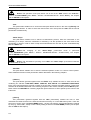
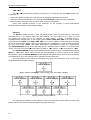
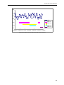
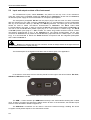
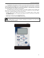
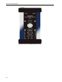
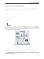
SVAN 958 USER MANUAL
2 MANUAL CONTROL OF THE INSTRUMENT
The control of the instrument is developed in the fully "conversational" way. The user can
"programme" the operation of the instrument selecting the proper option from the MENU. Thanks to it,
the number of the control push-buttons of the instrument is reduced to nine.
2.1 Control push-buttons on the front panel
On the front panel of the instrument, there are located the following control push-buttons:
1. <ENTER>, (<Menu>), [<Save>]
2. <ESC>, (<CAL>), [<Pause>]
3. <Shift>, [Markers]
4. <Alt>, [Markers]
5. <
>
6. <
>
7. <
>
8. <
>
9. <Start / Stop>
The name given in brackets (...) denotes the second push-button function which is available
after pressing it in conjunction (or in sequence) with the <Shift> push-button. The name given in square
brackets […] denotes the push-button function which is available after pressing it in conjunction
(or in a sequence) with the <Alt> push-button.
Control push-buttons of the SVAN 958 instrument
<Shift>
The second function of a push-button (written in red colour on a push-button) can be used when
the <Shift> push-button is pressed. This push-button can be used in two different ways:
•
as SHIFT in the keyboard; both push-button must be pressed in parallel
•
as 2nd Fun; this push-button can be pressed and released before pressing the second one
<Shift> pressed in conjunction with <Alt> enables the user to enter the MARKERS on the logger
plots during the measurement.
2-1
SVAN 958 USER MANUAL
.
Notice: The operation of this push button can be set as the “Shift” mode or the “2nd Fun.”
mode in the SHIFT MODE (path: MENU / SETUP / KEYBOARD SETUP / SHIFT MODE), see Chapter
with the SETUP list description.
<Alt>
This push-button enables one to choose the third push-button function in the case of [<Save>] and
[<Pause>] push-buttons. In order to select the third function user must press the <Alt> and the second
push-button simultaneously.
<Start / Stop>
This push-button enables one to start the measurement process, when the instrument is not
measuring or to stop it, when the instrument is measuring. It is also possible to set such mode of this
push-button, in which in order to start or stop the measurements the user has to press it simultaneously
with the <Shift> one.
Notice: The changing of the <Start / Stop> push-button mode is performed
in the START/STOP (path: MENU / SETUP / KEYBOARD SETUP / START/STOP), see Chapter
with the SETUP list description.
Notice: The simultaneous pressing of the <Alt> and <Start / Stop> push-buttons switches
the instrument on and off.
<ENTER>
This push-button enables one to enter the selected operation mode or to confirm control options.
Some additional functions of this push-button will be described in the following chapters.
(<Menu>)
This push-button (pressed together with the <Shift> one) enables the user to enter the main list
containing six sub-lists: FUNCTION, INPUT, DISPLAY, FILE, SETUP and AUXILIARY FUNCTIONS.
Each of the mentioned above sub-lists consists of the sub-lists, elements and data windows. These main
sub-lists will be detailed described in the following chapters of the manual. Double pressed <Menu> pushbutton enters the HISTORY list containing eight last opened sub-lists. It often speeds up the control of the
instrument.
[<Save>]
This push-button (pressed together with the <Alt> push-button) enables the user to save
measurement results as a file in the internal instrument’s memory or on the USB memory stick. There are
two ways of saving a file: with AUTO NAME option - saving a file with the name automatically increased
by one (e.g. JAN0, JAN1, JAN2) or save a file by editing its name in the FILE NAME position (see Chapter
with the FILE list description).
2-2
SVAN 958 USER MANUAL
<ESC>
This push-button closes the control lists, sub-lists or windows. It acts in opposite to the <ENTER>
push-button. When the window is closed pressing the <ESC> push-button, any changes made in it are
(in almost all cases) ignored.
[<Pause>]
This push-button enables one to break temporary the measurement process. The subsequent
pressing of the <Pause> push-button deletes the measurement result from the last one second.
Up to fifteen last seconds of the measurement can be cancelled in this way.
<
>, <
>
These push-buttons enable one, in particular, to:
• select the options in an active position in the "horizontal direction" (e.g. filter: LIN, A, C or G, Integration
period: 1s, 2s, 3s, … etc.)
• select the measurement result to be displayed (e.g. PEAK, MAX, MIN, etc.) in one-channel and multichannel modes of result’s presentation)
• control the cursor in SPECTRUM, LOGGER and STATISTICS modes of result’s presentation
• select the position of the character in the text edition (i.e. in the FILE NAME menu)
• switch on/off markers 2 and 3
• switch on/off the BACKLIGHT of the display ( <
>+ <
> pressed together)
(<
>, <
>)
The <
>, <
> push-buttons pressed in conjunction (or in sequence) with the <Shift> enable
the user, in particular, to:
• speed up the changing of the numerical values of the parameters (i.e. the step is increased from 1
to 10 in the setting of START DELAY - path: MENU / INPUT / MEASUREMENT SETUP /
START DELAY)
• insert or delete a character in the text edition modes
• change the statistics class (the number displayed after the letter L) in one-channel and multi-channel
modes of result’s presentation
Some other possible reactions of the instrument on the pressing of these push-buttons
will be described in details in the following chapters.
<
>, <
>
The <
>, <
> push-buttons enable one, in particular, to:
• change the mode of result’s presentation
• select the proper character from the list in the text edition mode
• switch the active sub-list in a list
• programme the Real Time Clock (RTC) and TIMER
• switch on/off markers 1 and 4
Some other possible reactions of the instrument on the pressing of these push-buttons will be
described in details in the following chapters.
2-3
SVAN 958 USER MANUAL
.
(<
>, <
>)
The <
>, <
> push-buttons pressed in conjunction (or in sequence) with the <Shift> enable one,
in particular, to:
• change the relation between the Y-axis and X-axis of all plots presented on the screen
• switch the channels and profiles in one-channel and STATISTICS modes of result’s presentation
• switch the active channel in multi-channels mode of result’s presentation
Some other possible reactions of the instrument on the pressing of these push-buttons
will be described in details in the following chapters.
[Markers]
The Markers enable the user to mark the special events, which occurred during the performed
measurements (i.e. the airplane flight, the dog’s barking, the train’s drive etc.). In order to enter
the markers the logger has to be switched on (path: MENU / INPUT / LOGGER SETUP /
LOGGER MODE: ON) and one or more logger options (PEAK, MAX, MIN, RMS in the case of sound
measurements and PEAK, P–P, MAX, RMS, VDV in the case of vibration measurements) in channels
have to be chosen (path: MENU / INPUT / LOGGER SETUP / CHANNEL x). In order to enter the marker
the user must press <Shift> and <Alt> push-buttons simultaneously during the measurement.
The ENTER MARKER window opens and there are four available marker numbers. To choose marker
number 1 the user must press <
> push button (number 2 - <
>, number - 3 <
> and number 4 - <
>).
The ENTER MARKER window closes automatically and chosen marker is activated (after pressing
<Shift> + <Alt> again active marker number will be highlighted). In order to switch off the marker,
the user has to open the ENTER MARKER window and press this push-button, which refers to the marker
to be switched off. Up to four markers can be switched on at the same time.
The current state of the markers is indicated in the logger’s file and can be used to show them
using dedicated presentation software.
Display with the “MARKERS” (after pressing <Alt> and <Shift> together)
Displays with the activated markers
The exemplary presentation of the markers on the time-history plot is shown below (to view a plot
with the markers the user has to transfer data to the proper software).
2-4
SVAN 958 USER MANUAL
80
70
60
50
LEQ
Marker 1
40
Marker 2
Marker 3
30
Marker 4
20
13:30:00 13:30:09 13:30:17 13:30:26 13:30:35 13:30:43 13:30:52
Time-history plot with the indication of the active markers
2-5
SVAN 958 USER MANUAL
.
2.2 Input and output sockets of the instrument
The measurement inputs, called Channels, are placed on the top cover of the instrument.
There are 4-pins Lemo compatible socket type ENB.0B.304 for Channels 1–3 and TNC for Channel 4,
all with IEPE power supply for the accelerometers or microphone preamplifiers.
The microphone preamplifier SV 12L has the proper plug-in with the screw for direct connection
with the instrument to the TNC connector (Channel 4) but it is recommended to use the preamplifier
with any of the extension cables (i.e. SC 26) or the SA 08 gooseneck. The same type of the connector
should be used to attach one-channel accelerometer to Channel 4. The SC 27 coiled cable
is recommended in this case. In order to connect the SV 12L microphone preamplifier to Channels 1–3
one has to use the SC 49 cable (LEMO 4-pins plug to 3 * TNC sockets, 0.7 meters long). The SC 49
or SC 39P (LEMO 4-pins plug to 3 * BNC sockets, 0.7 meters long) cables should be used to connect
one-channel accelerometer to any of the Channels 1–3. The triaxial accelerometers can be easy
connected to Channels 1–3 by means of the SC 38 cable (4-pins Microtech to LEMO 4-pins, 2.7 meters
long). It is recommended to attach the SV 25 dosimeter microphone with the integrated preamplifier
and a cable to Channel 4.
Notice: Pay attention that the TNC connector should be always twisted to the light resistance
but the LEMO connector is a push-pull only.
The full description of the signals connected to the sockets is given in the Appendix C.
Top cover of the SVAN 958 instrument in 1:1 scale
In the bottom cover there are four sockets, placed from the right to the left as follows: Ext. Pow.,
USB Host, USB Device and I/O.
Bottom cover of the SVAN 958 instrument in 1:1 scale
The USB 1.1 Client interface (the USB Device socket) is the serial interface working with 12 MHz
clock. Thanks to its speed, this interface is widely used in all PCs. In the instrument, the standard 4-pins
socket is used described in details in Appendix C.
The USB Host 1.1 interface can be used to connect the external storage, enabling the device
to register virtually infinite sequence of measurement results.
2-6
SVAN 958 USER MANUAL
The Ext. Pow. socket located on the bottom cover of the instrument is Marushin MJ-14 compatible
socket, dedicated for the standard Φ 5.5 / 2.1 mm plug (the right one in the Fig. above). The user can
connect the external mains adapter (110 V / 230 V) which furnishes the proper DC level. The instrument
can be charged from the external DC source (6 V / 500 mA DC ÷ 15 V / 250 mA DC). The current
consumption depends on the voltage of the power supplier.
The additional input / output socket, called I/O, is 1-pin LEMO compatible socket type ERN.00.250
(the left one in the Fig. above). The function of this socket can be selected from menu (path: MENU /
SETUP / EXT. I/O SETUP / MODE). The socket can be used as:
• analogue output with the signal from the input of the analogue / digital converter (before
the correction); this signal can be registered using magnetic recorder or observed on the oscilloscope
(the ANALOG setting)
• digital input for external interrupt (the DIGITAL IN setting)
• digital output for external trigger (the DIGITAL OUT setting)
Notice: Switch the power off before connecting the instrument to any other device
(e.g. a printer or a Personal Computer).
Front panel of the SVAN 958 instrument in 1:1 scale
2-7
SVAN 958 USER MANUAL
.
Rear panel of the SVAN 958 instrument in 1:1 scale
2-8