1
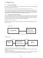
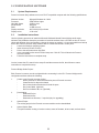
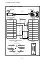
User Manual
Protocol converter
PC-S, Serial to Serial
UMPCSA
Rev 1.0, 06/2006
COPYRIGHT NOTICE
This manual is a publication of Brainchild Electronics Co.. Ltd. and is provided for use by its customers only. The contents of the manual are copyrighted by Brainchild Electronics; reproduction in whole or in part, for use other
than in support of Brainchild Electronics equipment, is prohibited without the specific written permission from Brainchild
Electronics.
SERVICE
If service is required then pack the unit in its original packaging container or, if unavailable, any suitable rigid container.
If a substitute container is used, surround the unit with shock absorbing material; damage in shipment is not covered
by the warranty. Include a letter with the unit describing the difficulty and Hardware Revision and Software Version.
Send to the following address:
Brainchild Electronic.Co.Ltd.
6F, 209, Chung yong Road, Nan Kang Dist, Taipei, Taiwan, R.O.C
Tel: +886-2-27861299
Fax: +886-2-27861395
Email: [email protected]
All returns will be tested to verify customer claims of noncompliance with the product warranty. Improper return
packaging, which makes verification impossible, will void the warranty. If noncompliance is verified and is not due
to customer abuse or the other exceptions described with product warranty, Brainchild Electronics will, at its option,
repair or replace the Product returned to it, freight prepaid, which fail to comply with the foregoing warranty, provided
Brainchild is notified of such noncompliance within the one-year warranty period.
ASSISTANCE
This manual is designed to provide the necessary information for trouble-free installation and operation of your new
Protocol conveters. However, if you need assistance, please call Brainchild Electronic Co. Ltd. at +886-2-27861299 Ext
613 or visit our web site at www. Brainchild.com.tw
MANUAL REVISION
If you contact us in reference to this manual, please include the following document number
Name
:
User Manual For PC-S
Document
:
UMPCSA, 06,2006
Revision
:
1.0
Revision Number
Document Number
Date
Description
Rev 1
UM\PCSA 06,2006
20-06-2006
Manual first edition
Warranty Certificate
For New product: This product is warranted against defects in materials and workmanship for a period of 12 months
from the date of shipment to Buyer.
For Rectified Products: Any product that will be replaced will have Warranty for 6 months or upto Original Product Warranty period whichever is greater.
The warranty is limited to repair or replacement of the defective unit at the option of the manufacturer. This warranty is
void if the product has been altered, misused, dismantled, or otherwise abused.
ALL OTHER WARRANTIES, EXPRESSED OR IMPLIED, ARE EXCLUDED, INCLUDING BUT NOT LIMITED TO THE
IMPLIED WARRANTIES OF MERCHANTABILITY AND FITNESS FOR A PARTICULAR PURPOSE.
MAINTENANCE & SERVICE : There are no parts that can be serviced by the user. Service should be performed on a
unit substitution basis only. Do not attempt to remove, replace or service any printed circuit board, components or any
hardware/software related with display product. If problem within the display product occurs, contact the factory for
service information or repair.
Preliminary
Protocol converter is a versatile gateway / Data sharer with Windows based configuration Software.
This manual will help you to safely install, configure and operate protocol converter.
All the safety warnings and precautions must be followed to ensure proper unit performance and personal safety.
Warnings used in this manual:
Danger Warnings are used to indicate situations, locations and conditions
that can cause serious injury or death.
DANGER
CAUTION
!
Caution Warnings are used to indicate situations and conditions that can
cause operator injury and/or unit damage
IMPORTANT
Protocol conveters are intended to be Gateways / Data sharer devices that can
also take control actions on request of device being connected. It is assumed
that the user is well acquainted with the PLCs / Inverters / Controllers being
used.
Any mechanical or electrical modification to the unit will void all warranties.
Contents
1. Introduction................................................................................................6
1.1 Purpose of this Manual
1.2 Introduction to Protocol converter
1.3 Protocol converter Applications:
1.4 Protocol converter Specifications
6
6
7
7
2.1
2.2
2.3
8
10
11
3.1 Introduction to Protocol converter
3.2 Protocol converter Operation-Configuration and Communication
2. Hardware........................................................................................................8
Dimensional Details and Mounting Instructions
Power Requirements
Communication Ports
3. Getting Started......................................................................................... 12
12
13
4. UNDERSTANDING pROTOCOL CONVERTER...........................................14
4.1
Protocol converter Modes
14
4.2
4.3
4.4
4.5
4.6
4.7
4.8
Multi-dropping of Devices using Protocol converter
Repeat Cycle
Control Word
Error Indication Bit
Communication Parameters
Status LEDs
Project Setup
18
19
19
20
20
20
21
5.1
5.2
System Requirements:
Installation Instructions:
22
22
6.1 Wiring Diagrams
6.2 RS422/RS485, 4 Wire connection diagram
6.3 RS 485, 2 Wire connection diagram
4.1.1 Master-Master configuration
4.1.2 Master-Slave configuration
14
16
5. Configuration Software.....................................................................22
6. CONNECTION Diagrams............................................................................ 23
7.COMMUNICATION CABLES for PC - S
7.1
7.2
7.3
7.4
7.5
7.6
7.7
7.8
7.9
7.10
7.11
7.12
7.13
7.14
7.15
AB SLC DH485 PORT TO PC - S (CA-007-00)
AB MICROLOGIX SERIES PLCs TO PC - S (CA-027A-00)
A B SLC DF1 PORT TO PC - S (CA-027B-00)
AROMAT FP0/FPM TO PC - S (CA-015A-00)
AROMAT FP1 TO PC - S (CA-015B-00)
AROMAT FP2 TO PC - S (CA-015D-00)
CALISTO PLC TO PC - S (CA-090-00)
GE 90 SERIES PLC TO PC - S (CA-002-00)
GE VERSAMAX PLC TO PC - S (CA-002B-00)
GE VERSAMAX PLC TO PC - S (CA-002A-00)
IDEC MICRO3 TO PC - S (CA-025A-00)
KEYENCE KV PLC TO PC - S (CA-018-00)
LG MASTER K SERIES PLC TO PC - S (CA-037-00)
MITSUBISHI FX SERIES PLC TO PC - S (CA-008B-00)
MITSUBISHI FX0 PLC TO PC - S (CA-008A-00)
23
23
23
24
24
25
26
27
28
29
30
31
32
33
34
35
36
37
38
7.16
7.17
7.18
7.19
7.20
7.21
7.22
7.23
7.24
7.25
7.26
7.27
7.28
7.29
7.30
7.31
7.32
7.33
7.34
7.35
MODICON MICRO-CONTROLLER TO PC - S (CA-009B-00)
MOISTURE ANALYSER TO PC - S (CA-098-00)
OMRON CQM1 PLC TO PC - S (CA-006B-00)
OMRON CQM/CPM CMOS PORT TO PC - S (CA-006A-00)
RHEONIC MASS FLOW METER TO PC - S (CA-091A-00)
RHEONIC MASS FLOW METER TO PC - S (CA-091B-00)
SIEMENS S7-300 SERIES PLC TO PC - S (CA-077-00)
SIEMENS STEP 7 MICRO (S7-200) PLC TO PC - S (CA-029-00)
TELEMECHANIQUE TSX-07/TSX-37 PLC TO PC - S (CA-026A-00)
TOSHIBA T1 LINK PORT TO PC - S (CA-046A-00)
TOSHIBA T1 PLC TO PC - S (CA-019A-00) TOSHIBA T2 LINK PORT TO PC - S (CA-046B-00)
TOSHIBA T2 PLC TO PC - S (CA-019B-00)
TOSHIBA VF-S7 TO PC - S (CA-050-00)
METTLER TOLEDO TO PC - S (CA-103-00)
SARTORIUS TO PC - S (CA-104-00)
BAUMULLER DRIVE (RS485 4-WIRE) TO PC - S (CA-042A-00)
BAUMULLER DRIVE (RS485 2-WIRE) TO PC - S (CA-042B-00)
THOMSON TECHNOLOGY CONTROLLER TO PC - S (CA-117-00)
RS232 CABLE FOR PC - S 39
40
41
42
43
44
45
46
47
48
49
50
51
52
53
54
55
56
57
58
8. Troubleshooting Guide........................................................................59
9. Supported PLC’s List for Protocol converter, PC - S....................61
1. INTRODUCTION
1.1
Purpose of this Manual
The intention of this Operation Manual is to provide a guide for Safe installation, Configuration and operation of serial to serial Protocol converter.
Read this operation manual thoroughly before installing and operating Protocol converter.
This document is based on information available at the time of its publication. While efforts have been
made to be accurate, the information in this document may not cover all the details or variations in hardware or software. Features described herein may not be present in all hardwares. Brainchild Electronics
reserves the right to update information in this publication without prior notice.
1.2
Introduction to Protocol converter
Protocol converters provide interface between different devices having different communication protocols.
It also provides interface between same communication protocols (Example: Data sharer between two
slaves having the same protocol). Protocol conveters communicates with PLCs / Inverters / Controllers
using RS232 / RS422 / RS485 (2 / 4 wire) or CMOS serial communication.
Configuration of Protocol converter:
Each Protocol converter has to be configured using Windows based configuration Software before connecting it to the PLC.
Configuration
Protocol
Converter
Computer
RS232 Interface cable
Normal Operation:
X-Protocol
PLC
Modbus RTU
Protocol
Converter
RTU
COM2
COM1
Connect PLC with specific protocol to COM1 of Protocol converter.
Connect PLC or Inverter or Transmitter etc. which supports Modbus RTU protocol on COM2 of Protocol
conveter.
Correct cables are required.
Once, Protocol converter configured and download project from PC from Protocol bridge studio software,
then Protocol converter exchange data between the two devices as per configuration,
1. INTRODUCTION
1.3
Protocol converter Applications:
Protocol converter connects one field device to another over a serial link irrespective of their protocols.
User can define the blocks of registers to be fetched from one device and to be transferred to the other.
Protocol converter units have been used in various different applications across many industries. The typical configurations include the followings:
PLC as Master on the Modbus network
X-Protocol
PLC
Modbus RTU
Protocol
Converter
COM1
1.4
Inverter
COM2
PID controller
Protocol converter Specifications
Power Supply
: 24 VDC +/- 10 %, 100 mA max
Communication
: Two ports as follows:
PLC1 : RS232C / RS422 / RS485 / CMOS
For configuration and PLC communication
PLC2: RS232C / RS422 / RS485 / CMOS
For PLC communication
Indications
: PLC1 LED - for PLC1 port status
OK LED - for Protocol converter status
PLC2 LED - for PLC2 port status
Temperature
: Operating: 0 to 60 °C
Storage: - 40 to 90 °C
Humidity
: 10% to 90% (Non condensing)
Immunity to ESD
: Level 3 as per IEC1000-4-2
Immunity to Transients : Level 3 as per IEC1000-4-4
Radiated Susceptibility : Level 3 as per IEC1000-4-3
Emissions
: EN55011 CISPR A
Certifications
: CE, cUL.
Dimensions
: 105mm (L) X 40mm (D) X 51mm (W) (DIN RAIL mounting)
Weight
: 125 g approximately
2. HARDWARE
2.1
Dimensional Details and Mounting Instructions
Protocol converter unit can be mounted on a back panel or on a DIN rail or can be left hanging. Each
Protocol converter unit comes with a separate DIN rail plate when it is packed. User will have to attach
the DIN rail plate to the unit if it has to be mounted on a panel or DIN rail. If it has to be left hanging, make
sure to screw the cables to the DB9 connectors on the Protocol converter unit. DIN rail plate also has the
provision to screw the unit to the back panel. Following drawing shows how to attach the DIN rail plate to
PLC 1
(RS232/RS485/
PLC1
OK
PLC2
C
US
LR 109782-2
R
PENDING
Slot for
clamp
DIN rail
clamp
PC-S
}
DC+
DC-
24VDC
+/- 10%
EARTH
(RS232/RS485/
CMOS)
PC-S
DIN rail
clip
DIN rail
plate
Following drawing shows the dimensional details of Protocol converter with DIN rail plate
50.5mm
40mm
PLC 1
Screw
Hole
(RS232/RS485/
PLC1
OK
PLC2
C
US
LR 109782-2
R
PENDING
PC-S
104.4 mm
}
DC+
DC-
24VDC
+/- 10%
EARTH
Screw
Hole
(RS232/RS485/
CMOS)
2. HARDWARE
Following drawing displays how the unit can be mounted on the DIN rail:
PLC 1
PLC 1
(RS232/RS485/
(RS232/RS485/
PLC1
OK
PLC2
C
US
LR 109782-2
R
PENDING
R
PENDING
PC-S
}
DC+
DC-
PLC1
OK
PLC2
C
US
LR 109782-2
PC-S
}
DC+
24VDC
+/- 10%
DC-
EARTH
24VDC
+/- 10%
EARTH
(RS232/RS485/
(RS232/RS485/
CMOS)
CMOS)
Follow instructions given below:
1.
Attach the DIN rail plate to the unit using the clamps on the DIN rail plate.
2.
Pull out the clip of the plate.
3.
Put the unit on the DIN rail.
4.
Push the clip in to secure the unit on the DIN rail.
Following drawing displays how the unit can be mounted on a back panel:
PLC 1
(RS232/RS485/
PLC1
OK
PLC2
C
US
LR 109782-2
R
PENDING
PC-S
}
DC+
DC-
24VDC
+/- 10%
EARTH
(RS232/RS485/
panel
Follow instructions given below:
1.
Attach the DIN rail plate to the unit using the clamps on the DIN rail plate.
2.
Insert screws in the 4 holes provided on the DIN rail plate.
3.
Tighten the screws to secure the unit in the panel.
2. HARDWARE
2.2
Power Requirements
Protocol converter is a 24VDC powered unit. Power should be applied on the PCB Terminal block on the
Protocol converter unit. Power rating is +24VDC +/- 10%, 100mA max. Please follow the instructions given
below when making power supply connections:
Follow the sticker wiring diagram on the unit which shows terminals for the
positive DC, negative DC and ground.
To make a connection strip about 1/4” (6mm) of insulation of the wire and turn the
connector screw counter-clock wise until the gap is wide open. Insert the wire all
the way in and turn the screw clockwise until it is tight.
Wire lengths should be minimum. Wires should run in pairs with a neutral or
common paired with a live or signal wire.
A fuse should be connected from outside wherever required for protocol converters
!
Protocol converter products are housed in a molded ABS plastic case which
eliminates any electrical shock hazard. Hence Safety ground is not required to be connected to the chassis of the unit.
!
The DC ground is not directly coupled to Earth ground internally. The unit is
designed to operate properly whether or not the DC ground is connected to the
Earth ground. We do recommend, however, that if the DC ground has to be
connected to the Earth ground, the Earth connection should be made to a central
star point as poor site earths can introduce noise into a system.
Do not power Protocol converter and inductive loads with the same power supply even though there is enough immunity in the Protocol converter to withstand the transients present on these lines. Avoid using power supplies with large capacitive outputs, which may cause problems if power is cycled within a short time period. If wiring is to be exposed to lightening or surges, use appropriate surge suppression devices.
Keep AC, high energy and rapidly switching DC wiring separate from signal wires.
Connecting high voltages or AC power mains to the DC input will make Protocol converter unusable and may create an electrical shock hazard to personnel. Such a failure or shock could result in serious personal injury, loss of life and/or equip
ment damage.
DC voltage sources should provide proper isolation from main AC power and similar
!
10
2. HARDWARE
2.3
Communication Ports
Protocol converter unit has two communication ports. Both the ports have DB9 type connectors and are
compatible with RS232C, RS422, RS485 and CMOS signal levels. PLC1 (also known as COM1) and
PLC2 (also known as COM2) have exactly the same pin outs which are as shown below:
RX- (RS422/RS485)
TX- (RS422/RS485)
TXD (CMOS)
+5VDC*
*(DO NOT USE)
PLC1 / PLC2 ports
9
8
7
6
9
6
5
5
4
3
2
1
1
GND
RX+ (RS422/RS485)
RXD (RS232C/CMOS)
TXD (RS232C)
TX+ (RS422/RS485)
DB9 Female
Pin Description
Pin 1.
2.
3.
4.
5.
6.
7.
8.
9.
Name
TX+
TXD
RXD
RX+
GND
+5VDC
TXD
TX-
RX-
Signal Level
RS422 / RS485
RS232
RS232 / CMOS
RS422 / RS485
-
-
CMOS
RS422 / RS485
RS422 / RS485
Description
Differential Transmit +, also referred as TXA
Transmit
Receive
Differential Receive +, also referred as RXA
Signal Ground common to all signals.
DO NOT USE
Transmit
Differential Transmit -, also referred as TXB
Differential Receive -, also referred as RXB
User can convert RS485 4 wire + Signal Ground system to a 2 Wire + Signal Ground system by shorting
following signals in the communication cable:
TX+
TX-
RX+
RXSG
A
B
SG
Note: If user has attached shield to Earth on Device end, leave the shield open on Protocol converter end. If user has connected shield to Signal Ground on Device end, connect shield to Signal
Ground on Protocol converter end.
Upto 31 Devices can be multi-dropped on RS485 port of Protocol converter.
11
3. GETTING STARTED
3.1 Introduction to Protocol converter
Protocol converter is a Gateway / Data sharer for devices like PLCs, inverters (Adjustable Speed Drives),
and other Controllers. Protocol converter has two serial ports that connect with two different devices.
These devices share data through Protocol converter. Protocol converter communicates with a device to
get the information required by the device connected on the other port. The device that requires data is
called Destination Device and the device that provides data is called Source Device. Information could be,
- value of a PLC register.
- status of a PLC coil.
- Command from Source Device to Destination Device to perform any action at the destination
end.
3.2
Protocol converter Operation - Configuration and Communication
Protocol converter can communicate with any two devices using appropriate cables and configuration.
Microsoft Windows® based configuration software, Protocol Bridge Studio Setup, configures the Protocol
converter unit. ‘Configuration’ means making the Protocol converter unit work as per system requirements.
Complete configuration for a Protocol converter using the Protocol bridge studio Setup is termed as a
‘Project’. A Project consists of Devices to be attached on two ports, Communication settings for two ports
to communicate with two devices, Register addresses for data transfer, Conditions for data transfer etc.
Protocol converter can now communicate with the specified devices without any change in the Protocol
converter hardware. To communicate with a device, Protocol converter needs Communication Drivers for
the devices and Protocol converter - Device communication cables.
Each Device has a unique and predefined protocol for communication. Protocol converter driver has this
protocol to communicate with the desired device. As two devices are connected on Protocol converter, it
requires two drivers for communication.
User MUST download Project, PLC1 driver and PLC2 driver in Protocol converter before installing
any system using Protocol converter. Protocol converter can accept drivers and configuration data on
either of the ports. User needs a special RS232 Interface cable for downloading configuration from PC to
Protocol converter.
If any change in the current / working project is made, user must download the changed project
from PC to Protocol converter.
Pin details of RS232 Interface cable for are as follows:
DB9 Male (Protocol converter)
2
DB9 Female (PC)
2
IMPORTANT NOTE:
AS Protocol converter HAS MULTIPLE SIGNALS ON ITS COMMUNICATION PORTS, PC CABLE for
Protocol converter MUST HAVE ONLY THREE RS232 SIGNALS (TXD, RXD AND GND) AS MENTIONED ABOVE.
12
3. GETTING STARTED
Protocol converter needs Firmware, Project and TWO drivers to communicate with two devices. Firmware
is factory programmed. If both or one of the drivers has not been downloaded in Protocol converter, Protocol converter permanently waits for PC download (indicated by continuous blinking of the OK LED).
Create project as per system requirements. Select PLC1 Driver, PLC2 Driver and Project for downloading.
PC-S can be configured by following method.
1.If both the drivers are downloaded, at power up Protocol converter polls for PLC1 / COM1 device (OK LED steady on max upto 5 seconds). If no device is found on this port, Protocol converter waits for PC download on either of the ports (OK LED blinking for 10 seconds). If PC download is not established,
Protocol converter will again poll for PLC1 / COM1 device. This sequence continues till either of the
communication is established.
2.If communication with PLC1 / COM1 device is established, Protocol converter tries to connect with
PLC2 / COM2 device. If this communication is not successful, Protocol converter polls for PC download. Once the project is configured in Protocol Bridge Studio software, connect RS232 interface cable from PC
to Protocol converter and Download PLC1 / COM1 driver, PLC2 / COM2 driver and Project.
Software will ask user if the Protocol converter has to be reset. Protocol converter must be reset unless
user wants to download setup again.
IMPORTANT:
1. When user wants to establish PC communication on one port, communication on the other
port should not interrupt PC communication. It is advised that communication on the other
port be stopped to ensure error free PC communication.
PC download scheme for PC-S models with Bootblock version 2.00A :
PC-S configured by either of the following two methods:
METHOD I
1. Connect configuration Cable and power cables to PC-S
2. Apply power to PC-S
3. Download PLC1 driver, PLC2 driver and project within 10 seconds after power-on.
METHOD II
1. Short pins 3 and 4 on PLC1 port of PC-S for at least 1 second after power-on. Remove the short.
Now PC-S permanently waits for PC download. Connect PC download cable.
2.
Download PLC1 driver, PLC2 driver and project.
The unit will automatically return to normal operation mode after a download cycle. If the user wants to
perform another download user has to bring the unit back into configuration mode using Method I or
Method II.
13
4. UNDERSTANDING PROTOCOL CONVERTER
4.1
Protocol converter Modes
Protocol converter has two modes of operation: Master-Master and Master-Slave. Before explaining these
modes further Master and Slave concept should be explained.
Master:
Master is a Device which initiates communication.
Slave:
Slave is Device which processes Master’s query, takes necessary action and responds to the query, if
necessary.
4.1.1
Master-Master configuration
In this mode both Protocol converter ports (PLC1 & PLC2) are master in nature and devices connected
on these ports are slave. Protocol converter ports initiate communication when the proper Protocol converter-Device communication cable is attached. Data is transferred in blocks. This transfer can either be a
continuous process or as per requirement. A control word (Section 4.4), present in device on either side,
enabled from Protocol bridge studio Setup Software, can control the block execution.
When control word is disabled, then block transfer is a continuous process. A block of data is fetched from
one device and transferred to the other device. The amount of data to be transferred (Number of words)
depends on Block definition in “Block Definition Area” in Configuration Software. One block is executed at
a time. A cycle consists of execution of blocks from #1 to #n.
Execution of blocks is performed as follows,
Block #1
Block #2
Block #3
Block #4
.
.
.
.
.
Block #n
When Control word is enabled, it decides which block has to be executed by writing a specific data
in the control word. Please refer to Example 4.1 for description on defining Blocks in Master - Master
configuration.
14
4. UNDERSTANDING PROTOCOL CONVERTER
Example 4.1
Master to Master configuration
This configuration can be used to make Rockwell PLC function as a Master at PLC1. Configure AB DF1 protocol for COM1, select Rockwell Micrologix 1000 Series PLC, Configure COM2 as
Modbus (Master) - RTU. Once protocols and devices selected for COM1 and COM2, then click on
“Configure” at the Menu available at Bottom side of the protocol bridge studio configuration software screen. Then new spread sheet will be opened. Now user has to enter all the following details
1.
2.
3.
4.
5.
6.
7.
# Words defines number of registers/coils to be read / written between two devices. Source PLC: Source device for data availability
Source ID: Address of the source device
Source address: Register/coil address in the source device for data transfer
Destination PLC: destination device for data transfer
Destination ID: Address of the destination device
Destination address: Register/coil address in the destination device for data transfer
Block #1: Protocol converter reads 7 words starting from N7:0 from Rockwell PLC and write these seven
words data to Modbus Master device in holding registers starting from 400001.
Block #2: Protocol converter reads Modbus Master holding register 400010 and writes it to Rockwell Master integer register N7:020
As this example has only two blocks, Protocol converter will execute Block #1 after executing Block #2
continuing this cycle forever.
Notes:
1)
Maximum 255 blocks can be configured in any mode.
2)
In Master-Master configuration, typical time required to execute one block is 75 msec.
approx.
Please refer to Example 4.2 for description on defining register / coil maps in Master - Slave configuration.
15
4. UNDERSTANDING PROTOCOL CONVERTER
4.1.2
Master-Slave configuration
In this mode, one of the Protocol converter ports is a master and other is the slave so the devices connected on these ports are slave and master respectively. Blocks do not control data transfer in this mode.
Data transfer takes place only when Master Device, connected on slave port of Protocol converter, sends
a request to read / write data. This mode requires mapping registers / coils for data transfer. Mapping
means defining one or multiple registers / coils in the Slave Device corresponding to one or multiple registers / coils in the Master Device. Mapping can be done using the Block definition area, so in this mode,
any Block is used for mapping registers / coils of the two devices.
In Block Definition area, # Words Field indicates number of registers / coils to be mapped linearly from the
starting addresses of the Source Device to the Destination Device. Maximum number of registers / coils
that can be mapped is 255, but this does not mean that Master Device has to read / write 255 registers /
coils in one command. For example, if user wants to map register DM0 to DM9, he has to define a single
block of 10 registers starting from DM0.
In one command Master can read / write registers / coils from one Block only, so if multiple registers
are to be read / written using a single command, # Words also limits the maximum number of registers /
coils to be read / written. Number of registers to be read /written in one command also depends on
- protocol of BOTH the devices
- Buffer capacity of Protocol converter.
Please refer to Example 4.2 for description on defining register / coil maps in Master - Slave configuration.
16
4. UNDERSTANDING PROTOCOL CONVERTER
Example 4.2
Modbus/Slave configuration
This configuration can be used to make Rockwell PLC as a Master. Configure Protocol converter COM1
ports as: DF1 Protocol - Allen Bradley SLC-500 Series, COM2 Protocol - Modbus Slave. Once entered
into configuration, source PLC will be shown as Modbus Slave and Destimation PLC as AB DF1 Rockwell
PLC. No need for the user to select source and destination PLC. Please neglect the naming conventions
of source and destination when you are using Master/Slave configuration.
Block #1 maps 5 coils of Rockwell PLC starting from B3:000/000 to Modbus Slave coils starting from
I00001. Block #2 maps 7 registers of Rockwell PLC starting from N7 000 to Modbus Slave registers
starting from 300001.
Here # Words field contains 5 coils in block 1 and 7 registers in block 2, so if protocol and Protocol
converter buffer permit, Modbus Master can access 5 coils / 7 registers in one command. For ex: In
case of Toshiba PLC, the limitation is 28 registers/coils. This is the limitation in Toshiba protocol. So
max. of 28 registers/coils can be exchanged. Simillarly for different PLC protocols, this numbers will
vary. During configuration, once u select the source PLC, then if you are trying to enter more number
of registers then particular PLC protocol supports, then you will get error message saying that protocol or protocol buffer is not not sufficiant. In this case, decrease the number at # words and try once
again.
In above example, request from Modbus Master is executed as follows:
1.
Rockwell PLC acting as Master sends command to Protocol converter for setting Bit register B3:000/000 to ‘1’.
2.
Protocol converter searches defined Blocks and checks whether this coil is mapped to any coil in the Modbus Slave.
In example 4.2, Bit register B3:000/000 is mapped to Modbus slave coil I00001 in Block 1. Protocol converter accepts this command and sets Modbus slave coil I00001 ON.
If Master sends a command to read / write a register / coil not defined in any Block then Protocol
converter sends exception response to master.
NOTES:
1)
If multiple registers / coils are to be read or written in one command, then all the regis
ters / coils have to be defined in one Block.
2)
As Protocol converter Setup Software is common for both the Protocol converter Mod
bus master/ Master and Master/Slave modes, titles in the Block Definition Area, source PLC and Destinatino PLC may not be appropriate when using Protocol converter in Master - Slave mode. Hence please neglect naming convention in Master/Slave Mode.
3)
Maximum 255 blocks can be configured in any mode.
4)
In Master - slave mode, If somebody mapped read only registers or coils at destination end to any registers at source end, it’s users responsibility that these registers are not going to be written by master.
17
4. UNDERSTANDING PROTOCOL CONVERTER
4.2
Multi-dropping of Devices using Protocol converter
Protocol converter supports multidropping on both the ports. Following illustration explains multidropping of devices on Protocol converter ports. Devices with protocols that support networking can be multidropped on RS485 port of Protocol converter. Maximum 31 devices can be networked using RS485 ports.
Node 1
Node n
PLC
Protocol
Converter
Node 1
Motor
Drive
.
.
PLC
Node n
PID Controller
Example 4.3:
Suppose Protocol converter is used to share data between multiple Modicon PLCs (Modbus Slave) to
multiple devices (Modbus Slave). Master - Master mode has to be used to enable data sharing. User must
define Blocks for sharing data.
Source PLC and Destination PLC appears as ‘Com1’ and ‘Com2’ before the name Modbus when protocols are same on both the ports.
Source ID / Destination ID: These fields define the device ID on respective port side of Protocol converter.
So using ID’s it is possible to transfer data from device#1 on port1 to device#2 of port2.
18
4. UNDERSTANDING PROTOCOL CONVERTER
4.3
Repeat Cycle
User can control Block execution by using the Repeat Cycle field. This number decides whether the
Block will be executed in each cycle. Larger the number lower the priority of the Block. Range for Repeat
Cycle setting is 1-99.
Repeat Cycle = 1 ………… Highest priority
Repeat Cycle =99 …………Lowest priority
Repeat cycle is important when using Protocol converter in Master - Master mode. If Protocol converter
is used in Master - Slave mode, Repeat Cycle field should be kept as ‘1’.
Repeat cycle defines the number of times a Block will be skipped while executing Blocks in a sequential
manner. Block will not be executed for [Repeat Cycle - 1] cycles. So if Repeat Cycle for a Block is 1, it will
be executed in each cycle whereas if Repeat Cycle is 2, then this Block will NOT be executed in alternate
cycles.
For example, suppose Blocks are defined with following Repeat Cycles:
Block #1
Repeat Cycle = 1
Block #2
Repeat Cycle = 2
Block #3
Repeat Cycle = 3
Block #4
Repeat Cycle = 4
After power up, Cycles will be executed as follows:
Cycle 1:
Block #1
Block #2
Block #3
Block #4
Cycle 2:
Block #1
Cycle 3:
Block #1
Block #2
Cycle 4:
Block #1
Block #3
Cycle 5:
Block #1
Block #2
Block #4
4.4
Control Word
Another way of controlling Block execution is by use of the Control Word. This feature is extremely useful
for small applications where less than 17 blocks are required. Control Word can be enabled or disabled in
Protocol converter Configuration. Normally Control Word is disabled for a New project. It can be enabled
just by clicking on check box in the setup software. Control Word can be chosen from any of the Devices
connected.
Control Word can only be used in Master-Master mode since no continuous data transfer takes place in
Master -Slave mode (data transfer only takes place on Master’s request)
When the Control Word is disabled, Block execution is totally controlled by Repeat Cycle settings. When
the Control Word is enabled, Block execution is controlled using discrete bits of that word.
Bit 0 in control word controls execution of Block #1
Bit 1 in control word controls execution of Block #2
:
Bit 15 in control word controls execution of Block #16
When a bit is high, ‘1’, corresponding Block is executed depending on its Repeat Cycle. When a bit is low,
‘0’, execution of corresponding Block is disabled.
19
4. UNDERSTANDING PROTOCOL CONVERTER
4.5
Error Indication Bit
This feature enables detection of communication breaks during error free communication between
Protocol converter and two devices. Communication breaks can occur due to no cable connection, wire
faults, device power failure at both ends of Protocol converter. An Error bit can be designated in each
external device connected to Protocol converter. Using this bit, fault at the PLC1 end can be reported to
PLC2 Device and fault at PLC2 end can be reported to PLC1 Device. When communication error occurs
on PLC1, Protocol converter sets error bit in PLC2 device. Error Indication Bit can only be used in MasterMaster mode. In Master-Slave mode any error can easily be detected by a communication time out on the
Master.
Error indication bit can be enabled using Protocol converter configuration software. Normally Error bit is
disabled for a New project. It can be enabled just by clicking on the check box in the setup software. Error
indication bit can be enabled in both or any one of the Devices connected to Protocol converter. Error Indication bit is “OFF” to indicate error free communication. In case of communication error on PLC2, Protocol
converter sets error bit on PLC1 port and vice versa.
4.6
Communication Parameters
Communication Parameters of Protocol converter can be set from configuration Software. This enables
Protocol converter to readily communicate with any device. Communication parameters for PLC1 and
PLC2 ports can be configured independently. This feature allows changes in Baud rate, Number. of stop
bits, Parity etc. at any time without downloading the driver for that particular device. After the driver for a
particular device is downloaded, the communication parameters can be changed simply by selecting new
communication parameters and downloading the same project.
4.7
Status LEDs
Protocol converter has 3 status LEDs located near PLC1 side. These LEDs indicate communication status
and Protocol converter operation. Three LEDs are identified as PLC1, OK and PLC2. PLC1 and PLC2
LEDs indicate communication status on two ports whereas OK LED indicates the Protocol converter
mode, either configuration or operation.
PLC1 LED
Status Description
Blinking
Communication on PLC1 is OK.
Off
No Communication on PLC1 due to
- Device fault.
- No power to Device.
- Cable fault.
- Wrong Communication Parameters.
OK LED
Status Description
Off
No power to Protocol converter.
Fast Blinking Protocol converter is waiting for download from PC.
Slow Blinking Communication error on PLC1 port. Error may be due to
- Device Fault.
- No power to either of the device.
- Cable fault.
- Wrong Communication Parameters.
Steady on
Communication OK on PLC1 port.
20
4. UNDERSTANDING PROTOCOL CONVERTER
PLC2 LED
Status Description
Off
No communication on PLC2.
Fast Blinking Communication with device on PLC2 is OK.
Slow blinking Protocol converter is trying to Communicate with the Device on PLC2, Device not responding due to - Device has no power.
- Cable fault.
- Wrong Communication Parameters.
4.8
Project Setup
This Chapter explains, how a simple Protocol converter project can be created and tested. To develop a
Protocol converter system, select appropriate Protocol converter model depending on the system requirements. A new project can be created as follows:
1. Define the Protocol converter System:
1.1
Protocol of Device(s) connected to PLC1
1.2
Protocol of Device(s) connected to PLC2
2. Load Microsoft Windows® based Protocol bridge studio Setup software.
3. Select devices to be connected on two ports.
4. Define Blocks for data transfer.
5. Set the communication parameters for the selected devices.
6. Set conditions for block execution if required (Repeat Cycle, Control Word etc.)
7. Apply power to Protocol converter.
8. Download the Project and Communication Drivers into Protocol converter.
9. Remove Configuration Cable from PLC1 Connect Protocol converter - Device cable to PLC1
10. Test system.
21
5. CONFIGURATION SOFTWARE
5.1
System Requirements:
Protocol converter Setup software runs on a PC/AT compatible computer with the following specifications:
Windows Version
Processor
Hard disk Space
Serial Mouse RAM
Display resolution Display colors 5.2
: Microsoft Windows 9x / 2000
: PENTIUM or higher
: 5 MB or more
: Required
: 16 MB or more
: 800 X 600 (VGA) or better
: 16 bit color
Installation Instructions:
Use the following procedure to install the Microsoft Windows® based Protocol bridge studio setup
software This installation shows the procedure to install the software from a CD Disk on drive E. On machines with different drive configurations, change the names as needed. It is recommended that a backup
disk of the Protocol converter setup software disk be created and stored in a safe place.
1. Launch the Windows operating system.
2. Insert the setup CD into CD-drive.
3. Point to the start button then click RUN
4. In the command line box enter E:\Disk1\setup.exe. Click OK. This will launch the Protocol
converter installer.
5. Follow the instructions to complete setup.
Or else, browse the CD, search for the setup file and then execute the file, then follow on screen
instructions to complete the setup.
Protocol Bridge Studio Project:
Each Protocol converter must be configured before connecting it to the PLC. Protocol bridge studio
configuration software allows the following:
1.
Create a new Protocol converter project
-
Select protocols for both communication ports of Protocol converter.
-
Create blocks for data to be shared.
-
Set Communication Parameters for both the ports.
-
Set Control Word. (Optional)
-
Set Error Indication Bit, etc. (Optional)
2.
Downloading.
-
Download Project
-
Download drivers
-
Download new firmware, if required (only for upgrading).
3.
Upload Project.
The existing project in the Protocol converter module can be viewed/edited.
4.
Upload System Data.
This option enables viewing of version number, status of firmware, drivers used, and boot block.
22
6. CONNECTION DIAGRAMS
6.1
Wiring Diagrams
User must ensure correct wiring for problem-free operation of Protocol converter. Each device being connected to Protocol converter has a unique communication port. Pin outs of communication ports of Protocol converter are given in section 2.3. Port details of the other devices can be found in the device manual.
Protocol converter has RS232, RS422, RS485 and CMOS compatible communication ports, so user can
directly connect any device with these communication signals.
This section gives wiring diagrams for connecting Protocol converter using various signal levels.
1.
Network of RS422 / RS485 4 wire + signal ground system
RT
RX+
RXTX+
TX-
RX+
RXTX+
TXRT
PC-S
RX+
RXTX+
TX-
RX+
RXTX+
TX-
DEVICE
DEVICE
DEVICE 2
RX+
RXTX+
TX-
Power: +24VDC
+ 10%
Note: User should add Termination resistor (RT=180 Ohm ) in Receive lines of first and last node.
Network of RS485 2 wire + signal ground system
DEVICE
A (+ve)
B (-ve)
GND
DEVICE
A (+ve)
B (-ve)
GND
RX+
RXTX+
TX-
PC-S
2.
Power: +24VDC
+ 10%
23
A (+ve)
B (-ve)
GND
A (+ve)
B (-ve)
GND
DEVICE 2
7. COMMUNICATION CABLES
AB SLC DH485 PORT TO PC-S (CA-007-00)
PC - S SIDE
AB SLC SIDE
7.1
2 mtr.
UNIT
8 PIN MODULAR CONNECTOR
(RS485)
DB9 MALE
(RS485)
Shield Wire
SIGNALS
Pin #
Pin #
SIGNALS
A
1
1
TX+
B
2
A
2
3
3
4
4
RX+
5
5
SG
SHIELD
6
6
SG
7
7
8
B
8 PIN MODULAR CONNECTOR PINOUTS
FRONT VIEW
Shield Wire
R.H.S. VIEW
Pin 1
(Left side)
8
TX-
9
RXDB9 MALE
PINOUTS
Pin 8
(Right side)
6
9
Cable insert
end
Cable insert
end
24
1
5
7. COMMUNICATION CABLES
7.2
AB MICROLOGIX SERIES PLCs TO PC - S (CA-027A-00)
PC - S SIDE
AB MICROLOGIX
SIDE
2 mtr.
UNIT
MINIDIN 8 PIN MALE
(RS232)
SIGNALS
SG
RXD
TXD
DB9 MALE
(RS232)
Shield Wire
Pin #
Pin #
SIGNALS
1
1
2
2
TXD
3
3
RXD
4
4
5
5
6
6
7
7
8
8
SG
9
8 PIN MINIDIN CONNECTOR PIN-Shield Wire
OUTS
6
DB9 MALE
PINOUTS
8
7
5
3
4
6
9
1
2
25
1
5
7. COMMUNICATION CABLES
7.3
A B SLC DF1 PORT TO PC - S (CA-027B-00)
AB SLC SIDE
PC - S SIDE
ATTACH
PLC
DB9 FEMALE
(RS232)
SIGNALS
UNIT
2 mtr.
DB9 MALE
(RS232)
Shield Wire
Pin #
Pin #
1
1
RXD
2
2
TXD
TXD
3
3
RXD
4
4
5
5
6
6
7
7
8
8
9
9
SG
DB9 FEMALE Shield Wire to DB9 body
PINOUTS
9
6
5
SIGNALS
SG
DB9 MALE
PINOUTS
6
9
1
26
1
5
7. COMMUNICATION CABLES
7.4
AROMAT FP0/FPM TO PC - S (CA-015A-00)
AROMAT FP0
SIDE
PC - S SIDE
2 mtr.
UNIT
MINIDIN 5 PIN MALE
(RS232)
DB9 MALE
(RS485)
Shield Wire
SIGNALS
Pin #
Pin #
SIGNALS
SG
1
1
TXD
2
2
TXD
RXD
3
3
RXD
4
4
5
5
SG
6
7
8
Shield Wire
DB9 MALE
PINOUTS
5 PIN MINIDIN CONNECTOR PINOUTS
4
9
5
2
3
6
9
1
27
1
5
7. COMMUNICATION CABLES
7.5
AROMAT FP1 TO PC - S (CA-015B-00)
ARPMAT FP1
SIDE
PC - S SIDE
2 mtr.
UNIT
DIN CONNECTOR MALE
(RS485)
DB9 MALE
(RS485)
Shield Wire
SIGNALS
Pin #
Pin #
SIGNALS
SG
1
1
TX+
TX-
2
2
RX-
3
3
4
4
RX+
TX+
5
5
SG
RX+
6
6
7
7
8
8
TX-
9
RX-
Shield Wire
DIN CONNECTOR
PINOUTS
DB9 MALE
PINOUTS
4
2
1
3
5
6
7
9
6
8
28
1
5
7. COMMUNICATION CABLES
7.6
AROMAT FP2 TO PC - S (CA-015D-00)
AROMAT FP2 SIDE
PC - S SIDE
UNIT
ATTACH
PLC
2 mtr.
DB9 MALE
(RS232)
SIGNALS
DB9 MALE
(RS232)
Shield Wire
Pin #
Pin #
1
1
TXD
2
2
TXD
RXD
3
3
RXD
4
4
5
5
6
6
7
7
8
8
9
9
SG
Shield Wire to DB9 body
DB9 MALE
PINOUTS
6
9
29
1
5
SIGNALS
SG
7. COMMUNICATION CABLES
7.7
CALISTO PLC TO PC - S (CA-090-00)
CALISTO SLC SIDE
2 mtr.
PC - S SIDE
ATTACH
UNIT
DB9 FEMALE
(RS232)
SIGNALS
DB9 MALE
(RS232)
Shield Wire
Pin #
Pin #
1
1
RXD
2
2
TXD
TXD
3
3
RXD
4
4
5
5
6
6
7
7
8
8
9
9
SG
DB9 FEMALE
PINOUTS
9
6
Shield Wire
5
SIGNALS
SG
DB9 MALE
PINOUTS
6
9
1
30
1
5
7. COMMUNICATION CABLES
7.8
GE 90 SERIES PLC TO PC - S (CA-002-00)
ATTACH PLC
GE 90 SERIES
SIDE
PC - S SIDE
2 mtr.
DB15 MALE (RS485)
SIGNALS #
Pin #
EARTH
1
DB9 MALE
(RS232)
Shield Wire
2
3
6
7
8
9
10
RX+
11
TX-
12
TX+
13
4
RX+
5
SG
7
Shield Wire
DB15 MALE
PINOUTS
9
TX+
6
14
15
1
3
5
RX-
SIGNALS
2
4
SG
Pin #
1
8
TX-
9
RXDB9 MALE
PINOUTS
6
9
15
8
31
1
5
7. COMMUNICATION CABLES
7.9
GE VERSAMAX PLC TO PC - S (CA-002B-00)
PC - S SIDE
GE VERSAMAX
SIDE
UNIT
ATTACH
PLC
2 mtr.
DB9 MALE
(RS232)
SIGNALS
DB9 MALE
(RS232)
Shield Wire
Pin #
Pin #
1
1
TXD
2
2
TXD
RXD
3
3
RXD
4
4
5
5
6
6
7
7
8
8
9
9
SG
DB9 MALE
PINOUTS
6
9
1
5
32
Shield Wire
SIGNALS
SG
7. COMMUNICATION CABLES
7.10
GE VERSAMAX PLC TO PC - S (CA-002A-00)
GE VERSAMAX
SIDE
PC - S SIDE
2 mtr.
UNIT
8 PIN MODULAR CONNECTOR
(RS232)
DB9 MALE
(RS232)
SIGNALS
Pin #
Pin #
SG
1
1
2
2
TXD
3
3
RXD
4
4
TXD
5
5
RXD
6
6
7
7
8
8
8 PIN MODULAR CONNECTOR
PINOUTS
FRONT VIEW
SIGNALS
SG
9
R.H.S. VIEW
Pin 1
(Left side)
Pin 8
(Right side)
DB9 MALE
PINOUTS
6
9
Cable insert
end
Cable insert
end
33
1
5
7. COMMUNICATION CABLES
7.11
IDEC MICRO3 TO PC - S (CA-025A-00)
PC - S SIDE
IDEC MICRO3
SIDE
2 mtr.
UNIT
MINIDIN 8 PIN MALE
(RS232)
DB9 MALE
(RS485)
Shield Wire
SIGNALS
Pin #
Pin #
SIGNALS
A
1
1
TX+
B
2
SG
2
A
3
3
4
4
RX+
5
5
SG
6
6
7
7
B
8
Shield Wire
8
TX-
9
RXDB9 MALE
PINOUTS
8 PIN MINIDIN CONNECTOR PINOUTS
6
8
7
5
3
4
1
2
34
6
9
1
5
7. COMMUNICATION CABLES
7.12
KEYENCE KV PLC TO PC - S (CA-018-00)
KEYENCE KV
PLC SIDE
PC - S SIDE
2 mtr.
UNIT
6X4 MODULAR
CONNECTOR (RS232)
DB9 MALE
(RS232)
Shield Wire
SIGNALS
Pin #
Pin #
SIGNALS
TXD
1
1
SG
2
2
TXD
RXD
3
3
RXD
4
4
5
SG
6
7
8
8 PIN MODULAR CONNECTOR
PINOUTS
FRONT VIEW
Shield Wire
R.H.S. VIEW
Pin 1
(Left side)
9
DB9 MALE
PINOUTS
Pin 4
(Right side)
6
9
Cable insert
end
Cable insert
end
35
1
5
7. COMMUNICATION CABLES
7.13
LG MASTER K SERIES PLC TO PC - S (CA-037-00)
PC - S SIDE
LG MASTER PLC
SIDE
UNIT
ATTACH
PLC
2 mtr.
DB9 MALE
(RS232)
SIGNALS
DB9 MALE
(RS232)
Shield Wire
Pin #
Pin #
1
1
RXD
2
2
TXD
TXD
3
3
RXD
4
4
5
5
6
6
7
7
8
8
9
9
SG
Shield Wire
DB9 MALE
PINOUTS
6
9
36
1
5
SIGNALS
SG
7. COMMUNICATION CABLES
7.14
MITSUBISHI FX SERIES PLC TO PC - S (CA-008B-00)
MITSUBISHI FX
PLC SIDE
PC - S SIDE
RX+
TX+
SG
SG
SG
RXTX-
DB9 MALE
(RS485)
Shield Wire
DB25 MALE (RS485)
SIGNALS
UNIT
2 mtr.
Pin #
1
2
3
4
5
6
7
8
9
10
11
12
13
14
15
16
17
18
19
20
21
22
23
24
25
Pin #
SIGNALS
1
TX+
2
3
4
RX+
5
SG
6
7
Shield Wire
13
8
TX-
9
RXDB9 MALE
PINOUTS
1
6
DB25 MALE
PINOUTS
9
25
12
37
1
5
7. COMMUNICATION CABLES
7.15
MITSUBISHI FX0 PLC TO PC - S (CA-008A-00)
PC - S SIDE
MITSIBISHI FX0 PLC
SIDE
2 mtr.
UNIT
MINIDIN 8 PIN MALE
(RS485)
DB9 MALE
(RS485)
Shield Wire
SIGNALS
Pin #
Pin #
SIGNALS
RX-
1
1
TX+
RX+
2
2
SG
3
3
TX-
4
4
RX+
5
5
SG
6
6
7
7
8
8
TX-
9
RX-
TX+
Shield Wire
8 PIN MINIDIN CONNECTOR PINOUTS
6
8
7
5
3
4
1
2
38
DB9 MALE
PINOUTS
6
9
1
5
7. COMMUNICATION CABLES
7.16
MODICON MICRO-CONTROLLER TO PC - S (CA-009B-00)
PC - S SIDE
MODICON CONTROLLER
SIDE
2 mtr.
UNIT
8 PIN MODULAR
CONNECTOR (RS232)
SIGNALS
DB9 MALE
(RS232)
Shield Wire
Pin #
Pin #
1
1
2
2
TXD
TXD
3
3
RXD
RXD
4
4
SG
5
5
6
6
7
7
8
8
EARTH
8 PIN MODULAR CONNECTOR
PINOUTS
FRONT VIEW
SG
9
Shield Wire
DB9 MALE
PINOUTS
R.H.S. VIEW
Pin 1
(Left side)
SIGNALS
Pin 8
(Right side)
6
9
Cable insert
end
Cable insert
end
39
1
5
7. COMMUNICATION CABLES
7.17
MOISTURE ANALYSER TO PC - S (CA-098-00)
PC - S SIDE
MOISTURE ANALYSER
SIDE
WIRE OUTS
SIGNALS FROM PLC
UNIT
2 mtr.
DB9 MALE
(RS232)
Shield Wire
SIGNALS
Pin #
Pin #
RXD
YELLOW
1
TXD
GREEN
2
TXD
SG
BLACK
3
RXD
SIGNALS
4
5
SG
6
7
8
9
DB9 MALE
PINOUTS
6
9
40
1
5
7. COMMUNICATION CABLES
7.18
OMRON CQM1 PLC TO PC - S (CA-006B-00)
PC - S SIDE
OMRON CQM1
SIDE
UNIT
ATTACH
PLC
2 mtr.
DB9 MALE
(RS232)
DB9 MALE
(RS232)
Shield Wire
SIGNALS
Pin #
Pin #
EARTH
1
1
TXD
2
2
TXD
RXD
3
3
RXD
4
4
5
5
6
6
7
7
8
8
9
9
SG
Shield Wire
DB9 MALE
PINOUTS
6
9
41
1
5
SIGNALS
SG
7. COMMUNICATION CABLES
7.19
OMRON CQM/CPM CMOS PORT TO PC - S (CA-006A-00)
PC - S SIDE
OMRON CMOS
SIDE
2 mtr.
TM
UNIT
OM-
C200H
-CN422
OMRON 20 PIN
CONNECTOR (CMOS)
SIGNALS
RXD
TXD CMOS
SG
DB9 MALE
(CMOS)
Shield Wire
Pin #
Pin #
1
2
3
4
5
6
7
8
9
10
11
12
13
14
15
16
17
18
19
20
1
SIGNALS
2
3
RXD
4
5
SG
6
7
8
9
Shield Wire
DB9 MALE
PINOUTS
6
9
42
1
5
TXD CMOS
7. COMMUNICATION CABLES
7.20
RHEONIC MASS FLOW METER TO PC - S (CA-091A-00)
RHEONIC MASS
FLOW METER SIDE
PC - S SIDE
2 mtr.
UNIT
DB25 MALE
(RS232)
SIGNALS
TXD
RXD
SG
DB9 MALE
(RS232)
Shield Wire
Pin #
1
2
3
4
5
6
7
8
9
10
11
12
13
14
15
16
17
18
19
20
21
22
23
24
25
SIGNALS
Pin #
1
2
TXD
3
RXD
4
SG
5
6
7
8
9
Shield Wire
13
DB9 MALE
PINOUTS
1
DB25 MALE
PINOUTS
6
9
25
12
43
1
5
7. COMMUNICATION CABLES
7.21
RHEONIC MASS FLOW METER TO PC - S (CA-091B-00)
RHEONIC MASS FLOW
METER SIDE
PC - S SIDE
2 mtr.
ATTACH
UNIT
DB9 MALE
(RS422)
SIGNALS
TX+
RX+
RX-
TX-
DB9 MALE
(RS232)
Shield Wire
Pin #
Pin #
SIGNALS
1
1
TX+
2
2
3
3
4
4
RX+
5
5
SG
6
6
7
7
8
8
TX-
9
9
RX-
Shield Wire
DB9 MALE
PINOUTS
6
9
44
1
5
7. COMMUNICATION CABLES
7.22
SIEMENS S7-300 SERIES PLC TO PC - S (CA-077-00)
SIEMENS S7-300 SIDE
PC - S SIDE
ATTACH
PLC
DB9 MALE
(RS485)
SIGNALS
SG
B
DB9 MALE
(RS485)
Shield Wire
Pin #
Pin #
SIGNALS
1
1
TX+
A
2
A
UNIT
2 mtr.
2
3
3
4
4
RX+
5
5
SG
6
6
7
7
8
8
TX-
9
RX-
B
9
Shield Wire to DB9 body
DB9 MALE
PINOUTS
6
9
Note: These details are also applicable to Siemens S7-200
45
1
5
7. COMMUNICATION CABLES
7.23
SIEMENS STEP 7 MICRO (S7-200) PLC TO PC - S (CA-029-00)
SIEMENS S7-200 SIDE
PC - S SIDE
UNIT
ATTACH
PLC
2 mtr.
DB9 MALE
(RS485)
SIGNALS
Pin #
Pin #
SIGNALS
1
1
TX+
A
2
A
SG
B
DB9 MALE
(RS485)
Shield Wire
2
3
3
4
4
RX+
5
5
SG
6
6
7
7
8
8
TX-
9
RX-
B
9
Shield Wire to DB9 body
DB9 MALE
PINOUTS
6
9
Note: These details are also applicable to Siemens S7-300
46
1
5
7. COMMUNICATION CABLES
7.24
TELEMECHANIQUE TSX-07/TSX-37 PLC TO PC - S (CA-026A-00)
PC - S SIDE
TELEMECHANIQUE
TSX-07/TSX-37 SIDE
MINIDIN 8 PIN MALE
(RS485)
UNIT
2 mtr.
DB9 MALE
(RS485)
Shield Wire
SIGNALS
Pin #
Pin #
SIGNALS
A
1
1
TX+
B
2
2
3
3
4
4
RX+
5
5
SG
6
6
7
7
8
8
TX-
9
RX-
GND
Shield Wire
8 PIN MINIDIN CONNECTOR PINOUTS
6
DB9 MALE
PINOUTS
8
7
5
3
4
1
2
47
6
9
1
5
7. COMMUNICATION CABLES
7.25
TOSHIBA T1 LINK PORT TO PC - S (CA-046A-00)
PC - S SIDE
TOSHIBA T1 LINK
PORT SIDE
WIRE OUTS
SIGNAL FROM PLC
UNIT
2 mtr.
DB9 MALE
(RS485)
Shield Wire
SIGNALS
Pin #
Pin #
SIGNALS
RX+
YELLOW
1
TX+
TX+
GREEN
2
SG
BLACK
3
RX-
WHITE
4
RX+
TX-
BLUE
5
SG
6
7
Shield Wire
8
TX-
9
RXDB9 MALE
PINOUTS
6
9
48
1
5
7. COMMUNICATION CABLES
7.26
TOSHIBA T1 PLC TO PC - S (CA-019A-00)
PC - S SIDE
TOSHIBA T1
SIDE
2 mtr.
UNIT
MINIDIN 8 PIN MALE
(RS485)
SIGNALS
DB9 MALE
(RS485)
Shield Wire
Pin #
Pin #
1
1
2
2
TXD
3
3
RXD
4
4
SG
5
5
TXD
6
6
7
7
8
8
RXD
SIGNALS
SG
9
Shield Wire
8 PIN MINIDIN CONNECTOR PINOUTS
6
DB9 MALE
PINOUTS
8
7
5
3
4
6
9
1
2
49
1
5
7. COMMUNICATION CABLES
TOSHIBA T2 LINK PORT TO PC - S (CA-046B-00)
TOSHIBA T2 LINK
PORT SIDE
ATTACH PLC
7.27
PC - S SIDE
2 mtr.
DB15 MALE (RS485)
Shield Wire
SIGNALS # Pin #
1
RX+
2
TX+
3
6
7
8
9
10
TX-
11
TX+
4
RX+
5
SG
7
13
14
Shield Wire
DB15 MALE
PINOUTS
9
1
6
12
15
SIGNALS
3
5
RX-
Pin #
2
4
SG
DB9 MALE
(RS232)
8
TX-
9
RXDB9 MALE
PINOUTS
6
1
9
15
8
50
1
5
7. COMMUNICATION CABLES
7.28
TOSHIBA T2 PLC TO PC - S (CA-019B-00)
TOSHIBA T2
SIDE
PC - S SIDE
ATTACH
PLC
DB9 MALE
(RS232)
SIGNALS
UNIT
2 mtr.
DB9 MALE
(RS485)
Shield Wire
Pin #
Pin #
1
1
RXD
2
2
TXD
TXD
3
3
RXD
4
4
5
5
6
6
7
7
8
8
9
9
SG
Shield Wire
SIGNALS
SG
DB9 MALE
PINOUTS
6
9
Note: These details are also applicable to Siemens S7-300
51
1
5
7. COMMUNICATION CABLES
7.29
TOSHIBA VF-S7 TO PC - S (CA-050-00)
PC - S SIDE
TOSHIBA VF-S7
SIDE
8 PIN MODULAR
CONNECTOR (RS232)
SIGNALS
UNIT
2 mtr.
DB9 MALE
(RS232)
Shield Wire
Pin #
Pin #
1
1
SG
2
2
RXD
3
3
4
4
5
5
6
6
7
7
8
8
Shield Wire
8 PIN MODULAR CONNECTOR
PINOUTS
9
CMOS TXD
R.H.S. VIEW
FRONT VIEW
SIGNALS
RXD
SG
CMOS TXD
DB9 MALE
PINOUTS
Pin 8
(Right side)
Pin 1
(Left side)
6
9
Cable insert
end
Cable insert
end
52
1
5
7. COMMUNICATION CABLES
7.30
METTLER TOLEDO TO PC - S (CA-103-00)
PC - S SIDE
METTLER TOLEDO
(COM1) SIDE
WIRE OUTS
SIGNAL FROM METTLER TOLEDO
UNIT
2 mtr.
DB9 MALE
(RS232)
Shield Wire
SIGNALS
Pin #
Pin #
RXD
YELLOW
1
TXD
GREEN
2
TXD
SG
BLACK
3
RXD
SIGNALS
4
5
SG
6
7
8
9
Shield Wire
DB9 MALE
PINOUTS
6
9
53
1
5
7. COMMUNICATION CABLES
7.31
SARTORIUS TO PC - S (CA-104-00)
PC - S SIDE
SATORIUS
(COM1) SIDE
WIRE OUTS
SIGNAL FROM SATORIUS
UNIT
2 mtr.
DB9 MALE
(RS232)
Shield Wire
SIGNALS
Pin #
Pin #
RXD
YELLOW
1
TXD
GREEN
2
TXD
SG
BLACK
3
RXD
SIGNALS
4
5
SG
6
7
8
9
Shield Wire
DB9 MALE
PINOUTS
6
9
54
1
5
7. COMMUNICATION CABLES
BAUMULLER DRIVE (RS485 4-WIRE) TO PC - S (CA-042A-00)
BAUMULLER
DRIVE
PC - S SIDE
2 mtr.
DRIVE
7.32
DB9 MALE (RS485 4-WIRE)
DB9 MALE
(RS485)
Shield Wire
SIGNALS
Pin #
Pin #
SIGNALS
TX-
1
1
TX+
2
2
SG
3
3
SG
4
4
RX+
RX-
5
5
SG
RX+
6
6
SG
7
7
SG
8
8
TX-
TX+
9
9
RX-
Shield Wire
DB9 MALE
PINOUTS
6
9
55
1
5
7. COMMUNICATION CABLES
7.33
BAUMULLER DRIVE (RS485 2-WIRE) TO PC - S (CA-042B-00)
BAUMULLER
DRIVE
PC - S SIDE
DRIVE
2 mtr.
DB9 MALE (RS485 2-WIRE)
SIGNALS
Pin #
TX-
1
DB9 MALE
(RS485)
Shield Wire
B
2
A
Pin #
SIGNALS
1
TX+
2
SG
3
3
SG
4
4
RX+
RX-
5
5
SG
RX+
6
6
SG
7
SG
8
TX+
9
7
A
B
Shield Wire
8
TX-
9
RXDB9 MALE
PINOUTS
6
9
56
1
5
7. COMMUNICATION CABLES
7.34
THOMSON TECHNOLOGY CONTROLLER TO PC - S (CA-117-00)
PC - S SIDE
THOMSON TECHNOLOGY
CONTROLLER
8 PIN MODULAR
CONNECTOR (RS485)
UNIT
2 mtr.
DB9 MALE
(RS485)
Shield Wire
SIGNALS
Pin #
Pin #
SIGNALS
RX+
1
1
TX+
RX-
2
2
TX-
3
3
TX+
4
4
RX+
GND
5
5
SG
6
6
7
7
8
8
TX-
9
RX-
8 PIN MODULAR CONNECTOR
PINOUTS
FRONT VIEW
Shield Wire
R.H.S. VIEW
DB9 MALE
PINOUTS
Pin 8
(Right side)
Pin 1
(Left side)
6
9
Cable insert
end
Cable insert
end
57
1
5
7. COMMUNICATION CABLES
PC CABLE FOR PC - S .
PC SIDE
PC - S SIDE
2 mtr.
UNIT
PC
7.35
DB9 FEMALE
(RS232)
DB9 MALE
(RS232)
Shield Wire
Pin #
Pin #
1
1
RXD
2
2
TXD
TXD
3
3
RXD
4
4
5
5
6
6
7
7
8
8
9
9
SIGNALS
SG
DB9 FEMALE
PINOUTS
9
6
Shield Wire
SIGNALS
SG
DB9 MALE
PINOUTS
5
6
9
1
58
1
5
8. TROUBLE SHOOTING GUIDE
LED Indicators
Protocol converter has three LEDs and two optional Error bits to indicate any possible problem in the system. When the system is communicating with two Devices, STATUS LED is steady ON, PLC1 and PLC2
LEDs are blinking. Error bits are OFF.
PLC1 LED
Status Description
Blinking
Communication on PLC1 is OK.
Off
No Communication on PLC1 due to
- Device fault.
- No power to Device.
- Cable fault.
- Wrong Communication Parameters.
OK LED
Status Description
Off
No power to Protocol converter.
Fast Blinking Protocol converter is waiting for PC download.
Slow Blinking Communication error on PLC1 port. Error may be due to
- Device Fault.
- No power to either of the device.
- Cable fault.
- Wrong Communication Parameters.
Steady on
Communication OK on PLC1 port.
PLC2 LED
Status Description
Off
No communication on PLC2.
Fast Blinking Communication with device on PLC2 is OK.
Slow blinking Protocol converter is trying to Communicate with the Device on PLC2, Device not responding due to
- Device has no power.
- Cable fault.
- Wrong Communication Parameters.
Download from PC
Download from PC is described in Chapter 3 may become slightly slow for some drivers. If user faces
such problems while downloading setup, user can use this alternative method:
1.
Pins 3 and 4 on any one of PC - S port should be shorted at power-on. Wait for atleast
1 second.
After the ‘OK’ LED starts blinking, remove the short. Now PC-S permanently waits for
download from PC. Connect RS232 Interface cable to any of the ports.
2.
Download PLC1 driver, PLC2 driver and project.
Setup Software
If someone encounters problems to run the setup software in Windows 95 environment, please check
details of error message. If error message shows - ‘Protocol converter caused an invalid page fault in
module COMCTL32.DLL at 014f:bfbd3ad0’.
This may be due to older version of COMCTL32.DLL stored in Windows\System directory. To solve the
problem, please follow the steps given below:
1.
Copy COMCTL32.DLL on a floppy from any other Microsoftt Windows98 Operating System.
2.
Restart the PC in MS-DOS mode.
59
Hardware Test (using Protocol converter Setup Software)
Protocol converter Setup Software provides a Hardware testing feature to confirm that communication
ports of Protocol converter are functional. User can test all three signal levels on both the ports one by
one. This feature is supported for Boot-block version 2.00C or higher.
One port of Protocol converter unit is connected to PC using the standard RS232 Interface cable. Other
port, ‘test-port’, will be tested by the software using the LOOP-BACK method. Software sends a test string
‘HELLO’ to the Protocol converter unit. This string is used to test other port by LOOP-BACK method. If the
port is functional, Protocol converter send the same string back to the software. User must test all three
signal levels on both the serial ports.
Test Setup:
1.
2.
3.
4.
5.
Protocol converter unit (PC-S)
Protocol bridge studio Setup Software
RS232 Interface cable
24VDC power supply
Shorting Link/s
Test Instructions:
1.
Apply power to Protocol converter unit.
2.
Launch Protocol bridge studio Software.
3.
Select ‘Hardware Test’ menu from the menu bar to enter hardware test mode.
4.
Select a Protocol converter communication port for the test.
5.
Attach RS232 Interface cable to the other port.
6.
Select Signal level.
7.
Either of the following instructions will be displayed in the test window:
For RS232 signal test: Short pins 2 - 3 on the test port
For RS422 / RS485 signal test: Short pins 1 - 4 and 8 - 9 on the test port.
For CMOS signal test: Short pins 3 - 7 on the test port.
8.
Short links according to the selected signal level.
9.
Click on ‘Start Test’.
10.
‘Send String’ box will display ‘HELLO’.
11.
If test port and the RS232 levels of the port attached to PC are functional, same string will be
received and displayed in the ‘Received String’ box. Result will be displayed in the Test Result
window.
12.
Now repeat the steps 6 to 11 for testing other two signal levels on the same port.
13.
After all three signal levels are tested for current test port, remove the links.
14.
Now selected port is completely tested. User must test the second port for all the three signal
levels. Select appropriate port in the test window.
15.
Repeat steps 4 to 12.
Important Notes:
1.
User must ensure that the RS232 cable used for testing is as per specifications given in the User
Manual and completely functional.
2.
User must ensure that the communication port of PC is functional.
3.
User must follow the instructions as per the selection made. If wrong pins are shorted while test
ing, correctness of the tests conducted is not assured.
60
9. SUPPORTED PLC’S LIST FOR PROTOCOL CONVERTER, PC-S
COM1 (PLC1)
61
9. SUPPORTED PLC’S LIST FOR PROTOCOL CONVERTER, PC-S
COM2 (PLC2)
62