1
ADSL2+
Full-Rated Router
User’s Manual
Sept 2006
Copyright
Copyright © 2004 by this company. All rights reserved. No part of this publication may be
reproduced, transmitted, transcribed, stored in a retrieval system, or translated into any
language or computer language, in any form or by any means, electronic, mechanical,
magnetic, optical, chemical, manual or otherwise, without the prior written permission of this
company.
Disclaimer
This company makes no representations or warranties, either expressed or implied, with
respect to the contents hereof and specifically disclaims any warranties, merchantability or
fitness for any particular purpose. Any software described in this manual is sold or licensed
"as is". Should the programs prove defective following their purchase, the buyer (and not this
company, its distributor, or its dealer) assumes the entire cost of all necessary servicing, repair,
and any incidental or consequential damages resulting from any defect in the software.
Further, this company reserves the right to revise this publication and to make changes from
time to time in the contents hereof without obligation to notify any person of such revision or
changes.
Caution
This device complies with part 15 of the FCC rules. Operation is subject to the following two
conditions.
(1) This device may not cause harmful interference, and
(2) This device must accept any interference received, including interference that may cause
undesired operation.
Per FCC 15.21, you are cautioned that changes or modifications not expressly approved by
the part responsible for compliance could void the user’s authority to operate the equipment.
All brand and product names mentioned in this manual are trademarks and/or
registered trademarks of their respective holders.
1
Contents
1. Introduction ................................................................................................5
1.1
System Requirements ................................................................................ 5
1.2
Package Contents....................................................................................... 5
2. Product Features .......................................................................................5
2.1
ADSL Compliant ......................................................................................... 5
2.2
ATM Protocols and Encapsulations .......................................................... 6
2.3
PPP Support................................................................................................ 6
2.4
Bridging/Routing Support.......................................................................... 6
2.5
IP Management ........................................................................................... 6
2.6
Security ....................................................................................................... 6
2.7
Device management ................................................................................... 7
2.8
Interface....................................................................................................... 7
3. Hardware Indicators and Connectors ......................................................8
3.1
Front Panel Indicators and Description .................................................... 8
3.2
Back Panel................................................................................................... 9
3.3
Connect Related Devices ........................................................................... 9
4. Connecting ADSL Router via Ethernet and USB................................... 11
4.1
Setup ADSL router via Ethernet Cable.................................................... 11
4.2
Setup ADSL router via USB Cable........................................................... 11
4.3
TCP/IP Configuration................................................................................ 15
4.4
Setup ADSL Router via USB Cable on MAC ........................................... 26
4.5
Setup ADSL Router via USB Cable on Linux ......................................... 32
5. Configure ADSL Router via HTML Interface ..........................................33
5.1
Login.......................................................................................................... 33
5.2
Home.......................................................................................................... 34
5.3
5.4
5.2.1
Home .................................................................................................... 34
5.2.2
System Mode....................................................................................... 36
5.2.3
Quick Configuration ........................................................................... 37
LAN ............................................................................................................ 39
5.3.1
LAN Configuration .............................................................................. 39
5.3.2
DHCP Mode ......................................................................................... 41
5.3.3
DHCP Server........................................................................................ 42
5.3.4
DHCP Relay ......................................................................................... 43
WAN ........................................................................................................... 46
5.4.1
DSL....................................................................................................... 46
5.4.2
ATM VC................................................................................................. 47
2
5.5
5.6
5.7
5.8
5.4.3
PPP....................................................................................................... 48
5.4.4
EDA ...................................................................................................... 50
5.4.5
IPOA ..................................................................................................... 52
Bridging..................................................................................................... 53
5.5.1
Bridging ............................................................................................... 53
5.5.2
LAN Configuration .............................................................................. 54
5.5.3
DSL....................................................................................................... 56
5.5.4
ATM VC................................................................................................. 59
5.5.5
RFC 1483 Interface (EoA)................................................................... 61
Routing ...................................................................................................... 62
5.6.1
IP Route ............................................................................................... 62
5.6.2
IP Address Table ................................................................................. 64
5.6.3
LAN Configuration .............................................................................. 64
5.6.4
DSL....................................................................................................... 66
5.6.5
ATM VC................................................................................................. 67
5.6.6
PPP....................................................................................................... 69
5.6.7
EOA ...................................................................................................... 71
5.6.8
IPOA ..................................................................................................... 72
Services..................................................................................................... 74
5.7.1
NAT ....................................................................................................... 74
5.7.2
RIP ........................................................................................................ 75
5.7.3
Firewall................................................................................................. 77
5.7.4
IP Filter ................................................................................................. 79
5.7.5
Bridge Filter......................................................................................... 81
5.7.6
DNS ...................................................................................................... 82
5.7.7
Blocked Protocols .............................................................................. 83
5.7.8
DDNS.................................................................................................... 85
5.7.9
UPnP .................................................................................................... 86
5.7.10
SNTP .................................................................................................... 86
Admin ........................................................................................................ 87
5.8.1
User Configuration ............................................................................. 87
5.8.2
Commit & Reboot................................................................................ 88
5.8.3
Local Image Upgrade ......................................................................... 89
5.8.4
Remote Image Upgrade...................................................................... 91
5.8.5
Alarm.................................................................................................... 92
5.8.6
Diagnostics.......................................................................................... 93
5.8.7
Port Settings........................................................................................ 95
5.8.8
System Log.......................................................................................... 95
3
5.8.9
Backup/Restore Configuration.......................................................... 96
5.8.10
Management Control .......................................................................... 98
5.8.11
Autodetect ........................................................................................... 99
5.8.12
SNMP Configuration ......................................................................... 100
5.8.13
Parental Control ................................................................................ 102
4
1. Introduction
This ADSL2+ Ethernet router is a full-featured ADSL router that provides high-speed
Internet access and Ethernet direct connections to individual PCs or local area network with
10/100 Base-T Ethernet. This ADSL2+ router uses advanced ADSL chipset solution with
complete set of industry standard features and high-speed ADSL, ADSL2 and ADSL2+
network solution for SOHO and residential users. User can enjoy higher quality multimedia
and real-time applications such as online gaming, Video-on-Demand and other bandwidth
consuming services. Also the feature-rich routing functions are seamlessly integrated to ADSL
service for existing corporate or home users.
1.1 System Requirements
z
Pentium III 266 MHz processor or higher
z
128 MB RAM minimum
z
20 MB of free disk space minimum
z
Ethernet RJ45 Port
z
USB Port
z
CD-ROM drive
1.2 Package Contents
z
ADSL Ethernet Router
z
RJ-45 Ethernet cable
z
RJ-11 Phone cable
z
USB cable
z
Power Adapter
z
Software driver CD
z
Quick Installation Guide
If any of above items is missing or damaged, please contact your local dealer
immediately.
2. Product Features
2.1 ADSL Compliant
z
ANSI T1.413 issue 2, ITU-T G.992.1 (G.dmt) and ITU-T G.992.2 (G.lite)
z
G.994.1 (G.hs, Multimode)
z
ITU-T G.992.3 (ADSL2 G.dmt.bis)
z
ITU-T G.992.4 (ADSL2 G.lite.bis)
5
z
ITU-T G.992.5 (ADSL2+)
z
Reach Extended ADSL (RE ADSL)
z
Auto-negotiating rate adaptation
2.2 ATM Protocols and Encapsulations
z
ATM Forum UNI 3.1 / 4.0 PVC
z
Support up to 8 VCs (Virtual Circuit)
z
ATM SAR (Segmentation and Reassembly)
z
Traffic Shaping UBR, CBR, VBR-nrt
z
Multi Protocol over AAL5 (RFC1483 / 2684)
z
RFC 1577 (Classical IP over ATM)
z
VC and LLC Multiplexing
z
VPI is 0-255 and VCI is 32-65535
z
OAM F4 and F5 segment end-to-end loopback
2.3 PPP Support
z
PPP over Ethernet (RFC 2516)
z
PPP over ATM (RFC 2364)
z
PPP over PAP (Password Authentication Protocol; RFC1334)
z
PPP over CHAP (Challenge Authentication Protocol; RFC1994)
2.4 Bridging/Routing Support
z
Ethernet to ADSL self-learning Transparent Bridging (IEEE 802.1D)
z
Supports up to 128 MAC learning addresses
z
IP routing-RIPv2 (backward compatible with RIPv1)
z
Static IP routing
z
PAT (Port Address Translation)
z
ICMP (Internet Control Message Protocol)
z
IGMP (Internet Group Management Protocol)
2.5 IP Management
z
NAT (Network Address Translation)
z
NAPT (Network Address and Port Translation)
z
DHCP Server/Relay/Client
z
DNS Proxy
z
DDNS
z
UPnP support
2.6 Security
z
PAP (Password Authentication Protocol; RFC1334)
6
z
CHAP (Challenge Authentication Protocol; RFC1994)
z
User authentication for PPP
z
Password Protected System Management
z
Firewall
2.7 Device management
z
Firmware upgrade via FTP / TFTP (Web-based)
z
SNMP MIB Support
z
WAN and LAN connection statistics
z
Selection of Bridge or Router Mode
z
Configuration of VCs (Virtual Circuits)
2.8 Interface
z
Compliant with USB v1.1, full speed (12Mbps)
z
One or Four RJ45 port compatible with IEEE 802.3/802.3u, 10/100Mbps auto selection
z
One RJ11 port for ADSL connection
z
One reset button for restoration of factory default setting
7
3. Hardware Indicators and Connectors
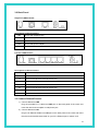
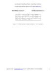
3.1 Front Panel Indicators and Description
Front panel of ADSL router has LED indicators to display router’s operating status.
Single-Port ADSL Router
○
ADSL
○
○
○
○
DATA
LAN
USB
PWR
Descriptions of LED status
ADSL
DATA
LAN
When connection with Internet (ADSL Connected) is established, this LED will light up.
When this LED is flashing: NO ADSL physical connection
When router is transferring data between Internet and router, this LED will be flashing.
When connection 10/100MB with end user is established, this LED will light up. When
router is transferring data between router and end user, this LED will be flashing.
USB
When an active USB cable is connected with router, this LED will light up.
PWR
When an active power adapter is connected with router, this LED will light up.
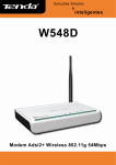
Four-Port ADSL Router
LAN
○
○
PWR
USB
○
○
○
○
○
4
3
2
1
ADSL
Descriptions of LED status
PWR
When an active power adapter is connected with router, this LED will light up.
USB
When an active USB cable is connected with router, this LED will light up.
4
When port 4 connection with end user is established, this LED will light up.
3
When port 3 connection with end user is established, this LED will light up.
2
When port 2 connection with end user is established, this LED will light up.
1
When port 1 connection with end user is established, this LED will light up.
ADSL
When connection with Internet (ADSL Connected) is established, this LED will light up.
When this LED is flashing: NO ADSL physical connection
8
3.2 Back Panel
Single-Port ADSL Router
LINE
USB
LAN
PWR
DEFAULT
Descriptions of All Connectors
LINE
Connect with telephone line.
USB
Connect with USB cable.
LAN
Connect with Ethernet Cable to Switch Hub or PC
PWR
Connect with power adapter
DEFAULT Reset button.
Four-Port ADSL Router
LINE
USB
1X
2X
3X
4X
PWR
DEFAULT
Descriptions of All Connectors
LINE
Connect with telephone line.
USB
Connect with USB cable.
1x
Connect with Ethernet Cable to Switch Hub.
2x
Connect with Ethernet Cable to Switch Hub.
3x
Connect with Ethernet Cable to Switch Hub.
4x
Connect with Ethernet Cable to Switch Hub.
PWR
DEFAULT
Connect with power adapter.
Reset button.
3.3 Connect Related Devices
1) Connect Router to LINE
Plug the provided RJ-11 cable into LINE port on the back panel of the router and
insert the other end into splitter or wall phone jack.
2) Connect Router to LAN
Plug RJ-45 Ethernet Cable into LAN port on the back panel of the router and insert
the other end of the Ethernet Cable on your PC’s Ethernet port or switch / hub.
9
3) Connect Router to Power Adapter
Plug power adapter to PWR port on the back panel of the router and the other end to
a power outlet.
The diagram below illustrates a connection example,
Warning! Only use the power adapter provided in the package, otherwise it may cause
hardware damage.
10
4. Connecting ADSL Router via Ethernet and USB
You can connect this ADSL Router with PC through Ethernet cable or USB cable. After
connect is established, you can configure the host PC to be a DHCP client. You have to repeat
the same steps for every host PC on your network if you user DHCP function on your router.
4.1 Setup ADSL router via Ethernet Cable
If there is an available LAN card present on your PC, you just simply connect ADSL
router and PC through the Ethernet cable. Once you establish Internet connection, you could
browse the Web through the Ethernet cable.
4.2 Setup ADSL router via USB Cable
You can connect ADSL router with PC via USB cable when there is no LAN Card present
on your PC. USB cable acts as another LAN connection in this scenario. Once you establish
Internet connection, you could browse the Web through the USB cable.
USB Device Driver Installation for Windows OS (Win98SE/ME/2000/XP)
Step 1: Connect ADSL Router and PC with USB cable.
Step 2: Once “Found New Hardware Wizard” window pop out, click “Cancel”.
11
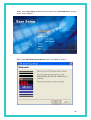
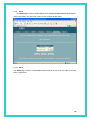
Step 3: Insert “Easy Setup” Software kit CD, and then click “Install USB Driver” to begin
device driver installation.
Step 4: After “DSL Modem Setup Wizard” shows, click “Next” to continue.
12
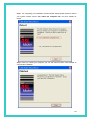
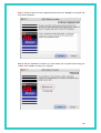
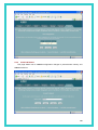
Step 5: Please review the following license agreement, and click “Accept” to continue.
Step 6: Waiting for few seconds for device driver installation.
13
Step 7: For completing your installation, the DSL Modem Setup Wizard requires to reboot
your system. Please choose “Yes, reboot the computer now” and click “Close” for
reboot.
Step 8: After you restart your computer, you can see Finish windows. Click “Finish” to
compete the installation.
14
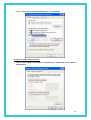
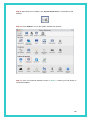
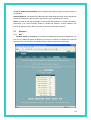
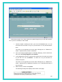
Step 9: Follow the procedures below to check if DSL router is properly installed.
Right-click “My Computer” on the desktop Æ Choose “Properties” Æ Select
“Hardware” tab Æ Click “Device Manager” button.
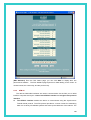
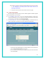
4.3 TCP/IP Configuration
For Windows XP
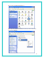
Step 1: Click Start and then select Control Panel in the main window screen.
15
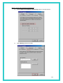
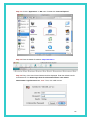
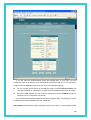
Step 2: Double-Click Network Connections icon.
Step 3: Right-click Local Area Connection (local network your ADSL hooked up with)
and then select “Properties”.
16
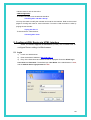
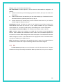
Step 4: Select Internet Protocol (TCP/IP) then click “Properties”.
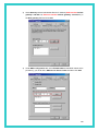
Configure IP address Automatically:
Step 5: Select Obtain an IP address automatically & Obtain DNS server address
automatically.
17
Configure IP address Manually:
Step 5: Select Use the following IP address & Use the following DNS server
addresses.
IP address: Fill in IP address 192.168.1.x. (x is a number between 3 to 254).
Subnet Mask: Default value is 255.255.255.0.
USB interface Default gateway: Default value is 192.168.1.2.
Ethernet interface Default gateway: Default value is 192.168.1.1
Preferred DNS server: Fill in preferred DNS server IP address.
Alternate DNS server: Fill in alternate DNS server IP address.
You can use ping command under DOS prompt to check if you have setup TCP/IP
protocol correctly and if you computer has successfully connected to this router.
For example, USB interface ping to the gateway
* Type ping 192.168.1.2 under DOS prompt and the following message will appear:
Pinging 192.168.1.2 with 32 bytes of data:
Reply from 192.168.1.2: bytes=32 times<1ms TTL=64
Reply from 192.168.1.2: bytes=32 times<1ms TTL=64
Reply from 192.168.1.2: bytes=32 times<1ms TTL=64
Reply from 192.168.1.2: bytes=32 times<1ms TTL=64
18
If the communication link between your computer and router is not setup correctly,
after your type ping 192.168.1.2 under DOS prompt following message will appear.
Pinging 192.168.1.2 with 32 bytes of data:
Request timed out.
Request timed out.
Request timed out.
Request timed out.
This failure might be caused by cable issue or something wrong in configuration
procedure.
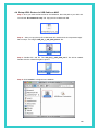
For Windows 2000
Step 1: Right-click My Network Places and select Properties in the main windows
screen.
Step 2: Right-click Local Area Connection (your local network hooked up with DSL
Router) and select Properties.
19
Step 3: Select Internet Protocol (TCP/IP) then click Properties.
20
Configure IP Automatically:
Step 4: Select Obtain an IP address automatically and Obtain DNS server address
automatically then click OK to complete IP configuring process.
Configure IP Manually:
Step 4: Select Use the following IP address and Use the following DNS server
addresses.
21
IP address: Fill in IP address 192.168.1.x. (x is a number between 3 to 254).
Subnet Mask: Default value is 255.255.255.0.
USB interface Default gateway: Default value is 192.168.1.2.
Ethernet interface Default gateway: Default value is 192.168.1.1
Preferred DNS server: Fill in preferred DNS server IP address.
Alternate DNS server: Fill in alternate DNS server IP address.
For Windows 98SE/ME
Step 1: Click Start then Settings and choose Control Panel
Step 2: Double click Network icon.
Step 3: Select Configuration tab, then choose TCP/IP from the list of installed network
Components and click Properties button.
Step4: You can setup the following configurations in two methods:
22
Option1: Get an IP from Router Automatically
1)
Choose Obtain an IP address automatically option in the next window.
2)
Select Gateway tab and click OK
23
3)
Select DNS Configuration tab and select Disable DNS then click OK
Option2: Configure IP Manually
1) Select Specify an IP address, set default IP address for the Router is
192.168.1.2, so use 192.168.1.X (X is a number between 3 to 254) for IP
Address field and 255. 255. 255.0 for Subnet Mask field.
24
2) Select Gateway tab and add default Router IP Address (USB interface default
gateway: 192.168.1.2, Ethernet interface default gateway: 192.168.1.1) in
the New gateway field and click Add.
3) Under DNS Configuration tab, select Enable DNS and add DNS values which
provides by your local ISP in DNS Server Search Order field then click Add.
25
4.4 Setup ADSL Router via USB Cable on MAC
Step 1: Once you insert the Device Driver CD-ROM disk, direct the path of your MAC OS.
You will see “DO-407952-LS-3.zip” file. Copy this file to Macintosh HD.
Step 2: After you copy the zip file to Macintosh HD, double-click the compressed “.zip”
file to unzip it. You will get “IAD_Rel_1_02E_PKG_004.sit” file.
Step 3: Double-click “.sit” file. The “IAD_Rel_1_02E_PKG_004.1” file will be created.
Double-click the created file again to open it.
Step 4: Click “Installer” to begin driver installation
26
Step 5: The ADSL Modem Installer window will be shown. Click “Next” to continue.
Step 6: Enter your Name and password for your system. Then, click “OK” to continue.
27
Step 7: Please review the License Agreement below and click “Accept” if you agree with
the license agreement.
Step 8: After the installation is finished, you must restart your computer before using your
modem. Click “Finish” to restart your computer.
28
Step 9: After restart your computer, click “System Preferences” on the bottom of the
desktop.
Step 10: Click “Network” icon on the System Preferences windows.
Step 11: Once your Ethernet Adapter’s button is “Green”, it means your DSL Router is
successful installed.
29
Step 12: Fill in TCP/IP IP Address:
IP address: Fill in IP Address 192.168.1.x. ( x is a number between 3 to 254).
Subnet Mask: Default value is 255.255.255.0.
Router: Default value is 192.168.1.2. (for USB cable installation)
30
Step 13: Choose “Application” on GO menu. Double-click “Internet Explorer”.
Step 14: Enter the default IP address: http://192.168.1.2
Step 15: Entry of the User ID and Password will be displayed. Enter the default User ID
and Password. The default login User ID of the administrator & the default
administrator login Password are “root”. Then, click “OK” to enter.
31
Step 16: DSL Router Webpage will show as below:
4.5 Setup ADSL Router via USB Cable on Linux
This driver supports Linux-2.4 kernel.
Compiling the Driver
To compile the driver simply run make in "viking" directory. This will create binary driver
with name VKGEther.
% make
Loading the module
To load the VKGEther module enter the following command as root in directory "viking"
Syntax:
% insmod ./VKGEther {Module Options}
Unloading the module
To unload an unused module:
% rmmod VKGEther
You will need to exit or disconnect any program currently using the module before it
unload. If the module was configured for LAN, shutdown the ethernet interface:
% ifconfig eth1 down
The ethernet interface associated with the VKGEther driver was "eth1" that's why
32
interface name is eth1 in above line.
LAN Configuration
To enable LAN traffic over the ethernet interface:
% ifconfig eth1 192.168.1.200 up
You may also need to modify the netmask and route for the interface. Refer to the manual
pages for ifconfig and route for more information. To test the LAN connection is alive by
pinging the remote side:
% ping 192.168.1.1
To disconnect the LAN interface:
% ifconfig eth1 down
5. Configure ADSL Router via HTML Interface
ADSL II+ Router supports a web-based (HTML) GUI to allow user to
configure Router setting via Web browser.
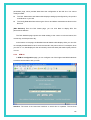
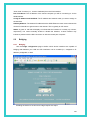
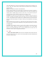
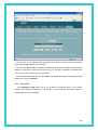
5.1 Login
1)
Launch the Web browser.
2)
Enter the default IP Address: http://192.168.1.1
3)
Entry of the User Name and Password will be displayed. Enter the default login
User Name and Password. The default login User Name of the administrator is root,
and the default admin login password is root.
33
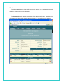
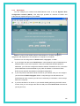
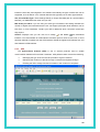
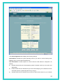
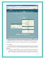
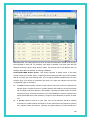
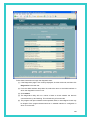
5.2 Home
The Home page displays when you first access the program or, if another tab is already
displaying, when you click on the Home tab.
5.2.1
Home
The System View table provides a snapshot of the device configuration. Note that some
of the settings are links to the software pages that enable you to configure those settings.
34
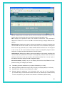
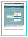
Device: Displays basic information about the device hardware and software versions, the
system uptime since the last reboot, and the preconfigured operating mode.
DSL: Displays the operational status, DSL standard conformance, and performance
statistics for the DSL line. You can click DSL in the table heading to display additional DSL
settings.
WAN Interfaces: Displays the software name(s) and settings for the device interfaces that
communicate with the ISP via DSL, such as a PPP, EOA, or IPoA interface. Although the
device has one physical DSL port, multiple software-defined interfaces can be configured
to use it. You can click on the interface names to view the Configuration pages for these
interfaces, or display the Advanced task bar for similar options.
LAN Interfaces: Displays the software names and settings for the device interfaces that
communicate directly with the local network. These typically include at least one Ethernet
interface, named eth-0, and may include a USB interface named usb-0. You can click on
the interface names to display the LAN Configuration page.
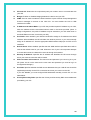
Services Summary: Displays any of the following services that ADSL/Ethernet router
performs to help you manage your network:
z
Translating private IP addresses to your public IP address (5.7.1-NAT).
z
Setting up filtering rules that accept or deny incoming or outgoing data (5.7.4-IP Filter).
z
Enabling router-to-router communication (5.7.2-RIP).
z
Enabling dynamic assignment of IP information from your ISP to your computers
(5.3.4-DHCP relay), from the device's built-in server to your network (5.3.3-DHCP Server)
or from a computer on your network to the device's LAN interface (DHCP Client).
35
Message forwarding based on the Internet Group Management Protocol (IGMP, not
z
configurable).
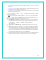
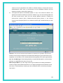
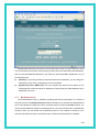
5.2.2
System Mode
The System Mode page enables you to configure system-level operating modes that use
bridging in addition or instead of routing protocols. You can also configure a feature in which
the mode is selected automatically at start-up, based on the type of Internet connection
detected on the LAN PC(s).
The current system mode is shown on the System View page that displays when you
access the configuration program. The system mode is not configured using a single setting.
Rather, it is determined at system startup based on whether the device's LAN and WAN
interfaces are configured with IP information (i.e., are "IP-enabled"), and whether the Bridging
setting on the System Mode page is enabled or disabled.
z
When the Bridging setting on the System Mode page is disabled, then the system mode
will display as "Routing".
z
When the Bridging setting is enabled and at least one LAN or WAN interface is
IP-enabled, then the system mode will display as "Routing and Bridging."
z
When the Bridging setting is enabled and no interfaces are IP enabled, then the device is
considered to be in Bridging Mode. Note, however, that in this case you would not be
able to access Configuration Manager; without being IP-enabled, the Ethernet interface
could not communicate using the Internet protocol HTTP, which is used to display
information in your Web browser.
36
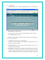
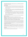
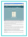
5.2.3
Quick Configuration
The Quick Configuration displays the settings you are most likely to need to change
when you first set up your ADSL/Ethernet router. Work with your ISP to determine the values
or settings you need to change. NOTE: It is a strong recommendation that using Quick
Configuration to set your ADSL settings.
z
ATM Interface: Selects the ATM interface you want to use (usually 0). Your system may
be configured with more than one ATM interface if you are using different types of
services with your ISP.
z
Operation Mode: Enables or disables the device. When set to "Disabled", the device
cannot be used to provide Internet connectivity or routing services for your network.
z
Encapsulation: Determines the type of data link used to communicate with your ISP.
37
z
VPI and VCI: Determine the unique data path your modem uses to communicate with
your ISP.
z
Bridge: Enables or disables bridging between the device and your ISP.
z
IGMP: Can be used to enable the WAN interface to pass Internet Group Management
Protocol messages it receives to the LAN PCs. You must enable the LAN or USB
interfaces for IGMP.
z
IP Address and Subnet Mask: If your ISP has provided a public IP address to your LAN,
enter the address and the associated subnet mask in the boxes provided. (Note: In
bridge configurations, the public IP address may be entered on your PC rather than on
the ADSL/Ethernet router; check with your ISP.).
z
Use DHCP: When enabled, your ISP will use DHCP to assign an IP address to the WAN
interface. When disabled, the ISP will either use another protocol, or you must manually
assign an IP address to it. See the appropriate WAN interface help topic for PPP or EoA
interfaces.
z
Default Route: When enabled, specifies that the WAN interface specified above will be
used as the default route for your LAN. Whenever one of your LAN computers attempts
to access the Internet, the data will be sent via through this interface.
z
Gateway IP Address: Specifies the IP address that identifies the ISP server through
which your Internet connection will be routed.
z
PPP Username and Password: The username and password you use to log in to your
ISP. (Note: this is not the same as the user name and password you used to log in to
Configuration Manager.)
z
Use DNS: Specifies whether the DNS server addresses that your LAN will use should be
supplied dynamically via the PPP connection each time you connect to the ISP.
If you click Disable, you must configure DNS addresses manually on each PC or in the
fields below.
z
Primary/Secondary DNS: Specifies the Primary and Secondary DNS server addresses
provided by your ISP.
38
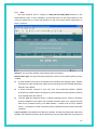
5.3
LAN
5.3.1
LAN Configuration
Use this page to set the LAN configuration, which determines how your device is
identified on the network.
The LAN Configuration table displays the following settings:
z
System Mode: Identifies the system operating mode for your device, such as Routing
mode, Bridging mode, or both modes simultaneously. See Configuring the System Mode
for more information).
z
Get LAN Address: Provides options for how the device's LAN interface is assigned an
IP address:
39
-- Manual indicates that you will be assigning a static IP address, which you can enter in the
fields below.
-- External DHCP Server indicates that your ISP will be assigning an IP address from their
own DHCP servers, dynamically each time you log on.
-- Internal DHCP Server indicates that you have a DHCP server device on your network that
will assign an address to the port.
If you choose either the internal or external server option, the LAN interface is called a
DHCP client of the server.
Note that the public IP address assigned to you by your ISP is not your LAN IP address.
The public IP address identifies the WAN (ADSL) port on your ADSL/Ethernet router to the
Internet. Or, in bridge configurations, it may be assigned to a PC.
z
Speed/Duplex: Speed indicates the speed of the Ethernet communication between the
ADSL/Ethernet router and the LAN PCs or hub. Duplex indicates the type of Ethernet
communication (i.e., full duplex, or half-duplex). These settings are not
user-configurable.
z
LAN IP Address and Network Mask: The IP address and network mask for the port.
z
IGMP: Indicates whether this interface is enabled with the Internet Group Management
Protocol. When enabled, the ADSL/Ethernet router collects and consolidates requests
from the LAN PCs to receive IGMP messages from external computers. The interface
also forwards IGMP messages it receives on its WAN interface to the appropriate hosts.
The WAN interface must also be enabled for the IGMP protocol.
z
MTU: The Maximum Transmission Unit specifies the size in bytes of the largest Ethernet
packet that the interface will accept. Packets larger than this size will be dropped.
40
5.3.2
DHCP Mode
You can configure your network and ADSL/Ethernet router to use the Dynamic Host
Configuration Protocol (DHCP). This help topic provides an overview of DHCP and
instructions for implementing it on your network.
DHCP is a protocol that enables network administrators to centrally manage the
assignment and distribution of IP information to computers on a network.
The device can be configured as a DHCP server, relay agent, or client.
z
If you configure the device as a DHCP server, it will maintain the pool of addresses and
distribute them to your LAN computers. If the pool of addresses includes private IP
addresses, you must also configure the Network Address Translation service, so that the
private addresses can be translated to your public IP address on the Internet. Both
DHCP server and NAT are enabled in the default configuration.
z
If your ISP performs the DHCP server function for your network, then you can configure
your device as a DHCP relay agent. When a computer logs onto the network, the
ADSL/Ethernet router contacts your ISP for the necessary IP information, which it relays
back to the computer.
z
If you have another PC or device on your network already performing the DHCP server
function, then you can configure the device's LAN port to be a DHCP client of that server
(as are your PCs).
41
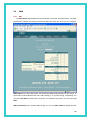
5.3.3
DHCP Server
This topic describes how to configure the DHCP server feature on your ADSL/Ethernet
router.
Adding DHCP Server Address Pools:
1. If the DHCP Server Configuration page is not already displaying, click the LAN tab, and
then click DHCP Server in the task bar.
Depending on your pre-configured settings, the table may display up to two address pools,
each in a row, or may be empty.
2.
Click Add. The DHCP Server Pool - Add page displays.
3. Enter values for the Start IP Address, End IP Address, and Net Mask fields, which are
required, and any others as needed:
z
Start/End IP Addresses: Specify the lowest and highest addresses in the pool, up to a
maximum range of 254 addresses.
z
Mac Address: A MAC address is a manufacturer-assigned hardware ID that is unique
for each device on a network. Use this field only if you want to assign a specific IP
address to a specific computer (that is, you are creating an exception to the dynamic
assignment of addresses). The IP address you specify will be assigned to the computer
42
that corresponds to this MAC address. If you type a MAC address here, you must have
specified the same IP address in both the Start IP Address and End IP Address fields.
Net Mask: Specifies which portion of each IP addresses in this range refers to the
z
network and which portion refers to the host (computer). You can use the net mask to
distinguish which pool of addresses should be distributed to a particular subset of
computers on your LAN (call a subnet).
Domain Name: A user-friendly name that refers to the subnet that includes the
z
addresses in this pool.
Gateway Address: The address of the default gateway for computers that receive IP
z
addresses from this pool. If no value is specified, then the appropriate LAN (eth-0) or
USB (usb-0) port address on the device will be distributed to each PC as its gateway
address, depending on how each is connected. See Configuring IP Routes for an
explanation of gateway addresses.
DNS/SDNS: The IP address of the Domain Name System server to be used by
z
computers that receive IP addresses from this pool. The DNS translates common
Internet names that you type into your web browser into their equivalent numeric IP
addresses. Typically, this server is located with your ISP.
SMTP...SWINS (optional): The IP addresses of devices that perform various services for
z
computers that receive IP addresses from this pool (such as the SMTP, or Simple Mail
Transfer Protocol, server which handles e-mail traffic). Contact your ISP for these
addresses.
4.
When you are done defining the pool, click Submit.
A confirmation page displays briefly to indicate that the pool has been added successfully.
After a few seconds, the DHCP Server Pool – Add page displays with the newly added pool.
5. Click DHCP Mode in the task bar, then follow the instructions in Setting the DHCP Mode to
enable the DHCP server.
5.3.4
DHCP Relay
Some ISPs perform the DHCP server function for their customers' home/small office
networks. In this case, you can configure the device as a DHCP relay agent. When a
computer on your network requests Internet access, the ADSL/Ethernet router connects your
ISP to obtain an IP address and other information, and then forwards that information to the
computer.
43
Follow these instructions to configure DHCP relay:
First, you must configure each LAN computer to receive IP information assigned by a
DHCP server:
1) Open the Windows Control Panel and display the computer's Networking properties.
Configure the TCP/IP properties to "Obtain an IP address automatically" (the actual text may
vary depending on your operating system).
Next, you specify the IP address of the DHCP server and select the interfaces on your network
that will be using the relay service.
2) If the DHCP Configuration page is not already displaying, click the LAN tab, and then click
DHCP Relay in the task bar.
3) In the DHCP Server Address fields, type the IP address of your ISP's DHCP server.
If you do not have this address, it is not essential to enter it here. Requests for IP information
from your LAN will be passed to the default gateway, which should route the request
appropriately.
44
4) Select your WAN interface from the drop-down list and click Add.
The WAN interface may be named ppp-0, eoa-0, or ipoa-0. Contact your ISP if you are
unsure which type to use.
(Note that you can delete an interface from the table by clicking
in the right column.)
5) Click Submit. A page displays to confirm your changes, and the program returns to the
DHCP Relay Configuration page.
6) Click DHCP Mode in the task bar, then follow the instructions in Setting the DHCP Mode to
enable DHCP relay.
NOTE: If want your changes to be permanent, be sure to commit them.
45
5.4
WAN
5.4.1
DSL
The DSL Status page displays current information on the DSL line performance. The page
refreshes according to the setting in the Refresh Rate drop-down list, which you can configure.
[DSL Status] In the DSL Status table, the Operational Status setting displays a red, orange, or
green ball to indicate that the DSL line is idle, starting up, or up-and-running, respectively. You
can click Loop Stop to end the DSL connection. To restart the connection, you can click Loop
Start.
[DSL Parameters] From the DSL Status Page, you can click DSL Param to display the DSL
46
parameters page, which provides data about the configuration of the DSL line. You cannot
modify this data.
The DSL Parameters and Status table displays settings preconfigured by the product
z
manufacturer or your ISP.
The Config Data table lists various types of error and defect measurements found on the
z
DSL line.
[DSL Statistics] From the DSL Status page, you can click Stats to display DSL line
performance statistics.
The DSL Statistics page reports error data relating to the current 15 minute interval, the
current day, and the previous day.
At the bottom of the page, the Detailed Interval Statistic table displays links you can click
on to display detailed data for each 15 minute interval in the past 24 hours. For example, when
you click on 1-4, data displays for the 16 intervals (15-minutes each) that make up the previous
4 hours.
5.4.2
ATM VC
In ATM VC configuration page, you can configure one of the higher level WAN interfaces
to enable communication with your ISP.
Interface: The name of the lower-level interface on which this VC operates. The low-level
47
interface names are preconfigured in the software and identify the type of traffic that can be
supported, such as data or voice. Internet data services typically use an AAL5-type interface.
VPI, VCI, and Mux Type: These settings identify a unique ATM data path for communication
between your ADSL/Ethernet router and your ISP
Max Proto per AAL5: If you are using an AAL5-type of interface, this setting indicates the
number of higher level interfaces that the VC can support (the higher level interfaces can be
PPP, EoA, or IPoA interfaces). Contact your ISP to determine which connection protocol(s)
they require.
Actions: Displays icons you can click on to modify (
) and delete (
) the associated
interface. You cannot delete an ATM interface if another protocol such as PPP, EoA, or IPoA
has been defined to operate over the ATM interface. Delete the higher-level interface first, and
then delete the ATM interface.
5.4.3
PPP
The Point-to-Point Protocol (PPP) is one of several protocols used to enable
communication between ISPs and their customers. PPP performs tasks such as the following:
¾
Identifying the type of service the ISP provides to a given customer.
¾
Identifying the customer to the ISP through a username and password login.
¾
Enabling the ISP to assign Internet information to the customer's computers.
48
You can configure the following settings on the PPP Configuration page:
Inactivity TimeOut...: The time in minutes that must elapse before a PPP connection
times-out due to inactivity. This setting applies only to PPP interfaces that are configured as
"start-on-data" interfaces. This type of interface starts up only when it receives data, and then
returns to a down state after the specified amount of time. This setting works with the following
setting to determine what type of data can activate a start-on-data interface.
Ignore WAN to LAN traffic...: When enabled, data traffic traveling in the incoming direction -from a WAN interface to the LAN interface -- will not count as activity on the WAN port for the
purposes of determining whether to make it inactive; i.e., WAN to LAN traffic will not activate a
start-on-data interface. Only LAN-to-WAN traffic will start the interface.
The PPP Configuration table displays the following fields:
Interface: The predefined name of the PPP interface.
VC: The Virtual Circuit over which this PPP data is sent. The VC identifies the physical path
the data takes to reach your ISP.
Interface Sec Type: The type of Firewall protections that are in effect on the interface (public,
private, or DMZ):
z
A public interface connects to the Internet (PPP interfaces are typically public). Packets
received on a public interface are subject to the most restrictive set of firewall protections
defined in the software.
z
A private interface connects to your LAN, such as the Ethernet interface. Packets
received on a private interface are subject to a less restrictive set of protections, because
they originate within the network.
z
The term DMZ (de-militarized zone), in Internet networking terms, refers to computers
that are available for both public and in-network accesses (such as a company's public
Web server). Packets incoming on a DMZ interface -- whether from a LAN or external
source -- are subject to a set of protections that is in between public and private
interfaces in terms of restrictiveness.
Protocol: The type of PPP protocol used. Your ISP may use PPP-over-Ethernet (PPPoE) or
PPP-over-ATM (PPPoA).
WAN IP: The IP address currently assigned to your WAN (DSL) port by your ISP.
Gateway IP: The IP address of the server at your ISP that provides you access to the Internet.
Default Route: Indicates whether the ADSL/Ethernet router should use the IP address
assigned to this connection as its default route. Can be Enabled or Disabled.
Use DHCP: When set to Enable, the device will acquire additional IP information from the
ISP's DHCP server. The PPP connection itself acquires the device's IP address, mask, DNS
address, and default gateway address. With Use DHCP enabled, the device will acquire IP
addresses for various other server types (WINS, SMTP, POP3, etc. -- these server types are
49
listed on the DHCP Server Configuration page).
Use DNS: When set to Enable, the DNS address learned through the PPP connection will be
distributed to clients of the device's DHCP server. This option is useful only when the
ADSL/Ethernet Router is configured to act as a DHCP server for your LAN. When set to
Disable, LAN hosts will use the DNS address(es) pre-configured in the DHCP pool and in the
DNS feature.
Oper. Status: Indicates whether the link is currently up or down or if a specific type of data
exchange is under way (e.g., password authorization or DHCP).
Action(s): Provides icons you can click on to modify (
details on (
5.4.4
), delete (
), or view additional
) the PPP interface.
EDA
This topic describes how to configure an Ethernet-over-ATM (EoA) interface on the
ADSL/Ethernet router, if one is needed to communicate with your ISP. This interface is also
commonly referred to as an RFC1483 interface, for the name of the Internet specification to
which it conforms.
Interface: The name the software uses to identify the EoA interface.
Interface Sec Type: The type of security protections in effect on the interface (public, private,
or DMZ):
z
A public interface connects to the Internet (PPP interfaces are typically public). Packets
received on a public interface are subject to the most restrictive set of firewall protections
50
defined in the software.
z
A private interface connects to your LAN, such as the Ethernet interface. Packets
received on a private interface are subject to a less restrictive set of protections, because
they originate within the network.
z
The term DMZ (de-militarized zone), in Internet networking terms, refers to computers
that are available for both public and in-network accesses (such as a company's public
Web server). Packets incoming on a DMZ interface -- whether from a LAN or external
source -- are subject to a level of protection that is in between those for public and private
interfaces.
Lower interface: EoA interfaces are defined in software, and then associated with lower-level
software and hardware structures (at the lowest level, they are associated with a physical port
- the WAN port). This field should reflect an interface name defined in the next lower level of
software over which the EoA interface will operate. This will be an ATM VC interface, such as
aal5-0.
Config IP Address and Net Mask: The IP address and network mask you want to assign to
the interface. If the interface will be used for bridging with your ISP and you will not be using
the device as a router on your LAN, then you do not need to specify IP information. If you
enable DHCP for this interface, then the Configured IP address will serve only as a request to
the DHCP server. The actual address that is assigned by the ISP may differ if this address is
not available.
Use DHCP: When enabled, this setting instructs the device to accept IP information assigned
dynamically by your ISP's DHCP server. If the interface will be used for bridging with your ISP
and you will not be routing data through it, leave this checkbox unselected.
Default Route: Indicates whether the ADSL/Ethernet router should use the IP address
assigned to this interface, if any, as its default route for your LAN. This can be Enable or
Disable.
Gateway Address: The external IP address that the ADSL/Ethernet router communicates with
via the EoA interface to gain access to the Internet. This is typically an ISP server.
Status: A green or red ball will display to indicate that the interface is currently up or down,
respectively. You cannot manually enable or disable the interface; a down interface may
indicate a problem with the DSL connection or the connection to the ISP's access server.
Action: Icons you can click on to edit (
) or delete (
) the associated EoA interface.
51
5.4.5
IPOA
This topic describes how to configure an IPoA (Internet Protocol over ATM) interface on
the ADSL/Ethernet router.
Interface: The name the software uses to identify the IPoA interface.
Interface Security Type: The type of firewall protections that are in effect on the interface
(public, private, or DMZ):
z
A public interface connects to the Internet (IPoA interfaces are typically public). Packets
received on a public interface are subject to the most restrictive set of firewall protections
defined in the software.
z
A private interface connects to your LAN, such as the Ethernet interface. Packets
received on a private interface are subject to a less restrictive set of protections, because
they originate within the network.
z
The term DMZ (de-militarized zone), in Internet networking terms, refers to computers
that are available for both public and in-network accesses (such as a company's public
Web server). Packets incoming on a DMZ interface -- whether from a LAN or external
source -- are subject to a level of protection that is in between public and private
interfaces in terms of restrictiveness
RFC 1577: Specifies whether the IPoA protocol to be used complies with the IEFT
specification named "RFC 1577 - Classical IP and ARP over ATM" (contact your ISP if unsure).
Lower interface: An IPoA interface must be associated with one or more ATM VCs that have
been defined on the system. The ATM VC is also considered an interface--one that performs
52
"lower level" functions (i.e., closer to hardware) than the IPoA interface.
Peer IP Address: The IP address of the remote computer you will be connecting to via the
WAN interface.
Config IP Address and Net Mask: The IP address and network mask you want to assign to
the interface.
Gateway Address: The external IP address that the ADSL/Ethernet router communicates with
via the IPoA interface to gain access to the Internet. This is typically an ISP server.
Status: A green or red ball will display to indicate that the interface is currently up or down,
respectively. You cannot manually enable or disable the interface; a down interface may
indicate a problem with the DSL connection or with the remote peer computer.
5.5
Bridging
5.5.1
Bridging
Use the bridge configuration page to define which device interfaces are capable of
bridging data between your LAN and ISP. Interfaces can be routable (i.e., assigned an IP
address), bridgeable, or both.
Enabling the device to function as a bridge requires two steps:
53
[Enabling Bridgeable Interfaces]
To enable bridging, you use the Bridge Configuration page to specify the interfaces that
can bridge data. Then, you use the System Mode page to enable the appropriate operating
mode.
1. If the Bridge Configuration page is not already displaying, click the Bridging tab.
The Bridge Configuration Page displays by default.
The page displays Enable/Disable links for Bridging, WAN-to-WAN Bridging, and Zero
Installation PPP bridge (ZIPB). The page also provides a table for specifying the interfaces on
which bridging will be performed. The table may be empty if bridging has not yet been
configured.
2. Select the interface names on which you want to perform bridging and click Add.
[Enabling Bridging Services]
After configuring the bridgeable interfaces, click one of the following links on the Bridge
Configuration Page:
• Bridging: Enable/Disable
• WAN to WAN Bridging: Enable/Disable
• ZIPB: Enable Disable
Each of the links displays the System Mode Page, where you can enable the appropriate
bridging operating mode.
5.5.2
LAN Configuration
This topic allows user to configure the interfaces on the ADSL/Ethernet router that
communicate with your LAN and USB computers.
54
The LAN Configuration table displays the following settings:
System Mode: Identifies the system operating mode for your device, such as Routing mode,
Bridging mode, or both modes simultaneously.
Get LAN Address: Provides options for how the device's LAN interface is assigned an IP
address.
z
Manual indicates that you will be assigning a static IP address, which you can enter in the
fields below.
z
External DHCP Server indicates that your ISP will be assigning an IP address from their
own DHCP servers, dynamically each time you log on.
z
Internal DHCP Server indicates that you have a DHCP server device on your network
55
that will assign an address to the port.
If you choose either the internal or external server option, the LAN interface is called a
DHCP client of the server.
Note that the public IP address assigned to you by your ISP is not your LAN IP address.
The public IP address identifies the WAN (ADSL) port on your ADSL/Ethernet router to the
Internet. Or, in bridge configurations, it may be assigned to a PC.
Speed/Duplex: Speed indicates the speed of the Ethernet communication between the
ADSL/Ethernet router and the LAN PCs or hub. Duplex indicates the type of Ethernet
communication (i.e., full duplex, or half-duplex). These settings are not user-configurable
LAN IP Address and Network Mask: The IP address and network mask for the port.
IGMP: Indicates whether this interface is enabled with the Internet Group Management
Protocol. When enabled, the ADSL/Ethernet router collects and consolidates requests from
the LAN PCs to receive IGMP messages from external computers. The interface also forwards
IGMP messages it receives on its WAN interface to the appropriate hosts. The WAN interface
must also be enabled for the IGMP protocol.
MTU: The Maximum Transmission Unit specifies the size in bytes of the largest Ethernet
packet that the interface will accept. Packets larger than this size will be dropped.
5.5.3
DSL
You can view configuration parameters and performance statistics for the ADSL/Ethernet
Router's DSL line. If the DSL Status page is not already displaying, click the WAN tab. The
DSL page displays by default.
56
[DSL Status] The DSL Status page displays current information on the DSL line performance.
The page refreshes according to the setting in the Refresh Rate drop-down list, which you can
configure.
In the DSL Status table, the Operational Status setting displays a red, orange, or green ball
to indicate that the DSL line is idle, starting up, or up-and-running, respectively. You can click
Loop Stop to end the DSL connection. To restart the connection, you can click Loop Start.
57
[DSL Parameters] From the DSL Status Page, you can click DSL Param to display the DSL
parameters page, which provides data about the configuration of the DSL line. You cannot
modify this data.
58
[DSL Statistics] From the DSL Status page, you can click Stats to display DSL line
performance statistics. The DSL Statistics page reports error data relating to the current 15
minute interval, the current day, and the previous day.
5.5.4
ATM VC
The devices WAN-side interfaces are used to communication via the DSL port. A WAN
interface comprises two layers: a lower-level ATM VC interface and a higher-level protocol
interface:
z
The ATM VC interface enables the device to communicate using the Asynchronous
Transfer Mode protocol. The ATM protocol provides a common format for transmitting
data over a variety of hardware systems that make up the backbone of the Internet. The
59
virtual circuit (VC) properties of the ATM VC interface identify a unique path that your
ADSL/Ethernet router uses to communicate via the ATM-based network with the
telephone company central office equipment.
z
The higher-level protocol interface(s) operate "on top" of the ATM VC interface. The
higher-level interface handles the protocols needed to log onto and exchange data with
the ISP's access server. ISPs can use several different protocols, including the
Point-to-Point Protocol (PPP), Ethernet-over-ATM (EoA) protocol, or the Internet
Protocol-over-ATM (IPoA). Be sure to create the specific type of WAN interface your ISP
requires.
Interface: The name of the lower-level interface on which this VC operates. The low-level
interface names are preconfigured in the software and identify the type of traffic that can be
supported, such as data or voice. Internet data services typically use an AAL5-type interface.
Vpi, Vci, and Mux Type: These settings identify a unique ATM data path for communication
between your ADSL/Ethernet router and your ISP
Max Proto per AAL5: If you are using an AAL5-type of interface, this setting indicates the
number of higher level interfaces that the VC can support (the higher level interfaces can be
PPP, EoA, or IPoA interfaces). Contact your ISP to determine which connection protocol(s)
they require.
Actions: Displays icons you can click on to modify (
) and delete (
) the associated
interface. You cannot delete an ATM interface if another protocol such as PPP, EoA, or IPoA
has been defined to operate over the ATM interface. Delete the higher-level interface first, and
then delete the ATM interface.
60
5.5.5
RFC 1483 Interface (EoA)
The Ethernet-over-ATM (EoA) protocol is commonly used to carry data between local
area networks that use the Ethernet protocol and wide-area networks that use the ATM
protocol. Many telecommunications industry networks use the ATM protocol. ISPs who provide
DSL services often use the EoA protocol for data transfer with their customers' DSL modems.
EoA can be implemented to provide a bridged connection between a DSL modem and the ISP.
In a bridged connection, data is shared between the ISP's network and their customer's as if
the networks were on the same physical LAN. Bridged connections do not use the IP protocol.
EoA can also be configured to provide a routed connection with the ISP, which uses the IP
protocol to exchange data.
Interface: The name the software uses to identify the EoA interface.
Interface Sec Type: The type of security protections in effect on the interface (public, private,
or DMZ):
z
A public interface connects to the Internet (IPoA interfaces are typically public). Packets
received on a public interface are subject to the most restrictive set of firewall protections
defined in the software.
z
A private interface connects to your LAN, such as the Ethernet interface. Packets
received on a private interface are subject to a less restrictive set of protections, because
they originate within the network.
z
The term DMZ (de-militarized zone), in Internet networking terms, refers to computers
61
that are available for both public and in-network accesses (such as a company's public
Web server). Packets incoming on a DMZ interface -- whether from a LAN or external
source -- are subject to a level of protection that is in between those for public and private
interfaces.
Lower interface: EoA interfaces are defined in software, and then associated with lower-level
software and hardware structures (at the lowest level, they are associated with a physical port
- the WAN port). This field should reflect an interface name defined in the next lower level of
software over which the EoA interface will operate. This will be an ATM VC interface, such as
aal5-0.
Config IP Address and Net Mask: The IP address and network mask you want to assign to
the interface. If the interface will be used for bridging with your ISP and you will not be using
the device as a router on your LAN, then you do not need to specify IP information. If you
enable DHCP for this interface, then the Configured IP address will serve only as a request to
the DHCP server. The actual address that is assigned by the ISP may differ if this address is
not available.
Use DHCP: When enabled, this setting instructs the device to accept IP information assigned
dynamically by your ISP's DHCP server. If the interface will be used for bridging with your ISP
and you will not be routing data through it, leave this checkbox unselected.
Default Route: Indicates whether the ADSL/Ethernet router should use the IP address
assigned to this interface, if any, as its default route for your LAN. This can be Enable or
Disable.
Gateway Address: The external IP address that the ADSL/Ethernet router communicates with
via the EoA interface to gain access to the Internet. This is typically an ISP server.
5.6
Routing
5.6.1
IP Route
IP routes can be created on the ADSL/Ethernet router to specify where it should send
data received on a particular interface. Routes specify the IP address of the next device
interface or Internet destination to forward data to, given the ultimate destination of the data.
A common type of route is a default gateway, which defines the IP address where all data
is forwarded unless an IP route has been defined for the particular destination in question.
Each time data is passed towards its destination from one Internet address to another, it is said
to complete one hop.
62
Destination: Specifies the IP address of the destination computer. The destination can
specified as the IP address of a specific computer or an entire network. It can also be specified
as all zeros to indicate that this route should be used for all destinations for which no other
route is defined (this is the route that creates the default gateway).
Netmask: Indicates which parts of the destination address refer to the network and which
parts refer to a computer on the network. The default gateway uses a netmask of 0.0.0.0.
NextHop: Specifies the next IP address to send data to when its final destination is that shown
in the destination column.
IfName: Displays the name of the interface through which to data is forwarded to the specified
next hop.
Route Type: Indicates whether the route is direct or indirect. In a direct route, the source and
destination computers are on the same network, and the router attempts to directly deliver the
data to the computer. In an indirect route, the source and destination computers are on
different networks, and the router forwards data to a device on another network for further
handling.
Route Origin: Displays how the route was defined. Dynamic indicates that the route was
predefined on the system by your ISP or the manufacturer. Routes you create are labeled
Local. Other routes may be created automatically (see Configuring RIP), or defined remotely
through various network management protocols (LCL or ICMP).
63
5.6.2
IP Address Table
The interfaces on your ADSL/Ethernet router that communicate with other network and
Internet devices are identified by unique Internet protocol (IP) addresses. You can use the
Configuration Manager to view the list of IP addresses that your device uses, and to view
other system and network performance data.
The IP Address table lists the IP addresses, network masks ("Net Mask"), and interface
names ("IF Name") for each of its IP-enabled interfaces.
5.6.3
LAN Configuration
This topic describes how to configure the interfaces on the ADSL/Ethernet router that
communicate with your LAN and USB computers.
64
If you are using the ADSL/Ethernet router with multiple PCs on your LAN, you must
connect the LAN via an Ethernet hub connected to the device's LAN port. If you are using a
single PC with the ADSL/Ethernet router, you have two connection options:
z
You can connect the PC directly to the LAN port using a cross-over Ethernet cable. See
your User's Manual for a description of cross-over and straight-through Ethernet cables.
z
If the PC is USB-enabled, you can connect it directly to the device's USB port. Only one
computer can be connected in this manner.
You can also use the USB and Ethernet interfaces simultaneously, connecting your LAN to
the Ethernet port and a standalone PC to the USB port.
System Mode: Identifies the system operating mode for your device, such as Routing mode,
65
Bridging mode, or both modes simultaneously.
Get LAN Address: Provides options for how the device's LAN interface is assigned an IP
address:
Manual indicates that you will be assigning a static IP address, which you can enter in the
z
fields below.
External DHCP Server indicates that your ISP will be assigning an IP address from their
z
own DHCP servers, dynamically each time you log on.
Internal DHCP Server indicates that you have a DHCP server device on your network
z
that will assign an address to the port.
Speed/Duplex: Speed indicates the speed of the Ethernet communication between the
ADSL/Ethernet router and the LAN PCs or hub. Duplex indicates the type of Ethernet
communication (i.e., full duplex, or half-duplex). These settings are not user-configurable.
LAN IP Address and Network Mask: The IP address and network mask for the port.
IGMP: Indicates whether this interface is enabled with the Internet Group Management
Protocol. When enabled, the ADSL/Ethernet router collects and consolidates requests from
the LAN PCs to receive IGMP messages from external computers. The interface also forwards
IGMP messages it receives on its WAN interface to the appropriate hosts. The WAN interface
must also be enabled for the IGMP protocol.
MTU: The Maximum Transmission Unit specifies the size in bytes of the largest Ethernet
packet that the interface will accept. Packets larger than this size will be dropped.
5.6.4
DSL
The DSL Status page displays current information on the DSL line performance. The page
refreshes according to the setting in the Refresh Rate drop-down list, which you can configure.
66
In the DSL Status table, the Operational Status setting displays a red, orange, or green ball
to indicate that the DSL line is idle, starting up, or up-and-running, respectively. You can click
Loop Stop to end the DSL connection. To restart the connection, you can click Loop Start.
5.6.5
ATM VC
The devices WAN-side interfaces are used to communication via the DSL port. A WAN
interface comprises two layers: a lower-level ATM VC interface and a higher-level protocol
interface:
z
The ATM VC interface enables the device to communicate using the Asynchronous
Transfer Mode protocol. The ATM protocol provides a common format for transmitting
data over a variety of hardware systems that make up the backbone of the Internet. The
67
virtual circuit (VC) properties of the ATM VC interface identify a unique path that your
ADSL/Ethernet router uses to communicate via the ATM-based network with the
telephone company central office equipment.
z
The higher-level protocol interface(s) operate "on top" of the ATM VC interface. The
higher-level interface handles the protocols needed to log onto and exchange data with
the ISP's access server. ISPs can use several different protocols, including the
Point-to-Point Protocol (PPP), Ethernet-over-ATM (EoA) protocol, or the Internet
Protocol-over-ATM (IPoA). Be sure to create the specific type of WAN interface your ISP
requires.
Interface: The name of the lower-level interface on which this VC operates. The low-level
interface names are preconfigured in the software and identify the type of traffic that can be
supported, such as data or voice. Internet data services typically use an AAL5-type interface.
Vpi, Vci, and Mux Type: These settings identify a unique ATM data path for communication
between your ADSL/Ethernet router and your ISP.
Max Proto per AAL5: If you are using an AAL5-type of interface, this setting indicates the
number of higher level interfaces that the VC can support (the higher level interfaces can be
PPP, EoA, or IPoA interfaces). Contact your ISP to determine which connection protocol(s)
they require.
68
5.6.6
PPP
The Point-to-Point Protocol (PPP) is one of several protocols used to enable
communication between ISPs and their customers. PPP performs tasks such as the following:
z
Identifying the type of service the ISP provides to a given customer.
z
Identifying the customer to the ISP through a username and password login.
z
Enabling the ISP to assign Internet information to the customer's computers.
You can configure the following settings on the PPP Configuration page:
Inactivity TimeOut...: The time in minutes that must elapse before a PPP connection
times-out due to inactivity. This setting applies only to PPP interfaces that are configured as
"start-on-data" interfaces. This type of interface starts up only when it receives data, and then
returns to a down state after the specified amount of time. This setting works with the following
setting to determine what type of data can activate a start-on-data interface.
Ignore WAN to LAN traffic...: When enabled, data traffic traveling in the incoming direction -from a WAN interface to the LAN interface -- will not count as activity on the WAN port for the
purposes of determining whether to make it inactive; i.e., WAN to LAN traffic will not activate a
start-on-data interface. Only LAN-to-WAN traffic will start the interface.
The PPP Configuration table displays the following fields:
Interface: The predefined name of the PPP interface.
69
VC: The Virtual Circuit over which this PPP data is sent. The VC identifies the physical path
the data takes to reach your ISP.
Interface Sec Type: The type of Firewall protections that are in effect on the interface (public,
private, or DMZ):
z
A public interface connects to the Internet (PPP interfaces are typically public). Packets
received on a public interface are subject to the most restrictive set of firewall protections
defined in the software.
z
A private interface connects to your LAN, such as the Ethernet interface. Packets
received on a private interface are subject to a less restrictive set of protections, because
they originate within the network.
z
The term DMZ (de-militarized zone), in Internet networking terms, refers to computers
that are available for both public and in-network accesses (such as a company's public
Web server). Packets incoming on a DMZ interface -- whether from a LAN or external
source -- are subject to a set of protections that is in between public and private
interfaces in terms of restrictiveness.
Protocol: The type of PPP protocol used. Your ISP may use PPP-over-Ethernet (PPPoE) or
PPP-over-ATM (PPPoA).
WAN IP: The IP address currently assigned to your WAN (DSL) port by your ISP.
Gateway IP: The IP address of the server at your ISP that provides you access to the Internet.
Default Route: Indicates whether the ADSL/Ethernet router should use the IP address
assigned to this connection as its default route. Can be Enabled or Disabled.
Use Dhcp: When set to Enable, the device will acquire additional IP information from the ISP's
DHCP server. The PPP connection itself acquires the device's IP address, mask, DNS address,
and default gateway address. With Use DHCP enabled, the device will acquire IP addresses
for various other server types (WINS, SMTP, POP3, etc. -- these server types are listed on the
DHCP Server Configuration page).
Use DNS: When set to Enable, the DNS address learned through the PPP connection will be
distributed to clients of the device's DHCP server. This option is useful only when the
ADSL/Ethernet Router is configured to act as a DHCP server for your LAN. When set to
Disable, LAN hosts will use the DNS address(es) pre-configured in the DHCP pool and in the
DNS feature.
Oper. Status: Indicates whether the link is currently up or down or if a specific type of data
exchange is under way (e.g., password authorization or DHCP).
70
5.6.7
EOA
This topic describes how to configure an Ethernet-over-ATM (EoA) interface on the
ADSL/Ethernet router, if one is needed to communicate with your ISP. This interface is also
commonly referred to as an RFC1483 interface, for the name of the Internet specification to
which it conforms.
Interface: The name the software uses to identify the EoA interface
Interface Sec Type: The type of security protections in effect on the interface (public, private,
or DMZ):
z
A public interface connects to the Internet (IPoA interfaces are typically public). Packets
received on a public interface are subject to the most restrictive set of firewall protections
defined in the software.
z
A private interface connects to your LAN, such as the Ethernet interface. Packets
received on a private interface are subject to a less restrictive set of protections, because
they originate within the network.
z
The term DMZ (de-militarized zone), in Internet networking terms, refers to computers
that are available for both public and in-network accesses (such as a company's public
Web server). Packets incoming on a DMZ interface -- whether from a LAN or external
source -- are subject to a level of protection that is in between those for public and private
interfaces.
Lower interface: EoA interfaces are defined in software, and then associated with lower-level
software and hardware structures (at the lowest level, they are associated with a physical port
71
- the WAN port). This field should reflect an interface name defined in the next lower level of
software over which the EoA interface will operate. This will be an ATM VC interface, such as
aal5-0
Config IP Address and Net Mask: The IP address and network mask you want to assign to
the interface. If the interface will be used for bridging with your ISP and you will not be using
the device as a router on your LAN, then you do not need to specify IP information. If you
enable DHCP for this interface, then the Configured IP address will serve only as a request to
the DHCP server. The actual address that is assigned by the ISP may differ if this address is
not available.
Use DHCP: When enabled, this setting instructs the device to accept IP information assigned
dynamically by your ISP's DHCP server. If the interface will be used for bridging with your ISP
and you will not be routing data through it, leave this checkbox unselected.
Default Route: Indicates whether the ADSL/Ethernet router should use the IP address
assigned to this interface, if any, as its default route for your LAN. This can be Enable or
Disable.
Gateway Address: The external IP address that the ADSL/Ethernet router communicates with
via the EoA interface to gain access to the Internet. This is typically an ISP server.
Status: A green or red ball will display to indicate that the interface is currently up or down,
respectively. You cannot manually enable or disable the interface; a down interface may
indicate a problem with the DSL connection or the connection to the ISP's access server.
5.6.8
IPOA
An IPoA interface can be used to exchange IP packets over the ATM network, without
using an underlying Ethernet over ATM (EOA) connection. Typically, this type of interface is
used only in product development environments, to eliminate unneeded variables when testing
IP layer processing.
72
Interface: The name the software uses to identify the IPoA interface.
Interface Security Type: The type of firewall protections that are in effect on the interface
(public, private, or DMZ):
z
A public interface connects to the Internet (IPoA interfaces are typically public). Packets
received on a public interface are subject to the most restrictive set of firewall protections
defined in the software.
z
A private interface connects to your LAN, such as the Ethernet interface. Packets
received on a private interface are subject to a less restrictive set of protections, because
they originate within the network.
z
The term DMZ (de-militarized zone), in Internet networking terms, refers to computers
that are available for both public and in-network accesses (such as a company's public
Web server). Packets incoming on a DMZ interface -- whether from a LAN or external
source -- are subject to a level of protection that is in between public and private
interfaces in terms of restrictiveness.
RFC 1577: Specifies whether the IPoA protocol to be used complies with the IEFT
specification named "RFC 1577 - Classical IP and ARP over ATM" (contact your ISP if unsure).
Lower interface: An IPoA interface must be associated with one or more ATM VCs that have
been defined on the system. The ATM VC is also considered an interface--one that performs
"lower level" functions (i.e., closer to hardware) than the IPoA interface.
Peer IP Address: The IP address of the remote computer you will be connecting to via the
WAN interface.
73
Config IP Address and Net Mask: The IP address and network mask you want to assign to
the interface.
Gateway Address: The external IP address that the ADSL/Ethernet router communicates with
via the IPoA interface to gain access to the Internet. This is typically an ISP server.
Status: A green or red ball will display to indicate that the interface is currently up or down,
respectively. You cannot manually enable or disable the interface; a down interface may
indicate a problem with the DSL connection or with the remote peer computer.
5.7
Services
5.7.1
NAT
Network Address Translation is a method for disguising the private IP addresses you
use on your LAN as the public IP address you use on the Internet. You define NAT rules that
specify exactly how and when to translate between public and private IP addresses.
74
The NAT Global Information table, which displays the following settings that apply to all
NAT rule translations:
TCP Idle Timeout (sec), TCP Close Wait (sec), TCP Def Timeout (sec): When two
z
computers communicate via the Internet, a Transmission Control Protocol-based
communication session is created between them to control the exchange of data packets.
The TCP session can be viewed as being in one of three states, depending on the types
of packets being transferred: the establishing state, where the connection is being set up,
the active state, where the connection is being used to transfer data, and the closing
state, in which the connection is being shut down. When a NAT rule is in effect on a TCP
session in the active state, the session will timeout if no packets are received for the time
specified in TCP Idle Timeout. When in the closing state, the session will timeout if no
packets are received for the time specified in TCP Close Wait. When in the establishing
state, the session will timeout if no packets are received for the time specified in TCP Def
Timeout.
UDP Timeout (sec): Same as TCP Idle Timeout, but for User Datagram Protocol-based
z
communication sessions.
ICMP Timeout (sec): Same as TCP Idle Timeout, but for Internet Control Message
z
Protocol-based communication sessions.
GRE Timeout (sec): Same as TCP Idle Timeout, but for Generic Routing
z
Encapsulation-based communication sessions.
ESP Timeout (sec): Same as TCP Idle Timeout, but for Encapsulating Security
z
Payload-based communication sessions.
Default Nat Age (sec): For all other NAT translation sessions, the number of seconds for
z
which a NAT translation will continue to be valid if no packets are received.
NAPT Port Start/End: When an napt rule is defined, the source ports will be translated
z
to sequential numbers in this range
5.7.2
RIP
Your ADSL/Ethernet router can be configured to communicate with other routing devices
to determine the best path for sending data to its intended destination. Routing devices
communicate this information using a variety of IP protocols. This topic describes how to
configure your [Productname] to use one of these, called the Routing Information Protocol
(RIP).
75
The following instructions describe how to enable RIP on your ADSL/Ethernet router:
(1) If the RIP Configuration page is not already displaying, click the Services
tab, and then click RIP in the task bar.
The page contains radio buttons for enabling or disabling the RIP feature and
a table listing interfaces on which the protocol is currently running. The first time
you open this page, the table may be empty
(2) If necessary, change the Age and Update Time. These are global settings
for all interfaces that use RIP.
Age is the amount of time in seconds that the device's RIP table will
retain each route that it learns from adjacent computers.
Update Time specifies how frequently the ADSL/Ethernet router will
send out its routing table to its neighbors
(3) In the IFName column, select the name of the interface on which you
want to enable RIP.
For communication with RIP-enabled devices on your LAN, select the
LAN interface (typically eth-0 or usb-0).
For communication with your ISP or a remote LAN, select the
76
corresponding ppp, eoa, or other WAN interface.
(4) Select a metric value for the interface
RIP uses a "hop count" as a way to determine the best path to a given
destination in the network. The hop count is the sum of the metric values assigned
to each port through which data is passed before reaching the destination. Among
several alternative routes, the one with the lowest hop count is considered the
fastest path
(5) Select a Send Mode and a Receive Mode.
The Send Mode setting indicates the RIP version this interface will
use when it sends its route information to other devices.
The Receive Mode setting indicates the RIP version(s) in which
information must be passed to the ADSL/Ethernet router in order for it
to be accepted into its routing table.
RIP version 1 is the original RIP protocol. Select RIP1 if you have
devices that communicate with this interface that understand RIP
version 1 only.
RIP version 2 is the preferred selection because it supports
"classless" IP addresses (which are used to create subnets) and other
features. Select RIP2 if all other routing devices on your LAN support
this version of the protocol.
(6) Click Add. The new RIP entry will display in the table.
(7) Click the Enable radio button to enable the RIP feature
(8) Click Submit. A page displays to confirm your changes.
5.7.3
Firewall
The software provides built-in firewall functions, enabling you to protect the system
against denial of service (DoS) attacks and other types of malicious accesses to your LAN.
You can also specify how to monitor attempted attacks, and who should be automatically
notified.
77
Black List Status: If you want the device to maintain and use a black list, click Enable. Click
Disable if you do not want to maintain a list. Black List Period(min): Specifies the number of
minutes that a computer's IP address will remain on the black list (i.e., all traffic originating
from that computer will be blocked from passing through any interface on the ADSL/Ethernet
router).
Attack Protection: Click the Enable radio button to use the built-in firewall protections that
prevent the following common types of attacks:
z
IP Spoofing: Sending packets over the WAN interface using an internal LAN IP
address as the source address.
z
Tear Drop: Sending packets that contain overlapping fragments
z
Smurf and Fraggle: Sending packets that use the WAN or LAN IP broadcast address
as the source address.
78
z
Land Attack: Sending packets that use the same address as the source and
destination address
z
Ping of Death: Illegal IP packet length.
DoS Protection: Click the Enable radio button to use the following denial of service
protections:
Max Half open TCP Connection: Sets the percentage of concurrent IP sessions that can be
in the half-open state. In ordinary TCP communication, packets are in the half-open state only
briefly as a connection is being initiated; the state changes to active when packets are being
exchanged, or closed when the exchange is complete. TCP connections in the half-open state
can use up the available IP sessions. If the percentage is exceeded, then the half-open
sessions will be closed and replaced with new sessions as they are initiated.
Max ICMP Connection: Sets the percentage of concurrent IP sessions that can be used for
ICMP messages. If the percentage is exceeded, then older ICMP IP sessions will be replaced
by new sessions as the are initiated.
Max Single Host Connection: Sets the percentage of concurrent IP session that can originate
from a single computer. This percentage should take into account the number of hosts on the
LAN.
Log Destination: Specifies how attempted violations of the firewall settings will be tracked.
Records of such events can be sent via Ethernet to be handled by a system utility (Trace) or
can e-mailed to specified administrators.
E-mail ID of Admin 1/2/3: Specifies the e-mail addresses of the administrators who should
receive notices of any attempted firewall violations. Type the addresses in standard internet
e-mail address format, e.g., [email protected].
5.7.4
IP Filter
The IP filter feature enables you to create rules that control the forwarding of incoming
and outgoing data between your LAN and the Internet and within your LAN.
You can create IP filter rules to block attempts by certain computers on your LAN to access
certain types of data or Internet locations. You can also block incoming access to computers
on your LAN.
79
Security Level: This setting determines which IP Filter rules take effect, based on the security
level specified in each rule. For example, when High is selected, only those rules that are
assigned a security value of High will be in effect. The same is true for the Medium and Low
settings. When None is selected, IP Filtering is disabled.
Private/Public/DMZ Default Action: This setting specifies a default action to be taken
(Accept or Deny) on private, public, or DMZ-type device interfaces when they receive packets
that do not match any of the filtering rules. You can specify a different default action for each
interface type. (You specify an interface's type when you create the interface; see the PPP
configuration page, for example.)
z
A public interface typically connects to the Internet. PPP, EoA, and IPoA interfaces are
typically public. Packets received on a public interface are subject to the most restrictive
set of firewall protections defined in the software. Typically, the global setting for public
interfaces is Deny, so that all accesses to your LAN initiated from external computers are
denied (discarded at the public interface), except for those allowed by a specific IP Filter
rule.
z
A private interface connects to your LAN, such as the Ethernet interface. Packets
received on a private interface are subject to a less restrictive set of protections, because
they originate within the network. Typically, the global setting for private interfaces is
80
Accept, so that LAN computers have access to the ADSL/Ethernet routers' Internet
connection.
The term DMZ (de-militarized zone), in Internet networking terms, refers to computers
z
that are available for both public and in-network accesses (such as a company's public
Web server). Packets received on a DMZ interface -- whether from a LAN or external
source -- are subject to a set of protections that is in between public and private
interfaces in terms of restrictiveness. The global setting for DMZ-type interfaces may be
set to Deny so that all attempts to access these servers are denied by default; the
administrator may then configure IP Filter rules to allow accesses of certain types.
5.7.5
Bridge Filter
Bridge filter rules can be created to control the forwarding of incoming and outgoing data
between your LAN and the Internet and within your LAN. Bridge filter rules make decisions
based on the structure of the "layer 2" data packets (e.g., Ethernet packets) received on the
device interfaces, unlike IP filter rules, which are based on the structure of "layer 3" (e.g., IP)
packets.
Rule ID: Each rule must be assigned an ID number. Rules are processed from lowest to
highest on each data packet, until a match is found. Rule numbers up to 99 are reserved for
preconfigured system rules. Rule IDs must start at 1000 or above so that they do not interfere
81
with system-defined rules. It is also recommended that you assign rule IDs in multiples of 5 or
10 (e.g., 1000, 1010, 1020) so that you leave enough room between them for inserting new
rules if necessary.
Interface: The interface on which the rule will take effect.
Direction: Specifies whether the rule should apply to packets that are incoming or outgoing on
the selected interface. Incoming refers to packets coming in to the LAN on the interface, and
Outgoing refers to packets going out from the LAN. You can use rules that specify the
incoming direction to restrict external computers from accessing your LAN.
In Interface: The interface from which packets must be forwarded in order for this rule to be
invoked. For example, if the Interface criteria is set to ppp-0, then the In Interface could be set
to usb-0. This specifies that the rule applies only to packets passed from the USB computer
through the router's PPP interface. This option is valid only for rules defined for the outgoing
direction.
Action: Specifies what the rule will do to a packet when the packet matches the rule criteria.
The action can be Accept (forward to destination) or Deny (discard the packet). Do not select
the CallMgt option.
Log Option: When Enabled is selected, a log entry will be created on the system each time
this rule is invoked. Logging may be helpful when troubleshooting. You can also disable
logging, log only packets that match rules, or log only packets that do not match rules. This
information can be e-mailed to designated administrators.
5.7.6
DNS
Domain Name System (DNS) servers map the user-friendly domain names that users
type into their Web browsers (e.g., "yahoo.com") to the equivalent numerical IP addresses that
are used for Internet routing.
82
Multiple DNS addresses are useful to provide alternatives when one of the servers is down
or is encountering heavy traffic. ISPs typically provide primary and secondary DNS addresses,
and may provide additional addresses. Your LAN PCs learn these DNS addresses in one of
the following ways:
Statically: If your ISP provides you with their DNS server addresses, you can assign the
z
addresses to each PC by modifying the PCs' IP properties.
Dynamically from a DHCP pool: You can configure the DHCP Server feature on the
z
ADSL/Ethernet router and create an address pool that specify the DNS addresses to be
distributed to the PCs.
5.7.7
Blocked Protocols
The ADSL/Ethernet router is capable of sending and receiving information in a variety of
protocol formats. The Blocked Protocols feature enables you to prevent the ADSL/Ethernet
router from passing any data that uses a particular protocol. Unlike the IP Filter feature, you
cannot specify additional criteria for blocked protocols, such as particular users or destinations.
However, when you are certain that a particular protocol is not needed or wanted on your
network, this feature provides a convenient way to discard such data before it is passed.
83
PPPoE: Point to Point Protocol over Ethernet. Many DSL modems use PPoE to establish and
maintain a connection with a service provider. PPoE provides a means of logging in to the
ISPs servers so that they can authenticate you as a customer and provide you access to the
Internet. Check with your ISP before blocking this protocol.
IP Multicast: IP Multicast is an extension to the IP protocol. It enables individual packets to be
sent to multiple hosts on the Internet, and is often used for handling e-mail mailing lists and
teleconferencing/videoconferencing.
RARP: Reverse Address Resolution Protocol. This IP protocol provides a way for computers
to determine their own IP addresses when they only know their hardware address (i.e., MAC
addresses). Certain types of computers, such as diskless workstations, must use RARP to
determine their IP address before communicating with other network devices.
AppleTalk®: A networking protocol used in for Apple Macintosh® networks.
NetBEUI: NetBIOS Enhanced User Interface. On many LAN operating systems, the NetBEUI
protocol provides the method by which computers identify themselves to and communicate
with each other.
IPX: Internetwork Packet Exchange. A networking protocol used on Novell Netware ®-based
84
LANs.
BPDU: Bridge Protocol Data Unit. BPDUs are data messages that are exchanged across the
switches between LANs that are connected by a bridge. BPDU packets contain information on
ports, addresses, priorities and costs, and are exchanged across bridges to detect and
eliminate loops in a network.
ARP: Address Resolution Protocol. Computers on a LAN use ARP to learn the hardware
addresses (i.e., MAC addresses) of other computers when they know only their IP addresses
IPV6 Multicast: IP Multicasting under IP Protocol version 6. See IP Multicast above.
802.1.Q: This IEEE specification defines a protocol for virtual LANs on Ethernet networks. A
virtual LAN is a group of PCs that function as a local area network, even though the PCs may
not be physically connected. They are commonly used to facilitate administration of large
networks.
5.7.8
DDNS
Dynamic DNS (DDNS) is a service that facilitates outside Internet access to a LAN host
even when the host's dynamically-assigned IP address changes frequently.
85
5.7.9
UPnP
The UPnP Page is used to enable/disable UPnP feature for the next boot of the system.
Save configuration and reboot the modem for the changes to take effect.
5.7.10 SNTP
This SNTP page is used to enable/disable SNTP features as well as to view, add, and modify
SNTP configuration.
86
5.8
Admin
5.8.1
User Configuration
Configuration Manager is configured with a default user name and password
combination, or login. If you want to allow other users to access the program, you can create
additional user logins and specify their privilege levels. You can also change the password for
the default login or for any logins you create.
87
5.8.2
Commit & Reboot
This page allows user to commit configuration changes to permanement memory and
reboot the device.
88
[Committing Changes]
Whenever you use the configuration program to change system settings, the changes are
initially placed in temporary storage called random access memory or RAM. Your changes are
made effective when you submit them, but can be lost if the device is reset or turned off.
You can commit changes to save them permanently to flash memory.
[Rebooting the Device]
To reboot the device from the Commit & Reboot page, select a reboot mode from the
drop-down menu, and then click Reboot.
You can select from the following reboot options:
Reboot is the default setting and reboots using the settings currently in memory,
including any changes you made and committed during the current session
Reboot from Default Configuration reboots the device to default settings
provided by your ISP or the manufacturer. Choosing this option erases any custom
settings.
Reboot from Backup Configuration reboots the device using the settings that
were in effect prior to the most recently committed settings.
Reboot from Last Configuration is the same as the reboot option described
above.
Reboot from Clean Configuration reboots the device with no configuration. This
option will disable access to the Configuration Manager, as no LAN interface will be
defined. This option is intended only for technicians who have a serial port
connection to the device and knowledge of its command line interface.
Reboot from Minimum Configuration reboots the device with only these settings:
-- An Ethernet interface is configured with IP address
192.168.1.1, mask 255.255.255.0
-- The user login is set to:
User Name: root
Password: root
5.8.3
Local Image Upgrade
Your ISP may from time to time notify you that a software upgrade is available. Upgrade
files may be provided to you in two ways:
z
On a CD-ROM or other media. You can use Configuration Manager to upload the file
from the CD-ROM drive or your PC's hard drive (or shared network drive) to system flash.
Instructions for this method are provided below.
z
On remote ISP server. You can use Configuration Manager to download the file and
load it to system flash. For instructions on this method.
89
Follow this procedure if you have obtained an updated image from your ISP and stored the
file on your PC, CD-ROM, or other media.
1. Insert the media containing the file in your PC's CD-ROM/disk drive. You can
access the file from there or copy it to your hard drive or to any shared network
drive.
The name of the upgrade file must be either TEImage*.bin or TEPatch*.bin,
where * represents any number of characters.
2. If the Local Image Upgrade page is not already displaying, click the Admin tab,
then click Local Image Upgrade in the task bar.
3. In the Upgrade File text box, type the path and file name of the file as provided
by your ISP. You can click Browse... to search for it on your hard drive or
network file system.
The name of the upgrade file must be either TEImage*.bin or TEPatch*.bin,
where * represents any of additional characters, up to a total filename length of
256 characters.
4. Select the file, and then click Upload.
The following message box displays at the bottom of the page:
90
When loading is complete, the following message displays (the file name may differ)
Æ File: TEImage.bin successfully saved to flash. Please reboot for the
new image to take effect.
5. Turn power to the unit off, wait a few seconds, and turn it on again.
5.8.4
Remote Image Upgrade
Your ISP may from time to time notify you that a software upgrade is available. Upgrade
files may be provided to you in two ways:
z
On a CD-ROM or other media. You can use Configuration Manager to upload the file
from the CD-ROM drive or your PC's hard drive (or shared network drive) to system flash.
For instructions on this method, see Local Image Upgrade
z
On remote ISP server. You can use Configuration Manager to download the file and
load it to system flash. Instructions for using this method are provided below.
1. If the Remote Image Upgrade page is not already displaying, click the Admin tab,
then click Remote Image Upgrade in the task bar.
2. In the IP Address text boxes, type the IP address of the server from which the file
is to be downloaded.
91
3. In the Upgrade File text box, type the complete name of the file to be downloaded
and loaded to flash, as indicated by your ISP.
The name of the upgrade file must be either TEImage*.bin or TEPatch*.bin, where
* represents any of additional characters, up to a total filename length of 256
characters.
4. In the Username and Password fields, type the information required to log on the
ISP's server (if the ISP requires it).
5. Click Upload.
An alert window pops up displaying the following message:
6. Click OK to start the image upgrade.
The file begins downloading from the ISP's server and loading the image into flash.
When image upgrade is complete, the following message displays Æ Remote
Image Upgrade Successful...
The system will proceed to reboot itself automatically. Wait 1 minute to allow the reboot to
complete, then refresh your browser and log in again to the device. You must refresh your
browser and log in again if you want to continue using Configuration Manager.
5.8.5
Alarm
You can use the Configuration Manager to view information about alarms that occur in the
system. Alarms, also called traps, are caused by a variety of system events, including
connection attempts, resets, and configuration changes.
92
-- You can click on the Refresh Rate drop-down list to select a recurring time interval after
which the page will redisplay with new data.
-- You can click Save Alarm to display a Windows File Download dialog box that enables
opening or saving the contents of the log to your PC. The file is assigned the default name
alarm.vlf, and can be viewed with any text editor.
-- To remove all entries from the list, click Clear. New entries will begin accumulating and will
display when you click Refresh.
5.8.6
Diagnostics
The diagnostics page allows you to run a series of diagnostic tests of your system
software and hardware connections. You can also run the Ping and Traceroute utilities to
troubleshoot connection problems.
93
Follow these instructions to begin the diagnostic tests:
(1) If the Diagnostics page is not currently displayed, click the Admin tab, and then click
Diagnostics in the task bar.
(2) From the WAN Interface drop-down list, select the name of the WAN interface on
which the diagnostics are to be run.
(3) Click Submit.
(4) The diagnostics utility will run a series of tests to check whether the device's
connections are up and working. This will take only a few seconds.
(5) The program will report whether the test passed, failed, or was skipped. A test may
be skipped if the program determines that no suitable interface is configured on
which to run the test.
94
5.8.7
Port Settings
The header information in an IP data packet specifies a destination port number. Routers
use the port number along with the IP addresses to forward the packet to its intended recipient.
Follow these steps to modify port settings:
(1) If the Port Settings page is not already displaying, click the Admin tab, and
then click Port Settings in the task bar.
(2) Type the new port number(s) in the appropriate text box(es) and click Submit.
The default port numbers are:
80 for the HTTP port
23 for the Telnet port
21 for the FTP port
You can enter non-standard port numbers in the range 61000-62000.
The new port settings will not be effective until you reboot the system.
NOTE: If want your changes to be permanent, be sure to commit them.
5.8.8
System Log
The System Log displays data generated or acquired by routine system communication
with other devices, such as the results of negotiations with the ISP's computers for DNS and
gateway IP addresses. This information does not necessarily represent unexpected or
95
improper functioning and is not captured by the system traps that create alarm.
You can click Save Log to display a Windows File Download dialog box that enables
opening or saving the contents of the log to your PC. The file is assigned the default name
syslog.vlf, and can be viewed with any text editor.
To remove all entries from the list, click Clear Log. New entries will begin accumulating
and will display when you click Refresh.
5.8.9
Backup/Restore Configuration
Many of the software features can be configured to address your needs or your ISP's
requirements. This configuration data becomes part of the software image. You can extract
configuration data from the software image and save it on your PC as a text file. If you later
change the system configuration, but then want to revert to the previous settings, you can load
the configuration file back to the system.
This feature may be especially useful when you receive an image upgrade file from your
ISP containing software updates. Uploading the new image may overwrite your customized
96
settings with default values. Before you load the new image, you can store the configuration
settings. Then, after you load the image, you can restore your previous configuration.
Follow these instructions to save and restore the configuration file:
(1)
Ensure that any changes you have made in the current session have been
committed (click the Admin tab, click Commit & Reboot in the task bar, and
then click Commit).
(2)
In the Admin tab, click Backup/Restore Config in the task bar.
(3)
On the Backup/Restore Configuration page, perform either of the following:
To save the current configuration, click Save Config. A Windows
dialog box will display to enable you to choose where to save the file.
The file is named commitedcfg.cfg and can be opened with any text
editor.
You can change the file name to identify the date or characteristics of the configuration;
however, you must change it back to commitedcfg.cfg before restoring it.
To restore a saved configuration file, click Browse. A Windows dialog
box will display to enable you to select the file, which must be named
commitedcfg.cfg, from your PC or network. Double-click the file and
then click Upload. The following message displays while the file is
being uploaded:
97
When the system reboots, your connection to the configuration program will be suspended
and may appear to hang. If you want to continue to use Configuration Manager, wait about 30
seconds and Refresh the browser window (e.g., press <F5> if using Internet Explorer). You
may need to log in again.
5.8.10 Management Control
You can enable access to Configuration Manager from the WAN port so that the ISP can
perform configuration tasks.
The table on this page provides a check box to enable or disable HTTP (i.e., Web
browser-based) access to the configuration program through the WAN port. In the Inactivity
TimeOut text box, you can specify a length of time in minutes after which external access will
be blocked, assuming that there is no access during that time.
If you want your changes to be in effect the next time you log in, click Submit.
98
5.8.11 Autodetect
Autodetect enables the modem to automatically detect and configure a valid ATM VC at
startup. Autodetect eliminates the need to have users configure VC values as described in
Configuring the ATM Virtual Circuit
[Autodetect Modes]
Autodetect can be used to establish PPPoE, PPPoA, IPoA-1577 and EoA connections and
can be configured in either of two modes: bridging mode and routing mode.
-- When Autodetect is configured in bridging mode, it can detect the presence of PPPoE
and EoA interfaces on the access server. In this mode, the modem must be configured as
a bridge and a PPPoE or DHCP client is expected to be running on the LAN PC (behind
the modem).
-- When configured in routing mode, Autodetect can detect PPPoE, EoA, PPPoA, or
IPoA-1577 interfaces on the access server. Autodetect searches for these interfaces in
that order. Depending on the interface detected, Autodetect creates a PPP, EoA, or IPoA
interface on the modem. In this mode, the modem is expected to be configured as a router.
[Configuring Autodetect]
Follow these steps to configure Autodetect:
(1) If the Autodetect page is not already displaying, click the Admin tab and then
click Autodetect.
(2) Select the appropriate Autodetect mode of operation from the Autodetect
Mode drop-down list.
99
(3) Click the Enable radio button.
(4) Click Submit.
A page will display briefly to confirm your changes. Autodetect will not start
searching for a valid connection until the modem is rebooted.
(5) Click Reset.
A warning message will display to inform you that the current configuration will
be lost.
(6) Click OK.
The modem will reboot and the Web-based interface will be temporarily
unavailable. Upon reboot, Autodetect will begin searching for a valid VC and
will create a PPP, an EoA, or an IPoA interface on your modem corresponding
to the type of interface detected on the access server. You can monitor the
success or failure of the Autodetect process by displaying the System Log
page in the Admin tab.
5.8.12 SNMP Configuration
The Simple Network Management Protocol (SNMP) enables a host computer to access
configuration, performance, and other system data that resides in a database on the modem.
The host computer is called a management station and the modem is called an SNMP agent.
The data that can be accessed via SNMP is stored in a Management Information Database
(MIB) on the modem.
100
A complete SNMP setup includes the following items:
-- A management station equipped with an SNMP manager client that enables sending
messages to an SNMP agent (e.g., the modem). This configuration is not described here.
-- A MIB stored in the modem's memory. This must be preconfigured in the software image
by the ISP.
-- The SNMP service enabled on the modem, including defined communities that allow
read-only or read/write accesses from specific hosts. This configuration is described
below.
[Creating Communities]
1. If the SNMP configuration page is not already displaying, click the
Admin tab and then click SNMP Config in the task bar.
2. On the SNMP Configuration page, type a community name in the
empty text box in the left column of the table.
3. From the Access column of the table, select the privileges (read-only
or read/write) to assign to all hosts that are part of this community.
4. Click Add Comm.
A page displays briefly to confirm your changes, and then the SNMP
Configuration page redisplays with the new entry.
Now, you can add hosts to the new community:
[Adding Hosts to Communities]
(a) In the Action column, click Add Host.
(b) Enter the IP address of the host computer you want to add and click
Submit.
A page displays briefly to confirm the addition, and the SNMP - Add Host
page redisplays
(c) Continue adding hosts as required and click Cancel when done.
The newly added hosts now have access to the MIB with the privilege level associated
with the community.
[Viewing Hosts]
To view all hosts and the communities to which they are assigned, click View Hosts on the
main SNMP Configuration page.
[Viewing Global SNMP Statistics]
To view statistics relating to SNMP packets received and sent and packet errors, click
Global Stats on the main SNMP Configuration page. The SNMP Global Statistics page shows
the number and type of packets transmitted.
101
5.8.13 Parental Control
The Parental Control feature enables management users to block Internet access from
specified LAN hosts for specified periods
Follow these steps to block a host from accessing the Internet:
(1) Ensure that either the system time is specified directly or SNTP is enabled.
(2) If the Parental Control page is not already displaying, click the Admin tab and
then click Parental Control in the menu bar.
(3) In the table on the Parental Control page, enter the IP address of the host you
want to block from accessing the Internet.
-- OR -Select the host name (and corresponding MAC address) from the drop-down list.
Host names and MAC addresses will display in the list only when the hosts' IP addresses
are distributed from a DHCP server pool configured on the modem (and the host has, in fact,
been assigned a host name).
(1) Select the beginning and ending times for the block to be in effect for this host.
1. The time is specified in the format HH:MM:SS (hour, in military time,
followed by minute and second).
(2) Click Add. The new entry will display in the table.
102
If you have any troubles to configure or setup this ADSL Ethernet Router, please contact
us.
Before contacting us, make sure collect following information. Submit complete detailed
information of your problem will help us to provide you accurate answers.
Model Name:
Serial Number:
PC Settings:
Other:
103