1
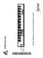
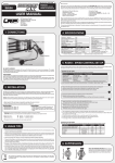
- 2V
- 2V
+5V
+5V
+ 2V
+ 2V
G D
+
ZEUS Access
Front Panel Interface for
ZEUS Studio Bus
V 1.0
ZEUS Access
+
The Zeus Access provides an easy way of linking an external power supply to
the Zeus Power System using just 2HP of space. Together with the Zeus Studio
Bus board and a few simple steps, you can now power up a modular system with
ease!
Residing on the left-most side of your case, the Zeus Access supplies a convienent
interface to easily power the Zeus Powered Bus Board system from the external
Cincon-TTA laptop-style universal power supply. The Zeus Access can be installed
in a Eurorack case with a maximum depth of 5.5 inches as the connecting leads
are 7.5 inches long. This balances usability while maintaining the audio-grade
power of the Zeus Power System.
The Zeus Access contains an On-Off toggle switch and 2.5mm DC Barrel Jack
(Center Pin +,) from which two terminal-fitted leads can connect to the +15V and
GND connections of the Zeus Studio Bus board. Both the switch and barrel jack
are rated for a maximum load of 5 Amps, perfect for powering up to 3 Studio Bus
Boards.
(Continued)
ZEUS Access
The Access is fully compatible with the Cincon-TTA Universal Power Supply, a
power supply that we custom made together with Cincon Taiwan for powering the
Zeus Studio Bus System. These supplies can be used with mains voltages from
100 to 220V without the use of a transformer, only the proper country outlet plug
adapter.
ZEUS Access
Installation:
Prior to starting, please view the wiring diagram on the next page to get
an understanding of the entire process.
Push down the lever on the Zeus Studio Bus using a small flat screw driver or
your finger and insert the Green lead to the “GND”, let go of the lever and the
wire will be locked.
Do the same as above, this time insert the Red lead to the “+15V”, let go of the
lever and the wire will be locked.
Make sure both leads are fully inserted into the terminal holes.
Attach the Zeus Studio Bus Board to the case as described in the Zeus Studio Bus
Board manual.
Attach the Zeus Access to the left-most side of your case.
Make sure that both of the leads from the Zeus Access are connected to their
correct spots. RED to +15V, GREEN to GND. Check the illustration below for
reference. NOTE: If the leads are incorrectly installed, you will damage the bus
board!
Connect the Cincon-TTA supply into mains voltage and with the Access’ toggle
switch in the OFF position, plug in the power supply’s barrel connector into the
Access’ DC jack.
While keeping your hand close to the switch, toggle the switch to the ON position
and observe that all three LED’s turned on after 1 second (+5V will turn on first,
+/-12V will turn on after about 1 second NOTE: If one or more LED’s do not light
up upon power up, QUICKLY toggle the switch to the OFF position and doublecheck that the wiring scheme outlined earlier is correct.
For more in-depth information on Zeus Studio Bus Board installation
techniques, recommended installation hardware,
guidelines, and dimensions, please refer to the
“Zeus Studio Bus Board” manual.
(Continued)
+
-
N
+15V
GND
0
Wiring Diagram for One Zeus Studio Bus Board
ZEUS Access
+5V
+12V
+5V
+12V
GND
12V
12V
+
-
+15V
GND
C
0
0
Wiring Diagram for Two Zeus Studio Bus Boards
ZEUS Access
+5V
+5V
+5V
+12V
+5V
+12V
GND
12V
12V
GND
12V
+12V
12V
+12V