1
Fast Arduino Oscilloscope Project User Manual
EARTH PEOPLE TECHNOLOGY, Inc
FAST ARDUINO OSCILLOSCOPE PROJECT
User Manual
The Fast Oscilloscope is designed for EPT USB CPLD Development System. It
converts an analog signal to digital and displays the result on the PC in real time.
Circuit designs, software and documentation are copyright © 2012-2014, Earth People
Technology, Inc
Page 1
Fast Arduino Oscilloscope Project User Manual
Microsoft and Windows are both registered trademarks of Microsoft Corporation.
Altera is a trademark of the Altera Corporation. All other trademarks referenced herein
are the property of their respective owners and no trademark rights to the same are
claimed.
Table of Contents
1
Fast Oscilloscope Introduction.................................................................................. 4
1.1 Driver Installation ............................................................................................... 4
1.2 Software Installation ........................................................................................... 5
1.3 Active Host EndTerms ....................................................................................... 5
1.4 Active Transfer Library EndTerms .................................................................... 6
2 The Development Process ......................................................................................... 7
2.1 Designing a Simple Fast Oscilloscope ............................................................... 8
2.2 Fast Oscilloscope Equipment Needed ................................................................ 8
2.3 Oscilloscope Hardware ....................................................................................... 9
2.4 Fast Oscilloscope Data Flow ............................................................................ 10
2.4.1
Arduino Functionality ............................................................................... 11
2.4.2
UnoProLogic Functionality....................................................................... 12
2.4.3
C# Window Functionality ......................................................................... 13
3 Arduino-Girino Fast Oscilloscope Code ................................................................. 14
3.1 Girino - Fast Arduino Oscilloscope.................................................................. 14
3.2 Disclaimer: THE AUTHOR OF THIS INSTRUCTABLE MAKES NO
GUARANTEE OF VALIDITY AND NO WARRANTY WHATSOEVER. ............ 15
3.3 What you need .................................................................................................. 16
3.4 Debug output .................................................................................................... 17
3.5 Setting register bits ........................................................................................... 18
3.6 What are the Interrupts ..................................................................................... 19
3.7 Continuously acquire with a circular buffer ..................................................... 19
3.8 Oscilloscope Triggering ................................................................................... 21
3.9 How the ADC works ........................................................................................ 22
3.10
Digital input buffers ...................................................................................... 23
3.11
Setting up the ADC ....................................................................................... 24
3.12
How the Analog Comparator works ............................................................. 27
3.13
Setting up the Analog Comparator ............................................................... 28
3.14
Threshold ...................................................................................................... 29
3.15
How the Pulse Width Modulation works ...................................................... 30
3.16
Setting up the PWM...................................................................................... 31
3.17
Volatile variables .......................................................................................... 33
3.18
Writing the kernel of the sketch .................................................................... 34
3.19
Building Arduino Project .............................................................................. 35
3.20
Programming the Arduino ............................................................................ 38
4 CPLD Active Transfer EndTerms Coding .............................................................. 40
Page 2
Fast Arduino Oscilloscope Project User Manual
4.1 Define the User Design. ................................................................................... 40
4.2 Select the Input/Outputs ................................................................................... 41
4.3 Registers and Parameters .................................................................................. 43
4.4 Assignments ..................................................................................................... 43
4.5 Reset Circuit ..................................................................................................... 43
4.6 Input Registers .................................................................................................. 44
4.7 Start/Stop and Write Enable detection ............................................................. 44
4.8 Transfer Control Register State Machine ......................................................... 45
4.9 USB Transfer State Machine ............................................................................ 46
4.10
EndTerm Instantiation .................................................................................. 47
4.11
Compile/Synthesize the Project .................................................................... 47
4.12
Synthesizing .................................................................................................. 51
4.13
Program the CPLD........................................................................................ 54
5 PC: C# Project Design ............................................................................................ 58
5.1 Coding the C# Project ...................................................................................... 59
C# Project Creation .......................................................................................... 60
5.1.1 ......................................................................................................................... 60
5.1.2
C# Project Environment Setup .................................................................. 62
5.1.3
C# Object Initialization ............................................................................. 67
5.1.4
C# Project ListDevices .............................................................................. 67
5.1.5
C# Project Open Device ............................................................................ 69
5.1.6
C# Project Callback Initialization ............................................................. 70
5.1.7
C# Project Controls ................................................................................... 71
5.1.8
C# Project Buttons .................................................................................... 72
5.1.9
C# Project EPTReadFunction Callback .................................................... 78
5.1.10 C# Project Completion .............................................................................. 79
5.2 PC: Compiling the Active Host Application .................................................... 79
5.2.1
Adding the DLL’s to the Project ............................................................... 80
6 Connecting the Project Together ............................................................................. 81
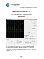
6.1 Testing the Project ............................................................................................ 85
6.1.1
Oscilloscope Description .......................................................................... 86
6.1.2
Oscilloscope Functions ............................................................................. 87
6.1.3
Oscilloscope Performance ......................................................................... 87
Page 3
Fast Arduino Oscilloscope Project User Manual
1 Fast Oscilloscope Introduction
The Fast Oscilloscope uses the Earth People Technology USB-CPLD development
system hardware and the Arduino Uno connected to a Windows PC. The project
software uses the Microsoft C# Express in conjunction with the Active Host dll.
This User Manual will guide the user to create the Arduino code that will sample the
Analog input and transfer the digitally converted samples to the CPLD. The user will be
given instructions on creating the CPLD code that accepts each sample from the
Arduino and transmits it via USB to the PC. The manual completes with instruction of
how to create the C# application that will decode each sample and display on the screen.
This is an advanced project and not for beginners to the Arduino family. However, it
does serve as an introduction to advanced programming techniques using Verilog for
programming the CPLD and C# for programming the user interface on the PC. The first
two sections provide a background for the PC and CPLD libraries.
1.1 Driver Installation
Follow the instructions in the EPT USB CPLD Development System User Manual to
install all of the software and drivers for use with the hardware.
Page 4
Fast Arduino Oscilloscope Project User Manual
If the driver has been installed correctly, you can go to the Device Manager and click on
the Universal Serial Bus controllers and see “USB Serial Converter A” and “USB Serial
Converter B”.
1.2 Software Installation
Follow the the instructions in the EPT USB CPLD Development System User Manual
to install the following software:
Altera Quartus II
Microsoft C# Express
Arduino Wiring IDE
1.3 Active Host EndTerms
The Active Host SDK is provided as a dll which easily interfaces to application
software written in C#, C++ or C. It runs on the PC and provides transparent connection
from PC application code through the USB driver to the user CPLD code. The user code
connects to “Endterms” in the Active Host dll. These Host “Endterms” have
Page 5
Fast Arduino Oscilloscope Project User Manual
complementary HDL “Endterms” in the Active Transfer Library. Users have seamless
bi-directional communications at their disposal in the form of:
Trigger Endterm
Transfer Endterm
Block Endterm
User code writes to the Endterms as function calls. Just include the address of the
individual module (there are eight individually addressable modules of each Endterm).
Immediately after writing to the selected Endterm, the value is received at the HDL
Endterm in the CPLD.
Receiving data from the CPLD is made simple by Active Host. Active Host transfers
data from the CPLD as soon as it is available. It stores the transferred data into circular
buffer. When the transfer is complete, Active Host invokes a callback function which is
registered in the users application. This callback function provides a mechanism to
transparently receive data from the CPLD. The user application does not need to
schedule a read from the USB or call any blocking threads.
1.4 Active Transfer Library EndTerms
The Active Transfer Library is a portfolio of HDL modules that provides an easy to use
yet powerful USB transfer mechanism. The user HDL code communicates with
EndTerms in the form of modules. These EndTerm modules are commensurate with the
Active Host EndTerms. There are three types of EndTerms in the Active Transfer
Library:
Trigger Endterm
Transfer Endterm
Block Endterm
They each have a simple interface that the user HDL code can use to send or receive
data across the USB. Writing to an EndTerm will cause the data to immediately arrive
Page 6
Fast Arduino Oscilloscope Project User Manual
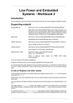
TRIGGER ENDTERM
ACTIVE TRANSFER
LIBRARY
SINGLE TRANSFER
ENDTERM
USER CODE
BLOCK ENDTERM
at the commensurate EndTerm in the Active Host/user application. The transfer through
the USB is transparent. User HDL code doesn’t need to set up Endpoints or respond to
Host initiated data requests. The whole process is easy yet powerful.
2 The Development Process
The development of the Fast Oscilloscope starts with the Arduino. The user will write
the code to sample an Analog input using the ADC in 8 bit mode, then assert the write
enable which initiates the read cycle on the EPT-570-AP board. The user will write the
Verilog code for the CPLD which stores each sample from the Arduino board, then
Page 7
Fast Arduino Oscilloscope Project User Manual
initiates the write cycle to PC. Finally, the user will write the C# code to accept each
byte from the EPT-570-AP board and assemble the bytes into the original analog signal
and display it in the graphics box in a Windows Form.
2.1 Designing a Simple Fast Oscilloscope
The Fast Oscilloscope is an advanced project and not for beginners to the Arduino
family. However, it does serve as an introduction to advanced programming techniques
using Verilog for programming the CPLD and C# for programming the user interface
on the PC. The user should be familiar with the beginners projects for the Arduino Uno.
For an introduction to Verilog, go to:
www.asic-world.com/verilog/intro1.html#Introduction
For an introduction to C#, go to:
http://www.homeandlearn.co.uk/csharp/csharp.html
2.2 Fast Oscilloscope Equipment Needed
The equipment you will need for the Fast Oscilloscope is
Page 8
Fast Arduino Oscilloscope Project User Manual
Arduino Uno
EPT UnoProLogic
USB Type A cable
USB Type Mini B cable
Solid core wire
+5VDC Variable Power Supply with cables
Function Generator with cables
2.3 Oscilloscope Hardware
The Arduino uses the analog comparator to trigger the scope. The ADC then samples
the analog channel 0. The samples are stored in a buffer in the ATMega328 SRAM.
Because of the method of using the Arduino hardware to behave as an oscilloscope, we
have to build some hardware. The analog signal must be applied to both the analog
channel 0 and the input to the analog comparator.
To do this, connect the UnoProLogic to the Uno.
Next, connect the +5V variable power supply up.
Connect the ground to pin 6 of J12 on the UnoProLogic.
Page 9
Fast Arduino Oscilloscope Project User Manual
Connect the positive lead of the supply to Digital input 7 (pin 8 of J8 on the
UnoProLogic).
Next, connect the ground lead of the of the Function Generator to pin 7 of J12.
Next, we need to build a cable that connects the signal to be displayed to Analog 0 (pin
1 of J9 on the UnoProLogic) and to Digital input 6 (pin 7 of J8 on the UnoProLogic).
Finally, connect the positive lead of the Function Generator to the Y cable that connects
analog input 0 and comparator input.
2.4 Fast Oscilloscope Data Flow
The Fast Arduino Oscilloscope is controlled by the C# application. After applying
power and opening the UnoProLogic, use the button events to send commands to the
Arduino to perform selected functions, such as starting the display, changing the
Trigger polarity, voltage reference, etc. Use the sliders to select new values for the
Horizontal Time Base, Time Scale, Vertical scale, etc.
The data flow for the Fast Oscilloscope consists of the Arduino/Girino code, the
UnoProLogic code, and the C# Window code
Page
10
Fast Arduino Oscilloscope Project User Manual
2.4.1 Arduino Functionality
When the Arduino powers up, it initializes the ports, variables, and registers. Once the
UnoProLogic has been started, the “On” button will send the “Start ADC” command to
the Arduion-Girino code. When the “Start ADC” command is received and decoded, the
Girino code calls the
startADC()
and the
start AnalogComparator()
functions. The first function turns on the ADC (initialized in the setup() routine), and
causes the ADC to convert whatever is on its analog input into a digital word. When
this conversion is complete, an interrupt function is called, “ISR(ADC_vect)”. When
this happens, the loop() function is stopped and the interrupt function executes. It
examines if the trigger bit has been set. If it is not, then the “update” is set to true and
the interrupt exits. When the interrupt is complete, the loop() function continues with
the next instruction. It will eventually check if the “update” bit has been set. If so, the
value of the ADC conversion is stored in the “ADCBuffer” and the buffer array index is
Page
11
Fast Arduino Oscilloscope Project User Manual
incremented. The ADC has been configured to continuously start a new conversion on
the completion of the previous conversion.
This process repeats until the Analog comparator has sensed the input to the analog
channel has breached the threshold level. This is the trigger threshold level and is set by
applying an analog voltage at pin 8 of the J8 connector. The pin 8 of the J8 connector is
attached to the internal analog comparator inside of the ATMega328 chip. It is
connected to the “-“ negative input of the comparator. The “+” positive input to the
comparator is connected to pin 7 of the J8 connector. The Fast Arduino Oscilloscope
cable harness connects pin 7 of J8 to pin 1 of J9, this is the attachment for the analog
signal to be displayed on the oscilloscope.
When the analog input signal on the positive input to the comparator is greater than the
input on the negative input to the comparator, an interrupt is called. This interrupt is
“ISR(ANALOG_COMP_vect)”. The loop() function will exit and start execution of the
first instruction in the comparator interrupt vector. The first thing is to turn off the
analog comparator interrupt so that no following comparator interrupts can disrupt the
process. Next, the “wait” variable is set to true. The “stopindex” is then set to the
current count of the “ADCCounter” plus an additional number of counts set by
“waitDuration”. These extra counts will allow a full cycle of the analog input signal to
be captured and displayed. Finally, the value “TriggerCount” is set to the ADCCounter.
This will be used when transmitting the ADCBuffer to the UnoProLogic.
When the ADCBuffer has completed transmission, the Girino code asserts the “End Of
Buffer” signal. This signal is used to create Trigger 2 in the Active Trigger Endterm.
After that, reset the trigger variables and re-start the ADC.
During each cycle of the loop() function, The serial port is checked to see if a new
command has arrived from the C# application. If a new command has arrived, the
Girino code will perform the selected command.
2.4.2 UnoProLogic Functionality
The CPLD does not need any initialization as the device is ready to operate soon after
the power is applied. The data flow in the UnoProLogic starts with a wait loop for the
Start_Stop_Control signal to be asserted from the Control Register. Once this happens,
the data flow will fall into the wait loop for the Write Enable. When the Write Enable
from the Girino asserts, it causes the block of code that writes bytes into the FIFO to
read the data byte on Ports B and C. Then clock the byte into the FIFO. This process
continues until the internal FIFO count reaches eight bytes. When this happens, fifo_full
flag sets.
When the fifo_full signal is asserted, the State Machine leaves the IDLE state and enters
the STORE_FIFO_COUNT state. In this state the fifo_out_count is updated with the
full count of the FIFO. The state machine will immediately enter the
Page
12
Fast Arduino Oscilloscope Project User Manual
START_SEND_BLOCK state and asserts the block_out_send signal which informs the
Active Block Endterm that a block transfer has started. This state will wait for the
block_busy signal to assert which is an acknowledgement that the block transfer has
been accepted by the Active Transfer Library.
Next, the FIFO_HI state is entered. In this state, Active Block Endterm toggles the
block_byte_ready signal to inform the user code to put a new byte on the
block_out_byte. The user code will toggle the FIFO read enable signal to push the first
byte in the FIFO onto the block_out_byte. The state machine will then cycle on to the
FIFO_LO state. In this state, the state machine will wait for the Active Transfer Library
to complete the transfer across the USB. When the transfer is complete, the
block_byte_ready signal goes low and causes the state machine to go to the
INCR_COUNT state. In this state, the block_out_flag is checked for assertion. If it is
asserted, the state machine goes to the FIFO_HI state to wait for block_byte_ready to
signal that the Active Block Endterm is ready for the next byte from the FIFO. If the
block_out_flag is not asserted in the INCR_COUNT state, then the block_out_counter
is checked to determine if the count has surpassed the fifo_out_count. If this statement
is true, state machine goes to the BLOCK_SEND_COMPLETE state. When the
block_busy signal de-asserts, the state machine goes back into the IDLE state. The data
flow waits in a loop for the fifo_full signal to assert again and start the process again.
2.4.3 C# Window Functionality
The C# data flow on the PC starts with the initialization of variables, controls, events,
and read callback functions. The Windows Form is displayed on the PC and the system
registry is scanned for any Earth People Technology devices. Any devices that are
found are added to the drop down box. The user must then select the available EPT
device and click the Open control. This will select the device and allocate all memory
needed for the Active Host EndTerms.
Next, the user must click on the Start button. Clicking this button will set the start/stop
bit of the control register and send it to the UnoProLogic. The CPLD will decode this
message and assert the Start_Stop_Control signal. Once this signal is asserted, the user
must click on the On/Off button to send a serial command to the Arduino. This is the
“Start ADC” command. This causes the Girino code to fill up the ADC Buffer. When
the Girino code has detected a trigger and filled the ADC Count has reached its max
“waitDuration”, it transmits all bytes in the ADC Buffer up to 500 bytes. Each byte is
transmitted through the Active Block Endterm of the CPLD code.
When the blocks are received by the C# Window, the read callback function is called.
The read callback will call the EPTParseReceive() function which calls the
TransferOutReceive() function. In this function, each byte is stored in the byte array:
“ScopeBuffer”. This process of filling the ScopeBuffer array continues until the Girino
code signals completion of the ADC Buffer transmission. When the Girino code has
Page
13
Fast Arduino Oscilloscope Project User Manual
completed the transmission of the entire ADC Buffer, it asserts the “End Of Buffer”
signal. This signal is connected to pin 3 of J9 of the UnoProLogic. The CPLD uses this
signal to send a Trigger 2 using the Active Trigger EndTerm. At this point the
ScopeBuffer has a complete cycle of the analog signal to display in its window. The
Trigger 2 Active Trigger Endterm causes the “invalidate()” function to be called. This
function will automatically cause the functions with a “Graphics” variable to be
refreshed. During the Refresh of the display data, the vertical and horizontal scaling is
performed. Nexti, Redrawing the graphics will cause the new values in the ScopeBuffer
to be displayed in the Oscilloscope window Finally, all data is displayed on screen. The
cycle repeats until the Stop button is pressed.
The button events will cause code to be executed when a button is pressed. The Visual
.NET framework takes care of the background code which monitors the button events
and any interrupts associated with executing this code.
3 Arduino-Girino Fast Oscilloscope Code
The following is a reprint from the Girino – Fast Arduino Oscilloscope by
Caffeinomane.
3.1 Girino - Fast Arduino Oscilloscope
I am a Physicist and the nicest part of working in this field is that I get to build my own
instruments. With this way of thinking, I decided to build a homebrew Arduino
Oscilloscope. This instructable was written with the purpose of teaching a bit about
microcontrollers and data acquisition.
Some time ago I was working on an Arduino project and I needed to see if the output
signal was into compliance with the specifics. Thus I spent some time on the
internet looking for Arduino Oscilloscopes already implemented, but I did not like what
I found. The projects that I found were mostly composed of a Graphical User
Interface for the computer written in Processing and a very simple arduino sketch. The
sketches were something like:
void setup() {
Serial.begin(9600);
}
void loop() {
int val = analogRead(ANALOG_IN);
Serial.println(val);
}
This approach is not wrong and I do not want to insult anyone, but this is too slow for
me. The serial port is slow and sending every result of an analogRead() through it is
a bottleneck.
Page
14
Fast Arduino Oscilloscope Project User Manual
I have been studying Waveform Digitizers for some time and I know reasonably well
how do they work, so I got inspiration from them. These were the starting points of
the oscilloscope that I wanted to create:
the incoming signal should be decoupled from the arduino to preserve it;
with an offset of the signal it is possible to see negative signals;
the data should be buffered;
a hardware trigger is required to catch the signals;
a circular buffer can give the signal shape prior to the trigger (more to follow on this
point);
using lower lever functions that the standard ones makes the program run faster.
The sketch for the Arduino is attached to this step, along with the schematic of the
circuit that I made.
The name that I came up with, Girino, is a frivolous pun in Italian. Giro means rotation
and adding the suffix -ino you get a small rotation, but Girino also means tadpole.
This way I got a name and a mascot.
3.2 Disclaimer: THE AUTHOR OF THIS INSTRUCTABLE MAKES
NO GUARANTEE OF VALIDITY AND NO WARRANTY
WHATSOEVER.
Electronics can be dangerous if you do not know what you are doing and the author
cannot guarantee the validity of the information found here. This is not a professional
advice and anything written in this instructable can be inaccurate, misleading,
dangerous or wrong. Do not rely upon any information found here without independent
verification.
It is up to you to verify any information and to double check that you are not exposing
yourself, or anyone, to any harm or exposing anything to any damage; I take no
Page
15
Fast Arduino Oscilloscope Project User Manual
responsibility. You have to follow by yourself the proper safety precautions, if you want
to reproduce this project.
Use this guide at your own risk!
3.3 What you need
What we really need for this project is an Arduino board and the datasheet of the
ATMega328P.
The datasheet is what tells us how the microcontroller works and it is very important to
keep it if we want a lower lever of control.
The datasheet can be found here: http://www.atmel.com/Images/doc8271.pdf
The hardware that I added to the Arduino is partly necessary, its purpose is just to form
the signal for the ADC and to provide a voltage level for the trigger. If you want,
you could send the signal directly to the Arduino and use some voltage reference
defined by a voltage divider, or even the 3.3 V given by the Arduino itself.
Page
16
Fast Arduino Oscilloscope Project User Manual
3.4 Debug output
I usually put a lot of debug output in my programs because I want to keep track of
anything that happens; the problem with Arduino is that we do not have a stdout to
write to. I decided to use the Serial port as a stdout.
Be aware, though, that this approach does not work all the times! Because writing to the
Serial port requires some time for the execution and it can dramatically change
things during some time sensible routines.
I usually define debugging outputs inside a preprocessor macro, so when the debug is
disabled they simply disappear from the program and do not slow down the
execution:
dprint(x); - Writes to the serial port something like: # x: 123
dshow("Some string"); - Writes the string
This is the definition:
#if DEBUG == 1
#define dprint(expression) Serial.print("# "); Serial.print( #expression ); Serial.print( ":
" ); Serial.println( expression )
#define dshow(expression) Serial.println( expression )
#else
#define dprint(expression)
Page
17
Fast Arduino Oscilloscope Project User Manual
#define dshow(expression)
#endif
3.5 Setting register bits
With the purpose of being fast, it is necessary to manipulate the microcontroller features
with lower lever functions than the standard ones provided by the Arduino IDE.
The internal functions are managed through some registers, that are collections of eight
bits where each one governs something particular. Each register contains eight
bits because the ATMega328P has an 8-bit architecture.
The registers have some names that are specified in the datasheet depending on their
meanings, like ADCSRA for the ADC Setting Register A. Also each meaningful bit
of the registers has a name, like ADEN for the ADC Enable Bit in the ADCSRA
register.
To set their bits we could use the usual C syntax for binary algebra, but I found on the
internet a couple of macros that are very nice and clean:
// Defines for setting and clearing register bits
#ifndef cbi
#define cbi(sfr, bit) (_SFR_BYTE(sfr) &= ~_BV(bit))
#endif
#ifndef sbi
#define sbi(sfr, bit) (_SFR_BYTE(sfr) |= _BV(bit))
#endif
Using them is very simple, if we want to set to 1 the Enable Bit of the ADC we can just
write:
sbi(ADCSRA,ADEN);
While if we want to set it to 0 (id est clear it) we can just write:
cbi(ADCSRA,ADEN);
Page
18
Fast Arduino Oscilloscope Project User Manual
3.6 What are the Interrupts
As we will see in the next steps, the use of interrupts is required in this project.
Interrupts are signals that tell the microcontroller to stop the execution of the main loop
and pass it to some special functions. The images give an idea of the program flow.
The functions that are executed are called Interrupt Service Routines (ISR) and are
more or less simple functions, but that do not take arguments.
Let us see an example, something like counting some pulses. The ATMega328P has an
Analog Comparator that has an interrupt associated that is activated when a
signal surpasses a reference voltage. First of all you must define the function that will
be exectuted:
ISR(ANALOG_COMP_vect)
{
counter++;
}
This is really simple, the instruction ISR() is a macro that tells the compiler that the
following function is an Interrupt Service Routine. While ANALOG_COMP_vect is
called Interrupt Vector and it tells the compiler which interrupt is associated to that
routine. In this case it is the Analog Comparator Interrupt. So everytime that the
comparator sees a signal bigger than a reference it tells the microcontroller to execute
that code, id est in this case to increment that variable.
The next step is to enable the interrupt associated. To enable it we must set the ACIE
(Analog Comparator Interrupt Enable) bit of the ACSR (Analog Comparator Setting
Register) register:
sbi(ACSR,ACIE);
In the following site we can see the list of all Interrupt Vectors:
http://www.nongnu.org/avr-libc/user-manual/group__avr__interrupts.html
3.7 Continuously acquire with a circular buffer
The concept of using a Circular Buffer is pretty straight forward:
Page
19
Fast Arduino Oscilloscope Project User Manual
Acquire continuously till a signal is found, then send the digitized signal to the
computer.
This approach allows to have the incoming signal shape also before the trigger event.
I prepared some diagrams to make myself clear. The following points are referring to
the images.
On the first image we can see what I mean with continuous acquisition. We define a
buffer that will store the data, in my case an array with 1280 slots, then we
start to continuously read the ADC output register (ADCH) ad filling the buffer with the
data. When we get to the end of the buffer we restart from the beggining
without clearing it. If we immagine the array arranged in a circular way it is easy to see
what I mean.
When the signal surpasses the threshold, the Analog Comparator Interrupt is activated.
Then we start a waiting phase in which we continue to acquire the signal
but keep a count of the ADC cycles that passed from the Analog Comparator Interrupt.
When we waited for N cycles (with N < 1280), we freeze the situation and stop the
ADC cycles. So we end up with a buffer filled with the digitization of the signal
temporal shape. The great part of this, is that we have also the shape prior to the trigger
event, because we were already acquiring before that.
Now we can send the whole buffer to the serial port in a block of binary data, instead of
sending the single ADC reads. This reduced the overhead required to
send the data and the bottleneck of the sketches that I found on the internet.
Page
20
Fast Arduino Oscilloscope Project User Manual
3.8 Oscilloscope Triggering
An oscilloscope shows on its display a signal, on that we all agree, but how can it show
it steadily and do not show it jumping around the screen? It has an internal trigger
that is able to show the signal always on the same position of the screen (or at least most
of the times), creating the illusion of a stable plot.
The trigger is associated with a threshold that activates a sweep when the signal passes
it. A sweep is the phase in which the oscilloscope records and displays the
signal. After a sweep another phase occurs: the holdoff, in which the oscilloscope
rejects any incoming signal. The holdoff period can be composed of a part of dead time,
in which the oscilloscope is unable to accept any signal, and a part that can be user
selectable. The dead time can be caused by various reasons like having to draw on
the screen or having to store the data somewhere.
Looking at the image we get a sense of what happens.
1. Signal 1 surpasses the threshold and activates the sweep;
2. signal 2 is inside the sweep time and gets caught with the first;
3. after the holdoff, signal 3 activates the sweep again;
4. instead signal 4 is rejected because it falls inside the holdoff region.
The raison d'être of the holdoff phase is to prevent some undesired signals to get in the
sweep region. It is a little bit long to explain this point and it eludes the purpose of
this instructable.
The moral of this story is that we need:
1. a threshold level to wich we can compare the incoming signal;
2. a signal that tells the microcontroller to start the waiting phase (see preceding step).
We have several possible solutions for point 1. :
using a trimmer we can manually set a voltage level;
using the PWM of the Arduino we can set the level by software;
using the 3.3 V provided by the Arduino itself;
using the internal bangap reference we can use a fixed level.
For point 2. we have the right solution: we can use the interrupt of the internal Analog
Comparator of the microcontroller.
Page
21
Fast Arduino Oscilloscope Project User Manual
3.9 How the ADC works
The Arduino microcontroller features a single 10-bit successive approximation ADC.
Before the ADC there is an analog multiplexer that lets us send, to the ADC, the
signals from different pins and sources (but only one at a time).
Successive Approximation ADC means that the ADC takes 13 clock cycles to complete
the conversion (and 25 clock cycles for the first conversion). There is a clock
signal dedicated to the ADC that is "computed" from the main clock of the Arduino;
this is because the ADC is a little slow and can not keep up with the pace of the other
parts of the microcontroller. It requires an input clock frequency between 50 kHz and
200 kHz to get maximum resolution. If a lower resolution than 10 bits is needed, the
input clock frequency to the ADC can be higher than 200 kHz to get a higher sample
rate.
But how much higher rates can we use? There are a couple of good guides about the
ADC at the Open Music Labs that I suggest to read:
http://www.openmusiclabs.com/learning/digital/atmega-adc/
http://www.openmusiclabs.com/learning/digital/atmega-adc/in-depth/
Since my purpose is to get a fast oscilloscope I decided to limit the precision to 8-bits.
This has several bonuses:
1. the data buffer can store more data;
2. you do not waste 6-bits of RAM per datum;
3. the ADC can acquire faster.
The prescaler lets us divide the frequency, by some factors, by setting the ADPS0-1-2
bits of the ADCSRA register. Seeing the plot of the precision from the Open Music
Labs Article, we can see that for 8-bits precision the frequency could go up to 1.5 MHz,
good! But since the ability of changing the prescaler factor lets us change the
acquisition rate, we can use it also to change the timescale of the oscilloscope.
There is a good feature about the output registers: we can decide the adjusting of
conversion bits, by setting the ADLAR bit in the ADMUX register. If it is 0 they are
right
Page
22
Fast Arduino Oscilloscope Project User Manual
adjusted and viceversa (see the image). Since I wanted 8-bits precision I set it to 1 so I
could read just the ADCH register and ignore the ADCL.
I decided to have just one input channel to avoid having to switch channel back and
forth at every conversion.
One last thing about the ADC, it has different running modes each one with a different
trigger source:
Free Running mode
Analog Comparator
External Interrupt Request 0
Timer/Counter0 Compare Match A
Timer/Counter0 Overflow
Timer/Counter1 Compare Match B
Timer/Counter1 Overflow
Timer/Counter1 Capture Event
I was interested in the free running mode that is a mode in which the ADC continuously
converts the input and throws an Interrupt at the end of each conversion
(associated vector: ADC_vect).
3.10 Digital input buffers
The analog input pins of the Arduino can also be used as digital I/O pins, therefore they
have an input buffer for digital functions. If we want to use them as analog pins
Page
23
Fast Arduino Oscilloscope Project User Manual
you should disable this feature.
Sending an analog signal to a digital pin induces it to toggle between HIGH and LOW
states, especially if the signal is near the boundary between the two states; this
toggling induces some noise to the near circuits like the ADC itself (and induces a
higher energy consumption).
To disable the digital buffer we should set the ADCnD bits of the DIDR0 register:
sbi(DIDR0,ADC5D);
sbi(DIDR0,ADC4D);
sbi(DIDR0,ADC3D);
sbi(DIDR0,ADC2D);
sbi(DIDR0,ADC1D);
sbi(DIDR0,ADC0D);
3.11 Setting up the ADC
In the sketch, I wrote a initialization function that sets-up all the parameters of the ADC
functioning. As I tend to write clean and commented code, I will just past the
function here. We can refer to the preceding step and to the comments for the meaning
of the registers.
void initADC(void)
{
//--------------------------------------------------------------------// ADMUX settings
//--------------------------------------------------------------------// These bits select the voltage reference for the ADC. If these bits
// are changed during a conversion, the change will not go in effect
// until this conversion is complete (ADIF in ADCSRA is set). The
// internal voltage reference options may not be used if an external
// reference voltage is being applied to the AREF pin.
// REFS1 REFS0 Voltage reference
// 0 0 AREF, Internal Vref turned off
// 0 1 AVCC with external capacitor at AREF pin
// 1 0 Reserved
// 1 1 Internal 1.1V Voltage Reference with external
Page
24
Fast Arduino Oscilloscope Project User Manual
// capacitor at AREF pin
cbi(ADMUX,REFS1);
sbi(ADMUX,REFS0);
// The ADLAR bit affects the presentation of the ADC conversion result
http://www.instructables.com/id/Girino-Fast-Arduino-Oscilloscope/
// in the ADC Data Register. Write one to ADLAR to left adjust the
// result. Otherwise, the result is right adjusted. Changing the ADLAR
// bit will affect the ADC Data Register immediately, regardless of any
// ongoing conversions.
sbi(ADMUX,ADLAR);
// The value of these bits selects which analog inputs are connected to
// the ADC. If these bits are changed during a conversion, the change
// will not go in effect until this conversion is complete (ADIF in
// ADCSRA is set).
ADMUX |= ( ADCPIN &0x07 );
//--------------------------------------------------------------------// ADCSRA settings
//--------------------------------------------------------------------// Writing this bit to one enables the ADC. By writing it to zero, the
// ADC is turned off. Turning the ADC off while a conversion is in
// progress, will terminate this conversion.
cbi(ADCSRA,ADEN);
// In Single Conversion mode, write this bit to one to start each
// conversion. In Free Running mode, write this bit to one to start the
// first conversion. The first conversion after ADSC has been written
// after the ADC has been enabled, or if ADSC is written at the same
// time as the ADC is enabled, will take 25 ADC clock cycles instead of
// the normal 13. This first conversion performs initialization of the
// ADC. ADSC will read as one as long as a conversion is in progress.
// When the conversion is complete, it returns to zero. Writing zero to
// this bit has no effect.
cbi(ADCSRA,ADSC);
// When this bit is written to one, Auto Triggering of the ADC is
// enabled. The ADC will start a conversion on a positive edge of the
// selected trigger signal. The trigger source is selected by setting
// the ADC Trigger Select bits, ADTS in ADCSRB.
sbi(ADCSRA,ADATE);
// When this bit is written to one and the I-bit in SREG is set, the
// ADC Conversion Complete Interrupt is activated.
sbi(ADCSRA,ADIE);
// These bits determine the division factor between the system clock
// frequency and the input clock to the ADC.
// ADPS2 ADPS1 ADPS0 Division Factor
Page
25
Fast Arduino Oscilloscope Project User Manual
// 0 0 0 2
// 0 0 1 2
// 0 1 0 4
// 0 1 1 8
// 1 0 0 16
// 1 0 1 32
// 1 1 0 64
// 1 1 1 128
sbi(ADCSRA,ADPS2);
sbi(ADCSRA,ADPS1);
sbi(ADCSRA,ADPS0);
//--------------------------------------------------------------------// ADCSRB settings
//--------------------------------------------------------------------// When this bit is written logic one and the ADC is switched off
// (ADEN in ADCSRA is zero), the ADC multiplexer selects the negative
// input to the Analog Comparator. When this bit is written logic zero,
// AIN1 is applied to the negative input of the Analog Comparator.
cbi(ADCSRB,ACME);
// If ADATE in ADCSRA is written to one, the value of these bits
// selects which source will trigger an ADC conversion. If ADATE is
// cleared, the ADTS2:0 settings will have no effect. A conversion will
// be triggered by the rising edge of the selected Interrupt Flag. Note
// that switching from a trigger source that is cleared to a trigger
// source that is set, will generate a positive edge on the trigger
// signal. If ADEN in ADCSRA is set, this will start a conversion.
// Switching to Free Running mode (ADTS[2:0]=0) will not cause a
// trigger event, even if the ADC Interrupt Flag is set.
// ADTS2 ADTS1 ADTS0 Trigger source
// 0 0 0 Free Running mode
// 0 0 1 Analog Comparator
// 0 1 0 External Interrupt Request 0
// 0 1 1 Timer/Counter0 Compare Match A
// 1 0 0 Timer/Counter0 Overflow
// 1 0 1 Timer/Counter1 Compare Match B
// 1 1 0 Timer/Counter1 Overflow
// 1 1 1 Timer/Counter1 Capture Event
cbi(ADCSRB,ADTS2);
cbi(ADCSRB,ADTS1);
cbi(ADCSRB,ADTS0);
//--------------------------------------------------------------------// DIDR0 settings
//--------------------------------------------------------------------Page
26
Fast Arduino Oscilloscope Project User Manual
http://www.instructables.com/id/Girino-Fast-Arduino-Oscilloscope/
// When this bit is written logic one, the digital input buffer on the
// corresponding ADC pin is disabled. The corresponding PIN Register
// bit will always read as zero when this bit is set. When an analog
// signal is applied to the ADC5..0 pin and the digital input from this
// pin is not needed, this bit should be written logic one to reduce
// power consumption in the digital input buffer.
// Note that ADC pins ADC7 and ADC6 do not have digital input buffers,
// and therefore do not require Digital Input Disable bits.
sbi(DIDR0,ADC5D);
sbi(DIDR0,ADC4D);
sbi(DIDR0,ADC3D);
sbi(DIDR0,ADC2D);
sbi(DIDR0,ADC1D);
sbi(DIDR0,ADC0D);
}
3.12 How the Analog Comparator works
The Analog Comparator is an internal module of the microcontroller and it compares
the input values on the positive pin (Digital Pin 6) and negative pin (Digital Pin 7).
When the voltage on the positive pin is higher than the voltage on the negative pin
AIN1, the Analog Comparator outputs a 1 in the ACO bit of the ACSR register.
Optionally, the comparator can trigger an interrupt, exclusive to the Analog
Comparator. The associated vector is ANALOG_COMP_vect.
We can also set the the interrupt to be launched on a rising edge, falling edge or on a
toggle of the state.
The Analog Comparator is just what we need for the triggering connecting out input
signal to pin 6, now what is left is a threshold level on pin 7.
Page
27
Fast Arduino Oscilloscope Project User Manual
3.13 Setting up the Analog Comparator
In the sketch, I wrote another initialization function that sets-up all the parameters of the
Analog Comparator functioning. The same issue about ADC digital buffers
applies to the Analog Comparator, as we can see on the bottom of the routine.
void initAnalogComparator(void)
{
//--------------------------------------------------------------------// ACSR settings
//--------------------------------------------------------------------// When this bit is written logic one, the power to the Analog
// Comparator is switched off. This bit can be set at any time to turn
// off the Analog Comparator. This will reduce power consumption in
// Active and Idle mode. When changing the ACD bit, the Analog
// Comparator Interrupt must be disabled by clearing the ACIE bit in
// ACSR. Otherwise an interrupt can occur when the bit is changed.
cbi(ACSR,ACD);
// When this bit is set, a fixed bandgap reference voltage replaces the
// positive input to the Analog Comparator. When this bit is cleared,
// AIN0 is applied to the positive input of the Analog Comparator. When
http://www.instructables.com/id/Girino-Fast-Arduino-Oscilloscope/
// the bandgap referance is used as input to the Analog Comparator, it
// will take a certain time for the voltage to stabilize. If not
// stabilized, the first conversion may give a wrong value.
cbi(ACSR,ACBG);
// When the ACIE bit is written logic one and the I-bit in the Status
// Register is set, the Analog Comparator interrupt is activated.
// When written logic zero, the interrupt is disabled.
cbi(ACSR,ACIE);
// When written logic one, this bit enables the input capture function
// in Timer/Counter1 to be triggered by the Analog Comparator. The
// comparator output is in this case directly connected to the input
// capture front-end logic, making the comparator utilize the noise
// canceler and edge select features of the Timer/Counter1 Input
// Capture interrupt. When written logic zero, no connection between
// the Analog Comparator and the input capture function exists. To
// make the comparator trigger the Timer/Counter1 Input Capture
// interrupt, the ICIE1 bit in the Timer Interrupt Mask Register
// (TIMSK1) must be set.
cbi(ACSR,ACIC);
// These bits determine which comparator events that trigger the Analog
// Comparator interrupt.
// ACIS1 ACIS0 Mode
Page
28
Fast Arduino Oscilloscope Project User Manual
// 0 0 Toggle
// 0 1 Reserved
// 1 0 Falling edge
// 1 1 Rising edge
sbi(ACSR,ACIS1);
sbi(ACSR,ACIS0);
//--------------------------------------------------------------------// DIDR1 settings
//--------------------------------------------------------------------// When this bit is written logic one, the digital input buffer on the
// AIN1/0 pin is disabled. The corresponding PIN Register bit will
// always read as zero when this bit is set. When an analog signal is
// applied to the AIN1/0 pin and the digital input from this pin is not
// needed, this bit should be written logic one to reduce power
// consumption in the digital input buffer.
sbi(DIDR1,AIN1D);
sbi(DIDR1,AIN0D);
}
3.14 Threshold
Recalling what we said about the trigger, we can implement these two solutions for the
threshold:
using a trimmer we can manually set a voltage level;
using the PWM of the Arduino we can set the level by software.
On the image we can see the hardware implementation of the threshold in both paths.
For the manual selection, a multi-turn potentiometer put between +5 V and GND is
sufficient.
While for software selection we need a low-pass filter that filters a PWM signal coming
from the Arduino. PWM signals (more on this to follow) are square signals with a
constant frequency but a variable pulse-width. This variability brings a variable mean
value of the signal that can be extracted with a low-pass filter. A good cutoff
frequency for the filter is about one hundredth of the PWM frequency and I chose about
560 Hz.
After the two threshold sources I inserted a couple of pins that allows to select, with a
jumper, which source I wanted. After the selection I also added an emitter follower
to decouple the sources from the Arduino pin.
Page
29
Fast Arduino Oscilloscope Project User Manual
3.15 How the Pulse Width Modulation works
As stated before, a Pulse Width Modulation (PWM) signal is a square signal with fixed
frequency but variable width. On the image we see an example. On each row there
is one of such signals with a different duty cycle (id est the period portion in which the
signal is High). Taking the mean signal over a period, we get the red line that
correspond to the duty cycle with respect to the signal maximum.
Electronically "taking the mean of a signal" can be translated to "passing it to a lowpass filter", as seen on the preceding step.
How does the Arduino generate a PWM signal? There is a really good tutorial about
PWM here:
http://arduino.cc/en/Tutorial/SecretsOfArduinoPWM
We will see just the points that are needed for this project.
In the ATMega328P there are three timers that can be used to generate PWM signals,
each one of those has different characteristics that you can use. For each timer
correspond two registers called Output Compare Registers A/B (OCRnx) that are used
to set the signal duty cycle.
As for the ADC there is a prescaler (see image), that slows down the main clock to have
a precise control of the PWM frequency. The slowed down clock is fed to a
counter that increments a Timer/Counter Register (TCNTn). This register is
continuously compared to the OCRnx, when they are equal a signal is sent to a
Waveform
Generator that generate a pulse on the output pin. So the trick is setting the OCRnx
register to some value to change the mean value of the signal.
If we want a 5 V signal (maximum) we must set a 100% duty cycle or a 255 in the
OCRnx (maximum for a 8-bit number), while if we want a 0.5 V signal we must set a
10% duty cycle or a 25 in the OCRnx.
Since the clock has to fill the TCNTn register before starting from the beginning for a
new pulse the output frequency of the PWM is:
f = (Main clock) / prescaler / (TCNTn maximum)
exempli gratia for the Timer 0 and 2 (8-bit) with no prescaler it will be: 16 MHz / 256 =
62.5 KHz while for Timer 1 (16-bit) it will be 16 MHz / 65536 = 244 Hz.
Page
30
Fast Arduino Oscilloscope Project User Manual
I decided to use the Timer number 2 because
Timer 0 is used internally by the Arduino IDE for functions such as millis();
Timer 1 has an output frequency too slow because it is a 16-bit timer.
In the ATMega328P there are different kinds of operation mode of the timers, but what
I wanted was the Fast PWM one with no prescaling to get the maximum possible
output frequency.
3.16 Setting up the PWM
In the sketch, I wrote another initialization function that sets-up all the parameters of the
Timer functioning and initializes a couple of pins.
void initPins(void)
{
//--------------------------------------------------------------------// TCCR2A settings
//--------------------------------------------------------------------// These bits control the Output Compare pin (OC2A) behavior. If one or
// both of the COM2A1:0 bits are set, the OC2A output overrides the
// normal port functionality of the I/O pin it is connected to.
// However, note that the Data Direction Register (DDR) bit
// corresponding to the OC2A pin must be set in order to enable the
// output driver.
// When OC2A is connected to the pin, the function of the COM2A1:0 bits
// depends on the WGM22:0 bit setting.
//
// Fast PWM Mode
// COM2A1 COM2A0
// 0 0 Normal port operation, OC2A disconnected.
// 0 1 WGM22 = 0: Normal Port Operation, OC0A Disconnected.
// WGM22 = 1: Toggle OC2A on Compare Match.
// 1 0 Clear OC2A on Compare Match, set OC2A at BOTTOM
// 1 1 Clear OC2A on Compare Match, clear OC2A at BOTTOM
Page
31
Fast Arduino Oscilloscope Project User Manual
cbi(TCCR2A,COM2A1);
cbi(TCCR2A,COM2A0);
sbi(TCCR2A,COM2B1);
cbi(TCCR2A,COM2B0);
// Combined with the WGM22 bit found in the TCCR2B Register, these bits
// control the counting sequence of the counter, the source for maximum
// (TOP) counter value, and what type of waveform generation to be used
// Modes of operation supported by the Timer/Counter unit are:
// - Normal mode (counter),
// - Clear Timer on Compare Match (CTC) mode,
// - two types of Pulse Width Modulation (PWM) modes.
//
// Mode WGM22 WGM21 WGM20 Operation TOP
// 0 0 0 0 Normal 0xFF
// 1 0 0 1 PWM 0xFF
// 2 0 1 0 CTC OCRA
// 3 0 1 1 Fast PWM 0xFF
// 4 1 0 0 Reserved // 5 1 0 1 PWM OCRA
// 6 1 1 0 Reserved // 7 1 1 1 Fast PWM OCRA
cbi(TCCR2B,WGM22);
sbi(TCCR2A,WGM21);
sbi(TCCR2A,WGM20);
//--------------------------------------------------------------------// TCCR2B settings
//--------------------------------------------------------------------// The FOC2A bit is only active when the WGM bits specify a non-PWM
// mode.
// However, for ensuring compatibility with future devices, this bit
// must be set to zero when TCCR2B is written when operating in PWM
// mode. When writing a logical one to the FOC2A bit, an immediate
// Compare Match is forced on the Waveform Generation unit. The OC2A
// output is changed according to its COM2A1:0 bits setting. Note that
// the FOC2A bit is implemented as a strobe. Therefore it is the value
// present in the COM2A1:0 bits that determines the effect of the
// forced compare.
// A FOC2A strobe will not generate any interrupt, nor will it clear
// the timer in CTC mode using OCR2A as TOP.
// The FOC2A bit is always read as zero.
cbi(TCCR2B,FOC2A);
cbi(TCCR2B,FOC2B);
// The three Clock Select bits select the clock source to be used by
Page
32
Fast Arduino Oscilloscope Project User Manual
// the Timer/Counter.
// CS22 CS21 CS20 Prescaler
// 0 0 0 No clock source (Timer/Counter stopped).
// 0 0 1 No prescaling
// 0 1 0 8
// 0 1 1 32
// 1 0 0 64
// 1 0 1 128
// 1 1 0 256
// 1 1 1 1024
cbi(TCCR2B,CS22);
cbi(TCCR2B,CS21);
http://www.instructables.com/id/Girino-Fast-Arduino-Oscilloscope/
sbi(TCCR2B,CS20);
pinMode( errorPin, OUTPUT );
pinMode( thresholdPin, OUTPUT );
analogWrite( thresholdPin, 127 );
}
3.17 Volatile variables
I can not remember where, but I read that variables that are modified inside an ISR
should be declared as volatile.
Volatile variables are variables that can change during time, even if the program that is
running does not modify them. Just like Arduino registers that can change value
for some external interventions.
Why does the compiler want to know about such variables? That is because the
compiler always tries to optimize the code that we write, to make it faster, and it
modifies
it a little bit, trying not to change its meaning. If a variable changes by its own it could
seem to the compiler that it is never modified during execution of, say, a loop and it
could ignore it; while it could be crucial that the variable changes its value. So declaring
volatile variables it prevents the compiler to modify the code concerning those.
For some more information I suggest to read the Wikipedia page:
http://en.wikipedia.org/wiki/Volatile_variable
Page
33
Fast Arduino Oscilloscope Project User Manual
3.18 Writing the kernel of the sketch
Finally we have gotten to the kernel of the program!
As we saw before, I wanted a continuous acquisition and I wrote the ADC Interrupt
Service Routine to store in the circular buffer the data continuously. It stops whenever
it reaches the index that is equal to stopIndex. The buffer is implemented as circular
employing the modulo operator.
//----------------------------------------------------------------------------// ADC Conversion Complete Interrupt
//----------------------------------------------------------------------------ISR(ADC_vect)
{
// When ADCL is read, the ADC Data Register is not updated until ADCH
// is read. Consequently, if the result is left adjusted and no more
// than 8-bit precision is required, it is sufficient to read ADCH.
// Otherwise, ADCL must be read first, then ADCH.
ADCBuffer[ADCCounter] = ADCH;
ADCCounter = ( ADCCounter + 1 ) % ADCBUFFERSIZE;
if ( wait )
{
if ( stopIndex == ADCCounter )
{
// Freeze situation
// Disable ADC and stop Free Running Conversion Mode
cbi( ADCSRA, ADEN );
freeze = true;
}
}
}
The Analog Comparator Interrupt Service Routine (that is called when a signal passes
the threshold) disables itself and tells the ADC ISR to start the waiting phase and
sets the stopIndex.
http://www.instructables.com/id/Girino-Fast-Arduino-Oscilloscope/
//----------------------------------------------------------------------------// Analog Comparator interrupt
Page
34
Fast Arduino Oscilloscope Project User Manual
//----------------------------------------------------------------------------ISR(ANALOG_COMP_vect)
{
// Disable Analog Comparator interrupt
cbi( ACSR,ACIE );
// Turn on errorPin
//digitalWrite( errorPin, HIGH );
sbi( PORTB, PORTB5 );
wait = true;
stopIndex = ( ADCCounter + waitDuration ) % ADCBUFFERSIZE;
}
This was really easy after all that grounding!
3.19 Building Arduino Project
Building the Arduino project is the process of converting (compiling) the code you just
wrote into machine level code that the processor can understand. The Arduino IDE is
the software tool that does the compiling. The machine level code is a set of basic
instructions that the processor uses to perform the functions the user code. Browse to
the \Projects_Arduino\Arduino_Fast Oscilloscope\ Arduino_Fast
Oscilloscope_Code_U2\ folder of the UNO_FAST OSCILLOSCOPE_PROJECT_CD.
Locate the Arduino_ Fast Oscilloscope_Code_U2.ino file.
To compile your code,
Open up the Arduino IDE
Page
35
Fast Arduino Oscilloscope Project User Manual
Load your code into the Sketch.
Page
36
Fast Arduino Oscilloscope Project User Manual
Click the Verify button
Page
37
Fast Arduino Oscilloscope Project User Manual
The sketch will compile
If there are no errors, the compiling will complete successfully
Now we are done with compiling and ready to program the Arduino
3.20 Programming the Arduino
Programming the Arduino is the process of downloading the user’s compiled code into
the Flash memory of the Atmel ATMega328 chip. Once the code is downloaded, the
Arduino IDE resets the chip and the processor starts executing out of Flash memory.
To program the Arduino
Connect the USB cable from PC to Arduino
Page
38
Fast Arduino Oscilloscope Project User Manual
Plug in your board and wait for Windows complete the driver installation
process.
Next, click on Tools and select Serial Port, then click the available port.
To load the code, click on the Upload button.
Page
39
Fast Arduino Oscilloscope Project User Manual
When the code has completed loading, the Arduino IDE will automatically command
the processor to start executing the code. The Arduino is now ready for the EPT-570AP.
4 CPLD Active Transfer EndTerms Coding
The EPT-570-AP will accept the digitized data sampled by the Arduino and transfer it
to the PC. It is designed to plug directly into the Arduino Uno and there is no need for
external wires to be added. The Active Transfer Library is used to send the data to the
PC. The Active Transfer EndTerms are used to connect the Active Transfer Library to
the user code. This makes it easy to transfer data to and from the PC via the USB. The
user needs to create a state machine to control the transfer between the incoming data
and the Active Transfer EndTerms.
4.1 Define the User Design.
In this step we will define the user’s code and include EndTerms and the EPT Active
Transfer Library. The Active Transfer Library contains a set of files with a “.vqm”
name extension which select particular operations to perform (e.g., byte transfer, block
transfer, trigger).. The active_transfer_library.vqm file must be included in the top level
file of the project. The EndTerms will connect to the active_transfer_library and
provide a path to connect user code to the library. All of these files are available on the
Earth People Technology Project CD.
Page
40
Fast Arduino Oscilloscope Project User Manual
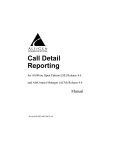
TRIGGER ENDTERM
ACTIVE TRANSFER
LIBRARY
SINGLE TRANSFER
ENDTERM
USER CODE
BLOCK ENDTERM
We will build our CPLD project using Quartus II software from Altera. The primary file
defining the user’s CPLD project is named “EPT_570_AP_U2_Top.v”. It defines the
user code and connects the active_transfer_library and Endterms.
www.asic-world.com/verilog/intro1.html#Introduction
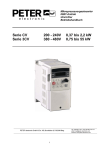
4.2 Select the Input/Outputs
We need to set the inputs and outputs for EPT_570_AP_U2_Top.v. The I/O nets will
stay the same for all EPT projects. All of the usable pins are connected to traces on the
EPT-570-AP board and serve specific functions. However, the pins that connect to the
Arduino can be set to either inputs or outputs. It is in the port section of the Verilog
module that the Arduino pins can be set. For the Fast Oscilloscope, we will read from
the J8 and J10 connectors. So, we set these as inputs. Since the analog inputs to the
Arduino are on the J9 connector, we will set it up as inputs. The following nets are used
to connect to the EPT-570-AP connectors.
Page
41
Fast Arduino Oscilloscope Project User Manual
Signal
ADC
Bits 1 to 0
Arduino Uno
Port
Pin
C
5 to 4
Connector
IOL
Connector
J8
EPT-570-AP
Pin
Port
6 to 4 LB_IOL
Write Enable
ADC Bit 7
B
5
IOH
J10
4
LB_IOH
ADC Bit 6
B
4
IOH
J10
1
LB_SER
ADC Bit 5
B
3
IOH
J10
3
LB_IOH
ADC Bit 4
B
2
IOH
J10
2
LB_IOH
ADC Bit 3
B
1
IOH
J10
1
LB_IOH
ADC Bit 2
B
0
IOH
J10
0
LB_IOH
Connects
To
Each net is followed by the net type wire or reg. If it is a vector, the array description
must be added.
Page
42
Signal
Fast
Oscilloscope_
lower_byte
Fast
Oscilloscope_
upper_byte(1)
Fast
Oscilloscope_
upper_byte(0)
Fast
Oscilloscope_
address(2)
Fast
Oscilloscope_
address(1)
Fast
Oscilloscope_
address(0)
Fast
Oscilloscope_
en
Fast Arduino Oscilloscope Project User Manual
4.3 Registers and Parameters
4.4 Assignments
Next, add the assignments. These assignments will set the direction of the bus
transceivers that interface to the Arduino I/O’s. The transceivers also include an output
enable bit.
4.5 Reset Circuit
The reset signal is generated by a counter that starts counting upon power up. When the
counter reaches GLOBAL_RESET_COUNT.
Page
43
Fast Arduino Oscilloscope Project User Manual
4.6 Input Registers
The section labled “Register the Inputs” applies the inputs from the Arduino to clocked
registers. This will eliminate any noise on these inputs from propagating through to the
state machines of the CPLD.
4.7 Start/Stop and Write Enable detection
Next, we will add the transfer detection signal from the Arduino. This block will sample
the Write Enable signal and wait for it to go high.
It is also used to provide start/stop control for the CPLD code. This block will use four
registers to control the data and starting the state machine.
Page
44
Fast Arduino Oscilloscope Project User Manual
transfer_write_reg –This is a latch register to hold the state of the Write Enable.
transfer_write –This register is used to start the state machine and initiate the
multi byte write to the PC.
transfer_write_data –This is a 10 bit register to hold the value of the analog
sample from the Arduino.
transfer_address – 8 bit register to hold the EndTerm address from the Arduino.
The start_stop_cntrl signal is monitored every clock cycle. If it is sampled high, the
output enables of the 74LVC4245 transceivers are set low and the outputs become
active. When start_stop_cntrl goes low, the output enables of the 74LVC4245
transceivers are set high and sets the outputs to inactive.
4.8 Transfer Control Register State Machine
The start_stop_cntrl signal is set by using the TRANSFER_CONTROL state machine
in the following section. So, if the start_stop_cntrl signal is set, the CPLD code will
enter the conditional branch code and wait for the Write Enable signal to assert.
Next, we add the TRANSFER_CONTROL state machine to read the Control Register
from the Host PC using the active_transfer EndTerm. This state machine will decode
the 8 bit control register only after a sequence of three 8 bit bytes in the order of 0x5a,
0xc3, 0x7e. The operation of the state machine is as follows.
1. The TRANSFER_CONTROL state machine will stay in the idle state of the
parallel encoder until a byte from the active_transfer transfer_to_device register
receives a 0x5a.
2. This will cause the transfer_control_state to be changed to
TRANSFER_CONTROL_HDR1.
3. The state machine will stay in the TRANSFER_CONTROL_HDR1 state until
the next byte is read from the active_transfer.
4. If the byte from transfer_to_device is a 0xc3, the transfer_control_state will be
changed to TRANSFER_CONTROL_HDR2.
5. If the byte from transfer_to_device is not a 0xc3, the transfer_control_state will
go back to idle.
6. In the TRANSFER_CONTROL_HDR2 state , the state machine will stay in this
state until the next byte from the active_transfer is received.
7. If the byte from transfer_to_device is a 0x7e, the transfer_control_state will be
changed to TRANSFER_DECODE_BYTE.
8. If the byte from transfer_to_device is not a 0x7e, the transfer_control_state will
go back to idle.
9. In the TRANSFER_DECODE_BYTE state , the state machine will stay in this
state until the next byte from the active_transfer.
10. The next byte transferred from active_transfer will be decoded as the Control
Register.
Page
45
Fast Arduino Oscilloscope Project User Manual
The bits of the Control Register are defined below.
Register
Bits
Description
Control
0
Start Stop Cntrl
1
Not Used
2
LED Reset
3
Switch Reset
4
Transfer In Loop Back
5
Not Used
6
Not Used
7
Not Used
7
Not Used
Assertion
High
High
High
High
4.9 USB Transfer State Machine
The USB Transfer State Machine is quite a bit different than the Transfer Control state
machine. It is two always statement one-hot finite state machine. It is used here because
it provides high speed glitch free operation. One hot means that it has one register for
each state. The two always block setup allows a synchronous operation to be relegated
to moving the state machine to the next state.
An asynchronous always block is used to select which state will be the next state. All of
the outputs are handled in their own always blocks and separate from the state machine.
This asynchronous always block is the one which causes the state machines conditional
branches to update. If the conditional branches are not updated with the correct inputs,
Page
46
Fast Arduino Oscilloscope Project User Manual
then the next[…] statement will not get updated with the correct state and the state
machine could get stuck in the wrong state. So, each input into the state machine MUST
be entered into the sensitivity list of the “State Defiinitions” always block.
1.
2.
3.
4.
5.
6.
7.
The state machine stays in state[IDLE]
In state[STORE_FIFO_COUNT],
In state [START_SEND_BLOCK].
In state [FIFO_HI]
In state[FIFO_LO]
In state[INCR_COUNT]
In state[BLOCK_SEND_COMPLETE]
4.10 EndTerm Instantiation
4.11 Compile/Synthesize the Project
The Quartus II application will compile/ synthesize the user code,
active_transfer_library, and the Active EndTerms. The result of this step is a file
containing the CPLD code with “*.pof”. First, we need to create a project in the
Quartus II environment. Follow the directions in the section: “Compiling, Synthesizing,
and Programming CPLD” of the User Manual.
Bring up Quartus II, then use Windows Explorer to browse to
c:/altera/xxx/quartus/qdesigns create a new directory called: “EPT_Fast Oscilloscope”.
Page
47
Fast Arduino Oscilloscope Project User Manual
Open Quartus II by clicking on the icon .
Under Quartus, Select File->New Project Wizard. The Wizard will walk you through
setting up files and directories for your project.
Page
48
Fast Arduino Oscilloscope Project User Manual
Page
49
Fast Arduino Oscilloscope Project User Manual
At the Top-Level Entity page, browse to the c:\altera\xxx\quartus\qdesigns\EPT_Fast
Oscilloscope directory to store your project. Type in a name for your project
“EPT_570_AP_U2_Top”.
Follow the steps up to Add Files. At the Add Files box, click on the Browse button and
navigate to the project Fast Oscilloscope install folder in the dialog box. Browse to the
\Projects_HDL\EPT_ Fast Oscilloscope \EPT_570_AP_U2_Top folder of the EPT
USB-CPLD Development System CD. Copy the files from the \src directory.
Active_transfer.vqm
Active_trigger.vqm
Active_transfer_library.vqm
eptWireOr.v
ETP_570_AP_U2_Top.v
Add the files:
Select Next, at the Device Family group, select MAX II for Family. In the Available
Devices group, browse down to EPM570T100C5 for Name.
Page
50
Fast Arduino Oscilloscope Project User Manual
Select Next, leave defaults for the EDA Tool Settings.
Select Next, then select Finish. You are done with the project level selections.
4.12 Synthesizing
With the project created, we need to assign pins to the project. The signals defined in
the top level file (in this case: EPT_570_AP_U2_Top.v) will connect directly to pins on
the CPLD. The Pin Planner Tool from Quartus II will add the pins and check to verify
that our pin selections do not violate any restrictions of the device. In the case of this
example we will import pin assignments that created at an earlier time. Under
Assignments, Select Import Assignments.
At the Import Assignment dialog box, Browse to the
\Projects_HDL\EPT_Transfer_Test \Altera_EPM570_U2 folder of the EPT FAST
OSCILLOSCOPE_PROJECT CD. Select the “EPT_570_AP_U2_Top.qsf” file.
Page
51
Fast Arduino Oscilloscope Project User Manual
Next, we need to add the Synopsys Design Constraint file. This file contains timing
constraints which forces the built in tool called TimeQuest Timing Analyzer to analyze
the path of the synthesized HDL code with setup and hold times of the internal registers.
It takes note of any path that may be too long to appropriately meet the timing
qualifications. For more information on TimeQuest Timing Analyzer, see
http://www.altera.com/literature/hb/qts/qts_qii53018.pdf?GSA_pos=1&WT.oss_r=1&
WT.oss=TimeQuest Timing Analyzer
Browse to the \Projects_HDL\EPT_ Fast Oscilloscope \Altera_EPM570_U2 folder of
the EPT USB-CPLD Development System CD. Select the
“EPT_570_AP_U2_Top.sdc” file.
Copy the file and browse to c:\altera\xxx\quartus\qdesigns\EPT_Fast Oscilloscope
directory. Paste the file.
Page
52
Fast Arduino Oscilloscope Project User Manual
and select the Start Compilation button.
This will cause the compile and synthesization process. After successful completion, the
screen should look like the following:
Page
53
Fast Arduino Oscilloscope Project User Manual
If the synthesis fails, you will see the failure message in the message window. Note that
in addition to fatal errors, the compile process can produce “warnings” which do not
necessarily prevent execution of the code but which should be corrected eventually.
At this point the project has been successfully compiled, synthesized and a
programming file has been produced. See the next section on how to program the
CPLD.
4.13 Program the CPLD
The final step is programming the “*.pof” file into the CPLD.
Connect the EPT-570-AP to the PC,
Open up Quartus II,
Open the programmer tool
If the project created in the previous sections is not open, open it. Click on the
Programmer button.
Page
54
Fast Arduino Oscilloscope Project User Manual
The Programmer Window will open up with the programming file selected. Click on the
Hardware Setup button in the upper left corner.
The Hardware Setup Window will open. In the “Available hardware items”, double
click on “EPT-Blaster v1.3b”.
Page
55
Fast Arduino Oscilloscope Project User Manual
If you successfully double clicked, the “Currently selected hardware:” dropdown box
will show the “EPT-Blaster v1.3b”.
Click the “Close” button.
Next, selet the checkbox under the “Program/Configure” of the Programmer Tool. The
checkboxes for the CFM and UFM will be selected automatically.
Page
56
Fast Arduino Oscilloscope Project User Manual
Click on the Start button to to start programming the CPLD. The Progress bar will
indicate the progress of programming.
When the programming is complete, the Progress bar will indicate success.
Page
57
Fast Arduino Oscilloscope Project User Manual
At this point, the EPT-570-AP is programmed and ready for use.
5 PC: C# Project Design
The final piece of the Fast Oscilloscope is the PC application. This application will
fetch the data from the CPLD of the EPT-570-AP and display it on the screen. It
includes user code, windows form, and the Active_Host DLL.
The Active_Host DLL is designed to transfer data from the CPLD when it becomes
available. The data will be stored into local memory of the PC, and an event will be
triggered to inform the user code that data is available from the addressed module of the
CPLD. This method, from the user code on the PC, makes the data transfer transparent.
The data just appears in memory and the user code will direct the data to a textbox on
the Windows Form.
The Fast Oscilloscope will perform the following functions.
Find UnoProLogic Device.
Open UnoProLogic Device.
Start the Arduino data conversion process.
Wait for data from UnoProLogic.
Add byte to ScopeBuffer.
Wait for Trigger 2 to signal End of Buffer
Display digital data on a graphics window.
Page
58
Fast Arduino Oscilloscope Project User Manual
5.1 Coding the C# Project
The user code is based on the .NET Framework and written in C#. The language is great
for beginners as it is a subset of the C++ language. It has the look and feel of the
familiar C language but adds the ease of use of classes, inheritance and method
overloading. C# is an event based language which changes the method of writing code
for this project. You will need to get some background knowledge in coding with C#
and the .NET Framework on the PC. For a better description of event based language
programming and C#, see the following for a turtorial
http://www.homeandlearn.co.uk/csharp/csharp.html
Page
59
Fast Arduino Oscilloscope Project User Manual
5.1.1 C# Project Creation
To start the project, use the wizard to create project called “EPT_Fast Oscilloscope”.
When the wizard completes, the C# Express main window will look like the following.
The setup statements create the namespace and the class for the project. There are
several other files that are created by the wizard such as Form1.Designer.cs,
Program.cs, Form1.resx. We don’t need to go into these support files, we will just focus
on the Form1.cs as this is where all the user code goes.
Click on File->Save Project as. Browse to C:\Users\<user name>\Documents\Visual
Studio 2010\Projects, and click Select Folder. Click the Save button.
Page
60
Fast Arduino Oscilloscope Project User Manual
Locate the \Projects_ActiveHost_64Bit\EPT_Fast Oscilloscope\ folder in the
UNO_FAST OSCILLOSCOPE_PROJECT_CD. Copy the following files:
active_transfer_x64.cs
Form1.cs
Form1.Designer.cs
Form1.resx
Program.cs
ScaleFactorMenu.cs
Open a Windows Explorer window and browse to
C:\Users\NelsonsTrfgr\Documents\Visual Studio 2010 \Projects \EPT_Fast
Oscilloscope \EPT_Fast Oscilloscope. Paste the files to this folder.
In the Solution Explorer Window, right click on the project name, EPT_Fast
Oscilloscope and select Add->Existing Item
Select the following files:
active_transfer_x64.cs
ScaleFactorMenu.cs
Page
61
Fast Arduino Oscilloscope Project User Manual
Click Add.
5.1.2 C# Project Environment Setup
The project environment must be set up correctly in order to produce an application that
runs correctly on the target platform. Visual C# Express defaults new projects to 32 bits.
If your OS is a 64 bit platform, use the following directions to set up a 64 bit project.
First, we need tell C# Express to produce 64 bit code if we are running on a x64
platform. Go to Tools->Settings and select Expert Settings
Go to Tools->Options, locate the “Show all settings” check box. Check the box.
Page
62
Fast Arduino Oscilloscope Project User Manual
In the window on the left, go to “Projects and Solutions”. Locate the “Show advanced
build configurations” check box. Check the box.
Go to Build->Configuration Manager.
Page
63
Fast Arduino Oscilloscope Project User Manual
In the Configuration Manager window, locate the “Active solution platform:” label,
select “New” from the drop down box.
In the New Solution Platform window, click on the drop down box under “Type or
select the new platform:” and select “x64”.
Page
64
Fast Arduino Oscilloscope Project User Manual
Click the Ok button. Verify that the “Active Solution Platform” and the “Platform” tab
are both showing “x64”.
Click Close.
Then, using the Solution Explorer, you can right click on the project, select Properties
and click on the Build tab on the right of the properties window.
Page
65
Fast Arduino Oscilloscope Project User Manual
Verify that the “Platform:” label has “Active (x64)” selected from the drop down box.
Next, unsafe code needs to be allowed so that C# can be passed pointer values from the
Active Host.
Locate the “Allow unsafe code” check box. Check the box
Page
66
Fast Arduino Oscilloscope Project User Manual
5.1.3 C# Object Initialization
Now we are ready to start coding.
Next, we add two classes for our device. One class stores the information useful for our
device for Transmit to the EndTerms such as, address of module, length of transfer etc.
The next class is used to store parameters for receiving data from the device.
The first function called when the Windows Form loads up is the EPT_Fast
Oscilloscope _Load(). This function is called automatically upon the completion of the
Windows Form, so there is no need to do anything to call it. Once this function is
called, it in turn calls the ListDevices().
5.1.4 C# Project ListDevices
The ListDevices() function calls the EPT_AH_Open() function to load up the
Page
67
Fast Arduino Oscilloscope Project User Manual
ActiveHost Dll. Next, it calls EPT_AH_QueryDevices() which searches through the
registry files to determine the number of EPT devices attached to the PC. Next,
EPT_AH_GetDeviceName() is called inside a for loop to return the ASCII name of
each device attached to the PC. It will automatically populate the combo box,
cmbDevList with all the EPT devices it finds.
Page
68
Fast Arduino Oscilloscope Project User Manual
5.1.5 C# Project Open Device
The user will select the device from the drop down combo box. This value can be sent
to the OpenDevice() function using the button Click of the Open button.
The device_index variable is used to store the index of the device selected from the
combo box. This variable is passed into the EPT_AH_OpenDeviceByIndex(). This
process is started by the user clicking on the “Open” button. If the function is
successful, the device name is displayed in the label, labelDeviceCnt. Next, the device
is made the active device and the call back function is registered using the
RegisterCallBack() function. Finally, the Open button is grayed out and the Close
button is made active.
Page
69
Fast Arduino Oscilloscope Project User Manual
5.1.6 C# Project Callback Initialization
Next, the callback function is populated. This function will be called from the Active
Host dll. When the EPT Device has transferred data to the PC, the callback function
will do something with the data and command.
Page
70
Fast Arduino Oscilloscope Project User Manual
Because the callback function communicates directly with the dll and must pass
pointers from the dll to the C#, marshaling must be used. Marshaling is an advanced C#
topic and will not be covered in this manual. We will let the callback function work in
the background and we only need to use the EPTParseReceive() function to handle
incoming data.
5.1.7 C# Project Controls
Controls such as buttons are added to the Form1.cs[Design] window which allow
turning on and off signals. These include
btnOk
btnCancel
btnOpenDevice
btnCloseDevice
btnStart
btnStop
btnSetScaleFactor
btnResetBlock1 .. 6
Textboxes are used to display information on the Windows form. These textboxes are:
Page
71
Fast Arduino Oscilloscope Project User Manual
cmbDevList
tbMonitor1
tbMonitor2
tbMonitor3
tbMonitor4
tbMonitor5
tbMonitor6
5.1.8 C# Project Buttons
Although, the C# language is very similar to C Code, there are a few major differences.
The first is C# .NET environment is event based. A second is C# utilizes classes. This
guide will keep the details of these items hidden to keep things simple. However, a brief
introduction to events and classes will allow the beginner to create effective programs.
Event based programming means the software responds to events created by the user, a
timer event, external events such as serial communication into PC, internal events such
as the OS, or other events. The events we are concerned with for our example program
are button clicks or dropdown box clicks. The user events occur when the user clicks on
a button on the Windows Form or selects a radio button. We will add a button to our
example program to show how the button adds an event to the Windows Form and a
function that gets executed when the event occurs.
The easiest way to add a button to a form is to double click the Form1.cs in the Solution
Explorer. Click on the
button to launch the Toolbox.
Page
72
Fast Arduino Oscilloscope Project User Manual
Locate the button on the Toolbox, grab and drag the button onto the Form1.cs [Design]
and drop it near the top.
Page
73
Fast Arduino Oscilloscope Project User Manual
Go to the Properties box and locate the (Name) cell. Change the name to
“btnOpenDevice”. Locate the Text cell, and change the name to Open.
Page
74
Fast Arduino Oscilloscope Project User Manual
Double click on the Open button. The C# Explorer will automatically switch to the
Form1.cs code view. The callback function will be inserted with the name of the button
along with “_click” appended to it. The parameter list includes (object sender,
System.EventArgs e). These two additions are required for the callback function to
initiate when the “click” event occurs.
Private void btnOpenDevice_click(object sender, System.EventArgs e)
There is one more addition to the project files. Double click on the Form1.Designer.cs
file in the Solution Explorer. Locate the following section of code.
This code sets up the button, size, placement, and text. It also declares the
“System.EventHandler()”. This statement sets the click method (which is a member of
Page
75
Fast Arduino Oscilloscope Project User Manual
the button class) of the btnOpenDevice button to call the EventHandler –
btnOpenDevice_Click. This is where the magic of the button click event happens.
When btnOpenDevice_Click is called, it calls the function “OpenDevice()”. This
function is defined in the dll and will connect to the device selected in the combo box.
This is a quick view of how to create, add files, and add controls to a C# project. The
user is encouraged to spend some time reviewing the online tutorial at
http://www.homeandlearn.co.uk/csharp/csharp.html to become intimately familiar with
Visual C# .NET programming. In the meantime, follow the examples from the Earth
People Technology to perform some simple reads and writes to the EPT USB-CPLD
Development System.
The btnOk and btnClose buttons are used to end the application. It calls the function
EPT_AH_CloseDeviceByIndex() to remove the device from the Active Host dll. The
buttons btnOpen and btnClose have their Enabled parameter set to true and false
respectively. The Enabled parameter controls whether the button is allowed to launch an
event or not. If it is not enabled, the button is grayed out. At the end of each click event,
the Application.Exit() method is called. This exits the form.
Page
76
Fast Arduino Oscilloscope Project User Manual
The btnStart and btnStop buttons are used to start and stop the EPT-570-AP USB
Trasnfer. They call the function EPT_AH_SendTransferControlByte() to set the bit 0 in
the control register. The function passes the control byte to the Active Host dll. They
both operate on the click event, which are setup in the Form1.Designer.cs file
The EPT_AH_SendTransferControlByte() requires two parameters, address and control
register. The address must correspond to the correct EndTerm in the EPT-570-AP code.
The button SetScaleFactor will call the ScaleFactorMenuOpenWindow(). This code is
explained later. It will set up textboxes, buttons, and labels at runtime for use in
retreiving the scale factors for each analog channel.
The buttons RstMonitorX (X = 1 to 6) are used to call the textbox clear method. When
this is envoked the text in the textbox will be cleared.
Page
77
Fast Arduino Oscilloscope Project User Manual
5.1.9 C# Project EPTReadFunction Callback
When EPTReadFunction() callback is called and passed parameters from the Active
Host dll, it populates the EPTReceiveData object. It then calls EPTParseReceive()
function. This function uses a case statement to call the TransferOutReceive() function.
TransferOutReceive() is the function that decodes the message, selects the EndTerm
address, reads and stores the upper byte, reads and stores the lower byte, and updates
the textboxes with the digitized values from the Arduino analog conversion. When a
transfer message has been received from the EPT-570-AP, the TransferOutReceive()
function uses the EPTReceiveData object address to conditionally branch to a set of
statements. This is done using a switch/case statement.
Page
78
Fast Arduino Oscilloscope Project User Manual
5.1.10
C# Project Completion
This is all that is needed for the Fast Oscilloscope. The Arduino will generate a 10 bit
digitized word for each channel. It then transmits that word to the CPLD using the
Write_Enable, Address and data pins. The CPLD transmits each 10 bit word to the PC
using the Active_Transfer EndTerm, Active_Transfer Library, and One Hot State
Machine. The dll reads the 10 bit word into local memory. It then calls the Callback
function, EPTReadFunction. Each 10 bit value is finally displayed to screen using the
TransferOutReceive() function.
5.2 PC: Compiling the Active Host Application
Building the Fast Oscilloscope project will compile the code in the project and produce
an executable file. It will link all of the functions declared in the opening of the Fast
Oscilloscope Class with the Active Host dll. The project will also automatically link the
FTD2XX.dll to the object code.
To build the project, go to Debug->Build Solution.
Page
79
Fast Arduino Oscilloscope Project User Manual
The C# Express compiler will start the building process. If there are no errors with code
syntax, function usage, or linking, then the environment responds with “Build
Succeeded”.
If the build fails, you will have to examine each error in the “Error List” and fix it
accordingly. If you cannot fix the error using troubleshooting methods, post a topic in
the Earth People Technology Forum. All topics will be answered by a member of the
technical staff as soon as possible.
5.2.1 Adding the DLL’s to the Project
Locate the UNO_FAST OSCILLOSCOPE_PROJECT_CD installed on your PC.
Browse to the Projects_ActiveHost folder (choose either the 32 bit or 64 bit version,
depending on whether your OS is 32 or 64 bit). Open the Bin folder, copy the following
files:
ActiveHostXX.dll
ftd2xxXX.dll
Page
80
Fast Arduino Oscilloscope Project User Manual
and paste them in the EPT_Fast Oscilloscope\EPT_Fast Oscilloscope\bin\x64\Release
folder of your EPT_Fast Oscilloscope project.
At this point, the environment has produced an executable file and is ready for testing.
Next, we will connect everything together and see it collect data and display it.
6 Connecting the Project Together
Now we will connect the Arduino, EPT 570-AP-U2, and the PC to make an Fast
Oscilloscope. First, connect a USB cable from a USB port on the PC to the Arduino.
Second, connect a USB cable from a open USB port on the PC to the EPT 570-AP-U2.
Next, let’s connect the Six 5VDC Power Supplies to the analog inputs of the Arduino.
We will do the by using the following parts:
6 Pin 2.54 mm Male Header
10 Pin 2.54 mm Male Header
Six 5VDC Power Supplies
Five Black Banana Lead jumpers to connect the Power Supplies together
One Black Banana Clip Lead to connect the Power Supplies to the Arduino
Six Red Banana Clip Leads to connect the Power Supplies to the Arduino
Connect the 10 Pin 2.54 mm Male Header into the J12 connector of the EPT-570-AP
board. Next, connect the 6 Pin 2.54 mm Male Header into the J9 connector of the EPT570-AP board. Connect the black banana jumpers between the grounds of all the
supplies. Connect the black banana clip lead to one of the power supply grounds and
Pin 7 of J12. Connect one red banana clip lead to each of the power supply positive
outputs and connect to one of the pins on the J9 connector.
Page
81
Fast Arduino Oscilloscope Project User Manual
Next, open the Arduino IDE and select File->Open and select your sketch created
earlier, Arduino_Fast Oscilloscope_Code_U2.ino.
Page
82
Fast Arduino Oscilloscope Project User Manual
Select the file and click Open. The sketch will now populate the Arduino IDE window.
Compile and Download the sketch into the Arduino microcontroller using the Upload
button.
Page
83
Fast Arduino Oscilloscope Project User Manual
The Arduino IDE will compile the project, then transmit the machine level code into the
ATMega328 SRAM to start the program.
The CPLD should already be programmed with its Fast Oscilloscope.
Open the EPT Fast Oscilloscope on the PC by browsing to the Fast Oscilloscope folder.
Locate the executable in the \bin\x64\Release folder.
Initiate the application by double clicking the application icon in the \Release folder of
the project. The application will open and automatically load the Active Host dll. The
Page
84
Fast Arduino Oscilloscope Project User Manual
application will locate the EPT 570-AP-U2 device. Next, the combo box at the top will
be populated with the name of the device.
Select the EPT 570-AP device and click the Open button. If the Active Host application
connects to the device, a label will indicate “Device Connected”.
6.1 Testing the Project
For this video, we connect our UnoProLogic to a laboratory Function Generator to
provide an analog signal to capture with the Fast Arduino Oscilloscope. We use a +5
Volt DC supply to provide a trigger threshold level.
Starting the Oscilloscope is just a click on the application file in the Project CD folder.
Then select the EPT device in the drop down box. Click on the Open button. Click on
Page
85
Fast Arduino Oscilloscope Project User Manual
the Start button. Then select the On/Off button and the scope is displaying the analog
signal.
Here the Function Generator is providing a sweep of sine waves from 10 Hz to 250 Hz.
Set the Function Generator to produce a 1KHz Sine wave with 4.5 Volt amplitude. For
the trigger voltage level input, we use a lab supply. Set this supply up to 3 Volt DC.
This will give us a dc threshold which the analog signal must cross in order for the
scope to display the waveform.
6.1.1 Oscilloscope Description
The EPT Fast Arduino Oscilloscope has the same functions as a full featured scope.
These features include:
•
Trigger Settings –Rising, Falling, and Toggle
•
Horizontal Time base selection
•
Vertical Scaling
•
Voltage Amplitude scaling (Grab the slider and you can scale the voltage up or
down)
•
Time scaling (The slider lets you zoom into the signal to see details)
Most of these features are implemented with sliders. The sliders make it easy to select
from multiple values. Once the value is selected by the slider, an underlying event in the
C# code, causes the UnoProLogic to transmit a command and the value to the
Aruino/Girino code.
The Fast Arduino Scope does have its limitations. It is most notably limited by the
ATMega 328 microcontroller. The chip uses an ADC which we select the 8 bit mode to
increase the throughput speed.
In the block diagram of the internal ADC circuit of the 328 microcontroller, we can see
the circuit functionality. The Source 1 input is from our analog signal to be displayed.
The signal is selected by a multiplexor and is directly applied to the Conversion Logic.
This logic is directly controlled by the ADC clock. Changing this clock value changes
the amount of time between conversions. And it ultimately controls how fast a signal
can be applied at the analog input.
The ADC has eight selectable clock inputs to drive the conversion of analog to digital.
The Horizontal Slider controls which of the prescaler values is selected. These values
determine what the ADC clock frequency is. These frequencies are:
125 KHz
250 KHz
500 KHz
1,000 KHz
2,000 KHz
4,000 KHz
8,000 KHz
16,000 KHz
Page
86
Fast Arduino Oscilloscope Project User Manual
The ADC is not designed to handle frequencies above 1MHz and this can be seen in the
graph of the Effective Number of Bits.
You can see from the graph that the resolution deteriorates to less than 8 bits at
frequencies above 1MHz. So, we will keep the ADC input frequency to 1MHz or less.
6.1.2
Oscilloscope Functions
As you can see on the screen, the EPT Fast Arduino Oscilloscope has 9 divisions in the
horizontal direction and 9 divisions in the vertical. Grab the Horizontal Time Base
Slider and pull it to the right to decrease the time per division. This allows us to scale
into the wavelength of the signal by changing the ADC clock. This reduces the time
between conversions and lets us see faster signals at the analog input.
There are 450 samples that are displayed in the window. This results in 50 samples per
division. Divide the selected ADC clock frequency by one and multiply by 13 clocks
per conversion. Then multiply by 50 samples per division to arrive at the time per
division.
If we choose 1MHz for the ADC Clock, and perform the same calculation, we arrive at
650 microseconds per division. This can adequately examine a 3KHz analog signal at
the input.
Examining the Scope performance, I can move the position of the waveform in the
window using the X position slider.
Use the Voltage Scale slider to give a boost to small voltage signals so that we can see
them better.
Use the Vertical Position Slider to reposition the waveform for better viewing.
There are other user controls to select the Voltage Reference: AREF, AVCC, or Internal
reference voltage.
So, lets dial up the frequency and you can see the window display the resulting
waveform. I will slide the Horizontal Time Base over by one to scale into the signal.
the Time Scale slider and scale into the wave form to get more details on the signal.
This is just a scaling of the samples that are transmitted to the PC. It just adds a delay
time between each sample.
6.1.3 Oscilloscope Performance
Now I will dial the Function Generator up to a 3 KHz, sine wave. The Horizontal Time
base slider has selected 650 microseconds per division. Here we can see about five
complete periods of the wave. Grab the time scale slider and we can zoom into the 3
KHz wave. Next, I will set the Function Generator up for a sweep. This will slowly
increase the frequency from 100 Hz to 3 KHz. You can see that changing the signal
from the Function Generator immediately shows up on the EPT Fast Oscilloscope, this
shows the high performance of the Oscilloscope.
Next, I will decrease the time scale so that we can see more cycles of the 3KHz wave.
Page
87
Fast Arduino Oscilloscope Project User Manual
Now I will set the Function Generator up to produce a pulse which repeats every
second. The pulse duration is 10 milliseconds.
Next, I will change the pulse duration to 20 milliseconds.
Then, 25 milliseconds. This is just showing the performance of the scope and how fast
is follows the change in input.
Next, I will change the Function Generator output to random noise.
So, you can see that the EPT Fast Arduino Oscilloscope has high performance. Next,
lets look at the equipment that is need for this project.
Page
88
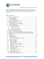
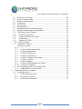
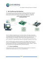
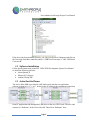
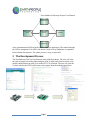
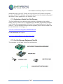

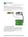
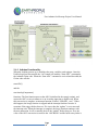
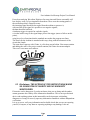

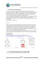
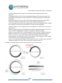
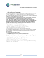
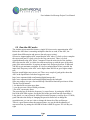
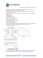


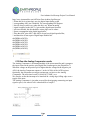
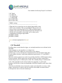
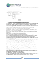
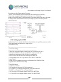


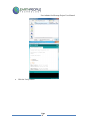
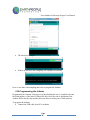
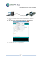

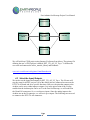
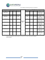
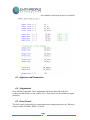
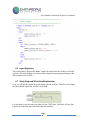
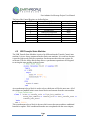
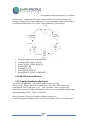

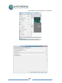

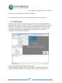
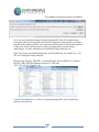
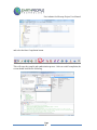
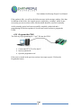
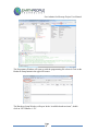
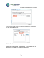

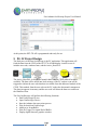
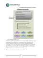
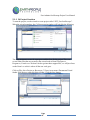
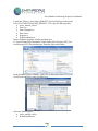

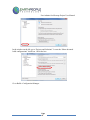
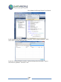
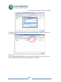
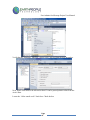
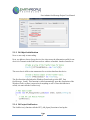
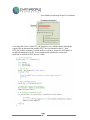
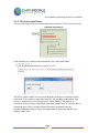

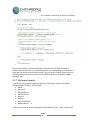

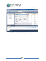
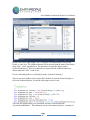
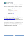
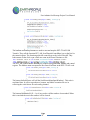
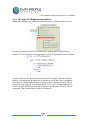
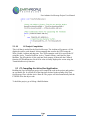
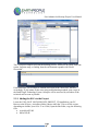
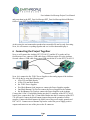
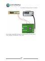
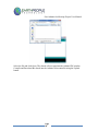
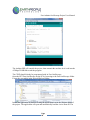
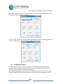


![BM-135-web [ 1289 Ko ]](http://vs1.manualzilla.com/store/data/006445734_1-a24d57c0d44cf0bdb6234ffbccd2c998-150x150.png)