1
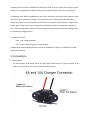
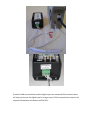
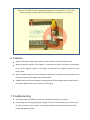
User M anual for EM C Series Charger 1. Overview The EMC series chargers are suitable for charging lithium ion battery packs such as those used in electric vehicle applications. The EMC series chargers are designed to work seamlessly with Elite Power ^ŽůƵƚŝŽŶƐ͛ŶĞƌŐLJDĂŶĂŐĞŵĞŶƚ^LJƐƚĞŵƚŚƌŽƵŐŚƚŚĞEŝŶƚĞƌĨĂĐĞ or digital input for safe battery charging. Standard safety features include protection against a short circuit on the charger output, reverse polarity, over charging, over temperature, etc. 2. Technical Parameters 2.1 Specifications Model: EMCXX-‐YY (XX: Output Voltage, YY: Output Amps) Efficiency: ≥88% Input voltage: 110V AC (220V AC available as special order) Input voltage range: AC 95 ~ 130V / AC 195 ~ 242V Frequency: 40 ~ 60Hz Communication: CAN and 12V Digital Input Vibration: SAEJ1378 Water resistance: IP31 Power factor: ≥0.75 2.1 Operating Environment Altitude: Temperature: ≤2000 Meters -‐30°C ~ 55°C Installation Stress: ≤ level 5 Humidity: 5% ~ 70% RH ʹ Non Condensing, keep away from exposure to moisture Storage environment: -‐30°C ~ 60°C ʹ Keep away from combustible materials 3. Charging Status and Alarm Status Indication 3.1 Alarm Indication Reverse polarity or low voltage: Red light blinking, 20% light on Charger over heating: Red light blinking, 40% light on Ambient temperature too high: Red light blinking, 60% light on Charging time out: Red light blinking, 80% light on Over Voltage Protection: Red light blinking, 100% lights on BMS alarm/charging interruptions ůů>͛ƐďůŝŶŬŝŶŐ 3.2 Charging Status Indication Shutdown status: Six lights blinking Charging stage: Percent light indicating pack voltage vs. max charging -‐ voltage Battery presence not detected: Red light blinking, 20% light on Charging complete: All green lights on 4. Functions 4.1 Output short circuit protection. 4.2 Over-‐temperature protection: Temperature less than 83°C ʹ Full charging power Temperature is 85°C to 95°C ʹ Power reduced to 50% Temperature is greater than 95°C ʹ No output 4.3 Reverse polarity protection: charger will not turn on if the battery pack is connected backwards (or less than 5V). 4.4 A switch on the charger ŵĂƌŬĞĚ͞KǀĞƌƌŝĚĞ͟ŝƐƵƐĞĚ to select either external or internal controlled charging. Override Off ʹ Use with EMS system, either CAN or digital input Override On ʹ Charger program based on pack voltage only (recommended for testing purposes only, do not use for normal charging). 4.5 When external control is selected and a CAN signal is used, if any cell reaches the recharge set point (default 3.7V as signaled by the EMS) the charger will automatically enter the final recharge cycles. 4.6 Recharge cycles. When the EMS detects any cell has reached the recharge set point (default 3.7V) or above, the charger reduces the charge current to zero amps for five minutes to allow the EMS to balance the battery pack. The charge will resume after five minutes at half the previous charge current and will again charge until it receives a signal from the EMS that a cell has reached the recharge set point. These recharge cycles continue until the charging current reaches the minimum charging current to complete the charging process. 4.7 Digital alarm input: 0.0V ʹ 2.0V: Charging stopped 2.5V ʹ 12.0V: Enable charging or resume charging 4.8 When both CAN and the digital control signals are available the charger is controlled by the CAN communication signal. 5. Connections 5.1 IEC Connector For EMC chargers which output 10A or less the charger comes with an IEC type connector for the output. The connections to the battery pack are made as follows: 5.2 Anderson SB50 Connector EMC Chargers with output greater than 10A come with an Anderson SB50 style connector ĨŽƌƚŚĞŽƵƚƉƵƚ͘dŚĞƐĞĐŽŶŶĞĐƚŽƌƐĂƌĞůĂďĞůĞĚ͞н͟ĂŶĚ͞-‐͘͞ŵĂƚŝŶŐĐŽŶŶĞĐƚŽƌĐŽŵĞƐǁŝƚŚ the charger. -‐ + 5.3 CAN and Digital Input Controls A five wire connector connects to the charger for interfacing with the BMS. Three wires have a white connector attached, these three wires are the CAN interface. The other two ǁŝƌĞƐĂƌĞůĂďĞůĞĚ͞нϭϮs͟ĂŶĚ͞-‐ ϭϮs͕͟ƚŚĞƐĞǁŝƌĞƐĂƌĞƚŚĞĚŝŐŝƚĂůŝŶƉƵƚƵƐĞĚƚŽĐŽŶƚƌŽůƚŚĞ ĐŚĂƌŐĞƌĨƌŽŵƚŚĞD^Wh͘ŽŶŶĞĐƚƚŚĞ͞нϭϮs͟ƚŽƚŚĞKsĐŽŶŶĞĐƚŝŽŶŽŶƚŚĞD^WhĂŶĚ ƚŚĞ͞-‐ ϭϮs͟ƚŽƚŚĞ'EĐŽŶŶĞĐƚŝŽŶŽŶƚŚĞD^Wh͘ dŚĞD^WhǁŝůůŽƵƚƉƵƚĂϭϮǀŽůƚƐŝŐŶĂůĨƌŽŵƚŚĞ͞Ks͟ƚĞƌŵinal whenever a pack normal situation is detected. During charging if a cell exceeds the maximum voltage limit this will drop to 0 volts which will trigger the charger to temporarily pause charging until the high voltage cell can return to a normal voltage͘ůůŐƌĞĞŶ>͛ƐŽŶƚŚĞĐŚĂƌŐĞƌǁŝůůĨůĂƐŚǁŚĞŶ this occurs. 12V-‐ ŽŶŶĞĐƚƐƚŽ͞'E͟ ϭϮsнŽŶŶĞĐƚƐƚŽ͞Ks͟ For a CAN communication connection connect the CANH, CANL and CAN GND to the matching connection on the CAN connection on the EMS CPU. The white connector may be cut off of the cable; however, note which wires are which before doing so. CANH CANL CAN GND If both the CAN communication and the digital inputs are connected CAN communications will take priority over the digital input for charge control. CAN communications requires the optional CAN board be installed on the EMS CPU. ΎĂƵƚŝŽŶΎdŚĞD^WhŚĂƐĂƉƌŽŐƌĂŵŵŝŶŐƉŽƌƚŽŶŝƚŵĂƌŬĞĚ͞Zdž͕ddž͕Z^͕s^^͘͟ Do not attempt connect the CAN communication connection to this port! 6. Cautions Make sure charger voltage output matches to the number of cells in the battery pack. Make sure positive output of the chargers is connected to a positive connection to the battery pack, and the negative output of the charger is connected to a negative connection of the battery pack. After a complete charge, disconnect the power source from the charger and then disconnect the connection between the charger and the battery pack. A BMS system must be used during the charging process either through CAN communication or through the digital alarm input to prevent over-‐charging. 7. Troubleshooting The charger must be installed in a cool well-‐ventilated area which is free of dust If the charger is not charging unplug the charger from the AC line and battery pack, then check for poor connections, short circuits, over heating conditions as well as alarm status from the Energy Management System. /ĨĐŚĂƌŐĞƌĚŽĞƐŶŽƚĚŝƐƉůĂLJĂŶLJ>͛ƐǁŚĞŶƉůƵŐŐĞĚŝŶĂŶĚĐŚĂƌŐŝŶŐĚŽĞƐŶŽƚŽĐĐƵƌƚŚĞĨƵƐĞŵĂLJ be blow. Unplug the charger from the battery pack and AC line and check the fuse by unscrewing the cap with a #2 Philips screw driver. If the fuse is blown replace with an equivalent size fuse of the same voltage and amperage rating. If the charger finishes charging too early make sure that the connection from the charge to the battery pack is good and does not have high resistance.