1
UM1866
User manual
Getting started with the osxMotionFx fusion and compass library
for X-CUBE-MEMS1 expansion for STM32Cube
Introduction
This user manual describes the osxMotionFX fusion and compass calibration library. The osxMotionFX
suite is filtering and predictive software. It uses advanced algorithms to integrate outputs from multiple
MEMS sensors in a "smart" way, independent of environmental conditions, to reach optimum
performance. osxMotionFX is an add-on software package for the X-CUBE-MEMS1 expansion for
STM32Cube. This manual also provides an overview of the sample application using the library APIs
and running on the STM32 Nucleo equipped with the X-NUCLEO-IKS01A1 expansion board. Finally, it
presents an overview of the software installer used to install the software package on a Windows PC.
The software is based on STM32Cube technology and expands STM32Cube-based packages.
Information about STM32Cube is available on www.st.com at: http://www.st.com/stm32cube.
October 2015
DocID027533 Rev 3
1/35
www.st.com
Contents
UM1866
Contents
1
osxMotionFX library add-on of X-CUBE-MEMS1 software,
expansion for STM32Cube ..................................................................... 3
1.1
Overview .......................................................................................... 3
1.2
Architecture ...................................................................................... 3
1.3
Folders structure .............................................................................. 4
1.4
APIs ................................................................................................. 5
1.5
Sample application description......................................................... 5
1.6
2
1.5.1
6-axis and 9-axis sensor fusion osxMotionFX library ........................ 5
1.5.2
Sensors calibration in the osxMotionFX library ................................. 9
Sensor data logging utility .............................................................. 11
System setup guide...................................................................... 20
2.1
Hardware Description ..................................................................... 20
2.1.1
STM32 Nucleo platform ................................................................... 20
2.1.2
X-NUCLEO-IKS01A1 expansion board ........................................... 20
2.2
Software description ....................................................................... 22
2.3
Hardware and software setup ........................................................ 22
2.3.1
Hardware setup ............................................................................... 22
2.3.2
Software Setup ................................................................................ 22
2.3.3
Development tool-chains and compilers ......................................... 22
2.3.4
PC utility .......................................................................................... 22
2.3.5
System setup guide ......................................................................... 23
2.3.6
STM32 Nucleo and Sensor expansion boards setup ...................... 23
2.3.7
Sensors_DataLog GUI setup .......................................................... 23
2.3.8
osxMotionFX installer setup ............................................................ 23
2.3.9
osx License wizard .......................................................................... 26
3
Acronyms and abbreviations ...................................................... 32
4
References .................................................................................... 33
5
Revision history ........................................................................... 34
2/35
DocID027533 Rev 3
UM1866
osxMotionFX library add-on of X-CUBE-MEMS1
software, expansion for STM32Cube
1
osxMotionFX library add-on of X-CUBE-MEMS1
software, expansion for STM32Cube
1.1
Overview
The osxMotionFX library is a software package that expands the functionality provided by
X-CUBE-MEMS1 software.
The key features of the package are:
Complete middleware to build applications using temperature and humidity sensors
(HTS221), a pressure sensor (LPS25HB) and motion sensors (LIS3MDL and
LSM6DS0)
Gyroscope bias and magnetometer offset calibration routine
osxMotionFX (iNEMOEngine PRO) real-time motion sensor data fusion (under
OPEN.MEMS license)
Easy portability across different MCU families, thanks to STM32Cube
Sample application to transmit real-time sensor and sensor fusion data to a PC
Sample implementation available on board X-NUCLEO-IKS01A1 when connected to
NUCLEO-F401RE or NUCLEO-L476RG
The osxMotionFX (iNEMOEngine PRO) suite is filtering and predictive software. It uses
advanced algorithms to integrate outputs from multiple MEMS sensors in a "smart" way,
independent of environmental conditions, to reach optimum performance.
The software comes with a sample application running on X-NUCLEO-IKS01A1, when
connected to a NUCLEO-F401RE or a NUCLEO-L476RG.
1.2
Architecture
This software is an expansion for X-CUBE-MEMS1 software.
The package extends STM32Cube by providing a middleware component for the
osxMotionFX library.
The software layers used by the application software to access and use the sensor
expansion board are the following:
STM32Cube HAL layer: The HAL driver layer provides a generic multi-instance simple
set of APIs (application programming interfaces) to interact with the upper layers
(application, libraries and stacks). It is composed of generic and extension APIs. It is
directly built around a generic architecture and allows the layers that are built upon,
such as the middleware layer, to implement their functionalities without dependencies
on the specific hardware configuration for a given microcontroller unit (MCU). This
structure improves library code reusability and guarantees easy portability to other
devices.
Board support package (BSP) layer: The software package needs to support the
peripherals on the STM32 Nucleo board apart from the MCU. This software is
included in the board support package (BSP). This is a limited set of APIs which
provides a programming interface for certain board specific peripherals, e.g. the LED,
user button, etc. This interface also helps in identifying the specific board version. If
the sensor expansion board is used, it provides the programming interface for various
inertial and environmental sensors. It provides support for initializing and reading
sensor data.
DocID027533 Rev 3
3/35
osxMotionFX library add-on of X-CUBE-MEMS1
software, expansion for STM32Cube
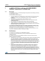
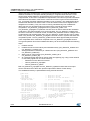
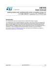
The diagram below outlines the software architecture of the package:
UM1866
Figure 1: osxMotionFX plus X-CUBE-MEMS1 software architecture
1.3
Folders structure
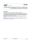
This section provides an overview of the package folders structure.
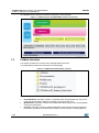
The image below outlines the architecture of the package
Figure 2: osxMotionFX package folder structure
The following folders are included in the software package:
4/35
Documentation: this folder contains a compiled HTML file generated from the source
code and documenting in detail the software components and APIs.
Middlewares: this folder contains the osxMotionFX library binary code, documentation
and license information.
Projects: this folder contains a sample application used to access sensor and sensor
fusion data, provided for the NUCLEO-F401RE and the NUCLEO-L476RG platforms
DocID027533 Rev 3
UM1866
1.4
osxMotionFX library add-on of X-CUBE-MEMS1
software, expansion for STM32Cube
with three development environments (IAR Embedded Workbench for ARM, RealView
Microcontroller Development Kit (MDK-ARM), System Workbench for STM32).
APIs
Detailed technical information about the APIs of osxMotionFX and compass calibration
libraries can be found in a compiled HTML file, named OSXMotionFX_Package.chm, and
located in the Documentation folder of the software package, where all the functions and
parameters are fully described.
The osxMotionFX engine is provided as a node-locked library which allows derivative
firmware images to run on a specific STM32 Nucleo device only. Licensing activation codes
must to be requested from ST and included in the project (and will become part of the build
process) prior to attempting its usage. The resulting firmware binary image will therefore be
node-locked.
For complete information about the open.MEMS license agreement, please refer to the
license file located in the Middlewares/ST/STM32_OSX_MotionFX_Library folder.
1.5
Sample application description
A sample application of osxMotionFX fusion and compass calibration using the sensor
expansion board with the NUCLEO-F401RE board or the NUCLEO-L476RG board can be
found into the Projects folder of the software package.
In this application, sensor and sensor fusion data are transmitted in real-time from the
Nucleo board to PC via UART interface. Transmitted data can be viewed using
Sensors_DataLog application, a PC-based application developed by STMicroelectronics
included in the X-CUBE-MEMS1 package (refer to section 1.6 for detailed usage of utility)
that reads and visualizes the sensors data and the sensor fusion data. For more
information about MotionFX engine refer to paragraph 1.5.1.
When the board is powered on, the compass is not calibrated. When the compass is not
calibrated, LED2 (green LED) of the Nucleo board is off. In order to calibrate the compass,
press the user button on the Nucleo board and perform the 8-movement calibration (see
paragraph 1.5.2 for details). You can calibrate the compass only when the sensor fusion is
activated (press the "Start Sensor Fusion" button on the PC GUI). When the calibration is
done, LED2 turns on and the compass points to the north.
By default, the calibration data is stored in RAM memory in order to be preserved when the
board is reset. It is also possible to store calibration data in Flash memory. To do this, you
need to compile the sample application "DataLogFusion" defining
"OSXMOTIONFX_STORE_CALIB_FLASH" in the project.
By default, the application uses the fusion 9X (accelerometer + gyroscope +
magnetometer). You can switch dynamically from fusion 9X to fusion 6X (accelerometer +
gyroscope), pushing the apposite button on the “Sensors_DataLog” GUI. When using the
fusion 6X, the compass calibration is no longer required.
1.5.1
6-axis and 9-axis sensor fusion osxMotionFX library
The osxMotionFX library implements sensor fusion algorithm for estimation of 3D
orientation in space. It uses digital filter based on Kalman theory to fuse data from several
sensors. Using this method it compensates for limitations of single sensors. For instance a
gyroscope suffers from data drift that can affect the orientation estimation. This can be
fixed by using the magnetometer that provides absolute orientation value. On the contrary
magnetometer has not a very high bandwidth and suffers of magnetic disturbance; all these
weaknesses can be compensated through the usage of gyroscope. 9-axis sensor fusion
DocID027533 Rev 3
5/35
osxMotionFX library add-on of X-CUBE-MEMS1
UM1866
software, expansion for STM32Cube
utilizes data from accelerometer, gyroscope and magnetometer (A+G+M) and provides
absolute orientation in 3D space including heading i.e. magnetic North direction. 6-axis
sensor fusion utilizes data from accelerometer and gyroscope (A+G), it does not use
magnetometer. It has lower computational requirements, but it does not provide information
about absolute orientation of the device. 6-axis sensor fusion is good for fast movements
(e.g. for gaming) and when absolute orientation is not necessary. The osxMotionFX library
contains both 6 and 9-axis sensor fusion. 6-axis and 9-axis sensor fusion algorithms are
integrated in one library. They can even be running simultaneously.The osxMotionFX
library has two very important internal functions which execute the sensor fusion
computation: osx_MotionFX_propagate and osx_MotionFX_update. The
osx_MotionFX_propagate is a prediction function and it is used to estimate the orientation
in 3D space. This phase weights more gyroscope data. The osx_MotionFX_update is the
function of correction. It is used to correct, if needed, the prediction solution. It weighs more
accelerometer and magnetometer data. The osx_MotionFX_update function can be called
either every time the osx_MotionFX_propagate is invoked or less in systems that have less
computation power. The osx_MotionFX_update function takes approximately three times
more computation time of the MCU compared to the osx_MotionFX_propagate function.
The typical operation flow of the osxMotionFX library can be summarized with the following
steps:
1.
2.
3.
4.
5.
Initialize sensors
Initialize the sensor fusion library and calibration library (osx_MotionFX_initialize and
osx_MotionFX_compass_init)
Setup parameters of the library in a Knobs structure (osx_MotionFX_getKnobs and
osx_MotionFX_setKnobs)
Start 6-axis or 9-axis engine (osx_MotionFX_enable_6X or
osx_MotionFX_enable_9X)
At a selected output data rate of sensor fusion do regularly (e.g. using a timer of MCU
or data ready signal from one of the sensors):
Read and convert data from sensors
Call osx_MotionFX_propagate
Call osx_MotionFX_update
Both osx_MotionFX_propagate and osx_MotionFX_update functions take as an input
sensor data and both of them also provide output data of Sensor Fusion library.
The osxMotionFX library is parameterized using a Knobs structure:
typedef struct
{
float ATime;
float MTime;
float FrTime;
accelerations occurs */
unsigned char LMode;
*/
float gbias_mag_th_sc_6X;
float gbias_acc_th_sc_6X;
float gbias_gyro_th_sc_6X;
float gbias_mag_th_sc_9X;
float gbias_acc_th_sc_9X;
float gbias_gyro_th_sc_9X;
unsigned char modx;
/*
/*
/*
merge rate to the accel
merge rate to the mag
merge rate to the accel when external
/*
gyro bias learn mode,
1-static learning
2-dynamic learning
/*
/*
/*
/*
/*
/*
scaler
scaler
scaler
scaler
scaler
scaler
smartphone/tablet
char acc_orientation[QNUM_AXES];
char gyro_orientation[QNUM_AXES];
char mag_orientation[QNUM_AXES];
osxMFX_Engine_Output_Ref_Sys output_type;
int start_automatic_gbias_calculation;
} osxMFX_knobs;
6/35
*/
*/
/*
/*
/*
/*
for
for
for
for
for
for
the
the
the
the
the
the
/*
gyro bias mag threshold
gyro bias mag threshold
gyro bias mag threshold
gyro bias mag threshold
gyro bias mag threshold
gyro bias mag threshold
setting to indicate the
set to 1 in
nominal
*/
nominal
*/
nominal
*/
nominal
*/
nominal
*/
nominal
*/
decimation,
set to >=1 in embedded solutions */
accelerometer data orientation
*/
gyroscope data orientation
*/
magnetometer data orientation
*/
0: NED, 1: ENU
*/
DocID027533 Rev 3
UM1866
osxMotionFX library add-on of X-CUBE-MEMS1
software, expansion for STM32Cube
ATime, MTime and FrTime represent the weighting stability of sensors in prediction
(trust to the sensor); they can be a value from 0 to 1; it is recommended to keep
default values
LMode represents the gyroscope bias learning mode; the library automatically tracks
and calibrates gyro zero-rate bias drift; the possible values of this parameter are:
LMode = 0 – learning off: This mode can be used in case gyro is already
calibrated
LMode = 1 – static learning: Learning is performed only when the system is not
moving
LMode = 2 – dynamic learning: Learning is performed also when the system is
moving
gbias_xxx_th_sc represent the thresholds that define when the gbias algorithm
automatically starts. In fact if the data for each axis are below those thresholds, the
algorithm for gbias calculation is executed. They should be found by testing (they are
different for different part numbers). Values in example project are usually correct
modx represents the decimation of osx_MotionFX_update call frequency. See
resources optimization paragraph below for more details
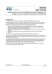
acc_orientation, gyro_orientation, mag_orientation represent the arrays of 3
characters describing orientation of sensor axis x, y and z. The possible values are: n
(north), e (east), s (south), w (west), u (up), d (down). An example is shown in Figure
3: "Example of x, y, z axis values":
output_type represents the Sensor Fusion library output orientation: 0 means NED, 1
means ENU
start_automatic_gbias_calculation represents a flag that restarts gyroscope bias
calibration when set to 1
Figure 3: Example of x, y, z axis values
As shown in the Figure 3: "Example of x, y, z axis values" first sensor (magnetometer) is
oriented SEU (x - South, y - East, z - Up) while the second (accelerometer + gyroscope) is
ENU (x - East, y - Nor th, z - Up).
The osx_MotionFX_propagate and the osx_MotionFX_update functions expect input from
sensors in osxMFX_input structure:
DocID027533 Rev 3
7/35
osxMotionFX library add-on of X-CUBE-MEMS1
software, expansion for STM32Cube
typedef struct
{
float mag[NUM_AXES];
float acc[NUM_AXES];
float gyro[NUM_AXES];
} osxMFX_input;
UM1866
/*
/*
/*
calibrated mag [uT]/5
0
acc [g]
gyro [dps]
*/
*/
*/
mag represents magnetometer data after calibration in µT/50
acc represents accelerometer data in g
gyro represents gyroscope data in dps
The osx_MotionFX_propagate and the osx_MotionFX_update functions provide output of
the sensor fusion in osxMFX_output structure:
typedef struct
{
float rotation_9X[NUM_AXES] ;
float quaternion_9X[QNUM_AXES] ;
float gravity_9X[NUM_AXES] ;
float linear_acceleration_9X[NUM_AXES] ;
float heading_9X;
… similarly for 6-axis SF
/*
/*
/*
/*
/*
9 axes yaw, pitch and rol l
9 axes quaternio n
9 axes device frame gravity
9 axes device frame lin acce l
9 axes headin g
*/
*/
*/
*/
*/
} osxMFX_output;
rotation represents the orientation of the system in three angles format: yaw, pitch and
roll
quaternion represents orientation of the system in four numbers format; this format
gives the same information as rotation; it has advantages for computation and
therefore it is usually used by other algorithms (which can follow the sensor fusion)
gravity represents the static acceleration (i.e. Earth’s gravity) vector extracted from
acceleration data
linear_acceleration represents the dynamic acceleration (i.e. movement) vector
extracted from acceleration data
heading represents the direction to the magnetic North
Based on practical experience, it is recommended to use 100 Hz as output data rate for the
sensor fusion library. For this reason it is important to set-up adequately the output data
rate of the sensors. The gyroscope and the accelerometer should use an output data rate
more than 100 Hz. The magnetometer can be set to a lower output data rate (i.e. an output
data rate of 20/40 Hz is typically good for LIS3MDL sensor).
The osxMotionFX library is capable to compute both 6-axis and 9-axis sensor fusion. It can
even do it in parallel. The library parameters structure osxMFX_knobs and the library
output structure osxMFX_output have several fields which are dedicated to 6-axis and 9axis respectively. It is only necessary to enable the desired 6-axis or 9-axis operation by
calling osx_MotionFX_enable_6X or osx_MotionFX_enable_9X respectively. For 6-axis
sensor fusion, magnetometer data are not required.
It is possible to scale the system requirements of the library in terms of MCU/MPU load.
The osx_MotionFX_update function is a correction step in the Sensor Fusion algorithm. It
requires approximately three times more computation power than
osx_MotionFX_propagate function. If systems resources are limited (e.g. in embedded
system) this function does not need to be called at the same frequency as the output data
rate of the library. Using modx parameter in osxMFX_knobs structure, it is possible to
decrease frequency of osx_MotionFX_update function calls. For example, it is possible to
set modx equals to 2. Then the osx_MotionFX_propagate function will be called at the
output data rate of the Sensor Fusion and the osx_MotionFX_update function will be called
8/35
DocID027533 Rev 3
UM1866
1.5.2
osxMotionFX library add-on of X-CUBE-MEMS1
software, expansion for STM32Cube
only after every second osx_MotionFX_propagate function call. For tablet or other system
with MCU/MPU you can set modx to 1, for STM32F4 you can set modx to 1 and for
STM32F1 you can set the modx to 2. The library can be used on Cortex-M0 (e.g.
STM32L0) as well.
Sensors calibration in the osxMotionFX library
STMicroelectronics produces its sensors with high effort for a precise operation. However
there are factors affecting operation of sensors that are often present only in final
application. These factors need to be evaluated by users. The osxMotionFX library
contains routines for calibration of magnetometer for hard iron effect and gyroscope
calibration routines.Hard-iron distortion is normally generated by ferromagnetic material
with permanent magnetic fields that are part of the object (e.g. a tablet) in use. These
materials could be permanent magnets or magnetized iron or steel. They are time invariant
and deform the local geomagnetic field with different offset on different directions.
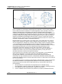
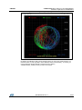
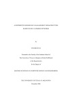
Generally, if the user performs many 3D rotations of the object in an ideal environment (no
hard-iron/soft-iron distortion) and plots the collected magnetic sensor raw data, the result
will be a perfect sphere with no offset.
Figure 4: Magnetometer data in ideal environment or after calibration
The hard-iron distortion effect is to offset the sphere along the x, y and z axes; in the x-y
plane, the hard-iron distortion is identified by an offset of the origin of the ideal circle from
(0, 0), scatter plots for XY and XZ axis are ok to see if there is an offset.
DocID027533 Rev 3
9/35
osxMotionFX library add-on of X-CUBE-MEMS1
software, expansion for STM32Cube
UM1866
Figure 5: Magnetometer data disturbed by hard-iron effect
Soft-iron distortion is generated by magnetically soft materials or current carrying PCB
traces. While the hard-iron distortion is constant regardless of the orientation, the soft-iron
distortion changes with the orientation of the object in the Earth’s field (soft magnetic
materials are changing their magnetization direction). Basically, the local geomagnetic field
is deformed with different gain on different directions. The effect of the soft-iron distortion is
to make the ideal full round sphere become a tilted ellipsoid; in the x-y plane, the soft-iron
distortion is identified by a tilted ellipse with the origin in (0,0) for XY axis (XZ). If PCB is
designed correctly, the soft iron effect is not present and therefore there is no need for soft
iron effect compensation (valid for X-NUCLEO-IKS01A1).
Magnetometer has an offset by itself. Then there can be, and usually there are, hard iron
and/or soft iron distortions. Hard iron effect is different from board to board – each board
can be magnetized in a different way. Soft iron effect is always equal for all (same) boards
– only one board can be characterized for soft iron and the result can be copied to the
other boards. Magnetometer calibration library is included in osxMotionFX library. If PCB is
well designed by taking into account the magnetometer placement (high current
traces/other components clearance) soft iron will not be present. For this reason
osxMotionFX library can compensate for hard iron effect only. When the calibration is
enabled user needs to cover as much as possible 3D sphere by moving the board,
otherwise there will be a drift in the output of the library.
Gyroscope has a zero-rate offset, which needs to be compensated. In the osxMotionFX
library there is estimation of gyroscope offset done automatically all the time.
Accelerometer calibration is not necessary for sensor fusion except for applications
demanding very high orientation precision. Accelerometer calibration requires placing the
system into a several positions perfectly aligned with direction of Earth gravity (see AN3182
for more information).
The osxMotionFX library includes the magnetometer calibration library, which compensates
the hard-iron distortions. The magnetometer calibration can be done periodically at a
slower frequency than sensor fusion output data rate (e.g. 25 Hz) and the flow can be
summarized as:
1.
2.
3.
10/35
Set input data from accelerometer and magnetometer to calibration library
(osx_MotionFX_compass_saveAcc and osx_MotionFX_compass_saveMag functions)
Call calibration function (osx_MotionFX_compass_run function)
Check if calibration was successful (osx_MotionFX_compass_isCalibrated function):
DocID027533 Rev 3
UM1866
osxMotionFX library add-on of X-CUBE-MEMS1
software, expansion for STM32Cube
4.
If it returns 1 then the calibration was successful and the results (magnetometer
offset) can be read by osx_MotionFX_getCalibrationData function
Otherwise it needs to repeat all the operations from step 1.
Apply calibration results:
MAG_Calibrated.AXIS_X = MAG_Value.AXIS_X - magOffset.magOffX;
MAG_Calibrated.AXIS_Y = MAG_Value.AXIS_Y - magOffset.magOffY;
MAG_Calibrated.AXIS_Z = MAG_Value.AXIS_Z - magOffset.magOffZ;
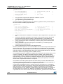
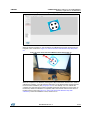
After initiating the calibration routine, the Nucleo board should be slowly rotated performing
a figure "6" movement in the 3D space. An example is shown in Figure 6: "Example of
rotation of the Nucleo board during calibration".
While performing this pattern, keep the Nucleo board clear of other magnetic objects such
as cell phones, computers and other steel objects. To be sure that calibration was done
properly it is recommended to check magnetometer data (after applying calibration results)
using two 2D plots (see Figure 4: "Magnetometer data in ideal environment or after
calibration" for an example of good calibration and Figure 5: "Magnetometer data disturbed
by hard-iron effect" for an example of bad calibration). Magnetometer calibration can be
restarted by calling osx_MotionFX_compass_forceReCalibration function.
Figure 6: Example of rotation of the Nucleo board during calibration
1.6
Sensor data logging utility
The X-CUBE-MEMS1 expansion for STM32Cube contains an utility for Windows PCs
called "Sensors_DataLog". This utility is available in the ROOT_DIR\Utilities\PC_software
folder.
This section describes the usage of the utility. Before using this utility, the user must ensure
that the necessary drivers, as explained in the section relating to system setup, are
installed and the expansion board along with NUCLEO-F401RE or NUCLEO-L476RG
board is connected to the PC.
DocID027533 Rev 3
11/35
osxMotionFX library add-on of X-CUBE-MEMS1
software, expansion for STM32Cube
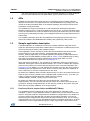
Please perform the following steps:
1
UM1866
Check the Windows "Device Manager" to note the ST COM port; for example in
Figure 7: "Device manager view in Windows" the port is COM13.
Figure 7: Device manager view in Windows
2
12/35
Launch Sensors_DataLog.exe and check if the COM device number for the current
expansion board is correct.
DocID027533 Rev 3
UM1866
osxMotionFX library add-on of X-CUBE-MEMS1
software, expansion for STM32Cube
Figure 8: Sensors_DataLog Utility snapshot 1
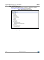
3
Select between various sensors (pressure, temperature, humidity, accelerometer,
gyroscope, magnetometer) available on the expansion board (see Figure 9:
"Sensors_DataLog Utility snapshot 2").
4
Set appropriate delay/interval in milliseconds between consecutive data points; the
default is 500 ms (see Figure 9: "Sensors_DataLog Utility snapshot 2")
DocID027533 Rev 3
13/35
osxMotionFX library add-on of X-CUBE-MEMS1
software, expansion for STM32Cube
UM1866
Figure 9: Sensors_DataLog Utility snapshot 2
14/35
5
Save the log in a file within the folder called "SensorsDataLog" using the "Save"
button, or clear it with the "Clear" button (see Figure 10: "Sensors_DataLog Utility
snapshot 3").
6
Check the "Plot" CheckBox to visualize the data log for the selected sensors (see
Figure 10: "Sensors_DataLog Utility snapshot 3").
DocID027533 Rev 3
UM1866
osxMotionFX library add-on of X-CUBE-MEMS1
software, expansion for STM32Cube
Figure 10: Sensors_DataLog Utility snapshot 3
7
Press Start, and data is displayed as shown in Figure 11: "Sensors_DataLog Utility
snapshot 4"
Figure 11: Sensors_DataLog Utility snapshot 4
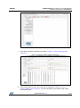
8
Press "Start Sensor Fusion" and a 3D cube is displayed as shown in Figure 12:
"Sensors_DataLog Utility snapshot 5". The cube animation is generated using sensor
fusion quaternions
DocID027533 Rev 3
15/35
osxMotionFX library add-on of X-CUBE-MEMS1
software, expansion for STM32Cube
UM1866
Figure 12: Sensors_DataLog Utility snapshot 5
9
Check the "Log" CheckBox in order to see the MEMS sensors data and the sensor
fusion data (quaternions and Euler angles) as shown in Figure 13: "Sensors_DataLog
Utility snapshot 6"
Figure 13: Sensors_DataLog Utility snapshot 6
1
0
16/35
Press “Switch to 6x Fusion” to pass dynamically from 9x fusion to 6x fusion as
shown in Figure 14: "Sensors_DataLog Utility snapshot 7". In order to come back to 9x
fusion you can press “Switch to 9x Fusion”.
DocID027533 Rev 3
UM1866
osxMotionFX library add-on of X-CUBE-MEMS1
software, expansion for STM32Cube
Figure 14: Sensors_DataLog Utility snapshot 7
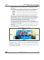
When the board is powered on, the compass is not calibrated so the cube could not point to
magnetic north. It is shown in Figure 15: "View of the board and Windows utility after power
on".
Figure 15: View of the board and Windows utility after power on
When the compass is not calibrated, LED2 (green LED) of the Nucleo board is off. In order to
calibrate the compass, you must press the user button on the Nucleo board and then perform
the 8 movement calibration (see paragraph 1.5.2 for more details). You can calibrate the
compass only when the sensor fusion is activated (press the "Start Sensor Fusion" button on
the PC GUI). When the calibration is completed, wait a few seconds until the cube shown in
the GUI points to north (see Figure 16: "View of the board and Windows utility after
calibration"). When the calibration is done, LED2 turns on.
DocID027533 Rev 3
17/35
osxMotionFX library add-on of X-CUBE-MEMS1
software, expansion for STM32Cube
UM1866
Figure 16: View of the board and Windows utility after calibration
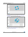
It is possible to check the quality of the magnetometer calibration, displaying the scatter plot
of the magnetometer. Press “Show Scatter Plot” as shown in Figure 17: "Sensors_DataLog
Utility snapshot 8" and you will see the magnetometer scatter plot as shown in Figure 18:
"Sensors_DataLog Utility magnetometer scatter plot".
Figure 17: Sensors_DataLog Utility snapshot 8
18/35
DocID027533 Rev 3
UM1866
osxMotionFX library add-on of X-CUBE-MEMS1
software, expansion for STM32Cube
Figure 18: Sensors_DataLog Utility magnetometer scatter plot
By default, the calibration data is stored in RAM memory in order to be preserved when you
reset the board. It is also possible to store calibration data in Flash memory. To do this, you
must compile the sample application "DataLogFusion" defining
"OSXMOTIONFX_STORE_CALIB_FLASH" in the project.
DocID027533 Rev 3
19/35
System setup guide
UM1866
2
System setup guide
2.1
Hardware Description
This section describes the hardware components needed for developing a sensor-based
application.
The sub-sections that follow describe the individual components.
2.1.1
STM32 Nucleo platform
The STM32 Nucleo boards provide an affordable and flexible way for users to try out new
ideas and build prototypes with any STM32 microcontroller lines. The Arduino™
connectivity support and ST morpho headers make it easy to expand the functionality of
the STM32 Nucleo open development platform with a wide choice of specialized expansion
boards. The STM32 Nucleo board does not require any separate probes as it integrates the
ST-LINK/V2-1 debugger/programmer. The STM32 Nucleo board comes with the STM32
comprehensive software HAL library together with various packaged software examples.
Information about the STM32 Nucleo boards is available on st.com at:
http://www.st.com/stm32nucleo
Figure 19: STM32 Nucleo board
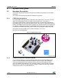
2.1.2
X-NUCLEO-IKS01A1 expansion board
The X-NUCLEO-IKS01A1 is a sensor expansion board for use with the STM32 Nucleo
system. It is also compatible with Arduino UNO R3 connector layout, and is designed
around the STMicroelectronics humidity (HTS221), pressure (LPS25HB) and motion
sensors (LIS3MDL and LSM6DS0). The X-NUCLEO-IKS01A1 interfaces with the STM32
MCU via I2C pin, and the user can change the default I2C address and the device IRQ by
changing one resistor on the evaluation board.
20/35
DocID027533 Rev 3
UM1866
System setup guide
Figure 20: X-NUCLEO-IKS01A1 sensor expansion board
Information about the X-NUCLEO-IKS01A1 expansion board is available on st.com at:
http://www.st.com/x-nucleo
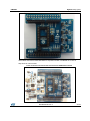
Figure 21: Sensor expansion board connected to STM32 Nucleo board
DocID027533 Rev 3
21/35
System setup guide
2.2
UM1866
Software description
The following software components are needed in order to set up a suitable development
environment for creating applications using the osxMotionFX library for the STM32 Nucleo,
equipped with the sensor expansion board:
2.3
X-CUBE-MEMS1: an expansion for STM32Cube dedicated to sensor application
development. The X-CUBE-MEMS1 firmware and related documentation is available
on st.com.
osxMotionFX: an add-on software package for X-CUBE-MEMS1 that provides fusion
and compass calibration APIs. The osxMotionFX firmware and related documentation
is available on st.com.
Development tool-chain and compiler: The STM32Cube expansion software supports
the following three environments:
IAR Embedded Workbench for ARM® (EWARM) toolchain + ST-LINK
RealView Microcontroller Development Kit (MDK-ARM) toolchain + ST-LINK
System Workbench for STM32
Hardware and software setup
This section describes the hardware and software setup procedures and required system
setup.
2.3.1
Hardware setup
The following hardware components are required:
1.
2.
3.
2.3.2
One STM32 Nucleo development platform (suggested order code: NUCLEO-F401RE
or NUCLEO-L476RG)
One sensor expansion board (order code: X-NUCLEO-IKS01A1)
One USB type A to Mini-B USB cable to connect the STM32 Nucleo to the PC
Software Setup
This section lists the minimum requirements for the developer to set up the SDK, run the
sample testing scenario based on the GUI utility and customize applications.
2.3.3
Development tool-chains and compilers
Please select one of the integrated development environments supported by the
STM32Cube expansion software, and read the system requirements and setup information
provided by the selected IDE provider.
2.3.4
PC utility
The Sensors_DataLog utility for PC has following minimum requirements:
22/35
PC with Intel or AMD processor running one of the following Microsoft operating
systems:
Windows XP SP3
Windows Vista
Windows 7
At least 128 MBs of RAM
2 X USB ports
40 MB of hard disk space
DocID027533 Rev 3
UM1866
2.3.5
System setup guide
System setup guide
This section describes how to set up different hardware components before writing and
executing an application on the STM32 Nucleo board with the sensor expansion board.
2.3.6
STM32 Nucleo and Sensor expansion boards setup
The STM32 Nucleo board integrates the ST-LINK/V2-1 debugger/programmer. The
developer can download the relevant version of the ST-LINK/V2-1 USB driver by accessing
the STSW-LINK008 or STSW-LINK009 on www.st.com (according to which Microsoft
Windows OS is used).
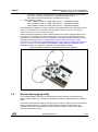
The sensor expansion board X-NUCLEO-IKS01A1 can be easily connected to the STM32
Nucleo motherboard through the Arduino UNO R3 extension connector, see Figure 21:
"Sensor expansion board connected to STM32 Nucleo board". The sensor expansion
board is capable of interfacing with the external STM32 microcontroller on the STM32
Nucleo via an inter-integrated circuit (I²C) transport layer.
2.3.7
Sensors_DataLog GUI setup
The Sensors_DataLog GUI included in the X-CUBE-MEMS1 software package is a
graphical user interface that can be used to interact and obtain sensor and sensor fusion
data. Please see section 1.6 for a description of the how this PC utility works.
This utility retrieves sensor data from the connected STM32 Nucleo board and displays it in
a tabular form, and graphically as well.
In order to use the Sensors_DataLog GUI, make sure you have correctly set up your
hardware and software.
The utility can be launched by simply double-clicking on the Sensors_DataLog.exe file,
located in the "Utilities\PC_software\Sensors_DataLog" folder.
2.3.8
osxMotionFX installer setup
The osxMotionFX software package is provided with a Windows installer
(osxMotionFX_Setup_vXXX.exe), that guides the user in the correct installation of the
software package. The installer also includes the osx License Wizard tool which allows the
user to automatically obtain a valid node-locked license for their Nucleo board. The installer
of this wizard is described in the paragraph 2.3.9.
Before running the installer, you need to download the latest release of the X-CUBEMEMS1 software package and unzip this package in your workspace. For example, if you
have the X-CUBE-MEMS1 package in
"C:\workspace\STM32CubeExpansion_MEMS1_VX.X.X", at this point you can run the
installer and see the welcome window as shown in Figure 22: "osxMotionFX installer
snapshot 1".
DocID027533 Rev 3
23/35
System setup guide
UM1866
Figure 22: osxMotionFX installer snapshot 1
You must then accept the license agreement as shown in Figure 23: "osxMotionFX installer
snapshot 2".
Figure 23: osxMotionFX installer snapshot 2
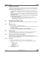
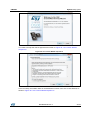
The installer provides some information, such as the requirements of the latest release of
the X-CUBE-MEMS1 software package (see Figure 24: "osxMotionFX installer snapshot
3").
24/35
DocID027533 Rev 3
UM1866
System setup guide
Figure 24: osxMotionFX installer snapshot 3
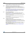
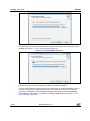
In the next step, the installer asks for the destination location of the osxMotionFX library, as
shown in Figure 25: "osxMotionFX installer snapshot 4"
Figure 25: osxMotionFX installer snapshot 4
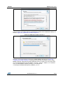
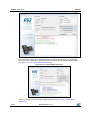
After this, you must provide the path to the X-CUBE-MEMS1 package (see Figure 26:
"osxMotionFX installer snapshot 5"). Remember to insert the correct path to the X-CUBEMEMS1 package, otherwise the sample application will not compile. This is the path where
you can locate the folders "Documentation", "Projects", "Drivers", "Utilities", etc. contained
in the X-CUBE-MEMS1 software package. In our example it is
"C:\workspace\STM32CubeExpansion_MEMS1_V1.2.0".
DocID027533 Rev 3
25/35
System setup guide
UM1866
Figure 26: osxMotionFX installer snapshot 5
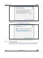
In the next step, you must provide the path to the Start menu folder where the shortcuts are
installed (see Figure 27: "osxMotionFX installer snapshot 6").
Figure 27: osxMotionFX installer snapshot 6
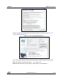
After this point the osxMotionFX installer can finish the software installation.
2.3.9
osx License wizard
This tool allows the user to automatically obtain a valid node-locked license for their Nucleo
board. You can see in Figure 28: "osx License Wizard snapshot 1" the welcome window.
26/35
DocID027533 Rev 3
UM1866
System setup guide
Figure 28: osx License Wizard snapshot 1
You need to accept the license agreement as shown in Figure 29: "osx License Wizard
snapshot 2".
Figure 29: osx License Wizard snapshot 2
In the next step, the installer asks for the destination location of the osx License Wizard, as
shown in Figure 30: "osx License Wizard snapshot 3".
DocID027533 Rev 3
27/35
System setup guide
UM1866
Figure 30: osx License Wizard snapshot 3
In the next step you must provide the path to the Start menu folder where the shortcuts are
installed (see Figure 31: "osx License Wizard snapshot 4").
Figure 31: osx License Wizard snapshot 4
After this step, the osx License Wizard can finish the software installation.
The osx License Wizard needs to access some information on the Nucleo board in order to
create the request for the node-locked license. For this reason the osx License Wizard
asks for the installation of some additional packages ("Microsoft VS 2013 redistributable"
and "STM32 ST-LINK Utility"), if you have not already installed them (see Figure 32: "osx
License Wizard snapshot 5".
28/35
DocID027533 Rev 3
UM1866
System setup guide
Figure 32: osx License Wizard snapshot 5
Before starting the osx License Wizard, you must connect via USB cable the Nucleo board
that you want to link to the node-locked license. Then, you can run the osx License Wizard.
First, you need to select the library you want to activate as shown in Figure 33: "osx
License Wizard snapshot 6".
Figure 33: osx License Wizard snapshot 6
The next step is to identify the Nucleo board plugged into your PC. To do this, you can
press the "Identify STM32 Nucleo board" button (see Figure 34: "osx License Wizard
snapshot 7").
DocID027533 Rev 3
29/35
System setup guide
UM1866
Figure 34: osx License Wizard snapshot 7
At this point you should see information about your Nucleo board. Then, you should edit
the "User name", "Company" and "Email" forms and press the "Generate license request"
(see Figure 35: "osx License Wizard snapshot 8").
Figure 35: osx License Wizard snapshot 8
Then, you should accept the license agreement (see Figure 36: "osx License Wizard
snapshot 9").
30/35
DocID027533 Rev 3
UM1866
System setup guide
Figure 36: osx License Wizard snapshot 9
Finally, you press the "Send license request email" button as shown in "Figure 37: "osx
License Wizard snapshot 10".
Figure 37: osx License Wizard snapshot 10
Once the license activation codes are received, edit the content of the osx_license.h file
Note: also delete or comment the "#error...." line, found in the
Middlewares\ST\STM32_OSX_MotionFX_Library folder of your workspace.
DocID027533 Rev 3
31/35
Acronyms and abbreviations
3
UM1866
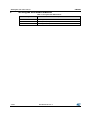
Acronyms and abbreviations
Table 1: Acronyms and abbreviations
Acronym
32/35
Description
NED
x-North, y-East, z-Down
ENU
x-East, y-North, z-Up
SEU
x-South, y-East, z-Up
DocID027533 Rev 3
UM1866
4
References
References
UM1859: Getting started with the X-CUBE-MEMS1 motion MEMS and environmental
sensor software expansion for STM32Cube.
DocID027533 Rev 3
33/35
Revision history
5
UM1866
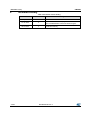
Revision history
Table 2: Document revision history
34/35
Date
Revision
Changes
15-Apr-2015
1
Initial release.
12-Jun-2015
2
Updated: Title on the cover page and osxMotionFX
plus X-CUBE-MEMS1 software architecture figure.
06-Oct-2015
3
Updated: Section 1.5.1 6-axis and 9-axis sensor fusion
osxMotionFX library.
DocID027533 Rev 3
UM1866
IMPORTANT NOTICE – PLEASE READ CAREFULLY
STMicroelectronics NV and its subsidiaries (“ST”) reserve the right to make changes, corrections, enhancements, modifications, and
improvements to ST products and/or to this document at any time without notice. Purchasers should obtain the latest relevant information on ST
products before placing orders. ST products are sold pursuant to ST’s terms and conditions of sale in place at the time of order
acknowledgement.
Purchasers are solely responsible for the choice, selection, and use of ST products and ST assumes no liability for application assistance or the
design of Purchasers’ products.
No license, express or implied, to any intellectual property right is granted by ST herein.
Resale of ST products with provisions different from the information set forth herein shall void any warranty granted by ST for such product.
ST and the ST logo are trademarks of ST. All other product or service names are the property of their respective owners.
Information in this document supersedes and replaces information previously supplied in any prior versions of this document.
© 2015 STMicroelectronics – All rights reserved
DocID027533 Rev 3
35/35