1
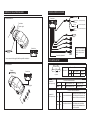
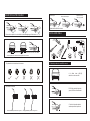
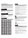
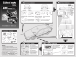
A
VRS-CONBOX-FRONT
PARKING AID SOLUTION
USER MANUAL
GENERAL INSTALLATION DIAGRAM
GENERAL WIRING DIAGRAM
Front installation *
B
D
Foot brake
Speed signal
Yellow wire
(Front system only)
Foot brake 12v+
White wire
(Front system only)
Ground
Black wire
Speed signal
On/off
switch
so
r
A
C
Control box
(Front and rear system)
Power
12v+ (Front and rear system)
Red wire
Se
n
Display
Control box
Any excess cable must be
neatly coiled and hidden
behind vehicles interior
panels.
Display
Sensitivity adjustable
* sensor extension leads supplied will be required for installation
DIP SWITCH SETUP
Rear installation
Control box
Display
Function: Front or rear selection
Dip switch1
Control box
1 2 3
Dip Switch
Dip switch 2
(Front system only)
Rear system
0.3-1.5m
Down off
Front system
0.3-1.0m
Function: Distance selection
Up
on
start to detect at 1.5m
Yellow LED light
Down
off
start to detect at 0.5m
Red LED light
D
Reversing light
on
Up
C
Function: Anti-hook selection
A
B
D
Dip switch 3
(Front system only)
Up
off
Se
n
B
so
r
C
A
Down
on
The system will operate as normal
turn anti-hook function and the display will show the real
off
distance to the rear of the vehicle.
The system will allow for a tow bar
turn anti-hook function and the display will show 20cm
less than the real distance to the
on
rear of the vehcile.
DISPLAY STATUS
DISPLAY SETUP
Press once to mute audio, press again to resume sound.
Front of display
A
Front installation
Dashboard or roof installation: Press the button for
6 seconds until the triangle changes to A (dashboard)
or B (roof) installation.
B
Safety Area
Speed setting: Press the button for 9 seconds until the 2
triangles light up and release the button. Drive slowly to the
desired speed and press the button again to set the speed sense.
* For more information please refer to installation and test section.
70-100cm
Bi……Bi……
Alarm Area
40-60cm
Reset: Press the button for 12 seconds until the 2
triangles and all the LED lights turn on and release
the button. Press once again to reset the display.
Bi…Bi…
Danger Area
0-30cm
Rear of display
Bi……
Danger Area
Buzzer
(Sound)
Function
button
0-30cm
Display
cable
Bi……
DETECTING RANGE
Rear installation
Front installation
Safety Area
Side View
110-150cm
Bi……Bi……
Alarm Area
0
0
70
70
40-100cm
100(cm)
Bi…Bi…
100(cm)
Rear installation
Side View
Danger Area
0-30cm
Bi……
Danger Area
0
90
150(cm)
0
90
150(cm)
0-30cm
Bi……
SENSOR INSTALLATION DIAGRAM
Smooth slope
90
90
90
Smooth round objects
Objects absorbing
wave, e.g. shrubs
Objects that are difficult to detect
INSTALLATION TOOLS
0.5-0.8m
Be sure that no parts of the vehicle fall into the detecting range of the sensors
0.3-0.4m
0.6-0.8m
The best position for 2-sensors The best position for 4-sensors
1. Advised position to install the sensors
up
Pay attention to the direction of the sensor
up
up
up
up
A
The direction of sensors
B
C
D
A. 4 drilled holes (A,B,C,D)
should be on the same line.
B. 0.5-0.8m vertically high to the
ground, 0.55m is recommended.
C. Vertical, tidy surface without
metal components is preferred.
Vertical installation position to the ground
Sloping installation position to the ground
5. Sensor Installation
2. Select drilling position for sensor A & D
A. Insert the sensors
into the holes with the
correct orientation
A. Choose suitable drilling position
for A & D sensor with relevant
mark.
up
D
up
B. Hide the
cables in a good
order according
to the particular
vehicles requirements.
Sensor
B. To perform the best detecting
angle, select the position for A
& D sensor ideally 8-13cm away from
the side, 11cm is recommended.
A
6. Others
3. Select drilling position for sensor B & C
If the display is installed on the roof,
please choose
A
D
B
A
If the display is installed on the dashboard,
please choose
A. Measure the distance between
sensor A and D, get the result "L".
locate the
control box
inside the
vehicle in
a cool, dry
invironment.
B. Mark sensor B & C for every 1/3
"L" interval.
7. Sensor Detecting
4. Drilling
1.5m
A. Firstly, use a small drill
bit to locate.
B. Drill with the supplied hole
cutter.
1.0m
AVRS-CONBOX-FRONT
INSTALLATION
AVRS-CONBOX-FRONT consists of a digital MCU and display which can be used with any
of the Veba colour coded sensors. The system detects the distance between a vehicle and
obstructions using the ultrasonic sensors installed in the front (or rear) bumper. The distance
will be displayed on an LED display with built in buzzer which will allow both audible and visual
notification of obstructions. This aid will allow the driver to judge the distance and avoid collisions.
MAIN FEATURES
Digital LED display
Dashboard/front roof installation
Direction indicator of left, middle and right
Front or rear installation
Antihook feature for use with tow bars and
external spare wheels
Speed sensing or footbrake (Front use only)
TECHNICAL SPECIFICATION
Ultrasonic Frequency: 40KHz
Rated Voltage: DC 12V
Working Temperature: -30~+70°C
Operating Range: DC 9~16V
Display
Size: 148*20*17mm
Operating Current: 20~200mA
Detecting Distance: 0.3~1.5m (Rear) 0.3~1.0m (Front)
ALARM MODE
Rear installation
Stage
Distance
>1. 5m
Awareness
Safety Area
Alarm Sound
1
Silence
N/A
2
3
1. 4- 1. 2m
1. 1- 0. 9m
Safety Area
Safety Area
Bi……Bi……
Bi……Bi……
1 Yellow
2 Yellow
4
0. 8m
Alarm Area
Bi…Bi…
3 Yellow
5
6
0. 7- 0. 6m
0. 5- 0. 4m
Alarm Area
Danger Area
Bi…Bi…
Bi……
4 Yellow, 1 Red
7
< 0. 3m
Danger Area
Bi……
4 Yellow, 2 Red
Alarm colour
4 Yellow
Front installation
Stage
Distance
Awareness
Alarm Sound
Alarm colour
1
>1. 0m
Safety Area
Silence
2
0.9-0. 8m
Safety Area
Bi……Bi……
N/A
1 Yellow
3
0. 7m
Safety Area
Bi……Bi……
2 Yellow
4
0. 6m
Alarm Area
Bi…Bi…
5
0. 5m
Alarm Area
Bi…Bi…
3 Yellow
4 Yellow
6
0. 4m
Danger Area
Bi……
4 Yellow, 1 Red
7
< 0. 3m
Danger Area
Bi……
4 Yellow, 2 Red
1. Once the sensors have been installed, complete the wiring and coil any excess cables.
2. Find a suitable location to mount the MCU unit. Please find a cool, dry environment for installation.
3. Connect the red (power) wire to 12v ignition of the vehicle (if using as a rear system connect this wire to the
12v positive feed from the reverse light.
4. Connect the black (ground) wire to the chassis of the vehicle ensuring a good connection is made.
5. Connect the yellow (speed pulse) wire to the speed pulse signal from the vehcile (Front installation only).
6. If the speed sene is not available in the vehicle connect the white (footbrake) wire to 12v positive signal from
the foot brake (Front installation only).
7. Find a suitable location for the display. Fix the display firmly into place and run the cable to the control
module.
8. After initial installation it may be neccassary to reset the display. This is done by pressing the reset button
at the top of the display and releasing.
9. Setup the system as mentioned in the DIP SWITCH and DISPLAY SETUP section according
to the particular installation requirements.
10. Once installation is complete, start the vehicle and begin a test drive to ensure that the system has been
set up correctly and speed sense (if used) initiates when required.
TEST
Front installation
Speed pulse: Start the vehicle and drive slowly towards a solid object i.e. a brick wall. the
sensors will begin to activate when vehicle speed is below the set speed and obstruction
is between 1m and 0.5m (depending on setup).
Foot brake: Start the vehicle and drive slowly towards a solid object i.e. brick wall. The
sensors will begin to activate when the vehicles foot brake is pressed. if an obstruction is
present the sensors will stay on, if there is no obstruction the sensors will turn off after 15
seconds of operation.
Rear installation
Place a board (100cm x 20cm) within 1.5m in front of the sensors. The system should start the warning
procedure and sound indication of distance.
NOTE
1. When installing the system, the vehicles engine should be off.
2. The performance of the sensors may be affected by the following situations: Heavy rain, loose
gravel roads, bumpy / uneven roads, extreme heat or cold conditions, moist weather and if the
sensors are covered in snow, ice or mud.
3. Other ultrasonic or electronic waves may affect the performance of the system.
4. The sensors should not be installed too tight or too loose (Please use the supplied drill bit).
5. The performance of the sensors may be affected if the sensors are fitted into. metal bumpers.
6. Do not install the control unit or sensors close to other interference sources such as exhaust
pipes or vehicles wiring.
7. Test the system to make sure it operates correctly before using.
8. This parking system acts only as an aid, in the case of any accident the manufacturer or
distributor is not responsible.