1
USER MANUAL
Stirrer Speed Controller AD11032
For Motor P100-310, Version 4, January 2000
USER MANUAL
STIRRER SPEED
CONTROLLER ADI 1032
FOR MOTOR P100-310
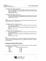
The Stirrer Motor
The Stirrer Speed Controller
appikorf
DEPENDABLE INSTRUMENTS
V1UBCE5014
USER MANUAL
SYMBOLS
Stirrer Speed Controller AD11032
For Motor P100-310, Version 4, January 2000
SYMBOLS
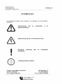
The following symbols are used on equipment and in the documentation:
Caution; refer to this user manual.
Caution; electrical shock hazard.
I
Important note; read the instructions carefully.
Power switch (on/off)
Applikon Dependable Instruments
3125 AE Schiedam
Tel.: (31 )(0)10-4621855
appiikort
DEPENDABLE INSTRUMENTS
De Brauwweg 13
The Netherlands
Fax.:(31)(0)10-4379648
USER MANUAL
Stirrer Speed Controller AD11032
For Motor P100-310, Version 4, January 2000
SAFETY CLASS I APPARATUS
This apparatus has been designed in accordance with
IEC1010-1 "Safety Requirements for Electrical Equipment
for Measurement, Control and Laboratory Use", and has
been supplied in a safe condition. The user manual
contains information and warnings which have to be
followed by the user to ensure safe operation and to retain
the apparatus in safe condition.
Before switching the apparatus on, make sure that it is set
to the line voltage.
This apparatus is designed for stirrer speed control in
bioprocesses; it must not be used for other purposes!
Caution:
Any interruption of the protective conductor inside or
outside the apparatus will make the apparatus dangerous.
Intentional interruption is prohibited.
Any adjustment, maintenance and repair of the opened
apparatus under voltage shall be avoided as far as
possible and, if inevitable, must only be carried out by
qualified personnel.
Make sure that only fuses with the required rated current
and of the specified type (IEC 127) are used for
replacement. The use of makeshift fuses and the shortcircuiting of fuse holders is prohibited.
appikorf
DEPENDABLE INSTRUMENTS
CE CONFORMITY
EU DECLARATION OF CONFORMITY
The company Applikon Dependable Instruments B.V.,
Schiedam, The Netherlands, hereby certifies that the
instrument:
ADI 1032/1 STIRRER SPEED CONTROLLER
meets the requirements of the EU Directives 89/336/EEC
(Electromagnetic Compatibility) and 73/23/EEC (Low
Voltage).
SOURCE OF THE SPECIFICATIONS:
89/336/EEC:
73/23/EEC
EN 50081-1 (1992) EMC Generic emission standard.
Residential, commercial and light industry.
EN 50081-2 (1993) EMC Generic emission standard. Industrial
environment.
EN 50082-1 (1992) EMC Generic immunity standard.
Residential, commercial and light industry.
EN 50082-2 (1995) EMC Generic immunity standard. Industrial
environment (including table A.4.1, A.4.2 A.4.3 and A.4.5).
EN 61000-3-2 (1995) EMC Limits for harmonic current
emissions (equipment input current < 16A per phase).
EN 61000-3-3 (1995) EMC Limits concerning voltage
fluctuations and flicker for equipment having an input current up
to and including 16 A per phase.
EN 61010 Safety requirements for electrical equipment for
measurement, control and laboratory use.
ing J. van Burg, President.
Applikon Dependable Instruments
3125 AE Schiedam
Tel.: (31 )(0)10-2983555
appiikorf
DEPENDABLE INSTRUMENTS
14.10.96
De Brauwweg 13
The Netherlands
Fax.: (31 )(0)10-4379648
USER MANUAL
Stirrer Speed Controller AD11032
CONTENTS
For Motor P100-310, Version 4, January 2000
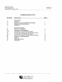
TABLE OF CONTENTS
Chapter
Description
Page
1
1.1
1.2
1.3
1.4
THE STIRRER MOTOR
General
Description of the different motor types
Standard stirrer speed ranges
Maintenance
1
1
2
3
2
2.1
2.1.1
2.1.2
2.2
2.2.1
2.3
2.4
2.5
2.6
2.7
THE STIRRER SPEED CONTROLLER
ADI 1032 stand alone controller
Fuses, voltage selection and supply
I/O connections and remote control
The ADI 1032 module in an ADI 1035 Bio Console
I/O connections and remote control
The ADI 1032 module in an ADI 1075 Pilot System
Remote control signal
Installation
Environmental conditions
Drawings
4
6
7
8
9
10
12
12
13
13
applikor?
DEPENDABLE INSTRUMENTS
USER MANUAL
Stirrer Speed Controller AD11032
THE STIRRER MOTOR
For Motor P100-310, Version 4, January 2000
CHAPTER 1
THE STIRRER MOTOR
1.1 GENERAL:
This chapter describes five different DC permanent magnet motors for ADI bioreactors.
A direct current tacho generator, present in the motor, is used for feedback to the motor
controller; this feedback signal (speed) is also present as an analog output (0 - 10 V) on the
controller.
The stirrer motor comes with four motor studs to fit in the stirrer assembly and a covered
(flexible) coupling fork to avoid noise and vibrations during operation.
No tools are required to mount the stirrer motor on top of the stirrer assembly.
Warning:
- The stirrer motor is a machine with potential hazard (moving
parts).
In order to avoid dangerous situations, make sure that the
stirrer motor is only operated when it is properly seated in
the stirrer assembly of the ADI autoclavable bioreactor.
- The stirrer motor must only be used as part of a Bio Process
(bioreactor with control systems); it therefore comes with
suppliers declaration of conformity of type lib regarding the
European Community legislation on machinery! The stirrer
motor must not be put into service until the machinery into
which it is to be incorporated has been declared to be
conform machinery directive 89/392/EEG and 91/368/EEG.
1.2 DESCRIPTION OF THE DIFFERENT MOTOR TYPES:
Z5100002M0: Stirrer Motor Assembly P100
Motor PI00 including motor studs and flexible coupling; Standard motor for the ADI
1-3 liter bioreactors with low viscous media and a stirrer speed range of 0 -1250 rpm.
The motor can also be used with the 1-7 liter cell culture applications with a stirrer
speed range of 0 - 500 rpm.
Maximum torque: 0.20 Nm.
appikorf
DEPENDABLE INSTRUMENTS
USER MANUAL
Stirrer Speed Controller AD11032
THE STIRRER MOTOR
For Motor P100-310, Version 4, January 2000
Z5100002M1: Stirrer Motor Assembly PI40
Motor PI40 including motor studs and flexible coupling; heavy duty motor for the
ADI 1-3 liter bioreactors, used in tough applications with viscous media and stirrer
speeds up to 2000 rpm.
Maximum torque: 0.30 Nm.
Z5100002M3: Stirrer Motor Assembly P310
Motor P310 including motor studs and flexible coupling; standard motor for the ADI
7 liter bioreactor, to be used in normal applications with stirrer speeds up to 1000 rpm.
Maximum torque: 0.55 Nm.
Note:
All three stirrer motors described above, fit in both the magnetically coupled and lipseal stirrer
assemblies of the ADI 1-7 liter bioreactors.
Z510000001: Stirrer Motor Assembly P100 i=6
Motor PI00, i=6, including motor studs and coupling; (stirrer speed is reduced 6.25
times by a planetary gear box).
Standard motor for cell culture bioreactors and a standard stirrer speed range of 0 - 200
rpm.
Maximum torque: 1.0 Nm.
Z510000002: Stirrer Motor Assembly PI40 i=2
Motor PI40, i=2, including motor studs and coupling; (stirrer speed is reduced 2 times
by a planetary gear box).
Heavy duty motor for cell culture bioreactors and a standard stirrer speed range of 0 500 rpm.
Maximum torque: 0.48 Nm.
Note:
Stirrer motors with planetary gear box fit in both the magnetically coupled and lipseal stirrer
assembly of the ADI 15 liter and larger bioreactors. Application of these motors is limited by
the required torque.
1.3 STANDARD STIRRER SPEED RANGES:
The stirrer motors, in combination with the stirrer speed controller, are calibrated to standard
stirrer speed ranges as listed below:
Motor type
Default stirrer speed range (rpm)
P100
0-1250
P140
0 - 2000
P310
0-1000
P100, i=6
0-200
P140, i=2
0 - 500
appiikorf
DEPENDABLE INSTRUMENTS
USER MANUAL
Stirrer Speed Controller ADI1032
THESTIRRERM OTO R
For Motor P100-310, Version 4, January 2000
If specified otherwise in the purchase order, other ranges can be calibrated. Use order nbr.
Z510120000: specific calibration range of motor and motor controller (specify the required
range when ordering).
I
Note:
The combination of a stirrer motor and a motor controller is calibrated; for
accurate reproducibility of the stirrer speed, this combination must be kept
together.
1.4 MAINTENANCE:
The stirrer motor is virtually maintenance free. The only parts that require regular maintenance
are the carbon brushes and the ball bearings. The life span of the carbon brushes depends on
the operating conditions (normally approx. 6000 operating hours). Minimum length of the
carbon brush: - Carbon brush for motor: 9 mm,
- Carbon brush for tacho: 6 mm.
Operating the stirrer motor with worn-out carbon brushes will cause irreversible damage!
The stirrer motor should be serviced every 12,000 - 15,000 operating hours; revision
instructions and spare parts are listed in the corresponding maintenance data sheets (MDS).
appiikorf
DEPENDABLE INSTRUMENTS
USER MANUAL
Stirrer Speed Controller ADM032
STIRRER SPEED CONTROLLER
For Motor P100-310, Version 4, January 2000
CHAPTER 2
STIRRER SPEED CONTROLLER
GENERAL:
ADI provides a stirrer speed controller in two versions for different applications. In this
chapter, these stirrer speed controller options are described. The stirrer speed controller can
be used in combination with the PI00, PI40 and P310 motor types.
Article number
Description
Z510320010
Stand alone stirrer speed controller P100/P140/P310
Z510320030
Stirrer speed control module P100/P140/P310 to be installed in the:
-ADI 1035 Bio Console
- ADI 1075 Bio Pilot System
The ADI 1032 stand alone stirrer speed controller can be used as an individual stirrer speed
controller or in combination with a controller like the ADI 1030 Bio Controller.
The ADI 1035 Bio Console is an actuator console for autoclavable bioreactors, containing
hardware components such as a stirrer speed controller, rotameter assemblies or mass flow
controllers, pumps, etc (refer to the user manual of this device). This Bio Console can be used
in combination with the ADI 1030 Bio Controller.
The ADI 1075 Pilot System is an actuator console for In Situ Sterilizable systems, containing
hardware components such as a stirrer speed controller, rotameter assemblies, pumps,
temperature and sterilization control (refer to the user manual of this system). This actuator
console is used in combination with controllers like the ADI 1040 or ADI 1060 Control
Console and / or host systems.
appikon"
DEPENDABLE INSTRUMENTS
USER MANUAL
STIRRER SPEED CONTROLLER
Stirrer Speed Controller AD11032
For Motor P100-310, Version 4, January 2000
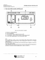
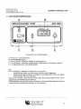
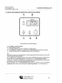
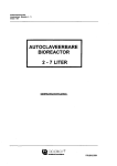
2.1 ADI 1032 STAND ALONE CONTROLLER:
A
B
ABE 1&31
Fid
PO» :R ON
STIRRER SPEED
OVERLOAD
SPEED
LOCAL
REl 07E
J
V
D
Front view of the Stirrer Controller
A = Power-on / overload indicator,
B = Stirrer speed display,
C = Power "On/Off switch, switches the power on/off,
D = "Local/Remote" switch, switches between local and remote control,
E = 10 turn control potentiometer for local stirrer speed control.
Note:
The "Local/Remote" switch is used to select manual stirrer speed control by using the
potentiometer on the front panel ("local") or by an analog (0/4 - 20 mA or 0 - 10 V) input
signal ("remote").
In overload situations (green LED turns red), the maximum torque is supplied; as a result, the
stirrer speed will be reduced.
After changing the stirrer speed set point (local or remote), the stirrer speed will ramp up/down
until the new set point is reached (ramping speed = approx. 60 rpm/sec).
appiikon*
DEPENDABLE INSTRUMENTS
USER MANUAL
STIRRER SPEED CONTROLLER
Stirrer Speed Controller AD11032
For Motor P100-310, Version 4, January 2000
A
I/O! I G N A I S
REMOTE CONTROL
o((v
IT 0 8 Al
©
Z5103Z0010
M60VA
©
~| Kt».
| - r a - IT 0.8A/T 1 6
J
V
MOTOR CABLE
©
V
LJUJ
C
D
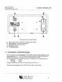
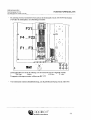
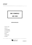
Rear view of the Stirrer Controller
A = 9 Pins female "sub-D" connector for remote I/O control,
B = Fuse holder and voltage selection,
C = Cable connector for stirrer motor,
D = General identification sticker,
E = Main supply entry.
2.1.1 FUSES. VOLTAGE SELECTION AND SUPPLY:
When the fuse holder (B) is removed (use a little screwdriver), a voltage selector (115/ 230
V) becomes visible. Make sure that the selector is correctly inserted (sticker with the correct
line voltage must be in view); if not, take out the voltage selector, rotate it 180° and re-insert
it.
The fuse holder contains two fuses for both the live and neutral side; fuse rating:
230 Vac:
T 0.8A,
115 Vac:
T 1.6A.
Applied fuses must comply with IEC 127!
Use the main supply cable to connect the ADI 1032 to the mains (Euro connector in the ADI
1032, mains connector in the wall socket).
appiikorf
DEPENDABLE INSTRUMENTS
USER MANUAL
Stirrer Speed Controller ADI1032
STIRRER SPEED CONTROLLER
For Motor P100-310, Version 4, January 2000
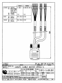
2.1.2 I/O CONNECTIONS AND REMOTE CONTROL:
Cable Z510120900 or cable Z510120901 (see drawing D1012-lc.06.051) is used to connect
the controller to any device that generates a stirring speed set point; this cable also offers the
possibility to stop (inhibit, active when connected to ground) the stirrer for a period of time and
to record the motor speed and torque (0 - 10 V outputs) signals.
Control cable: WH (white)
YE (yellow)
=
=
BR (brown)
GN (green)
WH (white)
BR (brown)
WH (white)
BR (brown)
=
=
=
=
=
=
Speed cable:
Torque cable:
stirrer speed set point (0/4 - 20 mA or 0 - 10 V).
input inhibited (when connected to the ground, the
controller is switched off).
ground.
+13 Vdc (for external purpose).
stirrer speed output (0 - 10 V).
ground.
torque output (0-10 V).
ground.
Note:
The stirrer speed set point range can be selected by jumpers. Refer to chapter 2.4.
In all cases, the low stirrer speed range limit (0/4 mA or 0 V) input signal is equivalent to a 0
rpm agitation. A 20 mA or 10 V input signal is equivalent to the maximum stirrer speed for
which the motor controller has been calibrated.
The "inhibit" option can be used to stop the stirrer motor without interrupting any control
algorithm (for instance in a cell culture, to allow the cells to attach to micro-carriers).
Note:
Z510120900: Contr. cable, L = 600 mm
Z510120901: Contr. cable, L = 2000 mm
After connecting the motor controller to the ADI 1030, make sure that all unused wires are
insulated. Set the right hand switch on the front panel of the motor controller to the "remote"
position (refer to the ADI 1030 user manual for programming instructions).
appikorf
DEPENDABLE INSTRUMENTS
USER MANUAL
STIRRER SPEED CONTROLLER
Stirrer Speed Controller AD11032
For Motor P100-310, Version 4, January 2000
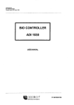
2.2 THE ADI 1032 MODULE IN AN ADI 1035 BIO CONSOLE:
A
B
CN
P0 VER
OFF
OVERLOAD
SPEED
C
STIRRER SPEED
POWER
RPM
LOCAL
REK OTE
D
E
F
G
Front view of the Stirrer Controller
A = Power "On/Off switch, switches the power on/off,
B = Power-on / overload indicator,
C = Stirrer speed display,
D = Fuse holder,
E = 10 turn control knob for local stirrer speed control,
F = "Local/Remote" switch, switches between local and remote control,
G = Cable connector for stirrer motor.
Note:
The 9 Pins female "sub-D" connector for remote I/O control is located at the rear side of the
ADI 1035.
The "Local/Remote" switch is used to select manual stirrer speed control by using the control
knob on the front panel ("local") or by a 0/4 - 20 mA (or 0 - 10 V) input signal ("remote").
In overload situations (green LED turns red), the maximum torque is supplied; as a result, the
stirrer speed will be reduced.
After changing the stirrer speed set point (local or remote), the stirrer speed will ramp up/down
until the new set point is reached (ramping speed = approx. 60 rpm/sec).
The fuse holder contains a fuse with the following rating:
230 Vac:
T 0.8A,
115 Vac:
T 1.6A.
Applied fuses must comply with IEC 127!
appiikorf
DEPENDABLE INSTRUMENTS
8
USER MANUAL
STIRRER SPEED CONTROLLER
Stirrer Speed Controller AD11032
For Motor P100-310, Version 4, January 2000
2.2.1 I/O CONNECTIONS AND REMOTE CONTROL:
Cable Z510120900 or cable Z510120901 (see drawing D1012-lc.06.051) is used to connect
the controller to any device that generates a stirring speed set point (9 pins "sub-D" connector
is located at the rear of the ADI 1035); this cable also offers the possibility to stop (inhibit,
active when connected to ground) the stirrer for a period of time and to record the motor speed
and torque (0 - 10 V outputs) signals.
Control cable: WH (white)
YE (yellow)
stirrer speed set point (0/4 - 20 mA or 0 - 10 V).
input inhibited (when connected to the ground, the
controller is switched off).
ground.
+13 Vdc (for external purpose).
stirrer speed output ( 0 - 1 0 V).
ground.
torque output (0 - 10 V).
ground.
BR (brown)
GN (green)
Speed cable: WH (white)
BR (brown)
Torque cable: WH (white)
BR (brown)
Note:
The stirrer speed set point range can be selected by jumpers. Refer to chapter 2.4.
hi all cases, the low stirrer speed range limit (0/4 mA or 0 V) input signal is equivalent to a 0
rpm agitation. A 20 mA or 10 V input signal is equivalent to the maximum stirrer speed for
which the motor controller has been calibrated.
The "inhibit" option can be used to stop the stirrer motor without interrupting any control
algorithm (for instance in a cell culture, to allow the cells to attach to micro-carriers).
Note:
Z510120900: Contr. cable, L = 600 mm
Z510120901: Contr. cable, L = 2000 mm
After connecting the stirrer speed controller to a controller like the ADI 1030, make sure that
all unused wires are insulated. Set the right hand switch on the front panel of the motor
controller to the "remote" position (for programming instructions, refer to the user manual of
the controller).
applikorf
DEPENDABLE INSTRUMENTS
USER MANUAL
Stirrer Speed Controller AD11032
For Motor P100-310, Version 4, January 2000
STIRRER SPEED CONTROLLER
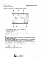
2.3 THE ADI 1032 MODULE IN AN ADI 1075 PILOT SYSTEM:
Front view of the Stirrer Controller
A = Power-on / overload indicator,
B = Stirrer speed display,
C = Power "On/Off switch, switches the power on/off,
D = "Local/Remote" switch, switches between local and remote control,
E = 10 turn control knob for local stirrer speed control.
Note:
The stirrer speed set point can be controlled by a controller like the ADI 1040 Control Console
or ADI 1030 Bio Controller.
The "Local/Remote" switch is used to select manual stirrer speed control by using the control
knob on the front panel ("local") or by a 0/4 - 20 mA (or 0 - 10 V) input signal ("remote").
In overload situations (green LED turns red), the maximum torque is supplied; as a result, the
stirrer speed will be reduced.
After changing the stirrer speed set point (local or remote), the stirrer speed will ramp up/down
until the new set point is reached (ramping speed = approx. 60 rpm/sec).
appikorf
DEPENDABLE INSTRUMENTS
10
USER MANUAL
Stirrer Speed Controller AD11032
For Motor P100-310, Version 4, January 2000
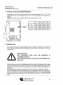
STIRRER SPEED CONTROLLER
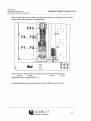
The fuse for the stirrer motor can be found at the fuse terminal row inside the ADI 1075 Pilot
System (remove the rear panel). See image below:
F4.
F1 .. F3
©
Fuse holder F23 contains the fuse for the stirrer motor with the following rating:
230 Vac:
T 0.8A,
115 Vac:
T 1.6A.
Applied fuses must comply with IEC 127!
- For information about remote control, refer to the user manual of the ADI 1075.
appiikorf
DEPENDABLE INSTRUMENTS
11
USER MANUAL
STIRRER SPEED CONTROLLER
Stirrer Speed Controller AD11032
For Motor P100-310, Version 4, January 2000
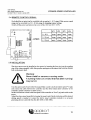
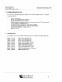
2.4 REMOTE CONTROL SIGNAL:
Per default the set point can be controlled with an analog 0 - 10 V signal. This remote control
range can be converted to a 0/4 - 20 mA range by changing jumper settings.
Switch off the power and remove the cover of the 1032 (or 1035 /1075).
O
o
0
X9
»r
•i
•I
•I
»l
•I
ROFFS
i»R6
m R4
to
R13
1» R25
to RM
1* R31
-Jumpers
JP3
JP4
JP1
JP2
JP3
JP4
0 -10 V
close
open
open
open
0 -20 mA
close
close
open
open
4 -20 mA
open
close
close
close
XT
X1.
P
X2 E Z ]
P
ee
| R5 DISPLAY
R24 Vout
|R27 SPEED
oaaapaaaaa
o
2.5 INSTALLATION:
The stirrer motor must be installed on the reactor by inserting the four pins into the coupling
ring of the stirrer assembly while lining up the spring pin on the stirrer shaft with the flexible
fork on the motor shaft.
Warning:
Never install or remove a running motor.
A running motor (or a motor that has been running)
may be hot.
Turn the speed control knob on the front panel fully counter clockwise (stirrer speed = 0 rpm)
and connect the cable between the controller and the stirrer (male audio connector to the
controller, female connector to stirrer motor).
Set the local/remote switch at the front panel of the controller to "local" (up) and switch on the
power.
Adjust the stirrer speed manually by turning the speed control knob clockwise until the desired
stirring speed is reached or connect the stirrer speed controller (module) to a set point
generating device (controller like the ADI 1030 or ADI 1040).
appikorf
DEPENDABLE INSTRUMENTS
12
USER MANUAL
STIRRER SPEED CONTROLLER
Stirrer Speed Controller AD11032
For Motor P100-310, Version 4, January 2000
2.6 ENVIRONMENTAL CONDITIONS:
The ADI 1032 Stirrer Speed Controller (module) may be used at locations with the following
environmental conditions:
Indoor use,
Altitude: up to 2000 m,
Temperature: 4°C to 40°C,
Maximum relative humidity 80% for temperatures up to 31°C, decreasing linearly to
50% relative humidity at 40°C,
Mains supply voltage: 115/230 Vac (+15%/-20%), 50/60Hz,
Transient overvoltages according to INSTALLATION CATEGORIES II,
POLLUTION DEGREE 2 in accordance with IEC 664,
P-max=160VA.
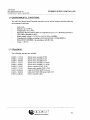
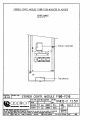
2.7 DRAWINGS:
The following drawings are included:
D3001-1 .12.010
D3001-1 .12.020
D3OO7-1 .06.006
D3015-1 .12.015
D3015-1 .06.001
D1032-2 .12.501
D1032-2 .12.521
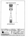
D1012-ld.06.031
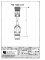
D1012-1 .06.030
D1012-lc.06.051
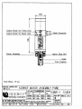
Stirrer motor assembly PI00
Stirrer motor assembly PI40
Stirrer motor assembly P310
Stirrer motor assembly i=6 P100
Stirrer motor assembly i=2 P140
Stirrer controller PI00-P310
Stirrer contr. module P100 - P310
Cable for P100/P140/P310 motor
Cable for P100-P1000 motor ADI 1035
Motor controller cable
appikorf
DEPENDABLE INSTRUMENTS
13
Carbon Brush for Tacho (2x)
Carbon Brush for Motor (2x)
Cable Connector
Stirrer Assembly
Motor Stud (4x)
Cover
Fork Coupling
Total Mass; 1.6 kg
PROJECTION
DRAWING NAME
STIRRER MOTOR ASSEMBLY P100
DRAWING
PART NBR.: Z5100002M0
D3001-1 .12.010
SCALE
NBR. :
1
toappiikorf
^
•
^
DESIGNED
DEPENDABLE INSTRUMENTS
CHECKED
07 feb. 1995
07 feb. 1995
MVo
MVo
_ 1995 Applikon Dependable Instruments B.V.
No part of this drawing may be copied or reproduced h any form or by any means or transferred
to any third party without the prior written consent of Applikon Dependable Instruments B.V.
A.D.I. B.V.
E l P - 0 . BOX 149
3100 AC SCHIEDAM
HOLLAND
©(31)10-4621855
APPR
SHEET: 1
OF 1
SIZE:
A4
DIMENSIONS
ARE IN mm
FAX (31)10-4379648
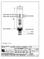
Carbon Brush for Tacho (2x)
Cable Connector
Carbon Brush for Motor (2x)
Stirrer Assembly
Motor Stud (4x)
Cover
Fork Coupling
Total Mass; 1.9 kg
PROJECTION
DRAWING NAME
STIRRER MOTOR ASSEMBLY P140
DRAWING
PART NBR.: Z5100002M1
D3001-1 .12.020
NBR. :
SCALE
1
toappiikorf
DESIGNED
^ ^ 1 ^ ^ DEPENDABLE INSTRUMENTS
CHECKED
07 Feb. 1995
07 Feb. 1995
MVo
MVo
© 1995 Applikon Dependable Instruments B.V.
No part of this drawing may be copied or reproduced in any form or by any means or transferred
to any third party without the prior written consent of Applikon Dependable Instruments B.V.
A.D1 B.V.
. BOX 149
3100 AC SCHIEDAM
HOLLAND
<g? (31)10-4621855
APP
SHEET: 1
OF
DIMENSIONS
ARE IN mm
FAX (31)10-4379648
SIZE:
A4
082.5
A
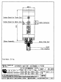
Carbon Brush for Tacho (2x)
Carbon Brush for Motor (2x)
Cable Connector
Stirrer Assembly
Motor Stud (4x)
Cover
Fork Coupling
Total Mass; 3.9 kg
PROJECTION
:
DRAWING NAME :
STIRRER MOTOR ASSEMBLY P310
Z5100002M3
D3007-1 .06.006
1
lOappikorf
PART NBR.
DRAWING
SCALE
NBR. :
DESIGNED
^ ^ J ^ D E P E N D A B L E INSTRUMENTS
CHECKED
07 feb. 1995
07 feb. 1995
MVo
MVo
© 1995 Applikon Dependable Instruments B.V.
No part of this drawing may be copied or reproduced in any form or by any means or transferred
to any third party without the prior written consent of Applikon Dependable Instruments B.V.
A.D.I. B.V.
E3P.0. BOX 149
3100 AC SCHIEDAM
HOLLAND
©(31)10-4621855
APPR.:
SHEET: 1
OF
iKI
DIMENSIONS
ARE IN m m
FAX (31)10-4379648
SIZE:
A4
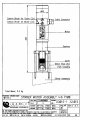
Carbon Brush for Tacho (2x)
Cable Connector
Carbon Brush for Motor (2x)
Motor
Gearbox
Cover
Motor Stud (4x)
Fork Coupling
Stirrer Assembly
Total Mass; 2.4 kg
PROJECTION
DRAWING NAME
:
STIRRER MOTOR ASSEMBLY i = 6 P100
DRAWING
PART NBR.: Z510000001
D3015-1 .12.015
SCALE
NBR. :
1
toapplikorf
^
•
^
DESIGNED
DEPENDABLE INSTRUMENTS
CHECKED
07 Feb. 1995
07 Feb. 1995
MVo
MVo
© 1995 ApplDcon Dependable Instruments B.V.
No part of this drawing may be copied or reproduced in any form or by any means or transferred
to any third party without the prior written consent of Appiikon Dependable Instruments B.V.
A.D.I. B.V.
IE3P.O. BOX 149
3108 AC SCHIEDAM
HOLLAND
@ (31)10-4621855
APP
SHEET: 1
OF 1
SIZE:
A4
DIMENSIONS
ARE IN mm
FAX (31)10-4379648
Carbon Brush for Tacho (2x)
Cable Connector
Carbon Brush for Motor (2x)
ao
Protection Tube
Motor Stud (4x)
Fork Coupling
Stirrer Assembly
Total Mass; 2.7 kg
PROJECTION
DRAWING NAME
STIRRER MOTOR ASSEMBLY i = 2 P140
DRAWING
PART NBR.: Z510000002
D3015-1 .06.001
SCALE
NBR. :
1
toapplkort
DESIGNED
^ ^ l ^ ^ DEPENDABLE INSTRUMENTS
CHECKED
07 feb. 1995
07 feb. 1995
MVo
MVo
API
© 1997 Applfcon Dependable Instruments B.V.
No part of this drawing may be copied or reproduced in any form or by any means or transferred
to any third party without (he prior written consent of Appltkon Dependable Instruments B.V.
A.D.I. B.V. E3P-O. BOX 149
3100 AC SCHIEDAM
HOLLAND
@ (31)10-4621855
SHEET: 1
OF
DIMENSIONS
ARE IN mm
FAX (31)10-4379648 SIZE :
A4
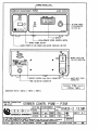
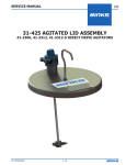
STIRRER MOTOR TYPE
Stifismr
PM
AB
SflRRER SPEED
RPM
HSU
SPEED
o
REMOTE
10 TURN SPEED
POTENTIOMETER
0-1250 rpm
LC-DISPLAY
LOCAL/REMOTE SPEED CONTROL SWITCH
MAINS POWER ON/OFF
MAINS POWER ON LED GREEN AND MOTOR OVERLOAD LED RED
MAINS FUSES AND
VOLTAGE SELECTION
HA1AI
UOTOR CABLE
9
L
REMOTE CONTROL 9pin SUB-D CONNECTOR
P100-310 MOTOR CONNECTOR
MAINS INPUT EURO
CONNECTOR
Default P100 motor
230Vac 50Hz
DIMENSIONS WxHxD: 260mm x 130mm x 450mm
PROJECTION
DRAWING NAME :
STIRRER CONTR. P100 - P310
PART NBR.: Z510320010
NG
r
D1032-2 .12.501
SCALE
1
Igappiikon
^
•
^
DESIGNED :
DEPENDABLE INSTRUMENTS
CHECKED
17 jan. 2000
17 jan. 2000
RKo
HMa
© 1999 Applikon Dependable Instruments B.V.
No part of this drawng may be copied or reproduced in any form or by any means or transferred
to any third party without the prior written consent of Applikon Dependable Instruments B.V.
A.D.I. B.V.
E l P.O. BOX 149
3100 AC SCHIEDAM
HOLLAND
© (31)10-2983555
SHEET:
OF
SIZE :
A4
DIMENSIONS
ARE IN mm
FAX (31)10-4379648
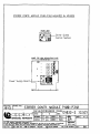
STIRRER CONTR. MODULE P100-P310 MOUNTED IN ADI1035
FRONT VIEW
(MOTOR CCNTROiER StCnON)
CZD
Stirrer Speed
Control Section
INNER TOP VIEW SEPARATION PLATE
(VIEW fJCII 5IGHT SCE)
Power Supply Board
PROJECTION
DRAWING NAME
STIRRER CONTR. MODULE P100-P310
DRAWING
PART NBR.: Z510320030
NBR. : D1032-2 .12.521
SCALE
1
toappikori
^
^
^
DESIGNED
DEPENDABLE WSTOUMENTS
CHECKED
17 jan. 2000
17 jan. 2000
RKo
HMa
© 1999 Applkon Dependable Instruments B.V.
No port of this drawng may be copied or reproduced in any form or by any means or transferred
to any third party without the prior written consent of Applikon Dependable Instruments B.V.
A.D.I. B.V.
-O. BOX 149
31W AC SCHIEDAM
HOLLAND
©(31)1^-2983555
SHEET: 1
OF 5
SIZE :
A4
DIMENSIONS
ARE IN mm
FAX (31)10-4379648
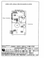
STIRRER CONTR. MODULE P100-P310 MOUNTED IN AD11035
INNER VIEW REAR PLATE
Stirrer Controller
Transformer
PROJECTION
DRAWING NAME :
STIRRER CONTR. MODULE P100-P310
PART NBR.: Z510320030
DRAWING
SCAL£
NBR. : D1032-2 .12.521
1
tOappiikon
^
^
^
DESIGNED
DEPENDABLE INSTRUMENTS
CHECKED
17 jon. 2000
17 jon. 2000
RKo
HMa
1999 Appljkon Dependable Instruments B.V.
port of the drawing may be copied or reproduced in any form or by any means or transferred
to any third party without the prior written consent of Applkon Dependable Instruments B.V.
A.D.I. B.V.
E3f\C\ BOX 149
3100 AC SCHIEDAM
HOLLAND
©(31)10-2983555
SHEET: 2
DIMENSIONS
ARE IN mm
FAX (31)10-4379648
SIZE
A4
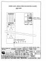
STIRRER CONTR. MODULE P100-P310 MOUNTED IN AD11075
ADH075 CABINET
FRONT VIEW
Q,u
i!
j:
>
-.
•
-
• i
1
•
•
t
i
^
i
1
1 1
1
-
—
—
•
•
i
i
i i
i •
•
•
i •
i
i
1
1
(
i
i
i •
t
i t
i
i <
J •
i
1
1
r
'—*>
1
•
1 IF5HI .
iiii %
%
i
: i
! i
i
_Stirrer Speed
Control Section
j
*
LJ
i
\
/v
Pilot System
>
ADI1075
~-\
t~.
ACID
o
'•*'
;
-is
•_.
a J O
•SI 1
GLAND FOR STIRRER MOTOR CABLE
PROJECTION
DRAWING NAME :
STIRRER CONTR. MODULE P100-P310
DRAWING
PART NBR.: Z510320030
NBR. : D1032-2 .12.521
SCALE
1
IQappiikorf
^
^
^
DE3GNED
DEPENDABLE MS1RUMENTS
CHECKED
17 jan. 2000
17 jan. 2000
RKo
HMa
© 1999 Applkon Dependable Instruments 8.V.
No port of this drawng may be copied or reproduced in any form or by any means or transferred
to any third party without the prior written consent of Applikon Dependable Instruments B.V.
A.D.I. B.V.
G3P.O. BOX H9
3100 AC SCHIEDAM
HOLLAND
@(31)10-2983555
SWEET: 3
OF 5
SIZE :
A4
DIMENSIONS
ARE IN mm
FAX (31)10-4379648
STIRRER CONTR. MODULE P100-P310 MOUNTED IN ADI1075
ADH075 CABINET
REAR VIEW /fllWCUT COVE!)
Stirrer Controller
Fuse (F23)
Power Supply Board
Voltage Selection
Rail (X10)
@ff Transformer (T21)
PROJECTION
DRAWING NAME :
STIRRER CONTR. MODULE P100-P310
PART NBR.: Z510320030
DRAWING
SCALE
NBR. : D1032-2 .12.521
1
toappiikorf
^
^
^
DESGNED :
DEPENDABLE NSTRUIIENTS
CHECKED
17 jan. 2000
17 jan. 2000
RKo
HMa
© 2000 Applikon Dependable Instruments B.V.
No part of this drawing may be copied or reproduced in any form or by any means or transferred
to ony third party without the prior written consent of Applikon Dependable Instruments B.V.
A.D.I. B.V.
EJP.O. BOX 149
3100 AC SCHIEDAM
HOLLAND
©(31)10-2983555
SHEET: 4
Cf
SIZE :
A4
DIMENSONS
ARE IN mm
FAX (31)10-4379648
5
STIRRER CONTR. MODULE P100-P310 MOUNTED IN AD11075
ADM 075 CABINET
INNER VEW SIGHT SIDE
Stirrer Controller
1
II
i
t '-' il_
! @
1
i
t ""' !
® !
Transformer
PRO<ECT1ON
DRAWING NAME
STIRRER CONTR. MODULE P100-P310
PART NBR.: Z510320030
™D1032-2 .12.521
SCALE
1
toappiiKorr
DESIGNED
^ ^ ^ D E P E M ) A B L £ MSTRUMENTS
CHECKED
17 jqn. 2000
17 jan. 2000
RKo
HMa
1999 Applkon Dependable Instruments B.V.
> port of this drawrg may be copied or reproduced in any form or by any means or transferred
to any third party without the prior written consent of ApplBton Dependable Instruments B.V.
A.D.I. B.V.
G3P-0- BOX U 9
3100 AC SCHIEDAM
HOLLAND
©(31)10-2983555
SHEET: 5
OF 5
SIZE :
A4
DIMENSIONS
ARE IN mm
FAX (31)19-4379648
P100/P140/P310 MOTOR
2500
n
f 1
0
TZJ
MDTORCONTROLLER
POS.
QTY.
DESCRIPTION
i
MATERIAL OR TYPE
REMARKS
CHECKED:
CABLE FOR P100/P140/ '310 MOTOR
1
applikon
PART NO.
DESIGN.
DEPENDABLE INSTRUMENTS
Z5101J21C01
SCALE
DATE
MOD.
L.H.
07- 03-1986
090293
DRAWING NO.:
D1012-1d.06.031
SHEET
1
OF
1
DIMENSIONS IN mm | FORM: A 4
O Iflgs Applikon Dependable Instruments B.V.
No part of this drawing may be copied or reproduced in any form or by any means or transferred to any third party without the prior written
consent of Applikon Dependable Instruments B.V.
APPLIKON DEPENDABLE INSTRUMENTS BV
SCHIEDAM-HOLLAND
P.O.B. 149
(010-4621855
FAX 0 1 0 - 4 3 7 9 6 4 8
P100-P1000 MOTOR
.I ; ;
!!' ! !S
700
kgSBBSBBS
trut
®/
0/
llllllllimil iiiiiiini
miimiimi lillilli!!
0
ADI1035
POS.
QTY.
|
DESCRIPTION
MATERIAL OR TYPE
REMARKS
CABLE FOR P100-P1000 MOTOR ADI1035
PART NO
dapplikon'
^ H ^ D E P E N D A B L E INSTRUMENTS
j 7 5 1 01 21 C 0 2
SCALE
DESIGN.
1..H.
DATE
09- 02-1993
MOD.
PROJ,
CHECKED:
DRAWING NO.:
D1012-1 .06.030
SHEET
1
OF
1
DIMENSIONS IN mm | FORM: A 4
O 1993 Applikon Dependabte Instruments B.V.
No part of this drawing may be copied or reproduced in any form or by any means or transferred to any third party without the prior written
consent of Applikon Dependable Instruments B.V.
APPLIKON DEPENDABLE INSTRUMENTS BV
SCHIEDAM-HOLLAND
P.O.B. 149
)OX)-4621855
FAX 0 1 0 - 4 3 7 9 6 4 8
ADI1012
4-20mA
CONTROL WH SETPOINT
YE INPUT INHIBIT
ACTIVE WHEN
CONN. TO
THE GROUND
BR GROUND
+5V
GN +SUPPLY
ADI1032
0-20mA(0-10V)
+13V
SPEED
WH OUTPUT
BR GROUND
0(4}-20mA 0-10V
TORQUE
WH OUTPUT
BR GROUND
0(4)-20mA 0-10V
29 jan. 199729 ian.97 HMQ
DKo
REV. DRAWN
PROJECTION : DRAWING NAME
REVISION
REVISION DATE
CONTR. CABLE MOTOR SPEED S
PART NBR.:
toappllKort
^ ^ 1 ^
SCALE
DESIGNED
DEPENDABLE INSTRUMENTS
CHECKED
Z510120900
1
1
14 oct 1986
14 oct 1986
DRAWING
NBR. :
D1012-1d.06.051
© 1997 Applikon Dependable Instruments B.V.
. BOX 149
3100 AC SCHIEDAM
HOLLAND
©(31)10-4621855
SHEET: 1 OF
RHu
RCI
No part of this drawing may be copied or reproduced in any form or by any means or transferred
to any third party without the prior written consent of Applikon Dependable Instalments B.V,
A.D.I. B.V.
CHECKED
DIMENSIONS
ARE IN m m
FAX (31)10-4379643
SIZE:
A4
GEBRUIKSAANWIJZING
RoersmotorregelaarADI 1032
Voor motor P100-310, Versie 3, juli 1998
GEBRUIKSAANWIJZING
ROERMOTORREGELAAR AD11032
VOOR MOTOR P100-310
• De Roermotor
• De Roermotorregelaar
appikorf
DEPENDABLE INSTRUMENTS
V1UBNL5013
GEBRUIKSAANWIJZING
SYMBOLEN
Roermotorregelaar ADI 1032
Voor motor P100-310, Versie 3, juli 1998
SYMBOLEN
De onderstaande symbolen worden toegepast op de apparatuur en in deze gebruiksaanwijzing:
Waarschuwing; lees
gebruiksaanwijzing.
de
voorschriften
in
de
Waarschuwing; gevaar voor electrische schok.
I
Belangrijke opmerking;
nauwkeurig.
lees
de
voorschriften
Voedingsschakelaar (aan/uit)
Applikon Dependable Instruments
3125 AE Schiedam
Tel.: (31 )(0)10-4621855
appikort
DEPENDABLE INSTRUMENTS
De Brauwweg 13
The Netherlands
Fax.:(31)(0)10-4379648
GEBRUIKSAANWIJZING
Roermotorregelaar ADI 1032
Voor motor P100-310, Versie 3, juli 1998
APPARATUUR VOOR
VEILIGHEIDSKLASSE I
Dit product is ontworpen in overeenstemming met
IEC1010-1 "Safety Requirements for Electrical Equipment
for Measurement, Control and Laboratory Use", en is
geleverd in veilige toestand. De gebruiksaanwijzing bevat
informatie en waarschuwingen die door de gebruiker
moeten worden opgevolgd teneinde veilig gebruik te
garanderen.
Voor het inschakelen van het apparaat moet worden
nagegaan of de netvoeding op de juiste waarde is
ingesteld.
Dit product is ontworpen als roermotorregelaar in bioprocessen; gebruik voor andere doeleinden wordt niet
ondersteund!
Waarschuwing:
Onderbreking van de interne of externe aard-aansluiting
veroorzaakt potentieel gevaar!
Het opzettelijk verbreken van dit contact is verboden.
Werkzaamheden aan een geopend apparaat dat onder
spanning staat moet indien mogelijk worden vermeden.
Indien onvermijdelijk dient dit te worden uitgevoerd door
gekwalificeerd personeel.
Bij vervanging van zekeringen mogen uitsluitend
zekeringen met de gespecificeerde waarde worden
gebruikt(IEC 127). Hetkortsluiten vandezekeringhouder
is verboden.
appiikorf
DEPENDABLE INSTRUMENTS
GEBRUIKSAANWIJZING
Roermotorregelaar AD I 1032
Voor motor P100-310, Versie 3, juli 1998
IN H O U D
INHOUDSOPGAVE
Pagina
Hoofdstuk
Omschriiving
1
1.1
1.2
1.3
1.4
De Roermotor
Algemeen
Beschrijving van de verschillende motortypes
Standaard roersnelheidsbereiken
Onderhoud
2
2.1
2.1.1
2.1.2
2.2
2.2.1
2.3
2.4
2.5
2.6
2.7
De Roermotorregelaar
ADI 1032 motorregeling
Zekeringen, voedingsspanning
Aansluitingen voor bediening op afstand
De ADI 1032 module in een ADI 1035 Bio Console
Aansluitingen voor bediening op afstand
De ADI 1032 module in een ADI 1075 Pilot System
Signaal voor afstandsbediening
Installatie
Omgevingscondities
Tekeningen
appikorf
DEPENDABLE INSTRUMENTS
4
6
7
8
9
10
12
12
13
13
GEBRUIKSAANWIJZING
RoermotorregelaarADI 1032
DE ROERMOTOR
Voor motor P100-310, Versie 3, juli 1998
HOOFDSTUK 1
DE ROERMOTOR
1.1 ALGEMEEN:
Dit hoofdstuk beschrijft vij verschillende gelijkstroom permanent magneet motoren voor een
breed toepassingsgebied in combinatie met de ADI bioreactoren.
Een gelijkstroom tacho generator, ingebouwd in de motor, levert een stroom die een maat is
voor de actuele roersnelheid; deze tacho stroom wordt gebruikt voor terugkoppeling naar de
regelaar.
De roermotor wordt geleverd met vier pinnen die in de roerder passen en een afgedekte
koppelingsvork die de roeras aandrijft; de koppelingsvork is enigszins flexibel waardoor
trillingen tijdens bedrijf worden geabsorbeerd.
De motor wordt zonder gebruik van gereedschap bovenop de roerder geplaatst.
Gevaar:
- De roerder met motor is een machine met potentieel gevaar
(bewegende delen). De roermotor mag alleen in gebruik
gesteld worden wanneer deze volgens de aanwijzingen
geplaatst is op de roerder van een ADI autoclaveerbare
bioreactor.
- De roermotor mag alleen worden gebruikt als onderdeel van
een Bio Proces (bioreactor met regelaars); de roermotor
wordt geleverd met een conformiteitsverklaring van het type
2b met betrekking tot de machinerichtlijn.
1.2 BESCHRIJVING VAN DE VERSCHILLENDE MOTORTYPEN:
Motor PI00 inclusief pennen en flexibele koppeling; Z5100002M0:
Standaard motor voor de ADI 1 - 3 liter bioreactoren met laag visceuze media en een
roersnelheidsbereik van 0 - 1250 rpm.
De motor kan ook worden gebruikt in combinatie met de 1 - 7 liter celkweek toepassingen met
een roersnelheidsbereik van 0 - 500 rpm.
Maximum koppel: 0,20 Nm.
appikorf
DEPENDABLE INSTRUMENTS
GEBRUIKSAANWIJZING
RoermotorregelaarADI 1032
Voor motor P100-310, Versie 3, juli 1998
DE
ROERMOTOR
Motor PI40 inclusief pennen en flexibele koppeling; Z5100002M1:
Zware motor voor de ADI 1-3 liter bioreactoren, gebruikt in zware toepassingen met visceuze
media en roersnelheden tot 2000 rpm.
Maximum koppel: 0,30 Nm.
Motor P310 inclusief pennen en flexibele koppeling; Z5100002M3:
Standaard motor voor de ADI 7 liter bioreactor, gebruikt in normale toepassingen met
roersnelheden tot 1250 rpm.
Maximum koppel: 0,55 Nm.
N.B.:
Alle drie de motoren die boven beschreven staan passen zowel in de magnetisch gekoppelde
roerder alsook in de lipseal roerder van de ADI 1-7 liter bioreactoren.
Motor P100, i=6, inclusief pennen en flexibele koppeling; Z510000001:
(roersnelheid is 6 maal vertraagd door een tandwielkast)
Standaard motor voor celkweek bioreactoren en een roersnelheidsbereik van 0 - 200 rpm.
Maximum koppel: 0,96 Nm.
Motor P140, i=2, inclusief pennen en flexibele koppeling; Z510000002:
(roersnelheid is 2 maal vertraagd door een tandwielkast)
Zware motor voor celkweek bioreactoren en een roersnelheidsbereik van 0 - 750 rpm.
Maximum koppel: 0,48 Nm.
N.B.:
Roerders uitgerust met een tandwielkast passen in zowel de magnetisch gekoppelde roerder
alswel de lipseal roerder van de ADI 15 en 20 liter autoclaveerbare bioreactoren.
1.3 STANDAARD ROERSNELHEIDSBEREIKEN:
De roermotoren, in combinatie met de roersnelheidsregelaar, zijn gecalibreerd op standaard
waarden zoals hieronder is weergegeven:
Motortype
Standaard roersnelheidsgebied (rpm)
P100
0-1250
P140
0 - 2000
P310
0-1250
PI00, i=6
0 - 200
P140, i=2
0 - 500
Echter, indien in de order anders gespecificeerd, kan de calibratie worden uitgevoerd op een
ander roersnelheidsbereik.
Gebruik ordernummer Z510120000: " specific calibration range of motor and motor controller"
(specificeer het gewenste snelheidsbereik in de order).
I
De combinatie van een roermotoren een regelaarwordt gecalibreerd; voor
een nauwkeurige herhaalbaarheid van de roersnelheid dient deze
combinatie bijeen gehouden te worden.
appikorf
DEPENDABLE INSTRUMENTS
GEBRUIKSAANWIJZING
RoermotorregelaarADI 1032
DE ROERMOTOR
Voor motor P100-310, Versie 3, juli 1998
1.4ONDERHOUD:
De roermotoren zijnnagenoeg onderhoudsvrij. De enige delen waarbij onderhoudnoodzakelijk
is, zijn de koolborstels. De levensduur van deze koolborstels hangt af van de mate en wijze
van gebruik (toerental). Normaal hebben deze koolborstels een levensduur van 6000
gebruiksuren.
Stof als gevolg van slijtage van de koolborstel vermindert het kontakt tussen de koolborstel en
de houder. Tevens doet dit stof de slijtage toenemen.
Daarom wordt aangeraden de koolborstelhouders na iedere 1000 gebruiksuren te reinigen met
een zachte, droge kwast. Schroef de kap van de koolborstels los trek de koolborstels er
voorzichtig uit. Plaats de borstels er na het reinigen weer op dezelfde manier in om extra
slijtage te voorkomen.
De roermotor zelf dient na 12.000 - 15.000 gebruiksuren een onderhoudsbeurt te ondergaan;
de noodzakelijke onderhoudswerkzaamheden en vervangende onderdelen staan vermeld in de
overeenkomstige "Maintenance Data Sheets" (MDS).
appikorf
DEPENDABLE INSTRUMENTS
GEBRUIKSAANWIJZING
RoermotorregelaarADI 1032
ROERMOTORREGELAAR
Voor motor P100-310, Versie 3, juli 1998
HOOFDSTUK 2
ROERMOTORREGELAAR
ALGEMEEN:
De ADI motorregeling wordt geleverd in verschillende gedaanten voor verschillende
toepassingen. In dit hoofdstuk worden de verschillende versies van de motorregeling en
bijbehorende toepassingen beschreven.
Artikelnummer
Omschrijving
Z510320010
"Stand alone" motorregeling voor P100/P140/P310 motoren
Z510320030
Motorregeling-module voor P100/P140/P310 motoren, in te bouwen
in de:
-ADI 1035 Bio Console
- ADI 1075 Bio Pilot System
De losse ADI 1032 motorregeling kan worden gebruikt als een zelfstandige regelaar of in
combinatie met een Bio Controller als de ADI 1030.
De ADI 1035 Bio Console is een "actuator console" voor autoclaveerbare bioreactoren, die
hardware componenten bevat zoals de motorregeling, rotameters of "mass flow controllers",
pompen, etc (zie ook in de gebruiksaanwijzing van dit apparaat). De ADI 1035 Bio Console
kan worden gebruikt in combinatie met de ADI 1030 Bio Controller.
De ADI 1075 Pilot System is een "actuator console" voor In Situ Steriliseerbare systemen, die
hardware componenten bevat zoals de motorregeling, rotameters, pompen, temperatuur en
sterilisatie-afhandeling (zie ook in de gebruiksaanwijzing van dit apparaat). De ADI 1075 Pilot
System wordt gebruikt in combinatie met regelaars als de ADI 1060 Control Console en /of
SCADA systemen (SCADA staat voor Supervisory Control and Data Acquisition).
appiikorf
DEPENDABLE INSTRUMENTS
GEBRUIKSAANWIJZING
ROERMOTORREGELAAR
RoermotorregelaarAD11032
Voor motor P100-310, Versie 3, juli 1998
2.1 ADI 1032 MOTORREGELING:
A
OmSmBkir Fl
Vooraanzicht van de Motorregelaar
A = Power-on / overload indicator,
B = Roersnelheidsweergave,
C = Power "On/Off schakelaar, schakelt de spanning aan/uit,
D = "Local/Remote" schakelaar, schakelt tussen handbediening en bediening op afstand,
E = 10 slags potentiometer voor handbediening.
NB:
- De "Local/Remote" schakelaar wordt gebruikt voor de keuze:
handbediening (local), met de pot.meter wordt de snelheid ingeregeld,
bediening op afstand (remote), de snelheid wordt aangestuurd vanuit een regelaar
(zoals een ADI 1030 Bio Controller).
- In geval van "overload" (de groene LED wordt rood) is het maximale koppel bereikt, wat wil
zeggen dat de roersnelheid zal gaan afnemen.
- Na overschakelen van local naar remote of andersom, zal de roersnelheid langzaam de nieuwe
waarde benaderen (snelheidsverandering = ca. 60 toeren/sec).
appikorf
DEPENDABLE INSTRUMENTS
GEBRUIKSAANWIJZING
ROERMOTORREGELAAR
RoermotorregelaarADI 1032
Voor motor P100-310, Versie 3, juli 1998
IT 0.8 Al
®
©
®
®
I
U
P
MO/IBVUc 50/MW
II60VA
I - B - |1Q.8*/T 1 5 *
MOTOR CABLE
L_A_J
C
D
Achteraanzicht van de Motorregelaar
A = 9 Pins female "sub-D" connector voor bediening op afstand,
B = Zekeringhouder en spanning-omschakelaar,
C = Kabelaansluiting voor de roermotor,
D = Identificatie sticker,
E = Voedingsaansluiting.
2.1.1 ZEKERINGEN, VOEDINGSSPANNING:
Na het verwijderen van de zekeringhouder "B" (gebruik een kleine schroevendraaier), wordt
de spanningskeuze (115/ 230 V) zichtbaar. Zorg ervoor dat de juiste spanning afleesbaar is.
Indien dit niet het geval is, dan dient de selector 180° gedraaid te worden.
De zekeringhouder bevat twee zekering voor zowel de fase als de nul; zekeringswaarden:
230 Vac:
T 0.8A,
115 Vac:
T1.6A.
Toegepaste zekeringen moeten in overeenstemmmg zijn met IEC 127!
Gebruik de netvoedingskabel om de ADI 1032 aan te sluiten op het lichtnet.
applikorf
DEPENDABLE INSTRUMENTS
GEBRUIKSAANWUZING
Roermotorregelaar ADI 1032
ROERMOTORREGELAAR
Voor motor P100-310, Versie 3, juli 1998
2.1.2 AANSLUITINGEN VOOR BEDIENING OP AFSTAND:
KabelZ510120900 ofkabelZ510120901 (zietekeningD1012-lc.06.051)wordtgebruikt voor
aansluiting van een regelaar dat de roersnelheid aanstuurt. Deze kabel is ook bedraad voor
terugkoppeling van motorsnelheid en koppel (0-10 V signal en) en om de roerder te stoppen
(inhibit).
Roersnelh.:
Snelheid:
Koppel:
WH (wit)
YE (geel)
=
=
BR (bruin)
GN(groen)
WH (wit)
BR (bruin)
WH (wit)
BR (bruin)
=
=
=
=
=
=
roersnelheid (0/4 - 20 mA of 0 - 10 V).
inhibit (indien verbonden met de aarde wordt de
roerder uitgeschakeld).
aarde.
+13 Vdc (voor extern gebruik).
snelheidsuitgang (0 - 10 V).
aarde.
koppeluitgang (0 - 10 V).
aarde.
NB:
Het aansturingssignaal (mA / V) kan worden geselecteerd door een "jumper" instelling. Zie
hoofdstuk 2.4.
In alle gevallen is de lage roersnelheidslimiet (0/4 mA of 0 V) equivalent aan 0 toeren per
minuut. Een ingangssignaal van 20 mA of 10 V is equivalent aan de de maximale roersnelheid
waarvoor de motorregeling gecalibreerd is.
De "inhibit" optie kan worden gebruikt om de roermotor te stoppen zonder het regelalgoritme
te onderbreken (bijvoorbeeld bij cell-cultures om de cellen de gelegenheid te geven zich te
hechten aan "micro-carriers").
NB:
Z510120900: Kabel voor motorregeling, L = 600 mm
Z510120901: Kabel voor motorregeling, L = 2000 mm
Zorg ervoor dat er na het aansluiten van de motorregeling op de regelaar ADI 1030 geen
draden meer loshangen die eventueel kortsluiting kunnen veroorzaken.
Zet de Local/Remote schakelaar in de stand "remote". (zie de gebruiksaanwijzing van de ADI
1030 voor programmeerinstructies).
appilkorf
DEPENDABLE INSTRUMENTS
GEBRUIKSAANWIJZING
ROERMOTORREGELAAR
RoermotorregelaarADI 1032
Voor motor P100-310, Versie 3, juli 1998
2.2 DE ADI 1032 MODULE IN DE ADI 1035 BIO CONSOLE:
B
A
POVER
CN
©
OFF
OVERLOAD
SPEED
STIRRER SPEED
RPM
LOCAL
REK OTE
D
E
F
G
Vooraanzicht van de Motorregeling
A = Voedingsschakelaar "On/Off, schakelt de voeding aan/uit,
B = Voedings / "overload" indicator,
C = Roersnelheidweergave,
D = Zekeringhouder,
E = 10 slags potentiometer voor handbedienmg van de motorregeling,
F = "Local/Remote" schakelaar, schakelt tussen handbediening en bediening op afstand,
G = Kabelaansluiting voor de roermotor.
NB:
De 9 Pins female "sub-D" aansluiting voor de aansturing van de roersnelheid is te vinden op
de achterzijde van de ADI 1035.
De "Local/Remote" schakelaar maakt de keus tussen handbediening (local) en bediening op
afstand door een roermotorregeling (0/4 - 20 mA of 0 - 10 V ingangsignaal) (remote).
In geval van "overload" wordt het maximum koppel geleverd (de groene LED wordt rood), als
gevolg hiervan zal de roersnelheid langzamerhand afnemen.
Bij het wijzigen van de roersnelheidsaansturing (local of remote), zal de roersnelheid
gelijdelijk aan de nieuwe waarde benaderen (aanpassingssnelheid = ca. 60 toeren/sec).
De zekeringhouder bevat zekering met de volgende waarde:
230 Vac:
T0.8A,
115 Vac:
T1.6A.
Toegepaste zekeringen moeten voldoen aan IEC 127!
applikorf
DEPENDABLE INSTRUMENTS
8
GEBRUIKSAANWIJZING
RoermotorregelaarAD11032
ROERMOTORREGELAAR
Voor motor P100-310, Versie 3, juli 1998
2.2.1 AANSLUITINGEN VOOR BEDIENING OP AFSTAND:
Kabel Z510120900 of kabel Z510120901 (zie tekening D1012-1 c.06.051) wordt gebruikt voor
aansluiting van een regelaar dat de roersnelheid aanstuurt. Deze kabel is ook bedraad voor
terugkoppeling van motorsnelheid en koppel (0-10 V signalen) en om de roerder te stoppen
(inhibit).
Roersnelh.:
Snelheid:
Koppel:
WH (wit)
YE (geel)
=
BR (bruin)
GN (groen)
WH (wit)
BR (bruin)
WH (wit)
BR (bruin)
=
=
=
=
=
=
roersnelheid (0/4 - 20 mA of 0 - 10 V).
inhibit (indien verbonden met de aarde wordt de
roerder uitgeschakeld).
aarde.
+13 Vdc (voor extern gebruik).
snelheidsuitgang (0 - 10 V).
aarde.
koppeluitgang (0 - 10 V).
aarde.
NB:
Het aansturingssignaal (mA / V) kan worden geselecteerd door een "jumper" instelling. Zie
hoofdstuk 2.4.
In alle gevallen is de lage roersnelheidslimiet (0/4 mA of 0 V) equivalent aan 0 toeren per
minuut. Een ingangssignaal van 20 mA of 10 V is equivalent aan de de maximale roersnelheid
waarvoor de motorregeling gecalibreerd is.
De "inhibit" optie kan worden gebruikt om de roermotor te stoppen zonder het regelalgoritme
te onderbreken (bijvoorbeeld bij cell-cultures om de cellen de gelegenheid te geven zich te
hechten aan "micro-carriers").
NB:
Z510120900: Kabel voor motorregeling, L = 600 mm
Z510120901: Kabel voor motorregeling, L = 2000 mm
Zorg ervoor dat er na het aansluiten van de motorregeling op de regelaar ADI 1030 geen
draden meer loshangen die eventueel kortsluiting kunnen veroorzaken.
Zet de Local/Remote schakelaar in de stand "remote", (zie de gebruiksaanwijzing van de ADI
1030 voor programmeerinstructies).
applikorf
DEPENDABLE INSTRUMENTS
GEBRUIKSAANWIJZING
ROERMOTORREGELAAR
Roermotorregelaar AD11032
Voor motor P100-310, Versie 3, juli 1998
2.3 DE ADI 1032 MODULE IN EEN ADI 1075 PILOT SYSTEM:
Vooraanzicht van de Motorregeling
A = Voedings / overload indicator,
B = Roersnelheidsweergave,
C = Voedingsschakelaar "On/Off, schakelt de voeding aan/uit,
D = "Local/Remote" schakelaar, schakelt tussen handbediening en bediening op afstand,
E = 10 slags potentiometer voor handbediening van de motorregeling.
NB:
Het setpoint van de roermotorregeling kan worden aangestuurd door een regelaar zoals de ADI
1060 of ADI 1030 Bio Controller.
De "Local/Remote" schakelaar maakt de keus tussen handbediening (local) en bediening op
afstand door een roermotorregeling (0/4 - 20 mA of 0 - 10 V ingangsignaal) (remote).
In geval van "overload" wordt het maximum koppel geleverd (de groene LED wordt rood), als
gevolg hiervan zal de roersnelheid langzamerhand afnemen.
Bij het wijzigen van de roersnelheidsaansturing (local of remote), zal de roersnelheid
gelijdelijk aan de nieuwe waarde benaderen (aanpassingssnelheid = ca. 60 toeren/sec).
applikorf
DEPENDABLE INSTRUMENTS
10
GEBRUIKSAANWIJZING
ROERMOTORREGELAAR
Roermotorregelaar ADI 1032
Voor motor P100-310, Versie 3, juli 1998
De zekering voor de roermotor bevind zich aan de binnenzijde van de ADI 1075 Pilot System
(verwijder de achterplaat). Zie afbeelding hieronder:
F4.. F
F1 .. F3
©
Zekeringhouder F23 bevat de zekering voor de roermotor met de volgende waarde:
230 Vac:
T0.8A,
115 Vac:
T 1.6A.
Toegepaste zekeringen moeten voldoen aan IEC 127!
- Voor informatie omtrent afstandsbediening, zie de gebruiksaanwijzing van de ADI 1075.
appikorf
DEPENDABLE INSTRUMENTS
11
GEBRUIKSAANWIJZING
ROERMOTORREGELAAR
Roermotorregelaar AD11032
Voor motor P100-310, Versie 3, juli 1998
2.4 SIGNAAL VOOR AFSTANDSBEDIENING:
Standaard is de ADI 1032 (module) ingesteld op een aansturingssignaal van 0 - 10 V. Deze
aansturing kan ook worden omgezet naar een 0/4 - 20 mA bereik door het omzetten van
jumpers.
Schakel de voeding uit en verwijder de kap van de 1032 (of 1035 /1075).
O
o
Z
X9
_
•I
•I
•I"
JP1
JP2
JPJ
JP4
ROFFS
R6
R4
umpers
JP1
JP2
JP3
JP4
0 -10 V
dicht
open
open
open
0 -20 mA
dicht
dicht
open
open
4 -20 mA
open
dicht
dicht
dicht
l» R1J
!» R25
"'.'It R30
R31
X11
X1
R5 DISPLAY
(D X2
R24 Vout
R27 SPEED
9
0
I D Q D O Q D O D O O
O
o
2.5 INSTALLATIE:
De roermotor moet op de bioreactor geplaatst worden waarbij de vier pinnen van de motor in
de ring van de roerashouder vallen (het pennetje in de roeras moet in de flexibele vork van de
motor steken).
Waarschuwing:
Een draaiende motor mag niet geplaatst of
verwijderd worden.
Een draaiende motor (of een die net stilstaat) kan
heet zijn.
Draai de potentiometer voor de handbediening van de roersnelheid volledig naar links (tegen
de wijzers van de klok in) (roersnelheid = Otoeren per min.) en bevestig de kabel tussen de ADI
1032 en de roermotor (male audio-aansluiting aan de regelaar, female-aansluiting aan de
roermotor).
Zet de local/remote schakelaar op de stand "local" (naar boven) en schakel de voeding in.
Draai de potentiometer voor de handbediening van de roersnelheid zover naar rechts (met de
wijzers van de klok mee) totdat de gewenste roersnelheid bereikt is of sluit de motorregeling
aan op de regelaar die de aansturing van de motorregeling verzorgt (bijv. de ADI 1030 of ADI
1060).
appikorT
DEPENDABLE INSTRUMENTS
12
GEBRUIKSAANWIJZING
ROERMOTORREGELAAR
RoermotorregelaarADI 1032
Voor motor P100-310, Versie 3, juli 1998
2.6 OMGEVINGSCONDITIES:
De ADI 1032 Roermotorregeling (module) kan worden gebruikt onder de volgende
omgevingscondities:
Gebruik binnenshuis,
Hoogte: tot aan 2000 m boven zeeniveau,
Omgevingstemperatuur: 4°C tot 40°C,
Maximum relatieve vochtigheid: 80% voor temperatuur tot aan 31 °C, lineair afhemend
tot 50% relatieve vochtigheid bij 40°C,
Voedingsspanning: 115/230 Vac (+15%/-20%), 50/60Hz,
Stootspanning volgens INSTALLATION CATEGORIES II,
POLLUTION DEGREE 2 volgens IEC 664,
P-max=160VA.
2.7 TEKENINGEN:
In de Engelse versie van deze gebruiksaanwijzing zijn de volgende tekeningen bijgevoegd:
D3001-1 .12.010
D3001-1 .12.020
D3007-1 .06.006
D3015-1 .12.015
D3015-1 .06.001
D1032-lb.12.501
D1032-1 .12.521
D1012-ld.06.031
D1012-1 .06.030
D1012-lc.06.051
Stirrer motor assembly P100
Stirrer motor assembly P140
Stirrer motor assembly P310
Stirrer motor assembly i=6 P100
Stirrer motor assembly i=2 P140
Stirrer controller PI00 -P310
Stirrer contr. module P100 - P310
Cable for P100/P140/P310 motor
Cable for P100-P1000 motor ADI 1035
Motor controller cable
appikorf
DEPENDABLE INSTRUMENTS
13