1
GPS Vehicle tracker
(
GPS+GSM+SMS/GPRS
)
User Manual
(Version 2.4)
Please read this manual carefully before attempting
installation and online activation. Pictures are for
indication and illustration purposes only.
Accessories:
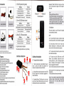
2.1 Red LED (power/working status)
Backwards). When the SIM card is ready you will hear a
click. Or else please insert again and then replace the
silicon seal.
Continuouslv in dark state
Low batterv / oower off
GPS status LED
Note:
Pleaser'use GSM network SIM
caid. .r i.i., , . .
Poweioff before installrin,g ot remoying the,Sl.M,qaid.
GSM status LED
Power/ working status LED
',.:
The S,l,M. card used shciuld be enabledrfor G:P.R$r:' . r
The SIM card used should be enabled for called lD.
lf there is a power on password, or pin, please cancel it;
Ensure the SIM card can send and receive SMS.
.
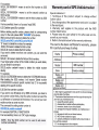
2.2 Green LED(GSM status indicator)
lltti::itt.i.it:ii:t':i,ti,.it:t.li.:i::u:,:l,,tt:tt;l;tlrtlliiiii:
rdLL
:s;
::lrliiiirii$8$S&ilii!:lil1l
iiilliiiirirllll
i:i|iiiitiiiriilitililltl*lg3Illilliriiir:t::llii
Meanino
LED Status
Ouick flashino (interval 0.'ls)
GSM initialization
Slow flash i nofflash 0- 1 s after everv 2s
GSM
Continuouslv in briqht state
3Slvl conversation/Start GPRS
Continuouslv in dark state
No GSM siqnal
2.3 Blue LED (GPS status indicator)
LED Status
Flashino (interval 0.1
Continuously in briqht state
Continuouslv in dark state
Meanino
Searchino GPS sional
GPS located
GPS not located
4.2 lnstallation
.,-O
l'ffirffi )+
The device installation is covert. Please refer installation
to an auto electrical contractor.
f*)q
(3ry
NOTE:
4.2.1 fo prevent theft of the device, it should be installed
]
as covertly as possible. Covertly installation is suggested.
4.2.2 Avoid placing the device close to hrgher power
electrical devices,such as reversing radar, anti-theft
2.4 lgnition detection indication
device or other vehicle communication equipment;
Three (blue/red/green)LEDs are in cycling flashing.
4.2-3 The device should be fixed into position with cable
ase check the accessories before using.
tures are for indication and illustration purposes only.
Features:
ties or wide double-side tape.
3. lnterface
introduction
iSM 850/900/'l 800/1 900 Quad band
Ai ide for voltage input range: 9-36vDC
iPS continuous positioning, GPRS timing interval
lheck location via SMS
luiltin vibration sensor, theftproof
tCC ignition detection
-ele-cutoff (petrol/
electricity) function
-hree
SOS numbers in maximum
iOS alarm and burglar alarm
/oice monitor function
\larm when the power supply is disconnected intentionally
ith backup battery)
)ompatible with external connection through (serial port)
ieo-fence via sms command
4. Method of installation
m
4.2.4 The device has built-in GSM antenna and GPS
antenna. During installation, please make sure the
4.1. Preparation before installation
^"F*."
4.1.1 Open the packing box to check whether the type of
device is correct and whether the accessories
are
included, or else please contact your distributor.
g
".H""
."m"".
4.1.2 Choose SIM card: each device needs to insert a GSM
SIM card. Please refer to the distributor's suggestions to
receiving side face is up, with no metal object above the
to interfere with GPS reception. The following
places are suggested for installation:
-shelter in the decorated board below the front windshield;
device
-shelter around the front instrument panel (non-metallic
materialface);
-in the decorated board below back windshield;
choose the SIM card.
4.1.3 lnstalling SIM card: The Sl[/ card slot is on the right
side of device. Open the SIM card silicon seal, then insert
the SIM card to the slot (do not insert the SIM card
Notice: if the windshield is pasted with metal thermal:i
protective coating or heating.coatinO; lt may affect,.,the
receiving signal. ln this .rcase, , please ,,ch'ange ,the
installation place.
J Device
outlet specification
5. Cautlone of devlce wiring
5.1 Power/ACC/Tele-cutoff(petrol/electricity) control
4.4 Device wiring diagram
line (4 pin)
1
2
3
5.1 .1 The standard voltage is 9V-36VDC. Please use the power
4
6
7
line which provided by the manufacturer. The red line is the
positive. Th€ black line is the negative. The negative should
earth alone or link iron during installing. Do not connect it to
8
other ground wire.
5
I
5.1 .2 ACC line (orange) is connected to the ACC switch o1
the vehicle. Please make sure to connect the ACC line.
The tracker will decide whether to enter ignition detection
according to ACC status. lf do not connect to ACC line, the
device will enter ignition detection status. lf the vehicle
vibrates when moving, it will activate the vibration alarm. lf
there is no need for the theftproof function, connect the
ACC line to the positive in parallel and keep high level5.1.3 Tele-cutoff (petrol/ electricity) control line (yellow) is
connected to pin 86 of the Tele-cutoff (petrol/ electricity)
relay (equal to the yellow line of the relay socket).
10
11
Soecificatior
2
4
Color
Keypod
MIC-.MlC+
TX
RX
GND
MOTOR
ACC
Black/ Red
Green
White
Black
Yellow
Oranqe
BIack(thick)
Red(thick)
1
lnstruciion
Connect to SOS button
Connect lo Microohone
Sendanq data (TX)/backu
Receiving data (RX)/backup
Ground wire
Connect to relay control line
Connect to ACC ignition
Vehicle'l2V/24V negative
storage battery
Vehicle 12Vl24V positive
storage battery
,tes of the relay wiring
,. relay wiring of pump: oil connectors of both ends are a
) white line (85) and a fine yellow line (86). The fine white
! (85) is connected to vehicle positive power (+12V). The
r yellow line is connected to the device relay control line.
I off the positive connection line of the pump; then connect
ieries to the relay N.C. contact (thick green line 87a) and
other end to relay COM contact (thick green line 30).
)te: The standard relay is 12V and only suits the 12V
iilrlb-a!!91y,r
ill€riV.r"'
plsase choose 24Y relay if it is 24V. cai,,
."',
I
2A FUSE
fuse box
llgnition
I
k"v
t
il
i.L
@:]^^,
12Vt24V
relay
Pump
N
N
is the APN of
APNiAPN,rame,user name,password#
E. g: APN,intemeLCLIENTE,AMENA#
6.2 DNS setting
To connect other platform, please send the two SMS
commands bleow:
Command format:
ln DNS way:eAPN,APN's Name#
@SERVER, l,DNS,Port,o#
Or in lP way: eAPN,APN's Name#
@SERVER,0,tBPort,0#
E.g:
ln DNS way:
APN,internet#
SERVER, 1,www.cooaccess.net,8841,0#
Firmware updating interface/expanded function to reserve
APN,internet#
6. Parameter setting
The SMS command is divided by comma. There is a reply
SMS after sending the command. lf set successfully, there
is a "ok" reply SMS; or else please set again.
The device will reply the corresponding information after
sending the SMS command.
Any phone numbers can send SMS command to the devrce
as default-
6.1APN setting
carrier)
Note TheAPNtiof someicouRties:have user name and,pdssword, iyoiil
may need to serd SMS cornmand as follo ring:
5.2 USB cable (3 pin)
space.
5.3 MIC line (2 pin)
Externally con nect to microphone for voice mon itor fu nction.
5.4 SOS line (2 pin)
Externally connect to SOS switch for SOS function.
Connect lo
E.g: APN,internet# ("internet"
The device will reply "OK" if setting successfully.
Or in lP way:
SERVER, 0,59.1 88.23.235,8841 ,0#
It will reply "OK" after set successfully.
6.3 ON /OFF GPRS
When you want to disable GPRS, you can SMS command
to the SIM card numberwhich used in the device.
Command format:
GPRSON: GPRSON,I#
GPRSOFF: GPRSON,O#
It will reply "OK" after set successfully.
6.4 Add specific number
SMS command to the device to set the SOS number.
SOS,A,No.1,No.2,No.3#
To connect default platform www.cootrack.net, please send
"A" means to add new numbers, for example:
sos,A, 1 351 0905991,'l 35'l 0905992, 1 351 0905993#
the SMS command below:
APN command format: APN,APN'S Name#
number as SOS number. And the null means no adding.
lf there is only one SOS number, you can appoint a specific
For example:
SOS,4,13510905991# means to set the first number as SOS
Warranty,,saf d,,of GPS',VChicle,t racker
SOS,A,,13510905992# means to set the second number as
Special statement
1. Technique of this product subject to change without
further notice.
2. Any change about the appearance and color is subject
to the real object.
3. Warranty card applies to the product with the lMEl
number listed below.
4. Please keep this card safely for the after-sale service,
as well as your receipt.
5. Refer to the table below for the warranty reference.
This card is the basic certificate for warranty, please
fill it carefully and keep it safely.
number
SOS number
SOS,A,,,13510905993# means to set the third number as SOS
number
lf set successfully, there is a "success" reply SMS.
6.5 Delete specific number
Before deleting specific number, please check its corresponding
code. For the code, please SMS "PARAM#' to the device.
SMS command to the device to delete the number.
SOS,D,serial NO.l,serial NO.2,serial NO.3#
"D" means to delete the number, for example:
SOS,D,1# means to delete the first number
SOS,D,3# means to delete the third number
lf you want to delete more than one numbers, you can send this
command:
SOS,D,1,3# means to delete the first and third numbers.
lf you forget serial number of the mobile number you want delete,
you can send this command:
SOS,D,mobile numbe# means to delete the mobile number
directly.
For example:
SOS,D,1 3527852360# means to delete the
1
3527852360 directly.
After deleting the SOS number, it will receive "Delete number
l3sXXXXXXXX success! speciflc number total 2" for successful
deleting of the speciflc number.
6.6 Set the center number
lf you want to cut off/restore oil by SMS command, you have to
set a center number firstly. Only the center number can send the
cut off/restore oil command to the device. You can set your own
mobile number as center number.
The command for setting center number is:
CENTER,A,mobile number#
For example:CENTER,A, 1 594270340 1 #
lf set successfully, there is an "OK" reply message.
NOTE: Only the SOS number can be used to sel center
number successfully.
:
Name
rhone numbe
Address
Model
Date
Sales unit
lMEl number
nvoice numbe
Sales unit
sales unrt
:hone number
Main engine is guaranteed forone yearfor non-human damage
nce the date ofpurchase.
The situations listed below are not in the scope ofwarranty, the
rer has to pay maintenance cost:
1 ) exceed the warranty period;
2 ) disassemble or maintein withourauthorization;
3 ) immeEion, break or bum ofcircuit board;
4 ) damages from imprcper installatio, use, maintenan@ or
orage;
5) damages of shell, lensorinternal anlenna;
6 ) ll\rEl number is teared or vague;
7 ) waranty certilicate is in@nsistent with product model, or
e certmcate is altered;
8 ) the damages due to force majeure.
Maintenance records
Record one
Maintenanc€
unit
Date
Fau lt
description
l\/lainfanannr
status
lMEl numbe
Date
Fault
description
\4aintenancr
status
lMEl numbe
6.9 Check GPRS parameters
SMS command to the device to delete the center number.
The command is:CENTER,D#
For example:CENTER,D#
lf set successfully, there is an "OK" reply SMS.
SMS command
lservicemanl
format: GPRSSET#
Eg: GPRSSET#
Reply message:
GPRS:ON
//GPRS on/offstatus//
NOTE; Only the SOS number can be used to delete center
APN:CMNET,0,0.0.0.0,,;
number,.. ctan ,send. ihi:s ,qtomrm:anld,l.]
successfully 10 set the center number. There is only one
center number can be set.
Server:1,egt06.szdatasource.com,8841,0; //platform information//
URl:http://maps.google.com/maps?q=; //preset web link setting
number successfullv.
Only SOS phonci
//APN setting information//
information //
6.8 Check parameter settings
6.10 GPRS time interval
SMS the command to the device to check the device setting.
Command format: PARAM#
e.g.: PARAN/#
Reply information:
I MEI : 35341 SO3XXXXXXX
// I MEI number of the device//
The default GPRS time sending interval is 10s which means the
device will upload positioning data to the platform server every 1 0s.
Users can modify GPRS time sending interval by SMS
'TlMER,time(second)#".
GPRS lnterval:10; //GPS data uploading lnterval, the time ranges
from 1018000s, default as 10s
TIMESET2o; //the GPS working time when ACC is OFF, the time
range from 1-999mins(default as 20 min//
SOS Number:
//
lservicemanl
Record two
unit
6.7 Delete the center number
'1.135po<xrooo<
2. 136xn<xn<n<
3. l3Txxxxxxx //maximum three SOS numbers used lor alarmll
Center Number: I 59427 03401
//only one center number
used for cutting off and restoring oil command//
Sensor time interval:10,180; //sensor detecting time, default as 10s;
vibratro
alarm delay, default as 1 80s; the time ranges from10-300s//
Sensor alarm time interval:10; //sensor alarm time interval, the time
ranges fiom 160mins; default as 10mins//
TlmeZone:E,8,0; //set time zone; default as E8//
It contains lMEl number/ GPRS lnterval/ TIMESET/ SOS/ CENTER
number/ Sensor time interval/ Sensor alarm time lneterval/'l-imezone
Note: Onlv SOS number canrsend SMIS commahd to s6t
delete ceiter number.
a,ridli
l
The time ranges from 10-18000s
For example: TlMER,10#
It means the device will upload data to the server every 10s.
I
6.1 1 Sensor alarm time setting
When the vehicle power is off and ACC is in low-level, if ACC is ofi
over 10 minutes, the device will enter sensor alarm state. ln this
case, if the vehicle vrbrates for a few times, it will activate the
vibration alarm systern. lf the vehicle battery is still not on (ACC is in
low level) after 3 rninutes, the device will start vibration alarm.
SMS format: "DEFENSE,TIME(minutes)#" The time ranges from 1
to 60 mins.
For example: DEFENSE,I S#. lt means when ACC is in low level for
1Smins, itwill enter sensor alarm status (vehicle power is off)
NOTE:
t .,rFreS!! SgS- nuribetsttwhen Eend rSM,$ .alarm
'messagreg
a,laimr,. plq?Ee 'SMS
and calls
ib6re,.is Iao. need'.foi virbiaticin.r
2-lf
SENSOR,0# to close it.
6.12 Restore to factory setting
SMS command format "FACTORY#" to set all parameter to default
factory value. Once received "OK", it succeeds.
i.1 3 Reboot device
7.3 SOS alarm
rVhen there is something wrong with the link of GPRS, e.9., The
)arameter setting of the device is conect, but you can't track the car
rn the platform. At this moment you can send a command to the
ievice to reboot the device.
[heformat is: RESET#
\fter receiving this command, the device will reboot after 1mins.
l. Operation of device
2.1
ln emergent case, press SOS for 3s to activate SOS alarm. Then the
device will send SOS SMS to preset specific numbers and then dial
the numbers in circles until the call is picked up. At the meantime, the
device will upload SOS alarm data to the server. And it will send:
SOS Alarm! <DateTime:11-06-17 14: 53:06>,
e.g.: Sensor Alarm! <Date'l'ime:11-06-17
http://maps.google.com/maps?q=N2257 67 1 3,E11 3.91 6585
http://maps. google.com/maps?q=N2257
Poweron/Poweroff
)ower on: Once insert a valid SIM card and connect all the wires,
um on the device, then Power LED will flash frst, During signal
iearching process, GSM and GPS LED will flash. Once GPS LED
leeps solid light, it means the device has been located and it starts
work.
)ower off: Just turn ofi the power switch.
o
.he device
will begin to upload positioning data to seruer once
lserting a valid SIM card and power on. During the working time, it
;an upload data to server every 10 seconds.
'z.2 Check location
'.2.1 Via SMS
:xample:
.at:N22.571285, Lon:E 1 1 3.8771 15,Cowse'.42.20, Speed:0
0740, DateTime :1 O-1 1 -23 22:28:51
'.2.1.2 SMS "URL#", to the SIM number of device. The
evice will send a location Google Map link. lf the device
oes not search any information of location, it will send
No data" to the cell phone.
:xample:
:Date Ti me
:
1 0
-
ma ps?q = N 22. 57
1 1
1
90,E1
7
.4 Wire
cut-off alarm
1
3.87
>
http ://maps. google.com
7
03
1
'.2.3Via platform
io to the platform website offered by dealers to check your
ehicle location.
14: 53;
06>,
67 1 3,E11 3.9 16585
Nole: The s.peclfic nu.mbers shoul.d be presel,ijust refer to 6;4
SMS "SENSOR,0#'to turn off vibration alarm.
7.7 Yoice monitoring
When the electricity supply of device is cut off, it will activate cut-off
alarm. ln this case, the device will send related SMS to the specific
numbers and dial the numbers in circles. lf nobody answers, the call
just keeps 3 loops at most. At the meantime, the device will upload
SOS alarm data to the server. And it will send:
Cut Power! <Date Time:11-06-17 14: 53:
06>,
67 1 3,E1 1 3.91 6585
NOte: T.he speqilic.nu.mbers should be preset, just refer to 6.4
7.5 Low battery alarm
When the device is only working with battery once the internai
voltage of battery is less than 3.7V, device will send low battery alarm
sms to specific number and alarm on platform.
Low battery alarm sms content example: 'Attentionl!lbattery too low,
please charge." Which means the battery is to low, to inform user
charging it in time.
Nole: The'speeifii.numbers shoul.d be preset,
-23 23:42:51
4
Note: The specific numbers should be preset. just refer to 6.4
http://maps. google.com/maps?q=N2257
'.2.1.1 SMS "WHERE #", to the SIM number of device. The
levice will send a location message automatically. You can
tet the coordinates. lf the device does not search any
lformation of location, it will send "No data" to the cell phone.
later 3 minutes, vehicle power is still otr ( ACC status is low device
will start alarm ) . At this time, it will send alarm SMS to SOS specific
number, and dial the SOS specific number in cycle until through. lf
nobody answers, the call just keeps 3 loops at most. The tracking
platform will also receive vibration alarm message.
juit
refer to 6-4
When the special number cell phone dial device, ringing for 10
seconds, it will enter voice monitoring status. At this time, caller can
monitoring the sound in vehicle. lncoming call from non special
numberwill not activate voice monitoring function.
this function. please set special number
,The.SlM.card put into the deyice should be equipped,wilh.,
No.te:To realize
beforeha nd.
caIer toenltltcaUon.
7.8 Oilcut-off
7.8.1. Via platform
Send oil cut-off command on platform. To make sure the security of
vehicle, tracker can only indicate to cut off oil when GPS is in valid
position status, and the speed is less than 20KM/H or in static.
Platform account password is needed when sending oil cut off
command.
7.8.2. Via SMS
7.6 Vibration alarm
Firstly, you should set a center number. Please refer to 6.6.Only
center number can send the command to the device to cut off and
When vehicle power is off, ACC status is also low, and if the lead
time of low ACC is more than 10 minutes ( settable ) , device will
activate security alarm. When the security alarm is on, once the
vehicle vibrates for several times, the alarm will be activated. in the
restore oil.
The format is: RELAYI#
After the command is carried out, it will reply "Cut off the fuel supply:
Success! Speed:0 Km/h". lf the command didn't cary out, it will repiy
the reason about fail to carry out.
Note: To ensure the safety of the driver and the car. this
command is valid only under two conditions: the GPS is
located: the speed is leiis than 20km/h
7.9 Restoring Oil
7.9.1. Via platform
When the- alarm is..off, sending recover oil.commands manually.
Device will restore oil supplying, and vehicle will work normally again.
Platform account password
command.
is needed when sending oil-cu-t off
7.9.2. Via SMS
Only center number can send the command to the device to restore
oil.
The format is: RELAYo#
After the command is carried out,
it will receive
"Restore fuel
supply:Success!"
7.1 0 Over speed
Alarm
When the car is moving over a limited speed in average in a limited
time period, then the device will send over speed alarm SMS to user.
To tum on the over speed function, please send below SMS
command: SPEED,Time,Limited speed#
:'1-10
Limited speed range ( km/ir ) :0-255 (0 referstotum offoverspeed
alarm functron)
Example: SPEED,3,120#
Means when the car is moving over 120km/h in average in 3 minutes,
the device will send over speed alarm to user.
limerange ( Minute )
8. Web based tracking online activation
The GPRS web based tracking platfonn allows real trme tracking
with the latest Google maps. There is also a playback feature that
allows you to view where the vehicle has been for up to 30 days in
the past making it ideal forfleet management.
9. Trouble shooting
9.1. After installing it in the first time, if device can not get connected
with platform server, at this time it is "logged of' status in platform.
Please check the installation of device:
1
)Check whether the connection of powerJine is conect, please do
not connect itwith the carcontrol line.
2)Check whether SIM card is installed conecty, please refer to the
installation manual;
3)Check whether the power switch is toggled to 'ON", the switch is in
the left of the SIM card's slot.
4)WhetherACC ignition cable is connected, please tum on the ACC
with key after it is connected.
S)Check the LEDs' status. ln normal working status, the red LED is in
solid bright or flashing; green LED and blue LED are both in solid
bright.
6)Check whether GPS is located, if not, please drive to the open
areas for positioning.
First of all, check the three LEDS' status. lf it is not convenient to
that,
please check the SIM card status
:
)Call the SIM card number of the device to check whether you can
get through;
1
2)Check whetherthe vehicle is in no GSM area, such as basement;
3)Check the GSM/GPS disconnection area, whether
it is
all
disconnected or few of them disconnected, to make sure whether it
is the fault of operato/s intemet.
4)Check whether your SIM card charge is overdue;
5)Check whether the SIM card supports GPRS;
6)Check the parameter setup, whether the device lMEl number,
GPRS sending interval is correct;
9.3 lf the device'GPS function is normal, but can not locate for a long
time, please check whetherthe installation setup of device is conect:
1) Please make sure the GPS antenna face is up;
2) Please make sure there is no electromagnetic wave- absorbent
object (metal) above the device, especially the thermal-protective
coating on the windshield, it may affect the GPS reception of the
device;
around to interfere with GPS reception), please drive to the open
areas for positioning. Generally, it needs 1-2 minutes to receive the
first coordinates.
9.5 lf GSM can not receive the signals normally, please check
whether SIM card is installed correctly or there is no GSM signal at
the location you are, such as basement parking, please drive to a
place covered by GSM signal reception.
9.6 When cellphone with special number receives tele- cutoff alarm
sms, please make sure whether it is illegal wire cutoff, or the FUSE
on power line is blown. lf the FUSE in it is blown, please contact
your distributor to exchange with the same model FUSE, after the
intemal trouble is shoot, it can be power on to work again.
9.2 lf it is "offline" status in platform:
check
9.4 lf GPS can not receive the signals normally (there is high building


![東部ライテック総合カタログ(PDF)[4451KB・48ページ]](http://vs1.manualzilla.com/store/data/006682433_2-561a514b764f87f63077235acf70aa8c-150x150.png)