1
TM
NewStep
Motion Control System
User’s Manual
2
Preface
Preface
3
EU Declaration of Conformity
We declare that the accompanying products, identified with the
mark,
complies with requirements of the Electromagnetic Compatibility Directive,
89/336/EEC and the Low Voltage Directive 73/23/EEC.
Model Number: New Step Controller model NSC200.
Year
mark affixed: 2005
Type of Equipment: Electrical equipment for measurement, control and
laboratory use.
Standards Applied: Compliance was demonstrated to the following standards
to the extent applicable:
BS EN61326-1: 1997+A1+A2 “Electrical equipment for measurement, control
and laboratory use – EMC requirements.”
This equipment meets the CISPR 11 Class A Group 1 radiated and conducted
emission limits.
BS EN 61000-3-2:2001, Harmonic current emissions, Class A.
BS EN 61000-3-3:2002, Voltage fluctuations and flicker.
BS EN 61010-1:1993, A1+A2 “Safety requirements for electrical equipment for
measurement, control and laboratory use.”
Alain Danielo
VP European Operations
Newport Corporation
Zone Industrielle
45340 Beaune-la-Rolande, France
Dan Dunahay
Director of Quality Systems
Newport Corporation
1791 Deere Avenue
Irvine, CA 92606, USA
4
Preface
Warranty
Newport Corporation warrants that these products will be free from defects
in material and workmanship and will comply with Newport’s published specifications at the time of sale for a period of one year from date of shipment.
If found to be defective during the warranty period, products will either be
repaired or replaced at Newport's option.
To exercise this warranty, write or call your local Newport office or representative, or contact Newport headquarters in Irvine, California. You will be given
prompt assistance and return instructions. Send the products, freight prepaid, to
the indicated service facility. Repairs will be made and the products returned
freight prepaid. Repaired products are warranted for the remainder of the
original warranty period or 90 days, whichever occurs first.
Limitation of Warranty
The above warranties do not apply to products which have been repaired or
modified without Newport’s written approval, or products subjected to unusual
physical, thermal or electrical stress, improper installation, misuse, abuse, accident or negligence in use, storage, transportation or handling. This warranty also
does not apply to fuses, batteries, or damage from battery leakage.
This warranty is in lieu of all other warranties, expressed or implied, including
any implied warranty of merchantability or fitness for a particular use. Newport
Corporation shall not be liable for any indirect, special, or consequential
damages resulting from the purchase or use of its products.
© 2005 by Newport Corporation, Irvine, CA. All rights reserved. No part of this
manual may be reproduced or copied without prior written approval of Newport
Corporation. First printing 2005
This manual is provided for information only, and product specifications are
subject to change without notice. Any change will be reflected in future
printings.
Newport Corporation
1791 Deere Avenue
Irvine, CA, 92606, USA
Part No. 41793-01, Rev. A
Preface
5
Confidentiality & Proprietary Rights
Reservation of Title
The Newport programs and all materials furnished or produced connected therewith ("Related Materials") contain trade secrets of Newport and are for use only
in the manner expressly permitted. Newport claims and reserves all rights and
benefits afforded under law in the Programs provided by Newport Corporation.
Newport shall retain full ownership of Intellectual Property Rights in and to all
development, process, align or assembly technologies developed and other derivative work that may be developed by Newport. Customer shall not challenge,
or cause any third party to challenge, the rights of Newport.
Preservation of Secrecy and Confidentiality and Restrictions to Access
Customer shall protect the Newport Programs and Related Materials as trade
secrets of Newport, and shall devote its best efforts to ensure that all its personnel protect the Newport Programs as trade secrets of Newport Corporation.
Customer shall not at any time disclose Newport's trade secrets to any other
person, firm, organization, or employee that does not need (consistent with
Customer's right of use hereunder) to obtain access to the Newport Programs
and Related Materials. These restrictions shall not apply to information (1)
generally known to the public or obtainable from public sources; (2) readily
apparent from the keyboard operations, visual display, or output reports of the
Programs; 3) previously in the possession of Customer or subsequently developed or acquired without reliance on the Newport Programs; or (4) approved
by Newport for release without restriction.
Service Information
This section contains information regarding factory service for the source. The
user should not attempt any maintenance or service of the system or optional
equipment beyond the procedures outlined in this manual. Any problem that
cannot be resolved should be referred to Newport Corporation.
6
Preface
Technical Support Contacts
North America & Asia
Europe
Newport Corporation Service Dept.
Newport/MICRO-CONTROLE S.A.
1791 Deere Ave.
Zone Industrielle
Irvine, CA 92606, USA
45340 Beaune la Rolande, FRANCE
Telephone: (949) 253-1694
Telephone: (33) 02 38 40 51 56
Telephone: (800) 222-6440 x31694
Newport Corporation USA Calling Procedure
If there are any defects in material or workmanship or a failure to meet specifications, promptly notify Newport's Returns Department by calling 1-800222-6440 or by visiting our website at www.newport.com/returns within the
warranty period to obtain a Return Material Authorization Number (RMA#).
Return the product to Newport Corporation, freight prepaid, clearly marked with
the RMA#, and we will either repair or replace it at our discretion. Newport is
not responsible for damage occurring in transit and is not obligated to accept
products returned without an RMA#. Email: [email protected].
When calling Newport Corporation, please provide the Customer Care
Representative with the following information:
• Your Contact Information
• Serial number or original order number
• Description of problem (i.e., hardware or software)
To help our Technical Support Representatives diagnose your problem, please
note the following conditions:
•
•
•
•
Is the system used for manufacturing or research and development?
What was the state of the system right before the problem?
Have you seen this problem before? If so, how often?
Can the system continue to operate with this problem? Or is the system nonoperational?
• Can you identify anything that was different before this problem occurred?
Preface
7
Table of Contents
EU Declaration of Conformity .......................................................... 3
Warranty............................................................................................ 4
Confidentiality & Proprietary Rights ................................................ 5
Technical Support Contacts............................................................... 6
Table of Contents .............................................................................. 7
List of Figures ................................................................................... 9
1
1.1
1.1.1
1.1.2
1.1.3
1.2
1.2.1
1.2.2
1.3
Safety Precautions
11
Definitions and Symbols ................................................................. 11
European Union CE Mark............................................................... 11
C-US CSA Mark ............................................................................. 11
Direct Current (DC) ........................................................................ 12
Warnings and Cautions ................................................................... 12
General Warnings............................................................................ 13
General Cautions ............................................................................. 13
Manual Conventions ....................................................................... 13
2
2.1
2.2
2.3
2.4
2.5
2.6
2.7
2.8
2.9
Features & Specifications
15
NewStep™ System Overview......................................................... 15
NSC200 Controller / Driver ............................................................ 16
NSC-SB Switchbox......................................................................... 19
NSA12 Linear Actuator................................................................... 21
MFA-PP Motorized Linear Stage.................................................... 24
NSC-PS25 Power Supply................................................................ 28
NSC-JB RS485 Junction Box.......................................................... 30
NSC-485-232-I RS485-to-RS232 Converter................................... 31
NewStep™ System Environmental Specifications ......................... 32
3
3.1
3.2
3.3
3.4
3.5
3.6
Getting Started
33
Unpacking and Handling................................................................. 33
Inspection for Damage .................................................................... 33
Inventory of Parts ............................................................................ 34
Installation Location........................................................................ 34
Interconnecting NewStep Components ........................................... 35
Connection to Non-NewStep Components...................................... 41
8
Preface
4
4.1
4.2
4.3
4.3.1
4.3.2
Local Operation
43
Operating Modes ............................................................................. 43
Manual User Controls...................................................................... 44
Reading the LED Status Lights ....................................................... 45
LED Indicator on NSC200 Controller ............................................. 45
LED Indicators on NSC-SB Switchbox........................................... 45
5
5.1
5.2
5.3
5.4
5.5
5.6
5.6.1
5.6.2
5.6.3
5.6.4
NewStep-Util Software
47
Overview ......................................................................................... 47
RS232 Communications Setup ........................................................ 47
Software Installation........................................................................ 48
Controller Initialization ................................................................... 49
Network Scan .................................................................................. 50
Working with the Main Screen........................................................ 51
Setup Tab......................................................................................... 53
Move Tab......................................................................................... 55
Status Tab ........................................................................................ 56
About Tab........................................................................................ 57
6
6.1
6.1.1
6.1.2
6.1.3
6.1.4
6.2
6.3
NewStep ASCII Command Set
59
Command Set Introduction.............................................................. 59
LabView Support............................................................................. 59
Address Field................................................................................... 59
Set or Query Commands.................................................................. 60
Saving Settings to Non-Volatile Memory ....................................... 60
Command Set Summary .................................................................. 60
Command Set Details ...................................................................... 62
7
7.1
7.2
7.3
Maintenance & Service
99
Enclosure Cleaning.......................................................................... 99
Technical Support............................................................................ 99
Service Form ................................................................................. 101
Preface
9
List of Figures
Figure 1:
Figure 2:
Figure 3:
Figure 4:
Figure 5:
Figure 6:
Figure 7:
Figure 8:
Figure 9:
Figure 10:
Figure 11:
Figure 12:
Figure 13:
Figure 14:
Figure 15:
Figure 16:
Figure 17:
Figure 18:
Figure 19:
Figure 20:
Figure 21:
Figure 22:
Figure 23:
Figure 24:
Figure 25:
Figure 26:
Figure 27:
Figure 28:
Figure 29:
Figure 30:
Figure 31:
Figure 32:
Figure 33:
Figure 34:
Figure 35:
CE Mark ..................................................................................... 11
CSA Mark ..................................................................................... 11
Direct Current Symbol................................................................... 12
NSC200 top and bottom views ...................................................... 18
NSC-SB Switchbox, Front and Side .............................................. 19
Switchbox Connections ................................................................. 21
NSA12 Liner Actuator................................................................... 22
Mounted NSA12 ............................................................................ 22
Dimensions, NSA12 Linear Actuator ............................................ 23
Single MFA-PP Linear Stage......................................................... 25
Stacked MFA-PP Linear Stages..................................................... 25
Dimensions, MFA-PP Motorized Linear Stage ............................. 26
MFA-TP Top Plates....................................................................... 26
MFA-BK Top Plate ....................................................................... 26
MFA-BP Base Plate....................................................................... 27
NSC-PS25 Power Supply to One load ........................................... 29
NSC-PS25 Power Supply to Multiple Loads ................................. 29
NSC-JB RS485 Junction Box ........................................................ 30
Branching with Multiple RS485 Junction Boxes........................... 31
NSC-485-232-I Converter ............................................................. 32
Connections, 1 Controller, 1 Supply.............................................. 37
Connections, 2 Controllers, 1 Supply ............................................ 38
Connections, 1 Controller, 1 Supply, Computer Control ............... 39
Connections, 2 Controllers, 1 Supply, Computer Control ............. 40
Connections, 1 Controller, 1 Switchbox, 2 Positioners.................. 41
NSC200 top and bottom views ...................................................... 43
Set Communication Port Screen ................................................... 48
Initialize Controller Screen ............................................................ 49
Initializing Another Controller Screen........................................... 49
Set Communication Port Screen .................................................... 50
View all Screen.............................................................................. 51
Setup Screen .................................................................................. 52
Move Screen .................................................................................. 55
Cycle Utility Screen....................................................................... 56
Status Screen.................................................................................. 57
10
Preface
Figure 36: About Screen..................................................................................58
1
Safety Precautions
1.1
Definitions and Symbols
The following terms and symbols are used in this documentation and also appear
on the NewStep Actuator and Controller where safety-related issues occur.
1.1.1
European Union CE Mark
Figure 1:
CE Mark
The CE mark indicates that the equipment has been designed and tested to
comply with all applicable European Union (CE) regulations.
1.1.2
C-US CSA Mark
Figure 2:
CSA Mark
The presence of the C-US CSA mark indicates that the equipment has been
designed, tested and certified as complying with all applicable US and Canadian
safety standards.
12
1.1.3
Safety Precautions
Direct Current (DC)
Figure 3:
Direct Current Symbol
This symbol indicates that the equipment is suitable for DC power only.
1.2
Warnings and Cautions
The following are definitions of Warnings, Cautions and Notes that may be used
in this manual to call your attention to important information regarding your
safety, to the safety and preservation of your equipment, and to important tips.
WARNING
Situation has potential to cause bodily harm or death.
CAUTION
Situation has potential to cause damage to property or equipment.
NOTE
Additional information the user or operator should consider.
Safety Precautions
1.2.1
13
General Warnings
Observe these general warnings when operating or servicing this equipment:
•
•
•
•
•
Read all warnings on the unit and in the operating instructions.
Do not use this equipment in or near water.
Only connect the power cord to a grounded power outlet.
Route power cords and other cables so they are not likely to be damaged.
Disconnect power before cleaning the equipment. Do not use liquid or aerosol
cleaners; use only a damp lint-free cloth.
• To avoid explosion, do not operate this equipment in an explosive atmosphere.
1.2.2
General Cautions
Observe these cautions when operating or servicing this equipment:
•
•
•
•
•
Use only specified replacement parts.
Follow precautions for static sensitive devices when handling this equipment.
This product should only be powered as described in this manual.
There are no user-serviceable parts inside the NewStep system components.
If this equipment is used in a manner not specified within this manual, the
protection provided by the equipment may be impaired.
• Do not position this equipment in a location that would make it difficult to
disconnect the AC power cord.
1.3
Manual Conventions
The following conventions are used in this manual:
• Acronyms appear on the first occurrence enclosed in parentheses following
their definition. An acronym is a word formed from the initial letters of a string
of words. Example: Read Only Memory (ROM).
• Italics or boldface text are used as an alternative to quotation marks to highlight special text, such as keyboard keys, onscreen buttons, or text entries.
Examples: Press Enter. AU command.
2
Features & Specifications
2.1
NewStep™ System Overview
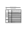
Newport’s NewStep family of motion controllers and positioners are designed
to provide affordable, motorized fine-positioning of mechanical stages and
optical mounts in a wide range of optomechanical systems. NewStep system
components (as of February 2005) include the following:
MODEL
DESCRIPTION
NSC200
Hand-held motion controller/driver with manual controls
and an addressable RS485 computer interface.
NSA12
Miniature linear motorized actuator, 11 mm travel.
MFA-PP
Motorized linear Stage, 25 mm travel.
NSC-PS25
AC power supply.
NSC-PSC1
1 meter (3 ft) power supply output cable.
NSC-PSC3
3 meter (10 ft) power supply output cable.
NSC-485-232-I
RS485-to-RS232 converter.
NSC-JB
Junction box to split 1 RS485 channel into to 5 channels.
NSC-CB1
1 meter (3 ft) RS485 cable.
NSC-CB3
3 meter (10 ft) RS485 cable.
NSC200-KT
NewStep kit including NSC200 controller, NSA12 actuator,
NSC-PC25 power supply, NSC-PSC3 power supply cable.
16
Features & Specifications
NSC-SB
2.2
Switchbox allowing one NSC200 to drive up to 8
positioners. Included cables:
P/N 41791-01 1.8 m (6 ft) power cable to controller.
P/N 15769-02 1.8 m (6 ft) driver cable to controller.
P/N NSC-CB2 1.8 m (6 ft) RS485 cable to controller.
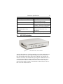
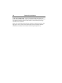
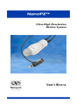
NSC200 Controller / Driver
The NSC200 is an integrated, single-axis, stepper motor controller/driver. It
is designed to be hand held but also provides through-holes for bolting to an
optical table with a 1” or 25 mm grid of mounting holes. Used by itself, the
NSC200 provides easy and affordable means to control a single positioner,
which can be an NSA12 linear actuator or MFA-PP linear stage. Ultra-smooth,
high-resolution positioning is provided by 64x micro-stepping and all-digital
control, which provides increased accuracy and reliability compared to potentiometer based designs.
Use of an external NSC-SB switchbox allows a single NSC200 to control up to
eight positioners one channel at time.
Two primary control modes are selectable whether or not a switchbox is used:
Local (manual control) or Remote (computer control). Selection of Local or
Remote is by pressing the knob of the NSC200. The control mode is indicated
by the color of a tri-color LED. Remote is the default mode at power-up. For
details on Local operation, see Section 4 of this manual.
Two secondary control modes are selectable whether the controller is in Local
or Remote mode: Velocity or Position. Velocity is the default mode at powerup.
In Velocity mode, the rotary knob at the front of the NSC200 is turned to select
one of eight (8) speed settings for each direction plus a rest position. Rotate the
knob in one direction, and the positioner moves in that direction. Rotate the
knob in the other direction, and the actuator moves in that other direction. The
farther the knob is rotated, the faster the positioner moves. The knob is springloaded and returns to its zero point when released, thus stopping motion.
In Position mode, the rotary knob is turned to its extreme clockwise or counterclockwise position. The controller then moves the positioner by a preset number
of micro-steps, either up or down.
Features & Specifications
17
Remote (computer) control makes use of the NSC200’s digitally addressable
RS485 port, which is interfaced to the RS232 COM port of a PC. The interface
is provided by an RS485-to-RS232 converter, an optional 1x5 RS485 junction
box, plus cables, all available from Newport. In Remote mode, the NSC200
accepts and executes ASCII commands. These can be issued in three primary
ways:
1. NewStep-Util software, distributed on CD with each NSC200. For details,
see Section 5 of this manual.
2. User-written LabView applications using drivers distributed on CD with
each NSC200. The drivers are compatible with LabView 5, 6 or 7.
3. Other user-written software that issues and receives ASCII commands, as
documented in Section 6 of this manual. For details, see Section 5 of this
manual.
Compared to the predecessor NSC100, the NSC200 offers a number of new
features and higher communication speeds. As a result, the versions of NewStepUtil software, LabView drivers, and ASCII command set developed for the
NSC200 are not backward compatible with the NSC100. It is however possible
to use NSC100’s and NSC200’s on the same RS485 network provided that their
respective software is used.
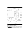
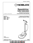
18
Features & Specifications
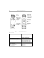
Control knob for:
• Velocity control
• Position control
• Channel selection
• Local or Remote
mode selection
Tri-color
status LED
V
P
Buttons to select:
• Velocity or
Position mode
• Switchbox
channel
Flat portion of
housing to seat
against optical
table
Reset button
for RS-485
address
Mounting holes
for bolts to
optical table
Figure 4:
NSC200 top and bottom views
Specifications
Number of controlled axes
1 without NSC-SB switchbox
8 with NSC-SB switchbox
Operating modes
1. Manual velocity mode.
2. Manual position mode.
3. Computer controlled mode.
Selection of manual or computer
Pressing down on control knob.
Controls, Local (manual) mode
1. Button to select velocity mode.
2. Button to select position mode.
3. Rotary knob to activate motion.
Controls, Remote (computer) mode
ASCII commands I/O via RS485 port.
Power requirements
When driving positioner
In standby mode
0.7A @ 15 Vdc
0.3A @ 15 Vdc
Features & Specifications
Power output when driving positioner
Compatible positioners
19
400 mA @ 15 Vdc
NSA12 linear actuator.
MFA-PP motorized linear stage.
Stepper motor control
64 micro-steps per full-step.
Connectors
Coaxial mini jack for power input
6-position, 4-wire RJ11 jack for RS485
9-pin mini DIN, female, to positioner
Mechanical
Dimensions (W x D x H)
Weight
50 x 150 x 50 mm (2” x 6” x 2”)
250 g (9 oz)
Environmental
See NewStep system specs
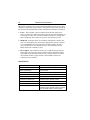
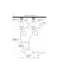
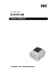
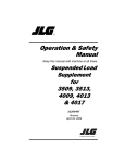
2.3
NSC-SB Switchbox
Figure 5:
NSC-SB Switchbox, Front and Side
The NSC-SB switchbox is a intelligent multiplexer (or switch) which allows one
NSC200 controller to drive up to eight NewStep positioners one channel at a
time. The controller mode can be either Local or Remote. In Local mode, the
channel is selected by first simultaneously pressing the V and P buttons for five
seconds, then pressing the V and P buttons individually to increment or decrement the channel. In Remote mode, the channel is selected under computer
control. In either mode, the status of each channel is indicated by the color of a
bank of tri-color LEDs labeled 1-8.
20
Features & Specifications
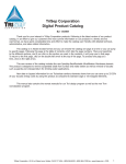
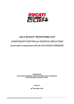
When used, switchbox serves as the connection hub between the power supply,
computer (if applicable), and positioners. The controller detects the presence of
the switchbox and automatically enables or disables functionalities as required.
• Power. The switchbox is powered directly from the NSC-PS25 power
supply via first power cable, and in turn powers the associated controller via
a second power cable. The side of the switchbox features two coaxial mini
jacks, one labeled with a symbol for power in, one labeled Controller.
• RS485 I/O. In Remote mode, the switchbox communicates with the computer via a first RS485 cable, and in turn communicates with the controller
via a second RS485 cable. The side of the switchbox features two RJ11
jacks, one labeled PC, one labeled Controller. In Local mode, only the
RS485 cable to the controller is used.
• Drive Signals. The switchbox can drive up to eight NewStep positioners,
and in turn is driven by the controller. The back of the switchbox features
eight female 9-pin mini-DIN connectors for positioner cables. The side of
the switchbox features a single female 9-pin mini-DIN connector for
connection to the controller.
Specifications
Positioner input channels
1 (multiplexed by switchbox)
Positioner output channels
8 (only selected channel is active)
Power requirements
15 Vdc, 40 mA
Channel status indication
One tri-color LED per channel
Case dimensions (H x W x D)
35 x 182 x 151 mm (1.4” x 7.2” x 5.9”)
Case material
Aluminum, painted.
Connector for power input
Coaxial mini jack, positive center.
Connector to computer (if used)
6-position, 4-wire RJ11 for RS485 I/O.
Connectors to positioners
8 connectors, 9-pin mini-DIN, female.
Connectors to controller
6-position, 4-wire RJ11 for RS485 I/O.
Coaxial mini jack, positive center, for power.
9-pin mini-DIN, female, for drive signal.
Features & Specifications
P/N 41791-01 1.8 m (6 ft) power cable.
P/N 15769-02 1.8 m (6 ft) driver cable.
P/N NSC-CB2 1.8 m (6 ft) RS485 cable.
Cables to controller
Figure 6:
2.4
21
Switchbox Connections
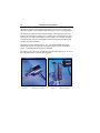
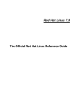
NSA12 Linear Actuator
Designed as micrometer replacement, the NSA12 linear actuator is ideal for
remote adjustment of sensitive, hard-to-reach optical mounts, which could be
influenced by the forces imposed by manual adjustment of micrometers. Typical
22
Features & Specifications
applications include optimizing the alignment of a laser cavity, zeroing in on
coherence lengths, or just adjusting the pointing of a beam over a long distance.
The NSA12 provides a motorized, linear plunger, whose position can be controlled with sub-micron resolution over 11 mm of travel. The plunger can drive
a load up to 28 N and is terminated by a non-rotating 5/32” chrome-vanadium
steel ball bearing. The drive mechanism incorporates a spring mechanism that
virtually eliminates backlash.
The NSA12 is easily mounted via its .375” x 40 pitch threaded shaft. This
mechanical interface is compatible with many Newport mounts and manual
stages. A mounting nut and wrench are included.
The NSA12 can be driven by an NSC200 controller either directly or via one of
the eight output ports of an NSC-SB switchbox.
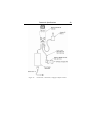
Figure 7:
NSA12 Liner Actuator
Figure 8:
Mounted NSA12
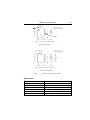
Features & Specifications
Cable
Lock Nut
Figure 9:
Dimensions, NSA12 Linear Actuator
Specifications
Diameter
Length
Provision for mounting
Actuating element
Limit switch
Travel range
Motor
30 mm diameter
66.1 mm retracted, 76.2 mm extended
.375-40 UNS-2A threads, nut included.
Plunger with non-rotating 5/32” ball tip.
Optical limit switch on motor side
11 mm
2-phase stepper motor, open loop
23
24
Features & Specifications
Drive mechanism
Drive screw pitch
Full-step
Micro-step (1/64 of full-step)
Minimum incremental motion
Unidirectional repeatability
Bidirectional repeatability
Load capacity
Max speed, no load
Weight
Length of drive cable
Cable connector
Vacuum compatibility
Housing finish
Environmental
2.5
Direct drive, non-rotating lead screw
0.3048 mm/revolution
6.4 µm (48 full-steps/revolution)
0.10 µm (1/64 of full-step)
0.30 µm (3 micro-steps)
2.2 µm
< 10 µm
28 N (2.9 kg-force or 6.3 lb-force)
1.0 mm/sec
0.1 kg (0.2 lb)
3 m (10 ft)
9-pin mini DIN, male
10-6 Torr (Model NSA12V6)
Black anodized aluminum (NSA12)
Natural aluminum (NSA12V6)
See NewStep system specs
MFA-PP Motorized Linear Stage
The MFA-PP motorized linear stage is an economical solution for space-limited
applications which require very high resolution, single-axis translation of up to
25 mm. Two stages can be stacked for two-axis XY, XZ or YZ control. Three
stages can be stacked for three-axis XYZ control, as shown in photo below.
MFA stages feature an all-steel construction that provides a higher stiffness-toweight ratio with lower thermal expansion than aluminum designs. The result is
superior performance in a smaller footprint. The smooth motion of MFA stages
is achieved by Newport's proprietary double-row linear ball bearing design with
bearing ways that are directly machined into the structural elements of the stage.
Compared to alternative solutions that use commercial bearings, MFA linear
stages offer a higher load capacity and stiffness with low pitch and yaw errors.
End-of-run limit switches prevent bearing damage from accidental over-travel.
Installation of an MFA stage on an optical table requires a Model MFA-BP
base plate. Optical components can be secured directly to the top surface of the
moving stage, which is small but provides 4 mounting holes with M2 threads
plus 6 mounting holes with M3 threads. Greater flexibility in mounting optical
Features & Specifications
25
components is provided by an add-on top plate. This is normally an MFA-TP
plate with Imperial threads or an M-MFA-TP plate with metric threads.
Two stages can be stacked directly for XY control. Stacking of stages for XZ,
YZ or XYZ control (with a vertically mounted stage) requires use of a single
MFA-BK top plate. This plate provides through-holes for tapped mounting holes
at the end of the fixed frame of the stage. Note that top and bottom mounting
plates are not included with the MFA stage, but must be ordered separately.
An MFA-PP stage can be driven by an NSC200 controller either directly or via
one of the eight output ports of an NSC-SB switchbox.
CAUTION
MFA stages contain delicate, factory-preloaded parts. Only operate
in a clean environment. Avoid mechanical shock. Never attempt to
disassemble the stage. Any unauthorized disassembly will void the
warranty. We recommend that you return the stage to the factory
after every 2000 hours of use for lubrication and readjustment.
Figure 10:
Single MFA-PP Linear Stage
Figure 11:
Stacked MFA-PP Linear Stages
26
Features & Specifications
Figure 12:
Dimensions, MFA-PP Motorized Linear Stage
Top plate used to stack MFA-PP for
Z-axis control.
Figure 13:
MFA-TP Top Plates
Figure 14:
MFA-BK Top Plate
Features & Specifications
Figure 15:
MFA-BP Base Plate
Specifications
Size (H x W x L)
Weight
Provision for mounting
Base material
Bearings
Drive mechanism
Motor
Drive screw pitch
Reduction gear
Limit switches
Travel Range
Full-step
Micro-step
Minimum Incremental motion
Unidirectional repeatability
Bidirectional repeatability
Home position repeatability
On-axis accuracy
Load capacity, vertical
Load capacity, along axis
Max speed, no load
Torsional stiffness, pitch
Torsional stiffness, roll
20 x 45 x 140 mm (.79” x 1.77” x 5.51”)
0.6 kg (1.5 lb)
Add-on top and bottom mounting plates
Stainless steel
Double row linear ball bearings
Backlash compensated lead screw
2-phase stepper motor
0.5 mm
1:43
One mechanical switch per direction
25 mm
0.485 µm
0.00757 µm (1/64 of full-step)
0.1 µm
0.5 µm
2.5 µm
4 µm
8 µm
50 N
10 N
0.3 mm/sec
60 µrad/Nm
100 µrad/Nm
27
28
Features & Specifications
Length of drive cable
Cable connector
Environmental
2.6
1.5 m (5 ft)
9-pin mini DIN, male
See NewStep system specs
NSC-PS25 Power Supply
The NSC-PS25 is a switching power supply designed to drive one or multiple
NSC200 NewStep controllers either directly or through an NSC-SB switchbox.
Input power can be 90-246 Vac, 47-63 Hz. Output power is 15 Vdc, 4.6A max.
A single NSC-PS25 power supply can drive multiple NSC200 controllers,
which consume 0.7A while driving a positioner and 0.3A in standby mode.
Power consumption is not materially affected by driving a positioner through a
switchbox. To determine the maximum number of NSC200 controllers that can
be connected to a single power supply, add the current draw of all controllers
that will be driving loads simultaneously to that of all controllers in standby
mode.
It is theoretically possible for a single computer COM port to command up to
32 controllers by daisy chaining multiple NSC-JB 1x5 RS485 junction boxes,
and all controllers could be driving loads simultaneously. In that case, current
draw considerations would limit the maximum number of controllers to 4.6A /
(0.7A/controller) = 6 controllers. When driving multiple positioners through an
NSC-SB switchbox, only one of the positioners is driven at a time by the
controller.
The NSC-PS25 comes with a 3 m (10 ft) DC power output cable, which is terminated by a coaxial DC power output connector with a 5.5 mm outer ground and
a 2.5 mm positive center. This connector can be plugged directly into the power
jack of an NSC200 controller or an NSC-SB switchbox, which will then in turn
power the controller. The connector can also be plugged into a power cable
which branches power to two (2) DC power output connectors. By daisy chaining branching power cables, it is possible to power multiple controllers or
switchboxes from the same supply.
Features & Specifications
Figure 16:
Figure 17:
NSC-PS25 Power Supply to One load
NSC-PS25 Power Supply to Multiple Loads
Specifications
Input voltage
Input current, max
Output voltage, nominal
Output current, max
Supply efficiency
Case size (H x W x L)
Length of DC power output cord
DC power output connector
DC power output branching cables
(optional)
NSC-PSC1
NSC-PSC3
Environmental
90-246 Vac
1.5A
15 Vdc
4.6A
85% (switching type)
30 x 58 x 132 mm (1. 2” x 2.3” x 5.2”)
3 m (10 ft)
Coaxial, 5.5 mm outer ground, 2.5 mm
positive center.
1 m, two DC power output connectors
3 m, two DC power output connectors
See NewStep system specs
29
30
2.7
Features & Specifications
NSC-JB RS485 Junction Box
The NSC-JB is a passive junction box which allows a single 6-position, 4-wire
RJ11 jack to be branched into up to five jacks. By using a single NSC-JB, a
single NSC-485-232-I converter connected to a computer COM port can command up to five digitally addressable NSC200 controllers. NSC-JB junction
boxes can also be daisy chained to increase the number controllers. The theoretical maximum number of controllers connected to a single RS-485 line is 32
for current drain reasons, as specified by the RS485 standard.
Physically, the NSC-JB consists of a white plastic case with five RJ11 jacks,
plus a 3.6 m (12-foot) cable terminated by an RJ11 plug. Two mounting ears
are provided. All like pins are wired in parallel, with no active components.
Figure 18:
NSC-JB RS485 Junction Box
Features & Specifications
Figure 19:
31
Branching with Multiple RS485 Junction Boxes
Specifications
Input connector (computer side)
Output connectors (controller side)
Signal processing
Environmental
2.8
6-position, 4-wire RJ11 plug
Five 6-position, 4-wire RJ11 jacks
None. Device is passive.
See NewStep system specs
NSC-485-232-I RS485-to-RS232 Converter
The NSC-485-232-I is a line-powered, half-duplex, RS485-to-RS232 converter,
which allows the RS232 COM port of a computer to command one or multiple
NSC200 controllers via a single RS485 line. A 6-position, 4-wire RJ11 jack is
on the controller side. A female DB9 connector is on the computer side.
Normally the converter is plugged directly into the computer and is secured to
the computer with two connector screws. As an alternative, the converter can
be attached to the computer by means of a straight-through serial data cable
(readily available in computer stores) with a male DB9 connector on one end
and a female DB9 connector on the other end.
32
Features & Specifications
Figure 20:
NSC-485-232-I Converter
Specifications
Input connector (RS232 side)
Output connector (RS485 side)
Power source
Dimensions (H x W x L)
Environmental
2.9
DB9 connector, female
6-position, 4-wire RJ11 jack
RS232 handshake lines
23 x 33 x 76 mm (0.9” x 1.3” x 3.0”)
See NewStep system specs
NewStep™ System Environmental Specifications
CAUTION
The NewStep NSC200 motion controller and positioners are highprecision laboratory instruments. Only use and store in a clean
laboratory environment. Avoid mechanical shock to positioners.
Max operating temperature
Recommended operating temperature
5°C to 40°C
20°C to 25°
Operating relative humidity
< 85%, non-condensing
Storage temperature
0-60°C
Storage relative humidity
Altitude
< 85%, non-condensing
< 2000 m (6,562 feet)
II
2
Indoor use only
Installation category
Pollution degree
Use location
Features & Specifications
3
Getting Started
3.1
Unpacking and Handling
33
It is recommended that NewStep NSC200 motion controllers and other system
components be unpacked in your lab or worksite, rather than at the receiving
dock. Unpack the system carefully, as small parts and cables are included.
Inspect the box carefully for loose parts before disposing of the packaging.
Save the packaging material in case you ever need to ship your equipment.
3.2
Inspection for Damage
The NewStep system components have been carefully packaged at the factory to
minimize the possibility of damage during shipping. Inspect the box for external
signs of damage or mishandling, and inspect the contents for damage. If there is
visible damage to the equipment upon receipt, inform the shipping company and
Newport Corporation immediately.
WARNING
Do not attempt to operate this equipment if there is evidence of
shipping damage or if you suspect shipping damage. Damaged
equipment may present additional hazards to you. Contact
Newport technical support for advice before attempting to plug
in and operate damaged equipment.
34
3.3
Features & Specifications
Inventory of Parts
Verify that you have received all of the NewStep system components that that
you have ordered. Refer to the connection diagrams in this manual to verify that
you have ordered and received all of the components that you will be needing.
The following is a list of parts included with the NewStep Actuator and Motion
Controller Kit, Model NSC200-KT:
1.
2.
3.
4.
5.
NSC200 NewStep Motion Controller
NSA12 NewStep Actuator
NSC-PS25 Power Supply with AC Power Cord
NSC-PSC3 DC Power Cable, 3 Meter
User’s Manual
If you are missing any hardware, have questions about the hardware that you
have received, or need to order additional hardware, please contact Newport.
3.4
Installation Location
Your NewStep system is designed for operation in a laboratory environment.
The recommended ambient operating temperature is between 20°C and 25°C.
Operation at slightly higher or lower ambient temperatures for limited periods
(e.g., several hours) will not cause harm, but may reduce performance.
An optical table with a steel surface and threaded mounting holes on a 1” or
25 mm grid is recommended to secure optical components. The NSC200 controller and MFA-PP motorized linear stage are designed to be mounted on such
a grid; however, a NewStep system may be placed on any reasonably firm table
or bench for operation.
The NewStep power supply, Model NSC-PS25, is a switching supply and is
auto-sensing for 100-240 Vac, 50/60 Hz, AC power. Have a qualified electrician
verify that the wall socket you will be using is properly polarized and grounded.
Features & Specifications
3.5
35
Interconnecting NewStep Components
NewStep systems can range from simple to complex. A simple system may
consist of one NSC200 controller, one NSA12 actuator and one NSC-PS25
power supply. Complex systems may include the NSC-SB switchbox and
multiple NSC200 controllers powered by the same supply and commanded by
the same computer via RS485.
The following are some key points of understanding for the more complex
NewStep systems:
Power Branching. The NSC-PS25 power supply comes with a DC power
output cord, which can be plugged into an NSC200 controller or NSC-SB
switchbox. Multiple controllers or switchboxes can be powered by the same
supply by daisy-chaining branching power cords. A single supply can power up
to 6 controllers that are simultaneously driving positioners. When a switchbox is
used, the switchbox gets its power directly from the supply, and in turn powers
the associated controller.
RS485 Branching. When an NSC-JB RS485 junction box is used, up to five
NSC200 controllers or NSC-SB switchboxes can be connected to the same
RS485 line and be addressed digitally from the same computer COM port.
Junction boxes can be daisy chained. For computer control, an NSC-485-232-I
converter is always required to convert the RS232 signal of the computer to the
RS485 signal of the NewStep system. This converter is normally attached to the
computer COM port. When a switchbox is used with computer control, the
switchbox is connected via a first RS485 cable to the converter and via a second
RS485 cable to the associated controller. When a switchbox is used without a
computer, there still has to be an RS485 cable between the switchbox and
controller so that these can exchange data.
An NSC-SB switchbox always acts as a connection hub between the associated
controller, positioners, and computer (if applicable). The switchbox can only
drive one positioner at a time under control of a single controller, and it does not
materially add to power consumption. There always has to be a set of three
cables between the switchbox and its associated controller:
a) Positioner driver cable: 1.8 meter (6 ft) cable with two male mini-DIN
connectors, P/N 15769-02.
b) RS485 data cable: 1.8 m (6 ft) cable with two 6-position, 4-wire RJ11
connectors, P/N 15769-02.
36
Features & Specifications
c) DC power supply cable: 1.8 m (6 ft) extension cable with a male coax
power connector on one end female coax connector on other end, P/N 41791-01.
Note that the branching feature of these cables is not used when powering a
controller from a switchbox.
Please refer to the illustrations below for examples of connected systems. Only
apply power after you have interconnected all system components and have
studied the next chapter of this manual entitled “Operating NewStep.”
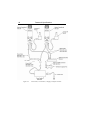
Features & Specifications
Figure 21:
Connections, 1 Controller, 1 Supply
37
38
Features & Specifications
Figure 22:
Connections, 2 Controllers, 1 Supply
Features & Specifications
Figure 23:
Connections, 1 Controller, 1 Supply, Computer Control
39
40
Features & Specifications
Figure 24:
Connections, 2 Controllers, 1 Supply, Computer Control
Features & Specifications
Figure 25:
3.6
41
Connections, 1 Controller, 1 Switchbox, 2 Positioners
Connection to Non-NewStep Components
The NewStep system is primarily intended as a closed system which only
utilizes the components described in this manual.
Other controllers. Use of a non-NewStep controller with NewStep positioners
is strongly discouraged. This because the NSA12 linear actuator and MFA-PP
linear stage provide only one limit signal, and the current and duty cycle must be
strictly controlled to avoid damage.
42
Features & Specifications
CAUTION
There is a high risk of damage to a NewStep positioner with use of a
non-NewStep controller. Such use immediately voids the warranty of
the positioner.
Other positioners. Use of non-NewStep positioners with a NewStep controller
is possible for customers with experience in stepper motor control systems engineering. Newport is not equipped to provide personal support for such applications, but can provide technical information in the form of a Technical Application Note:
DS-04041. Using a NSA 12 with a controller other than the Newport NSC200.
CAUTION
Newport can only guarantee CE compliance of NewStep components
when these are used with other NewStep components, including
cables.
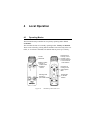
4
Local Operation
4.1
Operating Modes
The NSC200 NewStep controller has two primary operating modes: Local
and Remote.
The controller also has two secondary operating modes: Velocity and Position.
These can be selected by pressing buttons marked V or P or the body of the controller, or via software commands. The default mode at power-up is Velocity.
Tri-color
status LED
V
P
Buttons to select:
• Velocity or
Position mode
• Switchbox
channel
Mounting holes
for bolts to
optical table
Figure 26:
NSC200 top and bottom views
Control knob for:
• Velocity control
• Position control
• Channel selection
• Local or Remote
mode selection
Flat portion of
housing to seat
against optical
table
Reset button
for RS-485
address
44
4.2
Local Operation
Manual User Controls
1. Selection of Remote or Local mode. Press in the control knob to toggle
between Local and Remote. The new selection will only become effective
after any ongoing motion has stopped. In Remote mode (yellow LED), the
controller responds to computer commands only, and the control knob is
disabled. In Local mode (green LED), the control knob is enabled, and computer commands are disabled.
2. Selection of Velocity or Position mode. First press the control knob to
switch from Local to Remote (yellow LED). Then press the left button
(marked V) for Velocity or right button (marked P) for Position. Hold down
the button for 2 seconds. The LED will flash twice to indicate that the mode
was successfully changed. Following the mode change, press the control
knob again to switch back to Local (green LED).
3. Homing the positioner. Press down the control knob for longer than 5 sec.
The currently selected positioner will then move toward the home (or index)
position for that type of positioner. Homing will work whether the NSC200
is in Local or Remote mode.
4. Scanning of switchbox channels. If an NSC200 is connected to a switchbox, it must first learn which switchbox channels are connected and store
this information in non-volatile EEPROM. Simultaneously press down the
V and P buttons for 2 seconds, and the controller will scan all eight channel
positions. The 8 LEDs of the switchbox will light up in sequence. Following
the scan, the LED for each connected channel will be yellow. The LED for
the selected channel will be green if there is no problem or red if there is an
error or problem, such as the a positioner at its limit of travel. Scanning will
work whether the NSC200 is in Local or Remote mode.
5. Selection of switchbox channel. Following the scan, toggle the NSC200
to Local mode. Press the V (left button) to decrement the channel or P (right
button) to increment the channel. The LED associated with the selected
switchbox channel will turn green (no problem) or red (error or problem
encountered).
6. Motion control in Velocity mode. Once the NSC200 is in Local and Velocity modes, simply turn the control knob in the forward or reverse direction,
and let go to stop motion. There are seven (8) jog speed settings for each
direction. As the knob is turned further in either direction, the jog velocity
will increase for that direction. The knob is spring loaded, and the resting
Local Operation
45
position corresponds to zero speed. The 8 jog speed settings are part of the
default setting for each type of positioner, but can be modified using the SV
ASCII command.
7. Motion control in Position mode. Once the NSC200 is in Local and Position modes, turn the control knob to its extreme forward or reverse position.
The controller will then move the positioner up or down by a preset number
of micro-steps. To preset the number of micro-step, connect the NSC200 to
a computer and issue an SP command followed by an SM command. To
enable a feature where holding the knob in its extreme position will cause
repositioning at regular intervals, execute an SH command with bit #2 set
to 1, followed by an SM command.
Resetting RS485 bus address. Use a small diameter rod to press the reset
button on the back of the controller. This will reset the RS485 bus address
of the controller to its factory default setting of zero (0) so that the controller can
be recognized as unitialized by NewStep-Util software. Once a desired RS485
bus address has been entered, the controller can then be digitally addressed in
Remote mode using either NewStep-Util software or ASCII commands.
4.3
Reading the LED Status Lights
4.3.1
LED Indicator on NSC200 Controller
A tri-color LED adjacent to the control knob indicates the controller operating
mode and operating conditions:
LED Status
Yellow
Green
Red
Solid
Remote mode,
not in motion
Local mode,
not in motion
Error condition
Blinking
Remote mode,
in motion
Local mode,
in motion
Firmware
download
4.3.2
LED Indicators on NSC-SB Switchbox
A bank of eight tri-color LEDs on the front panel of the switchbox indicates the
status of each channel:
46
Local Operation
LED Status
Connected & selected
Disconnected & selected
Connected & unselected
Disconnected & unselected
Green
Red
Yellow
Off
Solid
Solid
Solid
Off
5
NewStep-Util Software
5.1
Overview
Newport’s NewStep Utility program, NewStep-Util, provides computer access
to the most commonly used NSC200 controller functions, including changing
controller configuration, monitoring status, and issuing move/jog commands.
This program is distributed on CD ROM with NSC200 controller purchases.
Note that the version of NewStep-Util distributed with the NSC200 is not backward compatible with the version distributed with the predecessor NSC100. It is
however possible to use NSC100’s and NSC200’s on the same RS485 network
provided that their respective software is used.
5.2
RS232 Communications Setup
Cabling. For computer control, an NSC200 controller or NSC-SB switchbox is
connected to the RS232 COM Port of the PC via an RS485-to-RS232 converter,
Model NSC-485-232-I. Please refer to the previous manual section for hookup
diagrams. The converter is normally secured directly to the computer, but a
straight-through serial data cable with a male DB9 connector on one end and a
female DB9 connector on the other end can also be used to connect the converter and PC.
COM Port Setup. 19200 bps, 8 data bits, no parity, 1 stop bit, xON / xOFF
flow control.
Handshake Protocol. Handshaking between the host computer and controller
is automatically provided by NewStep-Util software. The paragraph below is for
background purposes only.
To prevent buffer overflow when data is transferred to the NSC200 input buffer,
a CTS/RTS hardware handshake protocol is implemented. The host computer
controls transmission of characters from the controller by enabling a Request To
Send (RTS) signal once the controller’s Clear To Send (CTS) signal is ready.
Before sending any further characters, the controller waits for a CTS from the
48
NewStep-Util Software
host computer. As soon as its command buffer is full, the controller de-asserts
CTS. Then, as memory becomes available because the controller has read and
executed commands in its buffer, it reasserts the CTS signal to the host
computer.
5.3
Software Installation
The NewStep-Util program allows computer control of most features available
in the NSC200 controller. It is designed to run on a Pentium-class PC with a
minimum of 64 MB of RAM and Windows 98, 2000, NT or XP.
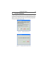
To install NewStep-Util, load the distribution CD and double-click on setup.exe.
The program will give you the option of where to load the files, or you can use
the default directory C:\Program Files\NewStep Controller.
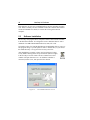
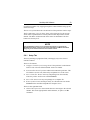
After installation is complete, reboot your PC and open NewStepUtil by double-clicking on the newly created icon (shown to right)
in the NewStep Controller folder. The Set Communication Port
window will open. Enter the Port # to which the controller is
connected, such as Com1, then press the Enter button.
Figure 27:
Set Communication Port Screen
NewStep-Util Software
5.4
49
Controller Initialization
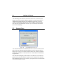
Connect a controller to the specified port. If the program finds that the controller
is uninitialized (controller address equal to zero as shipped from the factory), the
Initialize Controller window (shown below) will open. Type the desired unique
address (1-255) into the Controller Address field, or use the up or down arrows
to increment or decrement, then press OK.
Figure 28:
Figure 29:
Initialize Controller Screen
Initializing Another Controller Screen
50
NewStep-Util Software
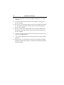
After initializing each controller, the Initialize Controller? screen will open,
asking if you want to initialize another controller. If you do, plug in the next
uninitialized controller and press the YES button. The Initialize Controller
window will open again, allowing you to enter an address for that controller.
Note that only one uninitialized controller may be connected to the network
at a time for initializing.
5.5
Network Scan
Figure 30:
Set Communication Port Screen
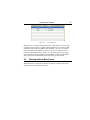
After all controllers have been initialized, the Scan Controller window (shown
above) will open. Enter the maximum address to scan for, then press the Yes
button. The NewStep-Util software will then scan the bus, find any controllers,
and find any switchboxes connected to them. It will also discover and identify
any positioners.
Note that while the highest possible address is 255, the time to scan the bus is
proportional to the actual number of addresses to be scanned. If the check box
at the bottom left of the screen is checked, the program will not scan the bus the
next time the program is started.
NewStep-Util Software
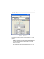
Figure 31:
View all Screen
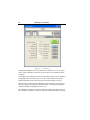
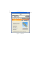
The Main Screen will open following the scan. Click on the View All tab. The
resulting screen will show at a glance which controller #’s are on the bus and
which have an associated switchbox with channel #’s. In case of a controller
with no switchbox, the channel # is always 1. In case of a controller with a
switchbox, the channel # may be from 1 to 8. Also shown is the type of positioner associated with each controller # and channel # (NSA12 or MFA-PP).
The system will associate default values with each type of positioner.
5.6
Working with the Main Screen
The Main Screen, which appears after the bus has been scanned, is the main
working screen of NewStep-Util software.
51
52
NewStep-Util Software
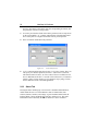
Figure 32:
Setup Screen
Navigation through the screen is by means of five tabs (Move, View all, Setup,
Status, About). With all five tabs, the top 25% of the screen remains the same,
as follows:
The headline at the top shows the name of the channel (NSA12 in this example),
as assigned by the user for this axis in Axis Description under the Setup tab.
Different channels can be selected by name with up and down arrow keys.
The Controller # field shows the bus address of the controller. You can select a
different controller by typing in a different number or by stepping through the
scanned controllers using and down arrow keys.
The Channel # field shows the channel number associated with the controller to
the left. When a switchbox is used, you can select a different channel by typing
NewStep-Util Software
53
in a different number of by stepping through the scanned channels using up and
down arrow keys.
The micro-steps field shows the current location of the positioner in micro-steps.
The five tabs (Move, View all, Setup, Status, About) bring up five sub-screens,
which will be explained below. The Stop Motion button steps motion for that
channel. The Motor ON button turns on the motor for that channel. The Exit
button exits NewStep-Util.
NOTE
Only one NSC200 controller can be communicated with at any given time by
NewStep-Util software. Control as well as the Stop Motion and Motor ON buttons
apply only to the selected controller and controller channel.
5.6.1
Setup Tab
The Setup tab brings up eight data fields, which apply only to the selected
controller channel.
There are five buttons:
1.
Configure Controller for New Stage. Press if the positioner is other than an
NSA12. This will cause different default values to be loaded.
2.
Scan Switchbox. Press if you have added or disconnected a positioner. This
will initiate a new bus scan, followed by an updated View all tab screen.
3.
Save to Controller. Press to enter any setup changes into the controller,
where they will be saved in non-volatile EEPROM.
4.
Save to File. Press to save any setup changes as a computer file.
5.
Restore from File. Press to load previously save file data into non-volatile
EEPROM of the controller and update the computer screen.
There are also eight data fields:
1.
Channel Description is a custom name that a user can assign to the selected
channel. This can be eight printable ASCII character, no spaces. See ID
command.
54
NewStep-Util Software
2.
Velocity is the desired velocity of the channel in full-steps/sec. See VA
command.
3.
Acceleration is the desired acceleration of the channel in full-steps/sec2.
See AC command.
4.
Max Velocity is the maximum allowed velocity of the channel in full-steps/
sec. The software will assign a default value for the specified positioner
type. See VU command.
5.
Max Acceleration is the maximum allowed acceleration in full-steps/sec2.
The software will assign a default value for the specified positioner type.
See AU command.
6.
+ Travel Limit is the positive software travel limit in micro-steps (1/64 of
a full-step). See SR command.
7.
- Travel Limit is the negative software travel limit in micro-steps. See SL
command.
8.
Backlash Value is a compensation value in micro-steps that the controller
will add for each direction change to compensate for mechanical backlash.
See BA command.
NewStep-Util Software
5.6.2
55
Move Tab
Figure 33:
Move Screen
Pressing the Move tab brings up the above window with functions to move the
positioner:
1.
Jog is a bar with 8 positive and 8 negative positions, each of which corresponds to a speed setting. Press on any of the fields, and the positioner will
move at the speed and direction set by that field. There is also a center
position for zero speed.
2.
Move to provides two white fields with absolute positions (Move 1 and
Move 2) in micro-steps. Type in desired positions or press the up or down
56
NewStep-Util Software
arrows to increment or decrement. Press the corresponding Go button, and
the positioner will move to that position.
3.
Increment provides three fields with relative positions in micro-steps. Press
on the corresponding + or – buttons, and positioner will make that relative
move in the positive or negative directions from its present position.
4.
Home is a button which homes the positioner.
Figure 34:
5.
Cycle Utility Screen
Cycle is a button which opens the NewStep Cycle Utility window. Here you
can specify two absolute positions (Position 1 and Position 2) between
which the actuator will move, as well as a Dwell Time in seconds between
moves. Minimum dwell time is 1 second. Click on the Start Cycle button to
initiate cycling. Click on the Stop Cycling button to stop cycling. Click on
the Exit button to return to the main application.
5.6.3
Status Tab
Pressing the Status tab brings up a screen with 11 simulated LED indicators,
which enable the user to view the hardware status of actual LEDs, limit
switches, buttons, encoders, and voltage. A green simulated LED with an H
indicates High, a white simulated LED with an L indicates Low. This same
information is also returned by the PH Get Hardware Status command.
NewStep-Util Software
Figure 35:
5.6.4
Status Screen
About Tab
Pressing the About tab brings up a screen which shows the current versions
of NewStep-Util software and controller firmware as well as Newport contact
information for technical support.
57
58
NewStep-Util Software
Figure 36:
About Screen
6
NewStep ASCII Command Set
6.1
Command Set Introduction
This section describes the supported two-letter ASCII commands that may be
used to configure and operate the NSC200 NewStep controller in Remote mode
(Yellow LED), when the controller is connected to a computer either directly or
via an NSC-SB switchbox. These commands work with LabView, Visual Basic,
C++, or any other computer application that can issue ASCII commands via a
computer COM port. Newport’s NewStep-Util application, described in the previous section of this manual, utilizes these commands.
Note that the ASCII Command Set distributed with the NSC200 is not backward
compatible with the set distributed with the predecessor NSC100. It is however
possible to use NSC100’s and NSC200’s on the same RS485 network provided
that their respective software is used.
6.1.1
LabView Support
Shipped with every NSC200 controller is a CD ROM with .llb drivers that are
compatible with LabView versions 5.0 and above. These are building blocks for
users who want to write their customer applications instead of using NewStepUtil.
6.1.2
Address Field
Since multiple NewStep controllers may be placed on the RS485 Bus or be
connected to an NSC-SB Switchbox, each controller is assigned an address xx
(or controller number) from 0 to 255. By decoding the address field of the
incoming message, the controller can determine if the message is intended for
it. This address xx needs to be prefix to each command. If the address does not
match a specific controller, that controller ignores the message. If the address
is missing, there is no error message, but the address is implied to be 0. If the
address is out of range, i.e., larger than 255, there is no error message, and no
controller will respond.
60
NewStep ASCII Command Set
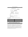
6.1.3
Set or Query Commands
Commands are either Set or Query commands. A Set command changes a setup
parameter or initiates an action. A Query command, which is always terminated
by a question mark, reads back setup or status information. When the controller
responds to a query, it first sends out the received command and then follows
with the requested information. For example, if 234VE? is sent to controller 234,
it may respond with 234VE? 1.0
6.1.4
Saving Settings to Non-Volatile Memory
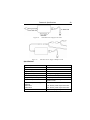
When a setting is changed using a Set command, the new setting is written to
RAM and is implemented immediately. When power is removed and reapplied,
the change is lost unless the setting has been saved to non-volatile memory
using the SM command. Always execute an SM command if you want changed
parameters to be saved.
6.2
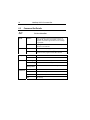
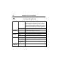
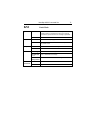
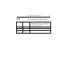
Command Set Summary
Command
Name
Short Description
Set
Command
Query
Command
1.
AC
Acceleration
√
√
2.
AU
Maximum Acceleration
√
√
3.
BA
Backlash Compensation
√
√
4.
BX
Scan Switchbox
√
√
5.
BZ
Restore EEPROM
√
-
6.
DH
Define Home
√
√
7.
ID
Positioner Identification
√
√
8.
JA
Jog
√
√
9.
JS
Jog Scale Factor
√
√
10.
KM
Knob Mode
√
√
11.
MF
Motor OFF
√
-
12.
MO
Motor ON
√
-
13.
MX
Select Switchbox Channel
√
√
NewStep ASCII Command Set
61
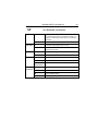
14.
OA
Homing Acceleration
√
√
15.
OH
Homing Speed
√
√
16.
OR
Home
√
√
17.
PA
Absolute Position
√
√
18.
PD
Position Delay
√
√
19.
PH
Hardware Status
-
√
20.
PR
Relative Position
√
√
21.
RS
Reset
√
-
22.
SA
Controller Number
√
-
23.
SH
Set Hardware Configuration
√
√
24.
SL
Negative Software Limit
√
√
25.
SM
Save in Memory
√
-
26.
SP
Knob Position
√
√
27.
SR
Positive Software Limit
√
√
28.
ST
Stop Motion
√
-
29.
SV
Knob Velocities
√
√
30.
TE
Tell Error
-
√
31.
TP
Tell Position
-
√
32.
TS
Controller Status
-
√
33.
VA
Velocity
√
√
34.
VE
Firmware version
-
√
35.
VU
Maximum Velocity
√
√
Table 1
Summary of Commands
62
6.3
NewStep ASCII Command Set
Command Set Details
AC
Syntax
Parameters
Examples
Errors
Related
Commands
Set Acceleration
2
xxACnn
Sets acceleration value nn in full-steps/second for
controller xx. Execution is immediate. If motion is in
progress, command is ignored and an error message
is generated.
xxAC?
Reports current acceleration value nn in full-steps/
2
second for controller xx.
xx
Controller number (integer) from 0 to 255.
nn
Acceleration in full-steps/second (floating number) to
maximum value programmed with AU command.
21AC12.5
Sets acceleration value to 12.5 for controller 21.
21AC?
Reads acceleration value from controller 21.
nn missing
Error 38. Parameter missing.
nn out of range
Error 7. Parameter out of range.
Command
during motion
Error 226. Command not allowed during motion.
AU
Set maximum acceleration or deceleration.
PA
Move to absolute position.
PR
Move to relative position.
VA
Set velocity.
2
NewStep ASCII Command Set
AU
Syntax
Parameters
Examples
Errors
Related
Commands
63
Set Maximum Acceleration
2
xxAUnn
Sets maximum acceleration value nn in full-steps/second
for controller xx. Execution is immediate. If motion is in
progress, command is ignored and an error message is
generated.
xxAU?
Reports current maximum acceleration value.
xx
Controller number (integer) from 0 to 255.
nn
Maximum acceleration value in full-steps/second (floating
number) from 0 to 500.
21AU12.5
Sets maximum acceleration value to 12.5 for controller 21.
21AU?
Reads maximum acceleration value from controller 21.
nn missing
Error 38. Parameter missing.
nn out of range
Error 211. Maximum acceleration exceeded.
Command
during motion
Error 226. Command not allowed during motion.
AC
Set acceleration or deceleration.
PA
Move to absolute position.
PR
Move to relative position.
VA
Set velocity
2
64
NewStep ASCII Command Set
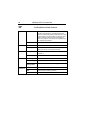
BA
Syntax
Parameters
Examples
Errors
Related
Commands
Set Backlash Compensation
xxBAnn
Sets backlash compensation value nn in micro-steps for
controller nn. For each direction change, controller will
add nn micro-steps to commanded position to compensate for mechanical backlash. There are 64 micro-steps
per full-step. This command is effective only after an OR
(home search) or DH (define home) has been executed.
If motion is in progress, command is ignored and an error
message is generated.
xxBA?
Reports backlash compensation value for controller xx.
xx
Controller number (integer) from 0 to 255.
nn
Backlash compensation value (integer) in micro-steps
from 0 to 512
25BA128
Sets backlash compensation value to 128 for controller
25.
25BA?
Read backlash compensation value from controller 25.
nn missing
Error 38. Parameter missing.
nn out of range
Error 7. Parameter out of range.
Command
during motion
Error 226. Command not allowed during motion.
PA
Move to absolute position.
PR
Move to relative position.
NewStep ASCII Command Set
BX
Syntax
65
Scan Switchbox
xxBX
Causes controller xx connected to an NSC-SB switchbox to
scan channels 1-8 and load a positioner table which
indicates which channels are connected to a load. After the
scan process, the selected positioner is the last found. If
the last selected positioner was not found, the first connected positioner is selected. If no positioner is found, the
selected positioner is set to 0.
xxBX?
Reports which switchbox channels from 1-8 are connected
to a load for controller xx. An xxBX command must have
been executed previously.
Parameters
xx
Controller number (integer) from 0 to 255.
Examples
25BX
Initiates a positioner scan for controller 25.
25BX?
Reports which switchbox channels of controller 25 are
connected to a load. For example, the response 25BX 2,4,5
would indicate that channels 2, 4 and 5 are connected to a
load.
66
NewStep ASCII Command Set
BZ
Restore EEPROM Content to Default
Syntax
xxBZ
Restores all non-volatile EEPROM factory default values
for controller xx.
Parameters
xx
Controller number (integer) from 0 to 255.
Example
25BZ
Restores factory default settings for controller 25.
NewStep ASCII Command Set
DH
Syntax
Parameters
Examples
Errors
Related
Commands
67
Define Home Position
xxDHnn
Defines home position value in micro-steps for controller
xx. If motion is in progress, command is ignored and an
error message is generated.
xxDH?
Reads back home position value in micro-steps for
controller xx.
xx
Controller number (integer) from 0 to 255.
nn
Defined home position value in micro-steps. Default value
is 0. There are 64 micro-steps per full-step.
21DH10
Sets home position value to 10 for controller 21.
21DH?
Reads back home position from controller 21.
nn missing
Error 38 Parameter missing.
Command
during motion
Error 226. Command not allowed during motion.
OA
Set homing acceleration.
OH
Set homing speed.
OR
Search for home.
68
NewStep ASCII Command Set
ID
Syntax
Parameters
Examples
Set Positioner Identification
xxID nn
Assigns a user-defined name to a positioner connected
to controller xx. There needs to be a space after ID. If
multiple positioners are connected to the controller via a
switchbox, the positioner is selected via the MX command.
xxID?
Reads back user-defined positioner name from controller
xx.
xx
Controller number (integer) from 0 to 255.
nn
User-defined positioner name up to 8 ASCII characters
long, such as NSA12-1.
25IDNSA12
Set positioner identification to NSA12 for controller 25.
25ID?
Reads back positioner identification from controller 25.
NewStep ASCII Command Set
JA
Syntax
Parameters
Examples
Errors
Related
Commands
69
Start Jog Motion
xxJAnn
Starts a jog motion with speed setting nn in full-steps/
second (fs/sec) for controller xx. If motion is in progress,
command is ignored and an error message is generated.
xxJA?
Reads back last jog speed setting from controller xx.
xx
Controller number (integer) from 0 to 255.
nn
Jog setting from 0 to ±7 in full-steps/second (fs/sec).
Note: for NSA12, 156.62 fs/sec = 1 mm/sec (max speed).
nn value
Jog Speed
0
0 fs/s
±1
±0.07 fs/s
±2
±0.23 fs/s
±3
±0.78 fs/s
±4
±3.12 fs/s
±5
±15.62 fs/s
±6
±48.87 fs/s
±7
±156.62 fs/s
25JA-5
Starts jog motion at -15.62 fs/sec for controller 25.
25JA?
Reads back value of last jog speed from controller 25.
nn missing
Error 38. Parameter missing.
nn out of
range
Error 7. Parameter out of range.
Motor off
Error 213. Motor not enabled.
Command
during motion
Error 226. Command not allowed during motion.
MO
Motor on.
JS
Set Jos scale factor.
ST
Stop motion.
70
NewStep ASCII Command Set
JS
Syntax
Parameters
Examples
Errors
Related
Commands
Set Jog Scale-up Factor
xxJSAnn
Sets jog scale-up factor nn for controller xx. This is a
multiplier applied to all speed values set by the JA command. It is applied to computer commands, the control
knob, and homing process. By default, it is set to 1 for the
NSA12 and 6 for the MFA-PP. If motion is in progress,
command is ignored and an error message is generated.
xxJS?
Reports jog scale-up factor.
xx
Controller number (integer) from 0 to 255.
nn
Jog scale-up factor (integer) from 0 to 255.
25JS6
Sets Jog scale-up factor to 6 for controller 25.
25JS?
Reads back jog scale-up factor for controller 25.
nn missing
Error 38. Parameter missing.
nn out of range
Error 7. Parameter out of range.
Command
during motion
Error 226. Command not allowed during motion.
JA
Start jog motion.
NewStep ASCII Command Set
KM
Syntax
Parameters
Examples
Errors
Related
Commands
71
Knob Mode
xxKMnn
Sets knob control mode nn to 0 for velocity mode or 1 for
position mode for controller xx. If motion is in progress,
command is ignored and an error message is generated.
xxKM?
Reads back knob control mode for controller xx.
xx
Controller number (integer) from 0 to 255.
nn
Knob control mode. Choices are 0 for velocity mode or 1
for position mode.
21KM0
Sets knob control mode to velocity for controller 21.
21KM?
Reads back knob control mode from controller 21.
nn missing
Error 38. Parameter missing.
nn other than
0 or 1
Error 7. Parameter out of range.
Command
during motion
Error 226. Command not allowed during motion.
SV
Set velocities for knob control.
SP
Set position distance for knob control.
72
NewStep ASCII Command Set
MF
Motor Off
Syntax
xxMF
Turns motor off for controller xx.
Parameter
xx
Controller number (integer) from 0 to 255.
Example
43MF
Turns positioner motor off for controller 43.
Related
Commands
MO
Motor on.
NewStep ASCII Command Set
MO
Motor On
Syntax
xxMO
Turns motor on for controller xx.
Parameter
xx
Controller number (integer) from 0 to 255.
Example
43MO
Turns positioner motor on for controller 43.
Related
Commands
MF
Motor off.
JT
Stop motion.
73
74
NewStep ASCII Command Set
MX
Syntax
Parameters
Examples
Errors
Related
Commands
Select Switchbox Channel
xxMX y
Causes controller xx to command switchbox channel y.
Upon execution, the controller loads settings from its
non-volatile memory for channel y. If there is no switchbox or motion is in progress, command is ignored and
an error message is generated.
xxMX?
Reads back channel number y, as selected by the last
MX command for controller xx.
xx
Controller number (integer) from 0 to 255.
y
Switchbox channel (integer) from 1 to 8.
4MX 8
Selects positioner connected to controller 4 and switchbox channel 8, and loads appropriate settings from its
non-volatile memory.
4MX?
Returns 4MX 8 for the above example, where 4 is the
controller number and 8 is the switchbox channel.
No switchbox in
scan table
Error 6. Invalid command.
Positioner not
in scan table
Error 214. Invalid axis.
y other than
1-8
Error 7. Parameter out of range.
Command
during motion
Error 226. Command not allowed during motion.
BX
Scan Switchbox.
SA
Controller Number.
NewStep ASCII Command Set
OA
Syntax
Parameters
Examples
Errors
75
Homing Acceleration
2
xxOAnn
Sets homing acceleration to nn in full-steps/sec for controller xx. If motion is in progress, command is ignored and
an error message is generated.
xxOA?
Reads back homing acceleration nn in full-steps/sec for
controller xx.
xx
Controller number (integer) from 0 to 255.
nn
Homing acceleration in full-steps/sec (floating number) up
to maximum acceleration specified by AU command.
Default value is 624.00 (maximum acceleration for NSA12).
21OA20.0
Sets homing acceleration to 20.0 full-steps/sec for
controller 21.
21OA?
Reads back homing acceleration in full-steps/sec from
controller 21.
nn missing
Error 38. Parameter missing.
2
2
2
2
nn exceeds
Error 7. Parameter out of range.
limit set by AU
Related
Commands
Command
during motion
Error 226. Command not allowed during motion.
DH
Set home position
OH
Set homing speed.
OR
Search for home.
76
NewStep ASCII Command Set
OH
Syntax
Parameters
Examples
Errors
Related
Commands
Homing Speed
xxOHnn
Sets homing speed nn in full-steps/sec (fs/sec) for controller xx. If motion is in progress, command is ignored
and an error message is generated.
xxOH?
Reads back homing speed nn in full-steps/sec for
controller xx.
xx
Controller number (integer) from 0 to 255.
nn
Homing speed in full-steps/sec (floating number) up to
maximum speed specified by VU command. Default value
is156.00 (maximum speed for NSA12).
21OH125.0
Sets homing speed to 125.0 fs/sec for controller 21.
21OA?
Reads back homing speed in fs/sec from controller 21.
nn missing
Error 38. Parameter missing.
nn exceeds
limit set by VU
Error 7. Parameter out of range.
Command
during motion
Error 226. Command not allowed during motion.
DH
Set home position
OA
Set homing acceleration.
OR
Search for home.
NewStep ASCII Command Set
OR
Syntax
77
Search for Home
xxOR
Starts process of homing positioner to its negative hard
limit. Once positioner is homed, position is set to zero. If
motion is in progress, command is ignored and an error
message is generated.
xxOR?
Returns 1 if positioner has been homed or 0 if it has not
been homed since last power up.
Parameters
xx
Controller number (integer) from 0 to 255.
Examples
35OR
Homes the positioner connected to controller 35.
35OR?
Returns a 1 or 0 depending on whether controller 35 has
been homed or not.
Motor off
Error 213. Motor not enabled.
Command
during motion
Error 226. Command not allowed during motion.
DH
Define home.
OA
Homing acceleration.
OH
Homing speed.
ST
Stop motion.
Errors
Related
Commands
78
NewStep ASCII Command Set
PA
Syntax
Parameters
Examples
Errors
Related
Commands
Move to Absolute Position
xxPAnn
Initiates a move to absolute position nn in micro-steps
for controller xx. When command is received, positioner
executes a trapezoidal trajectory with a predefined
acceleration, dwell speed, and deceleration. If motion
is in progress, command is not accepted and an error
message is generated.
xxPA?
Reports last commanded absolute position in microsteps for controller xx.
xx
Controller number (integer) from 0 to 255.
nn
Absolute position (integer) from -60000 to 120000 in
micro-steps. There are 64 micro-steps per full-step.
25PA1000
Initiates motion to position 1000 for positioner connected
to controller 25.
25PA?
Reads back last commanded absolute position for
controller 25.
nn missing
Error 38. Parameter missing.
nn out of range
Error 7. Parameter out of range.
Motor off
Error 213. Motor not enabled.
Command
during motion
Error 226. Command not allowed during motion.
AC
Set acceleration.
BA
Backlash compensation.
PR
Move to relative position.
ST
Stop motion.
VA
Set velocity.
NewStep ASCII Command Set
PD
Syntax
Parameters
Examples
Related
Commands
79
Position Delay in Knob Control
xxPDnn
Sets delay between moves to nn milliseconds for
controller xx.
xxPD?
Reads delay value nn in milliseconds for controller xx.
xx
Controller number (integer) from 0 to 255.
nn
Delay value between moves in milliseconds. Default
value is 100 ms.
21PD50
Sets delay between moves to 50 ms for controller 21.
21PD?
Reads delay setting in milliseconds from controller 21.
nn missing
Error 38. Parameter missing.
KM
Set knob mode
SV
Set velocities for knob control.
SP
Set position distance for knob control.
80
NewStep ASCII Command Set
PH
Syntax
Get Hardware Status
xxPH?
Returns 24 status bits (3 bytes) from controller. These
are reported as a decimal number, which needs to be
converted to binary.
Bit#
0
1
2-7
8
9
10
11
12
13
14
15
16
17
18
19
20
21-23
Status for bit value 1
(status is opposite for bit value 0)
Green LED on
Red LED on
N/A
Negative travel limit reached
Positive travel limit reached
N/A
Device reset button not pressed
Button A not pressed
Button B not pressed
Jog knob switch not pressed
Low voltage not detected
Encoder A signal high
Encoder B signal high
Driver line 1 no fault.
Driver enabled
Driver line 2 no fault
N/A
Parameters
xx
Controller number (integer) from 0 to 255.
Example
14PH?
Returns 24 status bits from controller 14 as a decimal
number, such as 147843. One way to convert this to
binary is to use the Windows scientific calculator. Click
on Start > Programs > Accessories > Calculator > View >
Scientific > Dec (decimal). Copy and paste in the decimal
number, then click on Bin (binary) to display the binary
equivalent. The binary bits 0-24 are read from right to left.
NewStep ASCII Command Set
PR
Syntax
Parameters
Examples
Errors
Related
Commands
81
Move to Relative Position
xxPRnn
Initiates a move to relative position nn in micro-steps
for controller xx. When command is received, positioner
executes a trapezoidal trajectory with a predefined
acceleration, dwell speed, and deceleration. If motion
is in progress, command is not accepted and an error
message is generated.
xxPR?
Reports last commanded relative position in micro-steps
for controller xx.
xx
Controller number (integer) from 0 to 255.
nn
Relative position (integer) from -60000 to 120000 in
micro-steps. There are 64 micro-steps per full-step.
25PR1000
Initiates relative move of 1000 micro-steps for positioner
connected to controller 25.
25PR?
Reads back last commanded relative position for
controller 25.
nn missing
Error 38. Parameter missing.
nn out of range
Error 7. Parameter out of range.
Motor off
Error 213. Motor not enabled.
Command
during motion
Error 226. Command not allowed during motion.
AC
Set acceleration.
BA
Backlash compensation.
PA
Move to absolute position.
ST
Stop motion.
VA
Set velocity.
82
NewStep ASCII Command Set
RS
Reset Controller
Syntax
xxRS
Soft-resets processor in controller xx.
Parameter
xx
Controller number (integer) from 0 to 255.
Example
31RS
Soft-resets controller 31.
NewStep ASCII Command Set
SA
83
Set Controller Address
Syntax
xxSAnn
Changes current controller address xx to new address
nn.
Parameters
xx
Current controller address (integer) from 0 to 255.
nn
New controller address (integer) from 0 to 255.
Example
0SA14
Changes controller address from 0 to 14.
Errors
nn missing
No error message returned. nn is set to 0.
nn out of range
Error 7. Parameter out of range.
84
NewStep ASCII Command Set
SH
Syntax
Parameters
Set Hardware Configuration
xxSHnn
Sets eight binary bits to specify the hardware configuration
of the positioner connected to controller xx. nn is entered
as a decimal number, which is automatically converted to
binary by the controller. The factory default value of nn is
decimal zero, which sets all eight bits to zero.
xxSH?
Reads back eight hardware configuration bits nn for positioner connected to controller xx. The data is returned as
a decimal number, to be converted to binary by the user.
xx
Controller number (integer) from 0 to 255.
nn
Bit# Val. Description
0
0
Enable hardware limit checking.
1
Disable hardware limit checking.
1
0
Reserved. Always set to zero.
2
0
Do not command a new relative move if in
position mode and knob is turned all the way.
1
Command a new relative move if in position
mode and knob is turned all the way.
0
Enable local access to switching between
velocity and position modes.
1
Disable local access to switching between
velocity and position modes.
0
Clockwise turn results in positive motion.
1
Clockwise turn results in negative motion.
0
Enable local switchbox scan.
3
4
5
6
7
1
Disable local switchbox scan.
0
Enable home search process (local/remote)
1
Disable home search process (local/remote)
0
Enable software travel limit checking.
1
Disable software travel limit checking.
NewStep ASCII Command Set
Examples
Errors
85
12SH00
Enables hardware limit checking, etc., for controller 12.
One way to convert the desired binary number to decimal is
to use the Windows scientific calculator. Click on Start >
Programs > Accessories > Calculator > View > Scientific >
Bin (binary). Enter the desired binary number, then click on
Dec (decimal) to display the decimal number to be entered
as nn. The binary bits 0-7 are read from right to left.
12SH?
Reads back hardware configuration from controller 12.
nn missing
No error message. nn and all bit values are set to 0.
nn out of
range
No error message. Controller only looks at first 8 bits
following conversion to binary.
86
NewStep ASCII Command Set
SL
Syntax
Parameters
Examples
Errors
Related
Commands
Set Left Travel Limit
xxSLnn
Sets value of negative software limit, or extreme left
allowed range of travel. This value should be less than
the positive software limit. If motion is in progress,
command is not accepted and an error message is
generated.
xxSL?
Reports value of negative (left) software limit.
xx
Controller number (integer) from 0 to 255.
nn
Negative software limit (integer) from -60000 to 120000
micro-steps. There are 64 micro-steps per full-step.
72SL-100
Sets negative software limit to -100 for controller 72.
72SL?
Reads back negative software limit from controller 72.
nn missing
Error 38. Parameter missing.
nn out of range
Error 7. Parameter out of range.
Command
during motion
Error 226. Command not allowed during motion.
JA
Jog.
PA
Move to absolute position.
PR
Move to relative position.
SR
Positive software limit.
NewStep ASCII Command Set
SM
87
Save Settings to Non-Volatile Memory
Syntax
xxSM
Saves controller configuration settings from RAM to
non-volatile EEPROM memory. This command should
be issued after modifying settings so that these are not
lost when controller is powered off.
Parameters
xx
Controller number (integer) from 0 to 255.
Examples
61SM
Saves changes for controller 61 to non-volatile memory.
Related
commands
AC, AU, SL, SR,
VA, VU, etc…
All commands that change a setting.
88
NewStep ASCII Command Set
SP
Syntax
Parameters
Examples
Errors
Related
Commands
Set Position for Knob Control
xxSPnn
Sets an absolute or relative distance nn in micro-steps
that will be commanded by controller xx when knob
control is configured for position mode and knob is at its
extreme position. The sign (positive or negative) of this
distance will be the same as for the knob rotation. If
motion is in progress, command is not accepted and an
error message is generated.
xxSP?
Reads back knob control distance for controller xx.
xx
Controller number (integer) from 0 to 255.
nn
Knob control distance in micro-steps. Default value is
2765. There are 64 micro-steps per full-step.
12SP1000
Sets knob control distance to 1000 micro-steps for
controller 12.
12SV?
Reads back knob control distance from controller 12.
nn missing
Error 38. Parameter missing.
nn out of range
Error 7. Parameter out of range.
Command
during motion
Error 226. Command not allowed during motion.
PD
Position delay.
KM
Set knob mode to velocity or position.
SH
Set hardware configuration.
NewStep ASCII Command Set
SR
Syntax
Parameters
Examples
Errors
Related
Commands
89
Set Right Travel Limit
xxSRnn
Sets value of positive software limit, or extreme right
range of travel. This value should be larger than negative software limit. If motion is in progress, command is
not accepted and an error message is generated.
xxSR?
Reports value of positive (right) software limit.
xx
Controller number (integer) from 0 to 255.
nn
Positive software limit (integer) from -60000 to 120000
micro-steps. There are 64 micro-steps per full-step.
72SR3000
Sets positive software limit to 3000 for controller 72.
72SR?
Read back positive software limit from controller 72.
nn missing
Error 38. Parameter missing.
nn out of range
Error 7. Parameter out of range.
Command
during motion
Error 226. Command not allowed during motion.
JA
Jog.
PA
Move to absolute position.
PR
Move to relative position.
SR
Positive software limit.
90
NewStep ASCII Command Set
ST
Stop Motion
Syntax
xxST
Stops motion in progress using deceleration rate
programmed with AC (set deceleration) command for
controller xx.
Parameter
xx
Controller number (integer) from 0 to 255.
Example
41ST
Stops positioner motion for controller 43.
Related
Commands
MO
Motor on.
AC
Set acceleration.
NewStep ASCII Command Set
SV
Syntax
Parameters
Examples
Related
Commands
91
Set Velocities For Knob Control
xxSVn1,n2,n3,
n4,n5,n6,n7,n8
Defines eight (8) velocity settings in full-steps/sec that
controller xx will use when knob control is configured
for velocity mode. A space is optional after each
comma.
xxSV?
Reads back knob velocity settings for controller xx.
xx
Controller number (integer) from 0 to 255.
n1,n2,n3,n4,n5
n6,n7,n8
Eight numbers (floating point) for velocity settings 1-8
in full-steps/sec. Default settings (selected for NSA12)
are the following:
n1
0.00
n2
0.07
n3
0.23
n4
0.78
n5
3.12
n6
15.62
n7
46.87
n8
156.62
12SV0.00,0.07,
Sets eight knob velocity settings for controller 12. The
0.23,0.78,3.12,
values shown are the above default values.
15.62,46.87,156.62
12SV?
Reads back eight knob velocity settings from controller
12.
n1-n8 missing
No error message. All missing values are set to 0.
KM
Set knob mode to velocity or position.
92
NewStep ASCII Command Set
TE
Syntax
Read Error Code
xxTEnn?
Reads error code from controller xx.
Description
No errors
Driver fault (open load)
Driver Fault (thermal shut down)
Driver fault (short)
Invalid command
Parameter Out of Range
No Motor connected
Brown-out
Command parameter missing
Positive hardware limit detected
Negative hardware limit detected
Positive software limit detected
Negative software limit detected
Max velocity exceeded
Max acceleration exceeded
Motor not enabled
Switch to invalid axis
Homing aborted
Parameter change not allowed during motion
Parameters xx
Controller number (integer) from 0 to 255.
Example
Returns error code from controller 43.
23TE?
Error Code
0
1
2
3
6
7
8
10
38
24
25
26
27
210
211
213
214
220
226
NewStep ASCII Command Set
TP
93
Read Position
Syntax
xxTPnn?
Returns position in micro-steps of positioner connected
controller xx and switchbox channel nn. The controller
operates in “open loop” fashion and returns a calculated
value of position. This may be the calculated position
during a very slow motion, or the latest executed commanded position. There are 64 micro-steps per full-step.
Parameters
xx
Controller number (integer) from 0 to 255.
nn
Channel 1-8 of a switchbox connected to controller xx,
if applicable. This term is not needed if there is no
switchbox. If nn is omitted, the position is returned for
the latest channel associated with controller xx.
25TP3?
Returns position value of positioner connected to switchbox channel 3 of controller 25.
25TP?
Returns position value of positioner associated with
controller 25.
JA
Jog.
PA
Move to absolute position.
PR
Move to relative position.
Examples
Related
Commands
94
NewStep ASCII Command Set
TS
Syntax
Controller Status
xxTS?
Returns a status number for controller xx:
Motor on, motion not in progress
Motor on, motion in progress
Motor off, motion not in progress
Parameter
xx
Controller number (integer) from 0 to 255.
Example
25TS?
Returns status number for controller 25.
Related
Commands
MF
Motor off.
MO
Motor on.
TE
Tell error.
TP
Tell position.
81
80
64
NewStep ASCII Command Set
VA
Syntax
Parameters
Examples
Errors
Related
Commands
95
Set Velocity
xxVAnn
Sets velocity value in full-steps/sec (fs/sec) for controller
xx. If motion is in progress, command is not accepted. If
motion is in progress, command is ignored and an error
message is generated.
xxVA?
Reports velocity value in full-steps/sec for controller xx.
xx
Controller number (integer) from 0 to 255.
nn
0 to maximum value (floating point) in full-steps/sec up
to the maximum programmed with VU command. For
example, to set the velocity of an NSA12 actuator to 0.5
mm sec, you would need to program nn to 0.5 mm/sec
x 1 full-step/6.4 µm = 78.1 full-steps/sec.
17VA26.6
Sets velocity of controller 17 to 26.6 full-steps/sec.
17VA?
Reads back velocity in full-steps/sec from controller 17.
nn missing
Error 38. Parameter missing.
nn out of range
Error 210. Maximum velocity exceeded.
Command
during motion
Error 226. Command not allowed during motion.
AC
Set acceleration.
AU
Set maximum acceleration.
VU
Set maximum velocity.
96
NewStep ASCII Command Set
VE
Read Controller Firmware Version
Syntax
xxVE?
Returns firmware version in Major.Minor_NSC200
format.
Parameter
xx
Controller number (integer) from 0 to 255.
Example
38VE?
Returns firmware version of controller 38, such as
3.4_NSC200, where 3 is the major and 4 is the minor
firmware revision.
NewStep ASCII Command Set
VU
Syntax
Parameters
Examples
Errors
Related
Commands
97
Set Maximum Velocity
xxVUnn
Sets maximum value of velocity in full-steps/sec (fs/sec)
for controller xx. If motion is in progress, command is not
accepted and an error message is generated.
xxVU?
Reports maximum value of velocity in full-steps/sec
(fs/sec) for controller xx.
xx
Controller number (integer) from 0 to 255.
nn
Maximum value (floating point) of velocity in full-steps/sec.
17VU156.2
Sets maximum velocity of controller 17 to 156.2 full-steps/
sec. This example is the maximum speed of the NSA12:
1 mm/sec x 1 full-step/6.4 µm = 156.2 full-steps/sec.
17VA?
Reads back maximum velocity in full-steps/sec from
controller 17.
nn missing
Error 38. Parameter missing.
nn out of range
Error 7. Parameter out of range.
Command
during motion
Error 226. Command not allowed during motion.
VA
Set velocity.
AC
Set acceleration.
AU
Set maximum acceleration.
7
Maintenance & Service
CAUTION
There are no user serviceable parts inside NewStep components.
Work performed by persons not authorized by Newport Corporation
will void the warranty.
7.1
Enclosure Cleaning
The NewStep Actuator and Motion Controller should only be cleaned with a
soapy water solution. Do not use an acetone or alcohol solution, as this will
damage the finish of the enclosure.
7.2
Technical Support
This section contains information regarding factory service for NewStep Actuators and Controllers. The user should not attempt any maintenance or service of
the equipment. Any problem that cannot be resolved should be referred to
Newport Corporation.
Telephone
1-800-222-6440
Fax
1-949-253-1479
Address
Newport Corporation Service Department
1791 Deere Ave., Irvine, CA 92606
Email
[email protected] or [email protected]
Web Page
URL
http://www.newport.com/Support/Technical_Help/
http://www.newport.com/Support/Service_and_Returns/
Contact Newport to obtain information about factory service. Telephone
contacts number(s) are provided on a Service Form. Please have the following
information available:
100
Maintenance & Service
• Equipment model number (NSC200, NSA1, MFA-PP, NSC-SB).
• Equipment Serial Number
• Problem Description (document this by using the Service Form)
If the instrument is to be returned for repair, the user will be given a Return
Authorization Number that needs to be referenced in their shipping documentation. Complete a copy of the Service Form shown below and fax it to Newport
at the number indicated.
Maintenance & Service
7.3
101
Service Form
Newport Corporation
USA Office: 800-222-6440
FAX: 949-253-1479
Name ___________________Return Authorization _____________________
(Please obtain RA# prior to return of item)
Company ________________________________________________________
(Please obtain RA # prior to return of item)
Address ________________________________ Date ____________________
Country _______________________ Phone Number _____________________
P.O. Number ___________________ FAX Number ______________________
Item(s) Being Returned:
Model # _______________________ Serial # ___________________________
Description ______________________________________________________
Reason for return of goods (please list any specific problems):
Newport Corporation
Worldwide Headquarters
1791 Deere Avenue
Irvine, CA 92606
(In U.S.): 800-222-6440
Tel: 949-863-3144
Fax: 949-253-1680
Internet: www.newport.com
[email protected]
Visit Newport Online at: www.newport.com