1
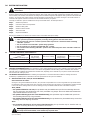
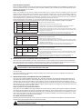
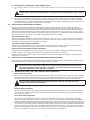
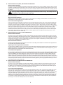
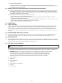
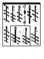
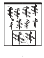
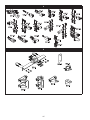
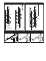
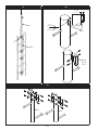
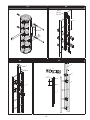
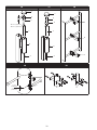
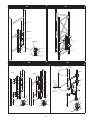
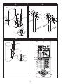
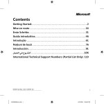
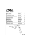
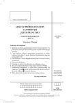
INSTALLATION INSTRUCTIONS
1
LAD-SAF™
Flexible Cable Ladder
Safety Systems
2
The Ultimate in Fall Protection
3
â
á
x1
x4
6
141 kg/
310 lbs
7
CE TYPE TEST
BSI (0086)
Kitemark Court
Davy Ave, Knowlhill
Milton Keynes
MK5 8PP, UK 4
CE
PRODUCTION
QUALITY
CONTROL
BSI (0086)
Kitemark Court
Davy Ave, Knowlhill
Milton Keynes
MK5 8PP, UK 5
I S O
9001
ANSI A14.3
Certificate No. FM 39709
prEN 353-1:2012
CSA Z259.2.5
1
A
B
C
D
E
FORM NO: 5902228
REV: Q
© Copyright 2009, DB Industries, Inc.
EN
FORWARD
This instruction manual describes the installation of the Lad-Saf™ Flexible Cable Ladder Safety Systems. It should be used as
part of an employee training program as required by OSHA, ANSI, CSA, and CE, and must be kept with the equipment.
•To avoid serious injury or death follow the safety information in these instructions.
•Installers must read and follow the manufacturer’s instructions for safety equipment used with this
system.
•Proper fall protection must be used while installing this system.
If you have questions on the installation or suitability of this equipment for your application, contact
DBI-SALA.
GLOSSARY REFERENCES
Numbered Glossary References on the front cover of this instruction reference the following items:
1
Installation Instructions
2
Lad-Saf™ Flexible Cable Ladder Safety Systems
3
Standards
4
Number of notified body that performed CE Test.
5
Number of notified body checking the manufacture of this PPE.
6
Maximum number of users.
7
Maximum user weight is 141 kg (310 lbs) including tools, other equipment and clothing.
Lad-Saf™ Flexible Cable Ladder Safety System Components, Figure 1:
A
Top Bracket
B
Cable
C
Cable Guide
D
i-Safe RFID Tag
E
Bottom Bracket
Part Lists And Part References
The parts that can comprise a typical Lad-Saf™ Ladder Safety System are listed in the Parts List Table in this manual. Some
items may have multiple part options and part numbers. The “Item” column on the left side of each part list is associated with
one or more part numbers found in the columns to right (for example: TB-1, BB-5, etc.) that can be used for installation. The
installation situation will determine which parts must be used.
2
1.0APPLICATIONS
1.1PURPOSE: When used in combination with the Lad-Saf™ Detachable Cable Sleeve (sold separately), the Lad-Saf™
Flexible Cable Ladder Safety System (Figure 1) is designed to protect a worker in the event of a fall while climbing fixed
ladders or similar climbing structures. LAD-SAF™ systems are intended to be installed on fixed ladders or ladder like
climbing surfaces that are part of a structure (e.g., water tank ladders, mono poles [wood, steel, or concrete] buildings,
manways, antenna structures and towers).
1.2LIMITATIONS: LAD-SAF™ systems are not intended to be installed on portable ladders. These systems are designed
for use on ladders that are generally vertical. The ladder safety system must not exceed a maximum angle of 15° from
vertical. The following application limitations must be considered before installing the LAD-SAF™ system.
A. LADDER STRUCTURE: The ladder structure to which the system is installed must be capable of withstanding the
loads applied by the system in the event of a fall (see Section 2.2).
B. SYSTEM CAPACITY: The number of users allowed on the system at one time varies depending on the type of
system and installation. Generally, system capacities range from one to four users. See sections 2.0 and 3.0 for more
information on capacity limitations. System capacities are based on a maximum user weight, including tools and
clothing, of 310 lbs (140.6 kg).
C. ENVIRONMENTAL HAZARDS: Use of this equipment in areas with environmental hazards may require that
additional precautions be taken to reduce the possibility of injury to the user or damage to the equipment. (e.g., high
heat caused by welding or metal cutting, caustic chemicals, seawater, high voltage power lines, explosive or toxic
gases, moving machinery, sharp edges).
D.TRAINING: This equipment is intended to be installed by persons who have been trained in its correct application.
1.3
Refer to applicable local, and national requirements governing this equipment for more information on ladder safety
systems and associated components, including OSHA 1910.27.
2.0 SYSTEM REQUIREMENTS
2.1
COMPATIBILITY OF COMPONENTS AND SUBSYSTEMS: This equipment is designed for use with DBI-SALA approved
components and subsystems. The use of non-approved components and subsystems (e.g., harnesses, lanyards, sleeves,
etc.) may jeopardize compatibility of equipment, and could affect the safety and reliability of the complete system. If you
have questions on the installation or suitability of this equipment for your application, contact DBI-SALA.
2.2
LOAD REQUIREMENTS FOR STRUCTURE AND BRACKET CONNECTIONS: The climbing structure to which the
LAD-SAF™ system is installed must be capable of supporting the loads imposed by the system. For calculation purposes
the required bracket load may be assumed to be distributed evenly between the number of rung attachments. For
example, the TB-3 top bracket (Figure 2) is supplied with three rung connections. The load required for each rung for a
single user system is 1,125 lbs (5.0 kN) per rung (3,375 lbs [15.0 kN]/3).
A. TOP BRACKET: (See Figure 2 and TB Items Part List) The top bracket connection loads include system pretension
and forces associated with arresting a fall. Load requirements for the top bracket vary depending on the number of
users allowed on the system at one time, top bracket model, and type of connection to the structure.
1. The following top brackets allow up to four users on the system at one time:
Item Numbers; TB-2, TB-3, TB-4, TB-6, TB-7, TB-10 and Part Numbers; 6116048, 6116050, 6116051, 6116052,
TB-1, 6116055, 6116057, 6116059, TB-5, 6116282, 6116286, 6116290, 6116291, 6116292, 6116293, 6116294,
6116295, 6116296.
Note: Other installation requirements may limit the number of users allowed on a system. See section 3.0.
Top Bracket Connection Loads:
• One user on the system: 3,375 lbs (15.0 kN)
• Two users on the system: 4,350 lbs (19.3 kN)
• Three users on the system: 5,325 lbs (23.7 kN)
• Four users on the system: 6,300 lbs (28.0 kN)
Exception: TB-1 top bracket is designed for use with 6116336 or 6116337 grab bar extension. When the grab bar is
used as a connection for a personal fall arrest system the bracket connection must support a minimum of 5,000 lbs
(22.2 kN)., or 3,600 lbs (16.0 kN) for a certified anchorage. See ANSI Z359.1 and OSHA regulations.
2. These top brackets allow one user only:
Item Numbers; TB-8, TB-9, TB-11 and Part Numbers 6116074, 6116325, 6116324 and 6116328.
Exception: TB-9 (6116074) allows two users.
Top Bracket Connection Loads:
• One user on the system: 3,375 lbs (15.0 kN)
• Two users on the system: 4,350 lbs (19.3 kN)
B. BOTTOM BRACKET: The bottom bracket connection must be capable of supporting a system pretension load of
750 lbs (3.3 kN) in the direction of loading.
3
3.0 SYSTEM INSTALLATION
Improper installation procedures could result in serious injury or death. Read and follow all
instructions.
3.1
LAD-SAF™ systems are designed for easy installation onto a variety of fixed ladder structures. To begin the installation you need to
know the model numbers of the top and bottom brackets, cable guides, and type of cable (galvanized or stainless steel). Figures 2, 3,
4 and 5 identify most models. Some brackets are designed to be installed using stand-off supports which go between the bracket and
structure. You need to know model numbers of stand-off supports if included with your system. See Figure 5 for model numbers of
most stand-off supports. Follow the instructions for the models included in your system.
Generally, the LAD-SAF™ system is installed from the top of the ladder down. The basic procedure is:
Step 1.
Install the top bracket
Step 2.
Connect the cable to the top bracket
Step 3.
Install the cable guides
Step 4.
Install the bottom bracket
Step 5.
Tension the cable
Step 6.
Inspect the installation
Planning the installation can minimize the amount of time on the ladder and improve safety.
• Use proper safety procedures when installing LAD-SAF™ systems.
• Wear personal protective equipment, including safety glasses and steel-toed shoes.
• Use personal fall arrest or restraint systems when exposed to a fall hazard while installing
LAD-SAF™ systems.
• Do not connect to the LAD-SAF™ system being installed.
• Do not connect to a partially installed LAD-SAF™ system.
• Use caution when installing LAD-SAF™ systems near electrical power lines. LAD-SAF™ cables are
conductive.
3.2
SYSTEM COMPONENT COMPATIBILITY:
Stainless Cable
with Stainless
Swage Fitting
Stainless Cable
with Carrier Clamp
Galvanized Cable
with Stainless
Swage Fitting
Galvanized Cable
with Carrier Clamp
Stainless
Y
N
N
N
Galvanized
O
N
Y
Y
Bracket Type
Cable and Fitting Type
Y = recommended component combination.
O = optional.
N = not recommended
Do not use carrier clamps with stainless steel cables.
3.3
WELDING RECOMMENDATIONS: Some installations require welding brackets to the structure. DBI-SALA recommends that welding
be completed by a certified professional welder in accordance with applicable national welding codes or standards. Base and filler
materials must be compatible with galvanized or stainless steel, depending on the materials of your system. Protect finished welds
from corrosion with coating or paint.
3.4
TOP BRACKET INSTALLATION: Before installing the top bracket it is recommended that the ladder or climbing structure be
evaluated by a qualified person to determine if the load requirements for the system are satisfied.
A. INSTALLATION OF TB-2, TB-3, TB-10 TOP BRACKETS:
Direct Connection to Ladder:
See Figure 6 for typical installations of the TB-2, TB-3, and TB-10 top brackets onto a round rung ladder. The top bracket should
be positioned to allow users safe access when connecting or disconnecting from the system. The top bracket is typically mounted
in the center of the climbing surface for ease of climbing, but may be located towards the side of the ladder if required.
TB-3, TB-10:
•
For systems limited to one user, the top bracket may be installed with up to four feet extending above the
top rung connection. This will allow the use of only two ladder rung clamps. Ensure the ladder will withstand the
required loads between the two rungs.
•
For systems allowing up to two users simultaneously, the top bracket may be installed with up to three
feet extending above the top rung connection.
•
For systems allowing up to four users simultaneously, the top bracket may be installed with up to two feet
extending above the top rung connection.
TB-2:
•
For systems allowing up to four users simultaneously, the top bracket may be installed with up
to five feet extending above the top bracasket connection.
One rung clamp (two for the TB-10 bracket) is designed to bolt through the bracket and onto the rung.
This clamp must not be omitted, or the bracket may slip under load.
Install rung clamps using the hardware provided. Do not substitute other fasteners. Torque fasteners to 20-25 ft-lbs
(27.1-33.9 N-m).
4
Stand-off Support Connection:
Figure 7 shows the installation of the TB-3 top bracket using a horizontal stand-off bracket. These installations are limited to one
user on the system at a time. Use hex bolts in place of U‑bolts to attach the TB-3 top bracket to the horizontal stand-off. Torque
fasteners to 20-25 ft-lbs (27.1-33.9 N-m).
Ladder Rung Support:
Ladder rung supports can be used to reinforce hollow ladder rungs to reduce crushing or collapsing of the rung due to
tightening of the Ladder Safety System Clamps, and to generally strengthen the rung. The Rung Support must have
sufficient length extending on either side of the Ladder Side Rails to install Rung Support fasteners. Install ladder rung
support at each LAD-SAF™ component connection point. The ladder and its connection to the structure must be evaluated
by a qualified person to determine if the load requirements for the system are met.
Ladder Rung Supports are available in various shapes and lengths. For best results, select a Ladder Rung Support
size that will fit closely with the inside dimensions of the rung. See Figure 8 for examples of ladder rung supports.
Ø
R
6100187
1 in (2.5 cm)
22 in (56 cm)
6100188
1 in (2.5 cm)
26 in (66 cm)
6100189
1 in (2.5 cm)
30 in (76 cm)
Materials
Aluminum Bar, Stainless Steel
Fasteners
C, Figure 8
B, Figure 8
A, Figure 8
Model
Install at each point indicated below:
Ø
R
6100151
1 in (2.5 cm)
17 in (43 cm)
Materials
Aluminum Bar, Stainless Steel
Fasteners
Model
Install at each point indicated below:
H
W
R
6100186
.59 in
(2.5 cm)
1 in
(2.5 cm)
19 in
(48 cm)
Materials
Aluminum Bar, Stainless Steel
Fasteners
Model
1. Slide the Rung Support through the open rung.
2. Slide Washers over each end of the Rung Support and secure with Nuts.
Tighten Nuts until Washer’s are flush against the Ladder Rail.
3. Insert Cotter Pins through the holes in each end of the Rung Support. Cotter
Pins should inserted from the top of the Rung Support to prevent them from
dropping out of the holes.
4. Separate and bend the Cotter Pin Legs to ensure Cotter Pins stay in the
holes and the Rung Supports can not slide out of the Ladder Rung.
1. Slide the Rung Support through the open rung.
2. Insert Cotter Pins through the holes in each end of the Rung Support. Cotter
Pins should inserted from the top of the Rung Support to prevent them from
dropping out of the holes.
3. Separate and bend the Cotter Pin Legs to ensure Cotter Pins stay in the
holes and the Rung Supports can not slide out of the Ladder Rung.
Install at each point indicated below:
1. Slide the Rung Support through the open rung.
2. Insert Cotter Pins through the holes in each end of the Rung Support. Cotter
Pins should inserted from the top of the Rung Support to prevent them from
dropping out of the holes.
3. Separate and bend the Cotter Pin Legs to ensure Cotter Pins stay in the
holes and the Rung Supports can not slide out of the Ladder Rung.
B. INSTALLATION OF TB-1 TOP BRACKET AND 6116336 GRAB BAR:
See Figure 9 for a typical installation of the TB-1 top bracket onto a round rung ladder. The top bracket should be positioned to
allow users safe access when connecting or disconnecting from the system. The top bracket is typically mounted in the center of
the climbing surface for ease of climbing, but may be located towards the side of the ladder if required.
The top rung clamp bolts through a plate that is welded onto the bracket. This rung clamp must
not be omitted, or the bracket may slip under load.
Install rung clamps using the hardware provided. Do not substitute other fasteners. Torque fasteners to 20‑25 ft.-lbs
(27.1-33.9 N-m).
The 6116336 grab bar (A) is installed by sliding the grab bar into the square tube of the TB-1 top bracket and installing the
detent pin (C) into the grab bar.
C. INSTALLATION OF TB-4, TB-6, AND TB-7 BOLT-ON TOP BRACKETS:
See Figure 10 for a typical installation of the TB-4, TB-6, and TB-7 top brackets. The top bracket should be positioned to allow
users safe access when connecting or disconnecting from the system. The top bracket is typically mounted in the center of the
climbing surface, directly above the ladder, for ease of climbing, but may be located towards the side of the ladder, 12 inches
(30.5 cm) maximum from center, if required. The top brackets are to be connected to the structure with a DBI-SALA (model SO-2
stand-off in Figure 10) or customer supplied stand-off support. Stand-off supports must support the loads specified in section 2.2,
and must be compatible with the LAD-SAF™ system.
Angle Leg and Round Leg Stand-off Installation:
See Figure 11 for the installation of the angle (example: SO-4) and round leg (example: SO-5) stand-off supports. Install standoff supports using the hardware provided. Do not substitute other fasteners. Torque 3/8-inch fasteners to 20-25 ft-lbs (27.1-33.9
N-m). Install the top bracket to the stand-off support using the 1/2-inch fasteners provided. Torque 1/2-inch fasteners to 40-45
ft-lbs (54-61 N-m). Note: For the TB-6 stand-off, fasteners are not supplied. DBI-SALA recommends using lock washers, double
nuts, or other methods to ensure fasteners will not loosen.
SO-2 Weld-on Stand-off Installation:
Install the SO-2 stand-off support as shown in Figure 10. See section 3.3 for welding recommendations. The stand-off must be
perpendicular to the pole surface and in-line with the carrier cable.
Installations that use the angle leg or round leg stand-off support brackets are limited to one
user on the system at a time.
5
D. INSTALLATION OF TB-5 WOOD POLE TOP BRACKET:
See Figure 12 for a typical installation of the TB-5 top bracket onto a wooden pole. The top bracket should be positioned to allow
users safe access when connecting or disconnecting from the system. The top bracket is typically mounted in the center of the
climbing surface for ease of climbing, but may be located towards the side of the ladder if required. Use 1/2-inch fasteners (not
provided) to attach the top bracket to the pole. Fasteners should extend through the pole when possible. DBI-SALA recommends
using lock washers, double nuts, or other methods to ensure fasteners will not loosen.
E. INSTALLATION OF TB-9, TB-13, AND TB-14 TOP BRACKETS:
See figure 13 for a typical installation of TB-9, TB-13, and TB-14 top brackets onto a ladder. Some brackets utilize rung
spacers while others do not (see Figure 2). The top bracket should be positioned to allow users safe access when connecting or
disconnecting from the system. The top bracket is typically mounted in the center of the climbing surface for ease of climbing, but
may be located towards the side of the ladder if required.
•
For systems limited to one user, the top bracket may be installed with up to 4 ft. (1.2 m) extending above the
top rung connection. This will allow the use of only two ladder rung clamps. Ensure the ladder will withstand the
required loads between the two rungs.
•
For systems allowing up to two users simultaneously, the top bracket may be installed with up to 3 ft.
(0.9 m) extending above the top rung connection.
•
For systems allowing up to four users simultaneously, the top bracket may be installed with up to 2 ft.
(0.6 m) extending above the top rung connection.
One rung clamp (lower connection) is designed to bolt through the bracket and onto the rung. This clamp
must not be omitted, or the bracket may slip under load.
Install rung clamps using the hardware provided. Do not substitute other fasteners. Torque fasteners to 20-25 ft-lbs
(27.1-33.9 N-m).
F. INSTALLATION OF TB-8 TELESCOPING TOP BRACKET:
See Figure 14 for a typical installation of the TB-8 top bracket onto a round rung ladder. The top bracket should be positioned to
allow users safe access when connecting or disconnecting from the system. The top bracket is typically mounted in the center of
the climbing surface for ease of climbing, but may be located towards the side of the ladder if required. The TB-8 top bracket is
designed to mount at or near the top of the ladder and telescope up when in use. Typical installations include access ladders into
manholes and under trap doors.
When using TB-8 telescoping top bracket, use only the swaged end fitting in the top bracket.
Installations that use the TB-8 top bracket are limited to one user on the system at a time.
Install rung clamps using the hardware provided. Do not substitute other fasteners. Torque fasteners to 20-25 ft-lbs
(27.1-33.9 N-m).
G. INSTALLATION OF D-RING ANCHORAGE: See Figure 15. The D-ring Anchorage (6100219) is designed for used with the
DBI-SALA Force2™ energy absorbing lanyard and full body harness. The D-ring Anchorage must be attached to a Lad‑Saf™ top
bracket (A) that is attached to a structure that meets the top bracket load requirements.
APPLICATION: The D-ring anchorage must be used in accordance with local requirements for fall arrest or rescue systems.
INSTALLATION: See Figure 15. Install the D-ring anchorage assembly (B) no more than 6 in. (15.2 cm) above the ladder rung (C)
where the top clamp plate (D) of the Lad-Saf™ top bracket is attached. The D-ring must be on the climbing (cable) side of the top bracket.
Clamp the D‑ring anchorage assembly to the top bracket with the fasteners provided with the assembly. Torque fasteners to 20‑25 ft.-lbs
(27.1-33.9 N-m).
3.5
INSTALLATION OF CARRIER CABLE TO TOP BRACKET:
Keep the carrier cable and carrier clamp clean during installation. Contamination of the carrier
clamp or cable could cause the clamp to malfunction.
A. INSTALLATION OF GALVANIZED CARRIER CABLE:
1.
Lay the carrier cable out on the ground in a clean area by rolling the coil. Do not pull cable from center of coil. For some
installations it may be easier to lower the carrier cable from the top connection level down to the bottom bracket. If so, carefully
lower the cable by unspooling without twisting the cable at the top connection. Do not drop the cable to the lower level.
Carrier cable is very stiff and may spring out of coil unexpectedly. Use proper safety procedures
when unrolling cable. Use appropriate safety gear, including gloves and safety glasses, when
unrolling cable.
Inspect the cable for shipping damage before proceeding. Do not install damaged cable.
2. See Figure 16 for installation of the galvanized carrier cable into the top bracket. Ensure the end of cable (A) is free of kinks and unraveled
strands. Pass the cable up through the top bracket pipe (B) and the urethane shock absorber (C). Install the carrier clamp (D) and
washer (E) onto cable with the cone of carrier clamp pointing down. At least 1.0 in. (2.5 cm), but no more than 2 in. (5.1 cm). of cable
must protrude through the carrier clamp.
Excess cable protruding through the carrier clamp may prevent installation of the cap. If this
occurs, cut off extra cable. Do not remove carrier clamp from cable to avoid damage to the
carrier clamp.
Seat the carrier clamp into shock absorber by pulling firmly on carrier clamp below the top bracket pipe. Install cap (F) by seating
it firmly onto the pipe.
6
B. INSTALLATION OF STAINLESS STEEL CARRIER CABLE:
1. Lay the carrier cable out on the ground in a clean area by rolling the coil. Do not pull the cable from the center of the
coil.
Carrier cable is very stiff, and may spring out of the coil unexpectedly. Use caution when
unrolling cable. Use appropriate safety gear, including gloves and safety glasses, when unrolling
cable.
Inspect the cable for shipping damage before proceeding. Do not install damaged cable.
2. See Figure 17 for installation of a stainless steel carrier cable into the top bracket. All stainless steel carrier cables are supplied
with a swagged end fitting for connection to the top bracket. To install the carrier cable (A), feed the free end of the cable down
through the washer (D), urethane shock absorber (C) and top bracket pipe (B) until the swage fitting (E) is firmly seated into the
shock absorber. Install the cap (F) by seating it firmly onto the pipe.
3.6
INSTALLATION OF CABLE GUIDES, ALL MODELS:
Cable guides protect the carrier cable from chafing against the ladder or structure and to prevent the climber from excessively
deflecting the cable from side to side. Cable guides should be positioned at approximately 25 ft (7.62 m) intervals along the carrier
cable between the top and bottom brackets, and at any point along the system where the cable may abrade against the structure.
Cable guides should be staggered along the system to reduce harmonic effects of the wind, such as at 23 (7.01), 25 (7.61), and 27
(8.23) feet (m) intervals. For high wind areas “L” shaped cable guides may be used. The “L” shaped cable guides should be alternated
with opening on the left, then right, etc. up the ladder. Latching cable guides are also available.
Direct Connection to Ladder:
See Figure 18 for typical installations of cable guides onto a ladder. (A = CG-15, B = CG-3, C = CG-5) Some cable guides utilize rung
spacers and clamp plates while others do not (see Figure 4). Install the cable guide using the hardware provided. Do not substitute
other fasteners. Torque fasteners to 20-25 ft-lbs (27.1-33.9 N-m).
SO-7 Weld-on Stand-off Support Installation:
Install the SO-7 stand-off as shown in Figure 19. See section 3.3 for welding recommendations. The stand-off (A [model SO-7 is
shown]) must be perpendicular to the pole surface and in-line with the carrier cable. (B = cable guide)
Angle Leg and Round Leg Stand-off Support Installation:
See Figure 20 for typical installations of angle leg (A) and round leg (B) stand-off supports. Install the stand-off support using the
hardware provided. Do not substitute other fasteners. Torque fasteners to 20-25 ft-lbs (27.1-33.9 N-m).
Install the cable guide to the stand-off support using the hardware provided. Do not substitute other fasteners. Torque fasteners to
20-25 ft-lbs (27.1-33.9 N-m).
3.7
INSTALLATION OF BOTTOM BRACKET AND CARRIER CABLE TENSION ADJUSTMENT:
Before installing the bottom bracket it is recommended that the ladder and/or climbing structure be evaluated by a qualified engineer
to determine if the load requirements for the system specified in section 2.2 are met.
i
Depending on the length of the system, and the environment in which the system is installed, it
may be necessary to periodically re-tension the system. Extreme temperature ranges and very
long systems will likely require periodic re-tensioning. The tension indicator can be purchased
separately (9504239). Contact DBI-SALA for details.
A. INSTALLATION OF BB-1, BB-2, BB-3, AND BB-9 BOTTOM BRACKETS:
Direct Connection to Ladder:
See Figure 21 for a typical installation of the bottom bracket onto a ladder. Some brackets utilize “U”-bolts while others utilize bolts
and clamp plates to attach to the ladder (see Figure 3). The bottom bracket should be positioned to allow users safe access when
connecting or disconnecting from the system. The bottom bracket must be mounted in‑line (vertically) with the top bracket.
One rung clamp is designed to bolt through the bracket and onto the rung. This clamp must not be
omitted, or the bracket may slip under load.
Install the rung clamps using hardware provided. Do not substitute other fasteners. Torque fasteners to 20-25 ft-lbs (27.1-33.9
N-m).
Stand-off Support Connection:
Figure 22 shows the installation of the bottom brackets using a horizontal stand-off bracket. Use U-bolts to attach to support leg
(A). Use hex bolts provided in place of U-bolts to attach the bottom bracket to the horizontal stand-off (B). Torque fasteners to
20-25 ft-lbs (27.1-33.9 N-m).
Carrier Cable Tension Adjustment:
Figure 21 shows the assembly of the tension rod to the bottom bracket and carrier cable (A). Loosely clamp the saddle clips
(B) around the carrier cable. Slide the tension rod (C) down the carrier cable and through the hole in the bracket until sufficient
threads are exposed to allow the installation of the tension indicator (D), washers (E), and nuts (F and G). Remove the slack in the
carrier cable by the pulling cable though the saddle clips. Tighten saddle clips to 35 ft.-lbs (47.5 N-m). Tighten the tensioning nut
(F) until the ring on the tension indicator is sheared off. A small amount of grease on the tension rod threads will reduce the effort
required to tension the carrier cable. If there are insufficient threads exposed to fully tension the carrier cable, pull more carrier
cable through the saddle clips on the tension rod and repeat the procedure. When correct carrier cable tension is reached tighten
the jam nut (G) against the tensioning nut. Cut off excess cable just below the lower saddle clip.
7
B. INSTALLATION OF BB-4, BB-5, AND BB-6 BOTTOM BRACKETS:
Bottom Bracket Installation:
See Figure 23 for typical installations of the BB-4 and BB-6 bottom brackets onto a round rung ladder. See Figure 24 for a typical
installation of the BB-5 bottom bracket with a weld-on stand-off support. The bottom bracket should be positioned to allow users
safe access when connecting or disconnecting from the system. The bottom bracket must be mounted in-line (vertically) with the
top bracket.
One rung clamp is designed to bolt through the bracket and onto the rung. This clamp must not
be omitted, or the bracket may slip under load.
Install the rung clamps using the hardware provided. Do not substitute other fasteners. Torque fasteners to 20‑25 ft.lbs (27.1-33.9 N-m).
Weld-on Stand-off Installation:
Install the SO-2 stand-off support as shown in Figure 24. See section 3.3 for welding recommendations. The stand-off must be
perpendicular to the pole surface and in-line with the carrier cable.
Carrier Cable Tension Adjustment:
Figures 23 and 24 show the assembly of the tension rod to the bottom bracket and carrier cable. Loosely clamp the saddle clips
around the carrier cable (A). Slide the tension rod (C) down the carrier cable and through the hole in the bracket until sufficient
threads are exposed to allow the installation of the washers (E) and nuts (F and G). Remove slack in the carrier cable by pulling
the cable through the saddle clips. Tighten the saddle clips to 35 ft.-lbs (47.5 N-m). Tighten the tensioning nut (F) until the carrier
cable is taut. A small amount of grease on the tension rod threads will reduce the effort required to tension the carrier cable.
Compress the spring to approximately 5‑1/2 in. (14 cm) (H). Do not completely compress the spring. If there are insufficient
threads exposed to fully tension the carrier cable, pull more carrier cable through the saddle clips on the tension rod and repeat
the procedure. When the correct carrier cable tension is reached, tighten the jam nut against the tensioning nut (G). Cut off
excess cable just below the lower saddle clip.
C. INSTALLATION OF BB-7 BOLT-ON BOTTOM BRACKETS:
Bottom Bracket Installation:
See Figure 25 for a typical installation of the BB-7 bottom brackets. The bottom bracket should be positioned to allow users safe
access when connecting or disconnecting from the system. The bottom bracket must be mounted in-line (vertically) with the top
bracket. The 6100035 and 6100040 bottom brackets are designed to be connected to the structure using a DBI-SALA or customer
supplied stand-off support. Customer supplied stand-off supports must be capable of withstanding the loads specified in section
2.2 and must be compatible with the LAD-SAF™ system.
Weld-on Stand-off Installation:
Install the SO-2 stand-off support as shown in Figure 25. See section 3.3 for welding recommendations. The stand-off must be perpendicular to
the pole surface and in-line with the carrier cable.
Angle Leg and Round Leg Stand‑off Installation:
See Figure 26 for the installation of angle (A) and round (B) leg stand-off supports. Install stand-off supports using the hardware provided. Do not
substitute other fasteners. Torque 3/8 inch fasteners to 20‑25 ft.-lbs (27.1-33.9 N-m). Install bottom bracket to stand-off support using 1/2-inch
fasteners provided. Torque 1/2-inch fasteners to 40-45 ft.‑lbs (54-61 N-m).
Carrier Cable Tension Adjustment:
Figure 25 shows the assembly of the tension rod to the bottom bracket and carrier cable (A). Loosely clamp the saddle clips (B) around
the carrier cable. Slide the tension rod (C) down the carrier cable and through the hole in the bracket until sufficient threads are exposed
to allow the installation of the tension indicator (D), washers (E), and nuts (F and G). Remove slack in the carrier cable by pulling the
cable though the saddle clips. Tighten saddle clips to 35 ft.-lbs (47.5 N-m). Tighten the tensioning nut (F) until the ring on the tension
indicator is sheared off. A small amount of grease on the tension rod threads will reduce the effort required to tension the carrier cable. If
there are insufficient threads exposed to fully tension the carrier cable, pull more carrier cable through the saddle clips on the tension rod
and repeat the procedure. When the correct carrier cable tension is reached, tighten the jam nut (G) against the tensioning nut. Cut off
excess cable just below the lower saddle clip.
D. INSTALLATION OF BB-8 WOOD POLE BOTTOM BRACKET:
Bottom Bracket Installation:
See Figure 27 for a typical installation of the BB-8 bottom bracket. The bottom bracket should be positioned to allow users safe
access when connecting or disconnecting from the system. The bottom bracket must be mounted in‑line (vertically) with the
top bracket. Use 1/2‑inch fasteners (not provided) to attach the bottom bracket to the pole. DBI-SALA recommends using lock
washers, double nuts, or other methods to ensure fasteners will not loosen.
Carrier Cable Tension Adjustment:
Figure 27 shows the assembly of the tension rod to the bottom bracket and carrier cable. Loosely clamp the saddle clips around
the carrier cable. Slide the tension rod down the carrier cable and through the hole in the bracket until sufficient threads are
exposed to allow the installation of the tension indicator, washers, and nuts. Remove slack in the carrier cable by pulling the cable
though the saddle clips. Tighten saddle clips to 35 ft.-lbs (47.5 N-m). Tighten the tensioning nut until the ring on the tension
indicator is sheared off. A small amount of grease on the tension rod threads will reduce the effort required to tension the carrier
cable. If there are insufficient threads exposed to fully tension the carrier cable, pull more carrier cable through the saddle clips
on the tension rod and repeat the procedure. When the correct carrier cable tension is reached, tighten the jam nut against the
tensioning nut. Cut off excess cable just below the lower saddle clip.
8
E. 5900172 COUNTERWEIGHT:
To install the 5900172 counterweight onto the carrier cable, loosen the saddle clips and pass the carrier cable through the
counterweight. Position the counterweight to allow users safe access when connecting or disconnecting from the system. Tighten
the saddle clips against the carrier cable.
4.0 IDENTIFICATION AND INSPECTION AFTER SYSTEM INSTALLATION:
A.
Install the installation and service label onto the ladder or structure in a prominent location. Use the steel wire provided with the
label to attach it to the ladder or structure. Before installing the label, mark the installation date and number of users allowed in
the appropriate locations on the label. Use a metal letter stamp to mark the label. Record the system identification information in
the Installation Checklist at the end of this manual.
B. After installation conduct a final inspection of the system as follows:
• Ensure all fasteners are in place and properly tightened.
• Ensure the carrier cable is properly tensioned. Do not use the Lad-Saf™ system if the bottom of the cable is not secured/
tensioned with the bottom bracket assembly.
• For cables terminated with a carrier clamp, the cable should extend above the carrier clamp 1.0 in. - 2.0 in. (2.5 cm - 5.0 cm).
• Ensure the carrier cable does not abrade against the structure at any point.
• Ensure the system information is recorded on the label.
5.0INSPECTION
5.1
I-SAFE™ RFID TAG:
The Lad-Saf™ system includes an i-Safe™ Radio Frequency Identification (RFID) tag (Figure 28). The RFID tag can be
used in conjunction with the i-Safe handheld reading device and web based portal to simplify inspection and inventory
control and provide records for your fall protection equipment. If you are a first-time user, contact a Capital Safety
Customer Service representative (see back cover). If you have already registered, go to www.capitalsafety.com/isafe.
html. Follow the instructions provided with your i-Safe handheld reader or on the web portal to transfer your data to your
web log.
6.0 MAINTENANCE, SERVICING, STORAGE
6.1
If the carrier cable becomes heavily soiled with oil, grease, paint, or other substances, clean it with warm soapy water. Wipe off the
cable with a clean, dry cloth. Do not force dry with heat. Do not use acid or caustic chemicals that could damage the cable.
7.0SPECIFICATIONS
7.1
All top and bottom brackets, cable guides, carrier cable, and fasteners are made of galvanized or stainless steel. Contact DBI-SALA for
material specification details if required. The LAD-SAF™ system, when installed according to the installation instructions, meets OSHA,
ANSI (ANSI A14.3), CSA (Z259.2.5) and CE (prEN353-1:2012) requirements.
8.0 LAD-SAF SYSTEM LABELING
i
Please reference the User Manual supplied with the Lad-Saf™ X2 Detachable Sleeve for proper use and
maintenance of this system.
Lad-Saf System:
The Lad-Saf Flexible Cable Ladder Safety System label must be securely attached and fully legible. (See Figure 28) Label Contents:
1.
WARNING: Manufacturer’s instructions supplied with this product at time of shipment must be followed
for proper installation, use, inspection and maintenance. Unauthorized alteration or substitution of
system elements or components is prohibited. Do not use system with incompatible safety sleeves.
Before each use inspect system visually for defects. Formally inspect system in accordance with
instructions at least annually. Failure to heed warnings may result in serious injury or death.
2. System Capacity
3.Inspections
4. Date of Inspection
5. Inspected By
6. Date of Next/Annual Inspection
7. RFID Tag
8. Serial Number
9
PARTS LIST
ITEM
ANSI, CSA
TB-1
6116054
6116054
Top bracket galvanized
TB-2
6116056
KC36116056
Top bracket galvanized
6116280
KC3PL280
Top bracket galvanized
6116278
6116278
TB-4
6116210
KC3PL210
TB-5
6116224
6116224
Top bracket galvanized
TB-6
6116250
KC36116250
Top bracket galvanized
TB-7
6116261
KC36116261
Top bracket galvanized
TB-8
6116120
6116120
6116005
KC36110020
6116050
6116050
Top bracket, galvanized for 2” x 1-1/2” rung
6116052
6116052
Top bracket, galvanized for 1-1/2” rung
6116074
6116074
Top bracket, stainless steel for 1-1/8” rung
6116325
6116325
Top bracket, stainless steel for 1-1/8” rung
6116328
6116328
Top bracket, stainless steel for 1-1/8” x 2” rung
6116410
6116410
Top bracket, galvanized
6116048
6116048
Top bracket, galvanized for 1-1/2” x 1-1/2” angle x 30o
6116051
6116051
Top bracket, galvanized for 1-1/4” angle
6116055
6116055
Top bracket, galvanized for 1” x 3/4” angle
6116057
6116057
Top bracket, galvanized for 1-1/2” x 1-1/2” angle
6116059
6116059
Top bracket, galvanized for 1” angle
6116282
KC36116282
6116286
6116286
Top bracket, galvanized for 1-1/2” x 1-1/2” rung
6116290
6116290
Top bracket, galvanized for 1-3/4” round rung
6116291
6116291
Top bracket, galvanized for 1-3/4” x 2-1/4” rung
6116292
6116292
Top bracket, galvanized for 2-1/2” x 3/8” rung
6116293
6116293
Top bracket, galvanized for 2” x 1” rung
6116294
6116294
Top bracket, galvanized for 2” x 2” rung
6116295
6116295
Top bracket, galvanized for 4” x 2” rung
6116296
6116296
Top bracket, galvanized for 2” x 4” rung
6116324
6116324
Top bracket, stainless steel for 2” round rung
6100090
KC3PL90
Bottom Bracket, Galvanized
6100091
KC36100091
6100092
6100092
Bottom Bracket, Galvanized, 37”
6100093
6100093
Bottom Bracket, Galvanized, 48”
6100060
6100060
Bottom Bracket, Galvanized for 2” x 1-1/4” rung
6100070
6100070
Bottom Bracket, Stainless Steel
6100073
6100073
Bottom Bracket, Stainless Steel for 1-1/8” x 2” rung
6100128
6100128
Bottom Bracket, Galvanized for 1-1/2” rung
6100072
6100072
Bottom Bracket, Stainless Steel for 2” round rung
6100100
KC361001W
Bottom Bracket, Galvanized for 1-1/2” x 1-1/2” rung
6100110
6100110
Bottom Bracket, Galvanized for 1-1/4” x 2-1/4” rung
6100111
6100111
Bottom Bracket, Galvanized for 4” x 2” rung
6100112
6100112
Bottom Bracket, Galvanized for 2” x 1” rung
6100113
6100113
Bottom Bracket, Galvanized for 1-3/4” round rung
6100114
6100114
Bottom Bracket, Galvanized for 2-1/2” x 3/8” rung
6100115
6100115
Bottom Bracket, Galvanized for 2” x 2” rung
6100116
6100116
Bottom Bracket, Galvanized for 2” x 4” rung
TB-3
TB-9
TB-10
TB13
TB14
BB-1
BB-2
BB-3
CE
DESCRIPTION
Top bracket galvanized, 8 mm
Top bracket stainless steel
Top bracket, galvanized, telescoping
Top bracket, stainless steel for 1-3/4” rung (2 clamps)
Top bracket, galvanized for 1-1/2” x 1-1/2” angle (square spacer)
Bottom Bracket, Galvanized, Extra-Long
10
PARTS LIST
ITEM
ANSI, CSA
CE
BB-4
6100095
KC3PL95
Bottom Bracket, Stainless Steel
BB-5
6100224
6100224
Bottom Bracket, Stainless Steel
BB-6
6100015
KC3PL822
Bottom Bracket, Galvanized
6100035
KC36100035
Bottom Bracket, Galvanized
6100038
KC36100038
Bottom Bracket - Stainless Steel
6100045
6100045
Bottom Bracket, Galvanized
6100050
6100050
Bottom Bracket, Galvanized for 1-5/8” x 1-3/8” rung
6100055
6100055
Bottom Bracket, Galvanized for 1-1/2” x 1-1/2” angle 30o
6100065
KC36100065
6100131
6100131
Bottom Bracket, Galvanized for 1-1/4” angle
6100132
6100132
Bottom Bracket, Galvanized for 1-3/4” angle
6100133
6100133
Bottom Bracket, Galvanized for 1-1/2” x 1-1/4” rung
6100134
6100134
Bottom Bracket, Galvanized for 1” rung
CG-1
6100249
6100249
Cable Guide, Stainless Steel, 45O bend
CG-2
6100140
6100140
Cable Guide
6100400
KC3PL330
6100401
6100401
Cable Guide, Stainless Steel
6100428
6100402
Cable Guide, Stainless Steel, 1-1/2” center
6100430
KCPL379
Cable Guide, Galvanized
6100431
6100431
Cable Guide, Galvanized
6100432
6100432
Cable Guide, Stainless Steel
6100435
6100435
Cable Guide, Stainless Steel, 4” extra length
6100420
6100420
Cable Guide, Galvanized, (Stainless Steel hardware), 1-1/4” x 2”
rung
6100421
6100421
Cable Guide, Stainless Steel, 1-1/4” x 2” rung
6100422
6100422
Cable Guide, Stainless Steel, 1-3/4” x 1-3/4” rung
6100423
6100423
Cable Guide, Stainless Steel, 1-3/4” x 2-1/4” rung
6100424
6100424
Cable Guide, Stainless Steel, 1-3/8” x 1-3/4” rung
6100425
6100425
Cable Guide, Stainless Steel, 2” x 1” rung
6100426
6100426
Cable Guide, Stainless Steel, 2” x 2” rung
6100427
6100427
Cable Guide, Stainless Steel, 1-5/8” x 1” rung
6100428
KC36100428
BB-7
BB-8
BB-9
CG-3
CG-4
CG-5
DESCRIPTION
Bottom Bracket, Galvanized for 1-1/2” x 1-1/2” x 3/16” angle
(square spacer)
Cable Guide, Galvanized
Cable Guide, Galvanized, 1-1/2” rung
6100429
6100429
6100457
KC3PL333
6100448
KC36100448
Cable Guide, Stainless Steel, 1-1/15” angle rung
6100449
6100449
Cable Guide, Stainless Steel, 2-3/8” x 7/8” rung
6100453
6100453
Cable Guide, Stainless Steel, 1-1/4” angle rung
6100454
6100454
Cable Guide, Stainless Steel, 1” x 3/4” angle
CG-7
6100525
6100525
Cable Guide, Stainless Steel, 1-1/2” angle rung
CG-8
6100455
6100455
Cable Guide, Stainless Steel, 1-1/4” x 1-1/4” angle
6100505
KC3PL190
6100506
6100506
Cable Guide, Stainless Steel, 1-1/4” x 1-1/4” x 3/16” angle
6100460
6100460
Cable Guide, Stainless Steel, w/Twist 39O
6100461
6100461
Cable Guide, Stainless Steel, w/Twist 27O
6100462
6100462
Cable Guide, Stainless Steel, w/Twist 45O
CG-11
6100475
6100475
Cable Guide, Stainless Steel, 1-1/2” x 1-1/2” angle 30O
CG-12
6100533
6100533
Cable Guide, Stainless Steel, w/Latch and Clamp Plate
CG-13
6100532
6100532
Cable Guide, Galvanized, w/Latch
CG-6
CG-9
CG-10
Cable Guide, Stainless Steel, 2-1/4” x 2-1/2” rung
Cable Guide, Stainless Steel
Cable Guide, Stainless Steel
11
PARTS LIST
ITEM
CG-14
CG-15
CG-16
CG-17
ANSI, CSA
CE
6100530
KC36100530
6100531
6100531
6100515
KC3PL105
6100516
KC36100516
6100517
6100517
Cable Guide, Stainless Steel
6100470
6100470
Cable Guide
6100520
6100520
Cable Guide, Stainless Steel, 4.313” long
6100521
6100521
Cable Guide, Galvanized, w/Caps
6100522
6100522
Cable Guide, Galvanized
6100523
KC3PL310
SO-1
6100700 - 6100720
SO-2
6100710
SO-3
6100670 - 6100697
SO-4
SO-5
SO-6
DESCRIPTION
Cable Guide
Cable Guide, no U-Bolt
Cable Guide, Galvanized
Cable Guide, Galvanized, w/Caps
Cable Guide, Stainless Steel, 4.125” long
Top/Bottom Bracket Horizontal Stand-Off
KC36100710
Top/Bottom Bracket Weld-On Stand-Off
Cable Guide Round Leg Stand-Off Support
6100600
6100600
Top/Bottom Bracket Angle Stand-Off, 60O angle, 2” - 2-1/2” angle
size, Stainless Steel
6100601
6100601
Top/Bottom Bracket Angle Stand-Off, 60O angle, 3” - 3-1/2” angle
size, Galvanized
6100602
6100602
Top/Bottom Bracket Angle Stand-Off, 60O angle, 3” - 3-1/2” angle
size, Stainless Steel
6100603
6100603
Top/Bottom Bracket Angle Stand-Off, 60O angle, 4” - 4-1/2” angle
size, Galvanized
6100604
6100604
Top/Bottom Bracket Angle Stand-Off, 60O angle, 4” - 4-1/2” angle
size, Stainless Steel
6100606
6100606
Top/Bottom Bracket Angle Stand-Off, 60O angle, 6” - 6-1/2” angle
size, Stainless Steel
6100607
6100607
Top/Bottom Bracket Angle Stand-Off, 60O angle, 5” - 5-1/2” angle
size, Galvanized
6100635
6100635
Top/Bottom Bracket Angle Stand-Off, 90O angle, 2” - 2-1/2” angle
size, Stainless Steel
6100636
6100636
Top/Bottom Bracket Angle Stand-Off, 90O angle, 3” - 3-1/2” angle
size, Galvanized
6100637
6100637
Top/Bottom Bracket Angle Stand-Off, 90O angle, 3” - 3-1/2” angle
size, Stainless Steel
6100638
6100638
Top/Bottom Bracket Angle Stand-Off, 90O angle, 4” - 4-1/2” angle
size, Stainless Steel
6100639
6100639
Top/Bottom Bracket Angle Stand-Off, 90O angle, 4” - 4-1/2” angle
size, Galvanized
6100640
6100640
Top/Bottom Bracket Angle Stand-Off, 90O angle, 5” - 5-1/2” angle
size, Stainless Steel
6100641
6100641
Top/Bottom Bracket Angle Stand-Off, 90O angle, 6” - 6-1/2” angle
size, Stainless Steel
6100642
6100642
Top/Bottom Bracket Angle Stand-Off, 90O angle, 8” - 8-1/2” angle
size, Galvanized
6100643
6100643
Top/Bottom Bracket Angle Stand-Off, 90O angle, 9” - 9-1/2” angle
size, Stainless Steel
6100644
6100644
Top/Bottom Bracket Angle Stand-Off, 90O angle, 3-1/2” - 4” angle
size, Stainless Steel
6100645 - 6100669
Top/Bottom Bracket Round Leg Stand-Off
6100610
6100610
Cable Guide Angle Leg Stand-Off Support, 60O angle, 2” - 2-1/2”
angle size, Galvanized
6100611
6100611
Cable Guide Angle Leg Stand-Off Support, 60O angle, 3” - 3-1/2”
angle size, Galvanized
6100612
6100612
Cable Guide Angle Leg Stand-Off Support, 60O angle, 3” - 3-1/2”
angle size, Stainless Steel
12
PARTS LIST
ITEM
ANSI, CSA
CE
6100613
6100613
6100614
6100614
Cable Guide Angle Leg Stand-Off Support, 60O angle, 4” - 4-1/2”
angle size, Stainless Steel
6100620
6100620
Cable Guide Angle Leg Stand-Off Support, 90O angle, 2” - 2-1/2”
angle size, Stainless Steel
6100621
6100621
Cable Guide Angle Leg Stand-Off Support, 90O angle, 3” - 3-1/2”
angle size, Galvanized
6100622
6100622
Cable Guide Angle Leg Stand-Off Support, 90O angle, 3” - 3-1/2”
angle size, Stainless Steel
6100623
6100623
Cable Guide Angle Leg Stand-Off Support, 90O angle, 4” - 4-1/2”
angle size, Galvanized
6100624
6100624
Cable Guide Angle Leg Stand-Off Support, 90O angle, 4” - 4-1/2”
angle size, Stainless Steel
6100625
6100625
Cable Guide Angle Leg Stand-Off Support, 90O angle, 5” - 5-1/2”
angle size, Stainless Steel
6100626
6100626
Cable Guide Angle Leg Stand-Off Support, 90O angle, 5” - 5-1/2”
angle size, Galvanized
6100627
6100627
Cable Guide Angle Leg Stand-Off Support, 90O angle, 6” - 6-1/2”
angle size, Galvanized
6100628
6100628
Cable Guide Angle Leg Stand-Off Support, 90O angle, 6” - 6-1/2”
angle size, Stainless Steel
6100629
6100629
Cable Guide Angle Leg Stand-Off Support, 90O angle, 8” - 8-1/2”
angle size, Galvanized
6100630
6100630
Cable Guide Angle Leg Stand-Off Support, 90O angle, 8” - 8-1/2”
angle size, Stainless Steel
6100631
6100631
Cable Guide Angle Leg Stand-Off Support, 90O angle, 3-1/2” - 4”
angle size, Stainless Steel
6100135
6100135
Cable Guide Stand-Off Support, Galvanized
6100136
KC36100136
9500098
9500098
Cable, 3/8, 7 x 19, Galvanized
9500099
9500099
Cable, 3/8, 7 x 19, 304 Stainless Steel
9500396
9500396
Cable, 3/8, 1 x 7, Galvanized
9500397
9500397
Cable, 3/8, 1x 7, 304 Stainless Steel
9501591
9501591
Cable, 5/16, 7 x 19, Galvanized
7240212
Cable, 8mm, 1 x 19,316 Stainless Steel
SO-6
SO-7
Cable
DESCRIPTION
Cable Guide Angle Leg Stand-Off Support, 60O angle, 4” - 4-1/2”
angle size, Galvanized
Cable Guide Stand-Off Support, Stainless Steel
INSTALLATION CHECKLIST
Serial Number(s):
Date Purchased:
Date Of First Use:
Install Date:
Ensure all fasteners are in place and properly tightened.
Approved By:
Ensure the Carrier Cable is properly tensioned
Corrective Action/Maintenance
Ensure the Carrier Cable does not abrade against the structure at any
point.
Ensure system information is recorded on the system label and
Inspection and Maintenance Log:
Components of the LAD-SAF system include an i-Safe™ Radio Frequency
(RFID) tag. The RFID tag can be used in conjunction with the i-Safe handheld
reading device and web based portal (www.capitalsafety.com/isafe) to simplify
inspection and inventory control and maintain electronic records for your fall
protection equipment.
13
2
14
3
15
4
5
16
6
7
A
A
A
B
C
TB-10
TB-2 / TB-3
TB-3
8
C
B
A
R
Ø
R
R
H
Ø
W
17
9
10
1-1/8 in
(3.1 cm)
1/4 in
(0.635 cm)
A
1/4 in
(0.635 cm)
SO-2
C
TB-1
TB-4
TB-6
TB-7
11
SO-4
SO-5
18
12
13
TB-9
TB-13
TB-14
3 ft.
(0.91 m)
TB-5
14
15
A
A
B
TB-8
B
6 in
(15.24 cm)
B
D
C
B
A
19
16
17
18
F
F
E
E
D
A
D
≥
≤
1.0 in (2.54 cm)
2.0 in (5.08 cm)
C
C
B
B
B
A
C
A
19
20
B
1/4 in
(0.635 cm)
A
A
1/4 in
(0.635 cm)
20
B
21
22
A
B
C
A
D
E
B
F
G
23
24
1-1/8 in
(2.86 cm)
BB-5 / SO-2
A
BB-4
A
A
BB-6
B
B
B
1/4 in
(0.635 cm)
C
C
C
1/4 in
(0.635 cm)
D
H
D
D
H
E
E
H
E
G
F
F
G
F
G
21
25
26
1-1/8 in
(2.86 cm)
BB-7
A
1/4 in
(0.635 cm)
B
C
1/4 in
(0.635 cm)
D
F
E
B
A
G
27
28
A
B
C
2
D
E
3
F
1
4
G
5
6
7
8
22
LIMITED LIFETIME WARRANTY
Garantie limitée à vie
Warranty to End User: CAPITAL SAFETY warrants to the original end user (“End User”) that its
products are free from defects in materials and workmanship under normal use and service. This
warranty extends for the lifetime of the product from the date the product is purchased by the End
User, in new and unused condition, from a CAPITAL SAFETY authorised distributor. CAPITAL SAFETY’S
entire liability to End User and End User’s exclusive remedy under this warranty is limited to the
repair or replacement in kind of any defective product within its lifetime (as CAPITAL SAFETY in its
sole discretion determines and deems appropriate). No oral or written information or advice given by
CAPITAL SAFETY, its distributors, directors, officers, agents or employees shall create any different or
additional warranties or in any way increase the scope of this warranty. CAPITAL SAFETY will not accept
liability for defects that are the result of product abuse, misuse, alteration or modification, or for defects
that are due to a failure to install, maintain, or use the product in accordance with the manufacturer’s
instructions. THIS WARRANTY IS THE ONLY WARRANTY APPLICABLE TO OUR PRODUCTS AND IS IN
LIEU OF ALL OTHER WARRANTIES AND LIABILITIES, EXPRESSED OR IMPLIED.
Garantie de l’utilisateur final : CAPITAL SAFETY garantit à l’utilisateur final d’origine (« Utilisateur
final ») que ses produits sont exempts de défauts de matériaux et de fabrication dans des conditions
d’utilisation et d’entretien normales. Cette garantie s’étend pendant toute la durée de vie du produit à
compter de la date d’achat du produit par l’Utilisateur final, comme produit neuf et inutilisé, auprès d’un
distributeur agréé. L’entière responsabilité de CAPITAL SAFETY envers l’Utilisateur final et le recours
exclusif de l’Utilisateur final dans le cadre de cette garantie se limite à la réparation ou au remplacement
en nature de tout produit défectueux pendant sa durée de vie (si CAPITAL SAFETY, à sa seule discrétion,
le juge nécessaire). Aucune information ni aucun conseil, qu’ils soient oraux ou écrits, donnés par
CAPITAL SAFETY, ses distributeurs, directeurs, responsables, agents ou employés ne créera de
garanties différentes ou supplémentaires ni n’augmentera l’étendue de cette garantie. CAPITAL SAFETY
n’assumera en aucun cas la responsabilité de défauts résultant d’une utilisation abusive du produit, de
sa mauvaise utilisation, de son altération ou de sa modification, ou de défauts découlant du non-respect
des instructions du fabricant en matière d’installation, d’entretien ou de conditions d’utilisation. CETTE
GARANTIE EST LA SEULE GARANTIE APPLICABLE À NOS PRODUITS ET ELLE REMPLACE TOUTES LES
AUTRES GARANTIES ET RESPONSABILITÉS EXPRIMÉES OU IMPLICITES.
Garanzia di durata limitata
Garanzia dell’utente finale: CAPITAL SAFETY garantisce all’utente finale originale (di seguito “Utente
finale”) che i suoi prodotti sono privi di difetti dei materiali e di fabbricazione se utilizzati nelle normali
condizioni d’uso e di servizio. La garanzia copre l’intera durata del prodotto dalla data di acquisto del
prodotto da parte dell’Utente finale come prodotto nuovo e mai usato da un distributore autorizzato
CAPITAL SAFETY. La responsabilità complessiva di CAPITAL SAFETY nei confronti dell’Utente finale e
il ricorso esclusivo dell’Utente finale ai sensi della presente garanzia sono limitati alla riparazione o
alla sostituzione in natura dei prodotti difettati entro la durata (così come stabilita a propria esclusiva
discrezione da CAPITAL SAFETY). Eventuali informazioni orali o scritte o consigli forniti da CAPITAL
SAFETY, dai suoi distributori, direttori, funzionari, agenti o dipendenti non potranno in alcun modo dare
origine a garanzie diverse o aggiuntive né potranno ampliare l’ambito della presente garanzia. CAPITAL
SAFETY non potrà essere ritenuta responsabile dei difetti derivati da un cattivo o errato utilizzo del
prodotto, da alterazioni o modifiche o da difetti dovuti ai mancati installazione, manutenzione o uso del
prodotto in conformità alle istruzioni del produttore. LA PRESENTE GARANZIA È L’UNICA GARANZIA
APPLICABILE AI NOSTRI PRODOTTI E SOSTITUISCE QUALSIASI ALTRA GARANZIA E RESPONSABILITÀ,
ESPRESSE O IMPLICITE.
Garantía limitada de por vida
Garantía para el Usuario final: CAPITAL SAFETY garantiza al usuario final original (“Usuario final”)
que sus productos están libres de defectos en materiales y mano de obra bajo condiciones normales
de uso y servicio. Esta garantía abarca toda la vida útil del producto, desde la fecha de compra del
producto por parte del Usuario final, en estado nuevo y sin uso, a un distribuidor autorizado de
CAPITAL SAFETY. Toda la responsabilidad de CAPITAL SAFETY para con el Usuario final y el recurso
exclusivo del Usuario final en virtud de esta garantía, se limita a la reparación o sustitución en especie
de cualquier producto defectuoso dentro de su vida útil (como CAPITAL SAFETY lo determine y estime
conveniente a su sola discreción). Ninguna información oral o escrita, o información dada por CAPITAL
SAFETY, sus distribuidores, directores, técnicos, agentes o empleados, creará ninguna garantía distinta
o adicional, ni de alguna manera ampliará el alcance de esta garantía. CAPITAL SAFETY no acepta
responsabilidad por defectos que sean resultado del abuso, mal uso, alteración o modificación del
producto, ni por los defectos que se deban a una instalación, mantenimiento o utilización que no esté
de acuerdo con las instrucciones del fabricante. ESTA GARANTÍA ES LA ÚNICA GARANTÍA APLICABLE A
NUESTROS PRODUCTOS Y SUSTITUYE A CUALQUIER OTRA GARANTÍA O RESPONSABILIDAD, EXPRESA
O IMPLÍCITA.
Begrenset livstidsgaranti
Garanti for sluttbruker: CAPITAL SAFETY garanterer den opprinnelige sluttbrukeren
(“Sluttbrukeren”) at materialene og håndverket som gikk med i tilvirkingen av produktene er
uten defekter i sammenheng med vanlig bruk. Garantien gjelder for produktets livstid fra datoen
Sluttbrukeren kjøper produktet i ny og ubrukt stand fra en autorisert leverandør av CAPITAL
SAFETY. CAPITAL SAFETYs fulle og hele ansvar overfor Sluttbrukeren og Sluttbrukerens eneste
rettighet under denne garantien er begrenset til reparasjon og erstatning in natura for alle
defekte produkter innen sin livstid (som CAPITAL SAFETY anslår og anser som passende etter sitt
eget forgodtbefinnende). Verken muntlig eller skriftlig rådgivning fra CAPITAL SAFETY eller dets
leverandører, styremedlemmer, ledere, agenter eller ansatte skal opprette ulike eller ytterligere
garantier, eller på noen måte utvide omfanget til denne garantien. CAPITAL SAFETY tar ikke
ansvar for defekter som er resultatet av produktmisbruk, misbruk, endring eller modifikasjon, eller
defekter som skyldes montering, vedlikehold eller bruk som ikke samsvarer med produsentens
anvisninger. DENNE GARANTIEN ER DEN ENESTE GARANTIEN SOM GJELDER FOR VÅRE
PRODUKTER. DEN GJELDER I STEDET FOR ALLE ANDRE GARANTIER OG ALT ANNET ANSVAR, BÅDE
UTTRYKT OG UNDERFORSTÅTT.
BEPERKTE LEVENSLANGE GARANTIE
Garantie voor eindgebruiker: CAPITAL SAFETY garandeert de oorspronkelijke eindgebruiker
(‘eindgebruiker’) dat zijn producten bij normaal gebruik en service vrij zijn van defecten in
materialen en vakmanschap. Deze garantie strekt zich uit tot de levensduur van het product
vanaf de datum waarop het product in nieuwstaat en in ongebruikte toestand door de
eindgebruiker wordt aangeschaft bij een door CAPITAL SAFETY geautoriseerde distributeur. De
gehele aansprakelijkheid van CAPITAL SAFETY jegens de eindgebruiker en de enige remedie
die de eindgebruiker ter beschikking staat onder deze garantie, is beperkt tot het repareren of
vervangen van het defecte product binnen zijn levensduur (uitsluitend zoals CAPITAL SAFETY
naar eigen goeddunken bepaalt en van toepassing acht). Geen enkele informatie of geen enkel
advies, mondeling of schriftelijk, verstrekt door CAPITAL SAFETY, diens distributeurs, directeuren,
functionarissen, agenten of medewerkers creëert andere of aanvullende garanties en vergroot in
geen enkel geval de reikwijdte van deze garantie. CAPITAL SAFETY neemt geen aansprakelijkheid
voor defecten die het gevolg zijn van misbruik, verkeerd gebruik, verandering of aanpassing van
het product, of voor defecten die het gevolg zijn van het niet opvolgen van de instructies van de
fabrikant bij het installeren, onderhouden of gebruiken van het product. DEZE GARANTIE IS DE
ENIGE GARANTIE DIE VAN TOEPASSING IS OP ONZE PRODUCTEN EN TREEDT NIET IN DE PLAATS
VAN ANDERE UITDRUKKELIJKE OF STILZWIJGENDE GARANTIES EN AANSPRAKELIJKHEDEN.
Lebenslange Garantie mit Einschränkung
Endbenutzer-Garantie: CAPITAL SAFETY garantiert dem ursprünglichen Endbenutzer („Endbenutzer“),
dass seine Produkte unter normalem Gebrauch und Betrieb frei von Material- und Herstellungsfehlern
sind. Diese Garantie erstreckt sich auf die Lebensdauer des Produkts ab dem Datum, an dem der
Endbenutzer das Produkt neu und ungebraucht von einem durch CAPITAL SAFETY autorisierten
Händler gekauft hat. Die gesamte Haftung von CAPITAL SAFETY dem Endbenutzer gegenüber und der
einzige Anspruch des Endbenutzers ist gemäß dieser Garantie beschränkt auf die Reparatur oder den
Ersatz von defekten Produkten innerhalb ihrer Lebensdauer (eine Einschätzung diesbezüglich wird von
CAPITAL SAFETY nach eigenem Ermessen durchgeführt). Keine von CAPITAL SAFETY schriftlich oder
mündlich an Händler, Vorstandsmitglieder, Führungskräfte, Agenten oder Angestellte übergegebenen
Informationen oder Hinweise ergeben jegliche andere oder zusätzliche Gewährleistungen, noch erhöhen
sie den Umfang dieser Garantie. CAPITAL SAFETY schließt eine Haftung für Defekte aufgrund von
unsachgemäßem Gebrauch, Änderungen oder Modifikationen am Produkt sowie für Defekte, die darauf
zurückzuführen sind, dass das Produkt nicht gemäß der Anweisungen des Herstellers montiert, gewartet
und verwendet wurde, aus. DIESE GARANTIE IST DIE EINZIG GÜLTIGE GARANTIE FÜR UNSERE
PRODUKTE UND GILT ANSTELLE VON ALLEN ANDEREN GARANTIEN UND HAFTUNGSBEDINGUNGEN, SEI
ES AUSDRÜCKLICH ODER STILLSCHWEIGEND.
Begränsad livstidsgaranti
Garanti för slutanvändare: CAPITAL SAFETY garanterar den ursprungliga slutanvändaren
(slutanvändaren) att produkterna inte har några material- eller produktionsfel vid normal
användning och service. Garantin omfattar produktens livslängd från det datum då produkten köps
av slutanvändaren i nytt och oanvänt skick från en auktoriserad återförsäljare för CAPITAL SAFETY.
CAPITAL SAFETYS hela ansvarsskyldighet gentemot slutanvändaren och slutanvändarens enda
gottgörelse inom ramen för denna garanti begränsas till reparation eller byte av trasiga produkter
under deras livslängd (enligt vad CAPITAL SAFETY bestämmer och bedömer som lämpligt efter
eget gottfinnande). Inga muntliga eller skriftliga uppgifter eller råd från CAPITAL SAFETY, dess
återförsäljare, chefer, tjänstemän, företrädare eller anställda får upprätta några andra eller
ytterligare garantier eller på något sätt ändra garantins omfattning. CAPITAL SAFETY tar inget
ansvar för fel som uppstår på grund av felaktig användning, missbruk, ändring eller modifiering av
produkten eller fel som uppstår på grund av att produkten inte har monterats, underhållits eller
använts i enlighet med tillverkarens anvisningar. DENNA GARANTI ÄR DEN ENDA GARANTI SOM
GÄLLER FÖR VÅRA PRODUKTER OCH DEN ERSÄTTER ALLA ANDRA GARANTIER OCH ANSVAR, BÅDE
UTTRYCKLIGA OCH UNDERFÖRSTÅDDA.
Begrænset levetidsgaranti
Slutbrugergaranti: CAPITAL SAFETY garanterer over for slutbrugeren (”Slutbruger”), at
virksomhedens produkter er fri for defekter i materialer og udførelse, når de anvendes under
normale forhold. Denne garanti gælder i produktets levetid fra den dato, Slutbruger køber
produktet i ny og ubrugt stand fra en af CAPITAL SAFETY autoriseret distributør. CAPITAL SAFETYS
fulde ansvar over for Slutbruger samt Slutbrugers eksklusive retsmiddel begrænser sig i henhold
til nærværende garanti til reparation eller erstatning af defekte produkter inden for deres levetid
(udelukkende efter CAPITAL SAFETYS skøn og vurdering). Ingen mundtlige eller skriftlige
oplysninger eller råd fra CAPITAL SAFETY, virksomhedens distributører, direktører, funktionærer,
repræsentanter eller medarbejdere kan udgøre en anden eller yderligere garanti, eller på nogen
måde udvide nærværende garanti. CAPITAL SAFETY påtager sig intet ansvar for defekter, der
er forårsaget af misbrug, forkert brug, ændringer eller modifikationer af produktet, eller for
defekter, der skyldes installation, vedligeholdelse eller brug af produktet, der er i modstrid med
producentens anvisninger. DENNE GARANTI ER DEN ENESTE GARANTI, DER ER GÆLDENDE FOR
VORES PRODUKTER, OG DEN TRÆDER I STEDET FOR ALLE ANDRE GARANTIER, UDTRYKKELIGE
ELLER UNDERFORSTÅEDE.
OGRANICZONA GWARANCJA BEZTERMINOWA
Gwarancja dla Użytkownika Końcowego: CAPITAL SAFETY gwarantuje pierwotnemu użytkownikowi
końcowemu („Użytkownik Końcowy”), że jego produkty są wolne od wad materiałowych i
produkcyjnych w warunkach normalnego użytkowania i funkcjonowania. Niniejsza gwarancja
obejmuje cały okres użytkowania produktu od dnia jego zakupu przez Użytkownika Końcowego,
w stanie nowym i nieużywanym, od autoryzowanego dystrybutora CAPITAL SAFETY. Całkowita
odpowiedzialność CAPITAL SAFETY wobec Użytkownika Końcowego i wyłączny środek prawny
przysługujący Użytkownikowi Końcowemu w ramach niniejszej gwarancji ogranicza się do naprawy
lub wymiany na nowy każdego wadliwego produktu w całym okresie jego użytkowania (jak
CAPITAL SAFETY uzna za stosowne według własnego uznania). Żadne ustne i pisemne informacje
czy rady udzielane przez CAPITAL SAFETY lub jej dystrybutorów, dyrektorów, urzędników, agentów
lub pracowników nie stanowią żadnych innych lub dodatkowych gwarancji ani w żaden sposób
nie zwiększają zakresu niniejszej gwarancji. CAPITAL SAFETY nie ponosi odpowiedzialności za
wady, które są wynikiem nadużywania, niewłaściwego użytkowania, zmiany lub modyfikacji
produktu, lub za wady spowodowane instalacją, utrzymaniem lub użytkowaniem produktu w
sposób niezgodny z instrukcją producenta. NINIEJSZA GWARANCJA JEST JEDYNĄ GWARANCJĄ
MAJĄCĄ ZASTOSOWANIE DO NASZYCH PRODUKTÓW I WYKLUCZA WSZELKIE INNE GWARANCJE
I ZOBOWIĄZANIA, WYRAŹNE LUB DOMNIEMANE.
GARANŢIE LIMITATĂ PE VIAŢĂ
ОГРАНИЧЕННАЯ ГАРАНТИЯ НА ВЕСЬ СРОК ЭКСПЛУАТАЦИИ
Garanţie acordată Utilizatorului final: CAPITAL SAFETY garantează Utilizatorului final iniţial
(„Utilizator final”) că, în condiţii normale de utilizare şi întreţinere, produsele sale nu vor prezenta
defecte de materiale sau de execuţie. Această garanţie este valabilă pe toată durata de viaţă a
produsului, începând cu data achiziţionării produsului nou, nefolosit de către Utilizatorul final,
de la un distribuitor autorizat CAPITAL SAFETY. Întreaga răspundere a CAPITAL SAFETY faţă de
Utilizatorul final şi singura cale de atac a Utilizatorului final disponibilă în baza prezentei garanţii
se limitează la repararea sau înlocuirea produsului defect aflat în perioada de utilizare (decizia în
acest sens va fi luată de CAPITAL SAFETY, la discreţia sa). Nicio informaţie şi niciun sfat scris sau
verbal oferit de CAPITAL SAFETY, distribuitorii, directorii, funcţionarii, agenţii sau angajaţii săi nu
va reprezenta acordarea unor garanţii diferite sau suplimentare şi nu va mări aria de aplicabilitate
a prezentei garanţii. CAPITAL SAFETY nu acceptă răspunderea pentru defectele rezultate din
folosirea abuzivă, necorespunzătoare, transformarea sau modificarea produsului sau pentru orice
defecte rezultate din nerespectarea instrucţiunilor producătorului în ceea ce priveşte instalarea,
întreţinerea sau utilizarea produsului. PREZENTA GARANŢIE ESTE SINGURA GARANŢIE APLICABILĂ
PRODUSELOR NOASTRE ŞI ÎNLOCUIEŞTE ORICE ALTE GARANŢII ŞI RĂSPUNDERI, EXPRESE SAU
IMPLICITE.
Гарантия, предоставляемая Владельцу: Компания CAPITAL SAFETY гарантирует
непосредственному владельцу (далее «Владелец»), что при нормальной эксплуатации
выпускаемая ею продукция не будет содержать дефектов материалов и изготовления. Данная
гарантия распространяется на весь срок эксплуатации продукции с момента ее приобретения
Владельцем в новом и неиспользованном состоянии у авторизованного дистрибьютора
CAPITAL SAFETY. Максимальный размер ответственности CAPITAL SAFETY перед Владельцем и
правовые требования Владельца по условиям настоящей гарантии ограничиваются ремонтом и
заменой любого дефектного продукта на протяжении всего срока эксплуатации (на условиях,
определяемых CAPITAL SAFETY). Никакая устная или письменная информация, полученная от
CAPITAL SAFETY, ее дистрибьюторов, директоров, руководителей, агентов или служащих не
должна восприниматься как иные гарантии или дополнение к настоящей гарантии. CAPITAL
SAFETY не несет ответственности за дефекты, ставшие результатом ненадлежащего обращения,
неправильного использования, изменения или модификации, или дефекты, вызванные
неправильной установкой, обслуживаем или использованием продукции вследствие несоблюдения
инструкций изготовителя. ДАННАЯ ГАРАНТИЯ ЯВЛЯЕТСЯ ЕДИНСТВЕННОЙ, ПРИМЕНИМОЙ К НАШЕЙ
ПРОДУКЦИИ, И ЗАМЕНЯЕТ ВСЕ ПРОЧИЕ ПРЯМЫЕ ИЛИ КОСВЕННЫЕ ГАРАНТИИ И ОБЯЗАТЕЛЬСТВА.
EN-US
FR-CN
LIMITED LIFETIME WARRANTY
GARANTIE LIMITÉE SUR LA DURÉE DE VIE
Warranty to End User: D B Industries, Inc., dba CAPITAL SAFETY USA (“CAPITAL SAFETY”)
warrants to the original end user (“End User”) that its products are free from defects in materials and
workmanship under normal use and service. This warranty extends for the lifetime of the product
from the date the product is purchased by the End User, in new and unused condition, from a CAPITAL
SAFETY authorized distributor. CAPITAL SAFETY’S entire liability to End User and End User’s exclusive
remedy under this warranty is limited to the repair or replacement in kind of any defective product
within its lifetime (as CAPITAL SAFETY in its sole discretion determines and deems appropriate). No oral
or written information or advice given by CAPITAL SAFETY, its distributors, directors, officers, agents
or employees shall create any different or additional warranties or in any way increase the scope of
this warranty. CAPITAL SAFETY will not accept liability for defects that are the result of product abuse,
misuse, alteration or modification, or for defects that are due to a failure to install, maintain, or use the
product in accordance with the manufacturer’s instructions.
Garantie offerte à l’utilisateur final : D B Industries, Inc., dba CAPITAL SAFETY USA (« CAPITAL SAFETY »)
garantit à l’utilisateur final d’origine (« Utilisateur final ») que les produits sont libres de tout défaut matériel et de
fabrication dans des conditions normales d’utilisation et de service. Cette garantie couvre toute la durée de vie du
produit, de sa date d’achat à l’état neuf et inutilisé par l’utilisateur auprès d’un distributeur agréé CAPITAL SAFETY.
La responsabilité intégrale de Capital Safety et le seul recours du Client dans le cadre de cette garantie se limitent
à la réparation ou le remplacement en nature des produits défectueux pendant leur durée de vie (à la seule
discrétion de Capital Safety et selon ce qu’elle juge approprié). Aucun renseignement ou avis oral ou écrit fourni par
CAPITAL SAFETY, ses détaillants, administrateurs, cadres, distributeurs, mandataires ou employés ne représentera
une garantie ou n’augmentera de quelque manière la portée de la présente garantie limitée. CAPITAL SAFETY
n’accepte aucune responsabilité pour les défauts causés par un abus, une utilisation abusive, une altération ou une
modification, ou pour les défauts causés par le non-respect des instructions du fabricant relatives à l’installation,
à l’entretien ou à l’utilisation du produit.
CAPITAL SAFETY’S WARRANTY APPLIES ONLY TO THE END USER. THIS WARRANTY IS THE ONLY
WARRANTY APPLICABLE TO OUR PRODUCTS AND IS IN LIEU OF ALL OTHER WARRANTIES AND
LIABILITIES, EXPRESSED OR IMPLIED. CAPITAL SAFETY EXPRESSLY EXCLUDES AND DISCLAIMS
ANY IMPLIED WARRANTIES OF MERCHANTABILITY OR FITNESS FOR A PARTICULAR PURPOSE, AND
SHALL NOT BE LIABLE FOR INCIDENTAL, PUNITIVE OR CONSEQUENTIAL DAMAGES OF ANY NATURE,
INCLUDING WITHOUT LIMITATION, LOST PROFITS, REVENUES, OR PRODUCTIVITY, OR FOR BODILY
INJURY OR DEATH OR LOSS OR DAMAGE TO PROPERTY, UNDER ANY THEORY OF LIABILITY, INCLUDING
WITHOUT LIMITATION, CONTRACT, WARRANTY, STRICT LIABILITY, TORT (INCLUDING NEGLIGENCE) OR
OTHER LEGAL OR EQUITABLE THEORY.
CETTE GARANTIE CAPITAL SAFETY S’APPLIQUE UNIQUEMENT À L’UTILISATEUR FINAL. ELLE EST LA SEULE
GARANTIE APPLICABLE À NOS PRODUITS. ELLE EXCLUT TOUTE AUTRE GARANTIE EXPRESSE OU IMPLICITE.
CAPITAL SAFETY EXCLUT EXPLICITEMENT ET DÉCLINE TOUTE GARANTIE IMPLICITE DE MISE EN MARCHÉ ET
D’ADAPTATION À DES FINS PARTICULIÈRES, ET NE SERA RESPONSABLE POUR AUCUN DOMMAGE-INTÉRÊT
DIRECT OU INDIRECT, CORRÉLATIF OU ACCESSOIRE DE TOUTE NATURE Y COMPRIS ET DE MANIÈRE NON
LIMITATIVE, LES PERTES DE PROFITS, LES REVENUS OU LA PRODUCTIVITÉ, LES BLESSURES CORPORELLES,
VOIRE LA MORT OU DOMMAGES À LA PROPRIÉTÉ, DANS LE CADRE DE TOUTE THÉORIE DE RESPONSABILITÉ, Y
COMPRIS ET DE MANIÈRE NON LIMITATIVE UN CONTRAT, UNE GARANTIE, UNE RESPONSABILITÉ (Y COMPRIS LA
NÉGLIGENCE) OU TOUTE AUTRE THÉORIE LÉGALE OU ÉQUITABLE.
SP-LA
GARANTÍA LIMITADA DE POR VIDA
Garantía para el usuario final: D B Industries, Inc., que opera bajo el nombre de CAPITAL SAFETY USA
(“CAPITAL SAFETY”) garantiza al usuario final original (“Usuario final”) que sus productos están libres de defectos
de materiales y de mano de obra en condiciones normales de uso y mantenimiento. Esta garantía se extiende
durante la vida útil del producto a partir de la fecha en que el Usuario final adquiere el producto, nuevo y sin
uso, a un distribuidor autorizado de CAPITAL SAFETY. La entera responsabilidad de CAPITAL SAFETY hacia el
Usuario final y el remedio exclusivo para el Usuario final bajo esta garantía están limitados a la reparación o el
reemplazo por materiales de todo producto defectuoso dentro de su vida útil (según CAPITAL SAFETY lo determine
y considere apropiado a su solo criterio). Ninguna información o asesoramiento, oral o escrito, proporcionado
por CAPITAL SAFETY, sus distribuidores, directores, funcionarios, agentes o empleados creará una garantía
diferente o adicional ni aumentará de ninguna manera el alcance de esta garantía. CAPITAL SAFETY no aceptará
responsabilidad por defectos resultantes del abuso, el uso incorrecto, la alteración o la modificación del producto,
ni por defectos resultantes de no respetar las instrucciones del fabricante durante la instalación, el mantenimiento
o el uso del producto.
LA GARANTÍA DE CAPITAL SAFETY SE APLICA ÚNICAMENTE AL USUARIO FINAL. ESTA GARANTÍA ES LA
ÚNICA GARANTÍA QUE SE APLICA A NUESTROS PRODUCTOS Y REEMPLAZA A TODAS LAS OTRAS GARANTÍAS
Y RESPONSABILIDADES, EXPRESAS O IMPLÍCITAS. CAPITAL SAFETY EXPRESAMENTE EXCLUYE Y RENUNCIA A
TODAS LAS GARANTÍAS IMPLÍCITAS DE COMERCIABILIDAD O APTITUD PARA UN PROPÓSITO PARTICULAR, Y
NO SERÁ RESPONSABLE POR DAÑOS INCIDENTALES, PUNITIVOS O EMERGENTES DE NINGUNA NATURALEZA,
INCLUYENDO SIN LIMITACIÓN PÉRDIDAS DE INGRESOS, GANANCIAS O PRODUCTIVIDAD; NI POR
LESIONES CORPORALES O MUERTE, O PÉRDIDA DE O DAÑO A LA PROPIEDAD, BAJO CUALQUIER TEORÍA DE
RESPONSABILIDAD, INCLUYENDO SIN LIMITACIÓN CONTRATO, GARANTÍA, RESPONSABILIDAD ESTRICTA,
AGRAVIO (INCLUIDA NEGLIGENCIA) O CUALQUIER OTRA TEORÍA LEGAL O EQUITATIVA.
The Ultimate in Fall Protection
CSG USA & Latin America
3833 SALA Way
Red Wing, MN 55066-5005
Toll Free: 800.328.6146
Phone: 651.388.8282
Fax: 651.388.5065
[email protected]
CSG Canada
260 Export Boulevard
Mississauga, ON L5S 1Y9
Phone: 905.795.9333
Toll-Free: 800.387.7484
Fax: 888.387.7484
[email protected]
CSG Northern Europe
5a Merse Road
North Moons, Moat
Reditch, Worcestershire, UK
B98 9HL
Phone: + 44 (0)1527 548 000
Fax: + 44 (0)1527 591 000
[email protected]
CSG EMEA
(Europe, Middle East, Africa)
Le Broc Center
Z.I. 1ère Avenue
5600 M B.P. 15 06511
Carros
Le Broc Cedex
France
Phone: + 33 4 97 10 00 10
Fax: + 33 4 93 08 79 70
[email protected]
CSG Australia & New Zealand
95 Derby Street
Silverwater
Sydney NSW 2128
AUSTRALIA
Phone: +(61) 2 8753 7600
Toll-Free : 1 800 245 002 (AUS)
Toll-Free : 0800 212 505 (NZ)
Fax: +(61) 2 87853 7603
[email protected]
CSG Asia
Singapore:
16S, Enterprise Road
Singapore 627666
Phone: +65 - 65587758
Fax: +65 - 65587058
[email protected]
www.capitalsafety.com
I S O
9001
Shanghai:
Rm 1406, China Venturetech Plaza
819 Nan Jing Xi Rd,
Shanghai 200041, P R China
Phone: +86 21 62539050
Fax: +86 21 62539060