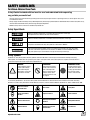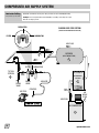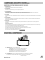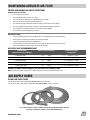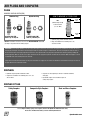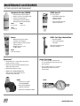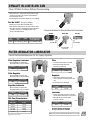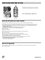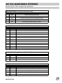
1
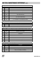
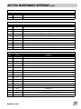
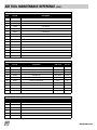
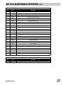
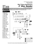
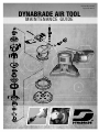
Reorder No. D15.04
Supersedes D07.18
DYNABRADE AIR TOOL
MAINTENANCE GUIDE
TABLE OF CONTENTS
SAFETY .............................................................................................................................................................................pg. 3
Guidelines/ Symbols ....................................................................................................................................................pg. 3
COMPRESSED AIR SUPPLY SYSTEM.............................................................................................................................pg. 4-6
Air System Diagram.................................................................................................................................................pg. 4-5
Selecting A Compressor ...........................................................................................................................................pg. 5-6
Defining CFM .............................................................................................................................................................pg. 6
MAINTAINING ADEQUATE AIR FLOW / AIR SUPPLY HOSES ..............................................................................................pg. 7
AIR PLUGS / COUPLERS ....................................................................................................................................................pg. 8
PREVENTATIVE MAINTENANCE .......................................................................................................................................pg. 9
MAINTENANCE ACCESSORIES .......................................................................................................................................pg. 10
Air Tool Lubricants / Dynaswivel® ...............................................................................................................................pg. 10
DynaJet In-Line Blow Guns/ Filter-Regulator-Lubricator.............................................................................................pg. 11
DROP-IN MOTORS / MOTOR TUNE-UP KITS....................................................................................................................pg. 12
AIR TOOL MAINTENANCE REFERENCE...........................................................................................................................pg. 13
Special Repair Tools.............................................................................................................................................pg. 13-15
General Repair Tools ............................................................................................................................................pg. 15-17
PERFORMANCE ASSURANCE ....................................................................................................................................pg. 18-19
MEASUREMENT CONVERSION TABLE
REFERENCE / CONTACT INFORMATION...........................................................................................................................pg. 20
CAREFULLY READ ALL INSTRUCTIONS BEFORE OPERATING,
MAINTAINING OR SERVICING ANY POWER TOOL
CONTACT YOUR DYNABRADE REPRESENTATIVE FOR PRICING OF PRODUCTS SHOWN IN THIS GUIDE
2
dynabrade.com
SAFETY GUIDELINES
For Various Abrasive Power Tools
Safety Booklet included with tool must be read and understood before operating
any portable pneumatic tool!
• This page must be read and understood by operating personnel and safety manager. Protection to operating personnel, as well as adjacent areas, shall
be maintained at all times.
• Always comply with: General Industry Safety & Health Regulations (www.osha.gov), EN Standards for Hand Held Non-Electric Power Tools (www.cen.eu),
American National Standards Institute (www.ansi.org) and Regional Regulations.
• Additional safety reference materials are available at Dynabrade.com.
Safety Signal Words
DANGER
Indicates a hazardous situation that, if not avoided, will result in death or serious injury.
This signal word is to be limited to the most extreme situations.
WARNING
Indicates a hazardous situation that, if not avoided, could result in death or serious injury.
Indicates a hazardous situation that, if not avoided, could result in minor or moderate injury.
It may also be used without the safety alert symbol as an alternative to “NOTICE.”
NOTICE
Is the preferred signal word to address practices not related to personal injury. The safety alert symbol
shall not be used with this signal word. As an alternative to “NOTICE”, the word “CAUTION” without the
safety alert symbol may be used to indicate a message not related to personal injury.
Safety Symbols
Dynabrade Inc. safety labels/symbols follow the guidelines outlined in ISO 3864. In order to help users understand the meaning of the safety
labels/symbols, the standard allows the reproducing of the figures and captions below. Some colored symbols are reproduced in this document in
grayscale. A complete color version may be found at Dynabrade.com.
WARNING
A black graphical symbol
inside a yellow triangle
with a black triangular
band defines a safety sign
that indicates a hazard.
PROHIBITION
A black graphical symbol
inside a red circular band
with a red diagonal bar
defines a safety sign that
indicates that an action
shall not be taken or shall
be stopped.
MANDATORY ACTION
A white graphical symbol
inside a blue circle defines
a safety sign that indicates
that an action shall be
taken to avoid a hazard.
For consistency Dynabrade Inc. also uses the above symbols and word definitions in collateral material, which includes this Pneumatic Tool Safety
Guidelines. For product safety information in Product Manuals, Instructions, and other Collateral Materials, Dynabrade Inc. adheres to ANSI Z535.6-2006.
Refer to Instruction
Manual/Booklet
Fire Hazard
Safety Alert
Eye Protection Must
Be Worn
Explosion Hazard
Air Hose Hazard
Electric Shock Hazard
Hearing Protection Must
Be Worn
Entanglement Hazard
Vibration Hazard
Respiratory Protection
Must Be Worn
Crush Hazard
dynabrade.com
3
COMPRESSED AIR SUPPLY SYSTEM
Lubricator Setting
1 Drop /Minute per 20 SCFM
Dynabrade recommends one drop of air lube per minute for each 20 SCFM (566 L/Min)
Example: If the tool specifications state 40 SCFM (1,133 L/Min), set the drip rate of your
lubricator at 2 drops per min.
REGULATOR
CLOSED LOOP PIPE SYSTEM
(SLOPED IN THE DIRECTION OF AIR FLOW)
FILTER
LUBRICATOR
AIR FLOW
RECEIVER
5
(AIR STORAGE TANK)
4
REGULATOR
FILTER
TO TOOL
STATION
6
LUBRICATOR
BALL
VALVE
DRAIN
VALVE
REFRIGERATED
AIR DRYER
DRAIN
VALVE
COUPLER
AIR TOOL
3
AIR HOSE
BALL
VALVE
AIR
INTAKE
FILTER
1
AIR FLOW
90 PSIG MAX (6.2 Bar)
AIR COMPRESSOR
2
4
dynabrade.com
COMPRESSED
AIR
SUPPLY
SYSTEM
COMPRESSED AIR
SUPPLY
SYSTEM
(CONT.) (CONT.)
COMPRESSED AIR SYSTEMS SHOULD INCLUDE THE FOLLOWING:
1. AIR INTAKE FILTER
Incoming air must be filtered to remove dust and other contaminants.
2. AIR COMPRESSOR
The filtered air is compressed using; a screw, or reciprocating compressor.
3. AIR COOLING/DRYING
Air usually contains a significant amount of water vapor. As air is compressed its temperature is dramatically raised, so cooling of the
compressed air is required. As the air is cooled, the water vapor condenses and water is removed.
4. AIR STORAGE
A tank called an air receiver is placed downstream from the air cooler/dryer. The air receiver reduces demand fluctuations in the compressed air
system.
5. AIR DISTRIBUTION
A system of pipes and regulators carry compressed air from the compressor to the work areas. This system includes various isolation valves,
fluid traps, and provides additional air storage.
6. POINT OF USE
At the work area, a feeder pipe with an isolation valve, filter, regulator and lubricator, carry compressed air to a hose that supplies the air
powered tool.
Filter-Regulator-Lubricator:
Proper air tool maintenance requires delivering the required pressure and volume of clean, lubricated, compressed air to the air motor. Proper
use of an air filter-regulator-lubricator will help to protect portable air tools.
The filter helps to prevent water and particulate contaminates from entering the air motor.
The regulator accurately controls air pressure to the tool to further protect moving parts of the air motor.
The lubricator can be set to provide an adequate amount of oil.
This formula can be used to approximate oil drip rate. – (Pressure/PSI X SCFM)
1000
SELECTING A COMPRESSOR
A)
COMPRESSOR TYPE – Base on your PSIG (Bar) needs
0 to 80 PSIG (5.5 Bar)– You may only need a single stage compressor
80 to 250 PSIG (17.2 Bar)– You will need a two-stage compressor
Two-stage compressors are recommended when tool usage is continuous.
Note: Dynabrade air tools require air pressure of 90 PSIG (6.2 Bar)
B)
AIR CONSUMPTION – Determine the total demand SCFM (L/Min). List the requirements for all equipment,
tools and other air consumption variables (both continuous and intermittent air usage demands).
continued on next page
dynabrade.com
5
SELECTING A COMPRESSOR (CONT.)
C)
COMPRESSOR HORSEPOWER (hp) – Use the determined total demand SCFM (L/Min) and add
approximately 20% for system variables. Add ______% for (your) future growth.
If the above total equals less than 100 SCFM(2,832 L/Min) divide this total by 4 to find the compressor hp.
If the total is over 100 SCFM(2,832 L/Min) divide by 5 to find the compressor hp.
Example: System requirements = 165 SCFM (4,673 L/Min) @ 100 PSIG (6.9 Bar)
165 ÷ 5 = 33 hp.
Suggested Compressor Size: ~30 to ~40 hp.
D)
AIR STORAGE TANK SIZE - As a general rule, the larger the tank (receiver) the better. Use a larger receiver for installations where larger air flows
of short duration are expected.
E)
CONTROLS
Stop-Start – The motor stops when the compressor unloads and starts again when the pressure in
the receiver drops. Use a stop-start pressure switch control for a small system. (Compressors up to 15 hp.)
Continuous Run – Equipped with constant pressure control, loading and unloading as the supply of
compressed air in the receiver drops or reaches a maximum.
DEFINING CFM
The term CFM is often confusing and difficult to define. One definition does not satisfy all conditions we encounter when dealing with applications
throughout the world.
It is important to understand that air is a compressible fluid. Conditions are dependent on location, time of year, altitude, etc.
Because of these atmospheric variations (air pressure, temperature, and air density) the fluid properties of air are constantly changing.
For example, conditions in Los Angels, CA, USA, a location at sea level with an atmospheric pressure around 14.69 PSIA., will vary significantly to
the conditions that exist in Denver, CO, USA, at an altitude of 5280 feet above sea level, and an atmospheric pressure of around 12.12 PSIA.
For this reason, Dynabrade Inc. adheres to measuring maximum air flow in standard cubic feet per minute (SCFM). NOTICE: ISO Standard: 68°F,
0% relative humidity, 14.5 PSIA (air pressure at sea level).
Standard Cubic Feet per Minute (SCFM) is typically used as a standard reference condition to measure air flow rate under atmospheric pressure at
sea level. This is different from measuring Actual Cubit Feet per Minute (ACFM). ACFM is typically used to rate the air compressor system’s
performance at an actual site’s existing air pressure, temperature and humidity.
6
dynabrade.com
MAINTAINING ADEQUATE AIR FLOW
PREVENT AND ELIMINATE AIR SUPPLY RESTRICTIONS
Common causes of restriction:
•
The air supply hose is too long.
•
The inside diameter (i.d.) of the hose is too small.
•
The air connections or fittings have an inside diameter that is too small.
•
There are too many air connections or fittings being used.
•
If an inline filter is being used, the unit may be too small or the filter element may be plugged.
•
If an inline regulator is being used, the unit may be to small, not adjusted properly or defective.
•
The air supply hose, air fitting, air tool inlet or air tool exhaust may be plugged.
•
If the air tool has a speed regulator it may be closed.
AIR SUPPLY HOSE
•
Use the air supply hose with the correct inside diameter as is recommended by the air tool manufacturer.
•
Use the shortest air supply hose possible for the task being performed.
•
Longer air supply hoses require larger inside diameters.
•
Coiled air supply hoses appear much shorter than they actually are. When using a coiled hose, make sure
that the inside diameter is large enough to compensate for the length.
AIR SUPPLY HOSE RECOMMENDED CHART
Air Motor SCFM
(Standard Cubic Feet per Minute)
Hose & Fitting I.D. Required
Recommended Length
Air Supply Hose
22 SCFM (623 L/Min)
1/4"
(6 mm)
1' - 8'
(0.3048 m – 2.44 m)
28 SCFM (793 L/Min)
3/8"
(10 mm)
1' - 25'
(0.3048 m – 8.7 m)
35 SCFM (991 L/Min)
3/8"
(10 mm)
1' - 20'
(0.3048 m – 6.10 m)
45 SCFM (1,274 L/Min)
3/8"
(10 mm)
1' - 10'
(0.3048 m – 3.042 m)
73 SCFM (2,067 L/Min)
1/2"
(15 mm)
1' - 20'
(0.3048 m – 6.10 m)
CHOOSE THE CORRECT INSIDE DIAMETER(I.D.) AND LENGTH OF AIR SUPPLY HOSE
NOTE: To increase the length of air supply hose it will be necessary to increase the inside diameter of the hose.
AIR SUPPLY HOSES
FLEXIBLE AIR SUPPLY HOSES
3/8" I.D. with two male 1/4" NPT fittings. PART NUMBER 11292 - 8 feet (2.44 m) long
1/2" I.D. with one male and one female 1/2" NPT fitting. PART NUMBER 95870 - 5 feet (1.53 m) long
For a complete offering of air line assemblies, reference the Dynabrade Industrial Power Tools,
Accessories and Abrasives Catalog or check online: Dynabrade.com
dynabrade.com
7
AIR PLUGS AND COUPLERS
PLUGS
COMPARE AIRFLOW SCFM(LPM)
Common Plug
HOW TO MEASURE A TYPICAL PLUG
Dynabrade Plug
Inside
Dia.
NPT
(National Pipe Thread)
is the thread size.
(i.e. 1/4" NPT)
30 SCFM (850 LPM)
.2010 in. (5.11 mm) I.D.
Thread
Size
74 SCFM (2,096 LPM)
.3070 in. (7.80 mm) I.D.
• Dynbrade plugs provide maximum air flow
NOTE: All information is based on the size of the INSIDE DIAMETER @ 90 PSIG
(6.2 Bar) in conjunction with the mating coupler.
• Plugs are available in the following sizes: 1/4",
3/8"and 1/2" NPT.
IMPORTANT: It is not always advisable to use an air plug and coupler to connect an air tool to the air supply hose. Contaminants can enter the air tool
through plug and coupler connections. This often happens when an operator changes to a different tool. The hose and coupler may fall to the floor, or
disconnected air tools are left lying exposed in the work area. The exposed ends of the plug and coupler will collect abrasive, grinding, sanding and
polishing particles. When the air tool is once again connected to the air supply, these particles are blown into the air motor. When this happens it causes
considerable wear to the internal parts of the air motor.
Using a direct thread connection between the air power tool and the air supply hose can reduce the likelihood of contamination entering an air motor at
the point where the air connection is made.
COUPLERS
• Dynbrade couplers provide maximum air flow
• Couplers are available in the following sizes: 1/4", 3/8"
and 1/2" NPT.
• Couplers are sold separately as well as in matched assemblies
with plugs.
• Dynabrade couplers come in different styles to
satisfy every request.
COUPLER STYLES
Safety Couplers
Composite-Style Couplers
Steel and Brass Couplers
For a complete offering of plugs and couplers, reference the Dynabrade Industrial Power Tools,
Accessories and Abrasives Catalog or check online: Dynabrade.com
8
dynabrade.com
PREVENTATIVE MAINTENANCE
PROVIDE A GOOD AIR SUPPLY:
1. REDUCE OR ELIMINATE CONDENSATION (WATER VAPOR) FROM THE AIR SUPPLY
• Water traps and drains
• After-coolers
• Refrigerated air dryer
2. PREVENT DEBRIS FROM ENTERING THE AIR MOTOR
• Filter the air.
• Keep the air inlet connections, plugs and couplers clean, free of dust and debris.
• Keep exhaust mufflers and elements in place. Muffler elements provide a barrier that will prevent dust
from being pulled into the air motor.
• Do not use compressed air to blow-off the tool, this could force debris into bearings.
3. LUBRICATE THE AIR MOTOR
• Use an automatic lubricator to supply the correct weight and amount of air motor oil.
• Supply the air motor oil manually, directly into the air inlet. Apply 2-3 drops throughout the day.
i.e.,
start-up
mid-morning
lunch
mid-afternoon
end of the day
ELIMINATE ANY BLOCKAGE OF AIRFLOW, IN OR OUT:
1. KEEP THE TOOL’S AIR INLET CLEAR OF ANY DEBRIS
2. CLEAN OR REPLACE EXHAUST MUFFLER ELEMENTS AS NEEDED
LUBRICATE GEARS, SLEEVES, BEARINGS AND SLIDERS
1. USE THE MANUFACTURER’S SPECIFIED LUBRICANT
• Apply the suggested amount at the recommended interval.
Note: This is usually found in technical support literature, i.e., tool manuals, parts pages, etc.
USE THE TOOL, ACCESSORY OR RELATED PRODUCT AS SPECIFIED BY DYNABRADE, INC.
1. ADHERE TO THE SPECIFIED MAXIMUM OPERATING AIR PRESSURE
2. ADHERE TO THE SPECIFIED MAXIMUM OPERATING RPM FOR ALL TOOLS AND ACCESSORIES
i.e.,
grinding wheels
mounted points
cut-off wheels
sanding discs
burrs
back-up pads, etc.
dynabrade.com
9
MAINTENANCE ACCESSORIES
Air Tool Lubricants and Dynaswivel
®
Dynabrade Air Lube (10W/NR)
95848 Gear Oil
2.5 oz. (74 ml) tube
• Formulated for pneumatic equipment.
• Absorbs up to 10% of its weight in water.
• Prevents rust and formation of
gum/sludge for longer tool operation
with greater power and less downtime.
95821
4 oz. (118 ml)
• Formulated for geared tools
utilizing a wick-type
lubrication system.
• Failure to lubricate will cause
premature gear failure.
95843
1 gal. (3.8 l)
95842
1 pt. (473 ml)
Grease
95541 Push-Type Lubricant Gun
• One-hand operation
• Can be used with Grease
or Gear Oil
• Multi-purpose grease for all types
of bearings, cams and gears.
• High film strength; excellent resistance
to water, steam, etc.
• Workable range: 0°F (-17˚C)
to 300°F (148˚C).
Note: Have a dedicated gun for
each type of lubricant.
95542
10 oz. (283.5 g) tube
Airline Test Gauge
Dynaswivel®
®
• The Dynaswivel is a “universal-joint” that connects
portable air tools to an air line.
• It improves tool maneuverability, minimizes operator
fatigue and extends hose life.
• Patented; works great on air tools.
•
Use to test air pressure at selected areas
of an air supply system. Test at the tool, to see
specific pressure.
• Comes complete with brass "T" connector,
quick disconnect coupler and a round
pressure gauge.
• SWIVELS 360° AT TWO LOCATIONS which
allows air hose to drop straight to the floor,
no matter how the tool is held.
94300
94315
• Air flow: up to 33 SCFM
(935 LPM) MAXIMUM.
• Non-marring, lightweight,
composite construction.
• Many other configurations available.
10
dynabrade.com
DYNAJET IN-LINE BLOW GUN
Clean Off Work Surfaces Without Disconnecting
• Only connect once... permanently mounts between coupler
and air hose to purge air line of water and contaminants
before starting up air tools.
• Durable aluminum construction, weighs only 2 oz. (0.06 kg).
94467
Part No. 94467 Safety Tip Design
• Reduces line pressure down to 30 PSIG (2 Bar).
• Meets O.S.H.A. requirements of special relief hole in nozzle,
which limits pressure to 30 PSIG (2 Bar) when dead-ended
and used on an air line of 150 PSIG (10.3 Bar) or less.
• 10.3 Bar (150 PSIG) maximum
Proper Installation for DynaJet Blow Gun Connection
Part
Number
Thread
Size
Weight
Recommended Air Flow
Range SCFM (L/Min)
94467
1/4" Female NPT
0.06 kg
up to 35 SCFM (991 L/Min)
Air Line
Blow Gun
Coupler
1/4" Male NPT
1/4" Male NPT
1/4" Female NPT
on both ends
FILTER-REGULATOR-LUBRICATOR
Cost-Effective Maintenance for Air Supply Systems
Filter
Filter-Regulator-Lubricator
• Five-micron filter element is standard.
• Unit has modular connections with
mounting brackets for easy installation.
Part Number
Air Inlet Thread
10681
1/2" NPT
• Manual push-button drain easily
discharges contaminants.
10681
Part Number
Air Inlet Thread
10671
1/2" NPT
10671
Filter-Regulator
Regulator
• Unit has modular connections with
mounting brackets for easy installation.
Part Number
Air Inlet Thread
10677
1/2" NPT
Regulator-Lubricator
• Compensation built into unit responds
faster to changes in incoming pressure and
flow.
• Built-in PSI pressure dial guage.
10677
• Unit has modular connections with
mounting brackets for easy installation.
Part Number
Air Inlet Thread
10679
1/2" NPT
Pressure Drop Across FRL
PSI (Bar)
15 (425)
2.0 (.14)
30 (850)
3.0 (.21)
45 (1,274)
6.0 (.41)
60 (1,699)
7.0 (.48)
75 (2,124)
8.0 (.55)
dynabrade.com
Air Inlet Thread
10673
1/2" NPT
Lubricator
• Built-in check valve permits tool to be filled
with oil without having to turn off air pressure.
FRL Flow Characteristics
Air Flow
SCFM (L/Min)
Part Number
10673
10679
• Adjustable oil drop to meter amount
of oil into air system.
Part Number
Air Inlet Thread
10675
1/2" NPT
10675
Each unit includes two bushings
for easy conversion to 3/8" NPT.
Additional Specifications: Maximum Operating Pressure 145 PSIG.
11
DROP-IN MOTORS/TUNE-UP KITS
• Drop-In Motors are complete replacement air motor assemblies.
• Tune-Up Kits contain assorted and high wear replacement parts.
To view a complete offering, go to Dynabrade.com
Tune-Up Kit
Drop-In Motor
GUIDELINES FOR INSTALLING A DROP-IN MOTOR
Installing a Drop-In Motor is relatively simple to perform. However, there are some necessary steps to follow to be successful.
1) Before attempting the installation of a drop-in-motor, review and understand the specific power tool “Disassembly and Assembly Instructions”.
Note: Though a technician is not disassembling every component, it is important to use correct techniques when removing and
installing an air motor assembly.
Before proceeding, have the necessary Special Repair Tools to remove or install the motor.
Note: View last page of tool manual for a list of available Special Repair Tools.
2) Remove used air motor.
3) Remove old muffler elements.
4) Clean the motor housing, air inlet and exhaust passages before installing the new air motor assembly.
5) Install new muffler elements.
6) Correctly line-up air motor assembly with the inside of motor housing. Install motor.
7) Follow all primer/adhesive, and torque specifications for fastening the motor assembly into the housing.
Note: Allow 30 minutes for adhesives to cure before running motor.
8) With new motor properly fasten in housing, place three drops of 10Wt. non-detergent air motor oil into air inlet.
Connect to air supply and test motor. Use a tachometer to check work spindle RPM.
Important: Verify correct maximum free speed.
• Drop-in Air Motor Installation Completed
TUNE-UP KIT SUGGESTION
Search the Dynabrade website under Repair Tutorials, or use the model number of the tool. Refer to the last page of the tool manual/parts
page for Tune-Up Kit information.
12
dynabrade.com
AIR TOOL MAINTENANCE REFERENCE
Special Repair Tools Designed by Dynabrade
Repair Collars & Fixtures Used to protect tool during servicing.
Item
Part No.
Description
1
96399
.4 hp Motor / Valve Housing (2012 Design)
2
96402
.4 hp Motor / Valve Housing (2009 to 2012 Design)
3
96461
.4 hp Motor / Valve Housing, 7˚ Motor Housing, Right Angle Housing
4
51989
1 hp Motor / Valve Housing, 1.3 hp Valve Housing
5
57092
Palm & Two-Hand, Dynorbital / Gear-Driven / Dynalocke
Lock Ring/ Nut Wrenches For removal & installation of motors, spindles & plugs.
Item
Part No.
Description
6
50971
.4, .5, .7, & 1 hp Motors as specified
7
56058
Palm & Two-Hand, Dynorbital® / DynaLocke®
8
56599
(formerly 96337) 5", 6" & 8" Two-Hand Gear-Driven / Use with composite housing.
9
94598
100 K Pencil Grinder
10
94605
35, 50, 60 K Pencil Grinder
11
94607
QCK-Change Pencil Grinder
12
95900
.5 & .7 hp Steel Housing Die Grinders (Regulator Plug)
13
96165
Mini-Angle Head
14
96393
.4 hp Motor / Valve Housing (2012 Design)
15
96460
.4 hp Valve / Motor Housing (34 mm Lock Nut)
16
96479
Retainer Wrench / Pencil Grinder (Use for all Models except, Wrenchless Collet.)
17
97782
1 hp Right Angle, Mini-Angle Head, 1.3 hp Right Angle
Gear/ Plate/ Carrier/ Housing; Disassembly & Assembly Tools
Item
Part No.
Description
18
96181
Pinion Wrench 8" (203 mm) Two-Hand Gear-Driven Sander
19
96182
Front Plate Tool 8" (203 mm) Two-Hand Gear-Driven Sander
20
53698
Carrier Tool 1 hp (2-Flats)
Bearing Removal Tools Used to remove bearings
Item
Part No.
Description
21
96210
02650, 02696 Bearings (5 mm Bearing I.D.)
22
96211
01015, 02648 Bearings (6 mm Bearing I.D.)
23
96212
11016 Bearing (6.35 mm Bearing I.D.)
24
96213
02649 Bearing (8 mm Bearing I.D.)
25
96214
01007 Bearing (10 mm Bearing I.D.)
dynabrade.com
13
AIR TOOL MAINTENANCE REFERENCE (CONT.)
Bearing Press Tools Used to install bearings.
Item
Part No.
Description
26
96216
02650, Bearing
27
96239
02651, 56052, 11831, 54520 Bearings
28
96240
02649, 12153 Bearings
29
96241
01015, 12152 Bearings
30
96242
02696, 12151, 12058, 12078 Bearings
31
96243
11016, 02648, 02057 Bearings
32
96244
01007, 01206 Bearings
33
96418
51651, 51686 Pencil Grinder Bearings
34
96419
51544, 51685 Pencil Grinder Bearings, 51078 Bearing
35
57091
5", 6", 8" All Dynorbital® and Two-Hand Gear-Driven Sanders
Bearing and Gear Pullers Used to remove bearings and gears.
Item
Part No.
Description
36
56056
Bearing Puller / 56052 Bearing
37
57099
Bearing Puller / 56052 Bearing; Use if the bearing remains in the motor shaft balancer.
Collars & Fixtures Used for holding motor and gear assemblies during disassembly or assembly.
Item
Part No.
Description
38
96245
Machined Size .992 I.D. / Dynadie
39
96246
Machined Size 1.028 I.D. / .4 hp (Mini-Dynafile® II )
40
96247
Mini-Angle Head
41
96248
Machined Size 1.390 I.D. / Ring Gear .7 hp Dynastraight®
42
96208
Machined Size 1.50 I.D. / 1.3 hp Motor
43
96249
Machined Size 1.980 I.D. / Dynorbital® Supreme Sander
44
96250
Machined Size 2.290 I.D. / 2.0 hp Right-Angle Tools
45
96209
Motor Clamp; 1 hp
46
96231
Tool Plate / Use with 96232 Arbor Press.
Assorted Special Pencil Grinder Repair Tools
Item
Part No.
Description
47
51694
Shaft Lock Pin (All Pencil Grinders except Quick- Change)
48
94999
Air Bushing Removal Tool (35, 50, 60 K & Quick-Change Pencil Grinders)
49
96408
Motor Top Plate Wrench (All Pencil Grinders except Quick- Change)
50
96483
Bullet (Use for installing Grip on Pencil Grinders)
51
96486
Collet Insert Removal Tool (All Pencil Grinders except Quick- Change)
14
dynabrade.com
AIR TOOL MAINTENANCE REFERENCE (CONT.)
Arbor Press Used for disassembly/ assembly
Item
Part No.
Description
52
96232
Arbor Press (# 2)
53
96230
Press Ram (General purpose non-marring brass ram)
Special Repair Tool Kits
Item
Part No.
Description
54
11270
Original Dynafile® with screw-in motor / Use to replace contact and idler wheel components.
55
11288
Dynafile® with cam-lock motor / Use to replace contact and idler wheel components.
56
57098
Dynorbital® Supreme and Spirit Sander Repair Kit / Use for Supreme and Spirit models.
57
57260
5", 6" Two-Hand Dynorbital® and DynaLocke® / Use with composite housing models.
58
57325
8" Two-Hand Dynorbital® / Use for composite and aluminum housing models.
59
57525
Mini-Dynorbital® / Use for composite housing models. (Mdl's 57500, 57501, 57502, 57503)
60
96283
5", 6", 8" Two-Hand Gear-Driven / Use for composite housing models.
61
96405
Finesse-it, Two-Step Tools / Use for Mdl's 57240(45), 57125, 57126, 57500, 57502 & Supreme/Spirit
62
56077
Lightweight Palm-Style Dynorbital® / Use for aluminum housing models.
63
56577
Mini-Lightweight Palm-Style Dynorbital® / Use for aluminum housing models.
General Repair Tools Wrenches: Open End
Item
Part No.
Description
64
96314
4 mm Open End / Dynadie III
65
95731
8 mm Open End / Pencil Grinder
66
96076
12 mm Open End
67
95262
14 mm Open End
68
96453
16 mm Open End
69
95263
17 mm Open End
70
95281
19 mm Open End
71
95823
21 mm Open End
72
95304
24 mm Open End
73
50679
26 mm Open End
74
59293
26 mm Offset Open End / 3" HiVac Dynorbital Spirit
75
95987
5/16" Open End
76
96031
7/16" Open End
77
96032
11/16" Open End
78
95176
3/4" Open End
79
98277
1-3/8" Open End
80
11278
1-1/2" Open End / Original Dynafile with screw-in motor
81
98283
1-5/8" Open End
dynabrade.com
15
AIR TOOL MAINTENANCE REFERENCE (CONT.)
Hex Key Wrenches
Item
Part No.
Description
82
95251
1.5 mm Hex Key
83
96401
2 mm Hex Key
84
95252
2.5 mm Hex Key
85
95266
3 mm Hex Key
86
95331
4 mm Hex Key
87
96034
12 mm Hex Key
88
96215
15 mm Hex Key
89
95050
5/64" Hex Key
90
95052
3/32" Hex Key
91
95048
1/8" Hex Key
92
95049
3/16" Hex Key
93
95134
9/64" Hex Key
94
95303
1/4" Hex Key
95
95521
5/16" Hex Key
96
95051
3/8" Hex Key
Pin Style Spanner Wrenches
Item
Part No.
Description
Cntr/ Cntr
Pin Dia.
97
96347
Adjustable-Face
10 to 100 mm
2.9 mm
98
96148
Fixed-Face / Mdl.# 50370
24 mm
3 mm
99
94925
Fixed-Face / Mdl.# 50302, 50306, 52620, 52625
32 mm
4 mm
100
96348
Adjustable-Face
10 to 100 mm
5.8 mm
101
96507
Fixed-Face / Mdl.# 52515
1-1/16"
1/8"
102
95267
Fixed-Face / Mdl.# 50343
5/8"
1/8"
103
95270
Fixed-Face / Mdl.# 52700
1"
1/8" Square
104
96318
Adjustable-Face / Mdl.# 50273
5/8" to 2"
5/32"
105
96038
Fixed-Face
1-9/32"
1/4"
106
97787
Pin/Hook Style (Adjustable)
3/4" to 2"
1/8"
Generic Hand Tools
Item
Part No.
Description
107
96341
Inch Folding Hex Key Set (5/64" to 1/4")
108
96342
Metric Folding Hex Key Set (1.5 mm to 8 mm)
109
96343
Internal / External Retaining Ring Pliers
110
96344
3/32" Dia. Pilot Punch (Use to remove roll pins.)
111
96345
15/16" Bearing Separator
112
96346
2" Bearing Separator
16
dynabrade.com
AIR TOOL MAINTENANCE REFERENCE (CONT.)
Generic Hand Tools (cont.)
Item
Part No.
Description
113
96349
Small Torque Wrench (30-150 in. lbs.)
114
96350
Large Torque Wrench (100-1000 in. lbs.)
115
96351
Bench Vise (4" Jaw)
116
96352
4" (102 mm) Soft Jaw Caps (Bronze)
117
96353
(8 piece) Drive Pin Punch Set; 1/16", 3/32", 1/8", 5/32", 3/16", 7/32", 1/4", 5/16"
118
96354
Feeler Gauges (.0015 to .025)
119
96355
Small Phillips Screwdriver
120
96356
Large Phillips Screwdriver
121
96357
Groove Pliers (Channel Lock Style)
122
96358
Standard Pliers (slip-joint style)
123
96359
Needle Nose Pliers
124
96360
10" Adjustable Wrench (Crescent Style)
125
96338
11" Wide-Opening Adjustable Wrench; 3" (76 mm) jaw opening
126
96361
3/8" Drive, Ratchet (includes metric and English socket set)
127
96362
3/8" Drive, Breaker Bar; 10" (254 mm) long flex handle
128
96363
Small Slotted Screwdriver
129
96364
Large Slotted Screwdriver
130
96365
3/8" to 1/4" Drive, Socket Adapter
131
96366
12 oz. Soft Hammer
132
96367
8 oz. Ball Peen Hammer
133
96368
Electronic Tachometer
134
96373
11/16" Deep Socket
135
94315
Air Pressure Test Gauge / Use to check air supply pressure
136
80025
Load Cell / Used to measure the performance of various finishing air tools under load
137
80030
Test Tool Kit / Includes: 80025, 94315, 95842, and 96368
Parts Pages, Forms, Adhesive
Item
Part No.
Description
138
96369
Liquid Thread Locker (50 ml bottle)
dynabrade.com
17
PERFORMANCE ASSURANCE
Air Tool And Air System Inspection/Diagnosis
AIR TOOL INSPECTION
Inspect the air tool.
Has the motor been oiled?
This silencer shows evidence of oil.
Is the tool’s air inlet clean?
This air motor received “Last-Rites Oil.”
Notice, the puddle of oil appears clean.
Can the tool’s spindle be turned by hand?
Is the tool’s exhaust (muffler/silencer) clean?
“The spindle won’t turn.”
This usually indicates broken vanes.
Generally, broken vanes indicate that the
motor has not been oiled regularly.
AIR SYSTEM CHECK
Tachometer
❑ Affix a 1/2" (12 mm) square piece of reflective tape to the
tool’s spindle or pad.
❑
Aim the Laser Pointer at the reflective tape and run the tool.
(Operational distance: 2"/50 mm to 20"/500 mm)
❑
Read RPM. (Notice: Refer to User’s Manual for more detailed
instructions.)
PSI Gauge
❑ Connect Air Gauge and air supply hose to the air inlet of the tool.
❑ Run the tool and adjust air supply pressure to 90 PSIG (6.2 Bar).
Condition of Air Hose (Continued)
❑ How many coupler connections exist from the drop to
the workbench?
❑
❑
Are there any “T’s” or a manifold at the workbench?
How can Dynaswivel® prolong the life of the hose?
Filter-Regulator-Lubricator
❑ FRL – is it present? If yes, is it working?
❑ Filled with oil? Set for proper lubrication?
❑ What type of oil? (Weight, Non-detergent vs. Detergent – Notice:
Non-detergent oils contain little to no solvents. Air Tool Oils with
“conditioner” usually contain solvents. Example: Both Marvel®
Air Tool Oil and Marvel® Mystery Oil contain mineral spirits,
a common solvent used as paint thinner.)
Condition of Coupler and Plug
❑ Check for wear or damage to coupler and/or plug.
❑ Can the I.D. of the plug supply enough air to the tool?
❑
Condition of Air Hose
❑ Check to see if the hose is frayed or cracked?
Are there reducer bushings being used to connect the air supply
to the FRL?
❑
What size is the fitting connecting the FRL to the air line that is
supplying the air to the workbench?
(see “Cost of an Air Hose Leak” on reverse side)
❑
❑
❑
18
What is the length of the hose?
Match length and I.D. of hose to air requirement of tool.
Is there a hose reel?
❑
❑
Are there any “T’s” or manifolds coming directly off the FRL?
What material is the pipe that is carrying the air supply?
Black Iron?
dynabrade.com
PERFORMANCE ASSURANCE
(CONT.)
Air Supply Hose Recommendations
Air Motor SCFM
22
28
35
45
73
Hose and Fitting I.D.
Recommended Length
1/4"
3/8"
3/8"
3/8"
1/2"
1' - 8'
1' - 25'
1' - 20'
1' - 10'
1' - 20'
(623 L/Min)
(793 L/Min)
(991 L/Min)
(1274 L/Min)
(2067 L/Min)
RANDOM ORBITAL SANDER SWIRL-FREE CHECKLIST
Equipment Check:
Sanding Techniques (Continued)
❑
Random Orbital Sander
❑
90 PSIG (6.2 Bar) is the required operating air supply
pressure. Check the air pressure at the sander while it is
running. Note: Promote the use of Dynabrade maximum flow
plugs and couplers to ensure proper airflow.
❑
Confirm that the tool is running at the rated “Free Speed” RPM.
On an average a 10,000 RPM non-vacuum sander will run at 9,500
RPM; a 12,000 RPM non-vacuum sander will run at 11,500 RPM.
A vacuum sander normally runs slightly slower.
❑
Inspect the balancer bearing (pad bearing). Remove the back-up
pad and rotate the balancer bearing shaft while holding the
counterbalance stationary. The balancer shaft should turn freely.
Follow a set pattern when sanding. It is suggested to pass
over the surface following a “North, South, East, West” pattern
(see below), overlapping each pass 1/4 the diameter of the
back-up pad and abrasive.
This insures that the
previous scratches
End
are removed and
that a uniform
finish is achieved.
Two “patterns”
per sanding
step are
recommended.
Back-Up Pad
❑
Start
Inspect the face of the sanding pad. The pad must be flat and smooth,
without any defects. Check if they are using a Dynabrade back-up pad
that is “weight-mated” to the sander. Using another pad can make the
sander vibrate excessively and lead to an unacceptable finish.
❑
Frequently inspect abrasive for tears, folds, or build-up.
When changing abrasive to proceed to the next sanding step,
first inspect the condition of the abrasive that is on the sander.
If any defects are noticed in that abrasive, remove it and install
another piece of the same grain and sand the work surface
again before proceeding on to the next sanding step.
❑
Always clear away sanding dust and abrasive debris
before progressing to the next sanding step with a finer
“grit” abrasive.
Sanding Techniques:
❑
Always START the sander ON the surface, and STOP the sander
OFF the surface.
❑
When sanding keep the sander, and pad FLAT on the surface.
Important: Do not exert heavy downward force on the sander. Apply
enough downward force to keep the back-up pad and abrasive flat on
the surface allowing the back-up pad to orbit freely over the surface.
THE COST OF AN AIR HOSE LEAK
The cost of one leaking air hose:
One 1/16" hole in a hose leaks at 100 PSIG:
➤ 4.25 cubic feet per minute (CFM)
240
➤ 255 cubic feet per hour
x
working days
per year
➤ 2,040 cubic feet in an 8-hour day
1,468,800 x
➤ 6,120 cubic feet per 24 hours
*Costs will vary based on local charges per kilowatt-hour.
air lost in cf
per year
6,120
= 1,468,800
leakage in cf
per 24 hours
$.00041*
air lost in cf
per year
= $602.21*
cost per cf based on typical
energy costs per kilowatt-hour
total cost
per year!
PLUG CONNECTORS
Compare Airflow
SCFM (L/Min)
All information based upon size
of I.D. at 90 PSIG (6.2 Bar) in
conjunction with mating coupler.
dynabrade.com
Common Plug Connector
➤ 25 SCFM (708 L/Min)
Dynabrade Plug Connector
➤ 76 SCFM (2152 L/Min)
19
MEASUREMENT CONVERSION (US TO INTERNATIONAL)
Type
Distance
Mass
Pressure
Speed
Flow
Power
U.S. Unit of Measure
Conversion Formula
Inch
Pound
PSIG
SFPM
SCFM
hp
x 25.4
x .454
÷ 14.5 (.0689) Alternative
x .3048
x 28.32
x 745.7
International
Unit of Measure
Millimeter (mm)
Kilogram (kg)
Bar
Surface Meters Per Minute (SMPM)
Liters Per Minute (L/Min)
Watts (W)
REFERENCE CONTACT INFORMATION
American National Standards Institute – ANSI
Government Printing Office – GPO
25 West 43rd Street
Forth Floor
New York, NY 10036
Tel: 1 (212) 642-4900
Email: www.ansi.org
Code of Federal Regulations (CFR)
Tel: 1-866-512-1800
Email: www.OSHA.com
Compressed Air & Gas Institute – CAGI
Sullair Corporation
(Air Compressor Technology)
1300 Sumner Ave.
Cleveland, Ohio 44115
Tel: 1-216-241-7333
Email: www.cagi.org
European Committee for
Standardization – CEN
CEN-CENELEC Management Centre
Avenue Marnix 17
4th Floor
B-1000 Brussels
Tel: + 32 2 550 08 11
Email: www.cen.eu
3700 E. Michigan Blvd.
Michigan City, Indiana 46360
Email: www.sullair.com
DYNABRADE CONTACT INFORMATION
DYNABRADE, INC.
DYNABRADE EUROPE S.àr.l.
8989 Sheridan Drive
Clarence, New York 14031-1490
Zone Artisanale
L-5485 Wormeldange–Haut
Luxembourg
DYNABRADE INDIA
ABRASIVE POWER TOOLS Pvt Ltd.
EL-54, TTC Industrial Area, M.I.D.C. Mahape, Electronic Zone
Navi Mumbai - 400705, Maharashtra, India
Website: Dynabrade.com
Automotive Website: Dynabradeauto.com
US Customer Service Email: [email protected]
European Customer Service Email: [email protected]
Automotive Customer Service Email: [email protected]
Call: US Toll Free: 1-800-828-7333
Canada Toll Free: 1-800-344-1488
India: +91 22 2763 2226
US & Int: (716) 631-0100
Eur.: +352 768 494 1
Fax: US: (716) 631-2073
Int.: (716) 631-2524
India: +91 22 2763 2228
Eur.: +352 768 495
®
DYNABRADE
© DYNABRADE, INC., 2015
PRINTED IN USA
D15._05/15